EP3034122B1 - Adaptateur en ligne pour un dispositif de thérapie respiratoire - Google Patents
Adaptateur en ligne pour un dispositif de thérapie respiratoire Download PDFInfo
- Publication number
- EP3034122B1 EP3034122B1 EP15200001.4A EP15200001A EP3034122B1 EP 3034122 B1 EP3034122 B1 EP 3034122B1 EP 15200001 A EP15200001 A EP 15200001A EP 3034122 B1 EP3034122 B1 EP 3034122B1
- Authority
- EP
- European Patent Office
- Prior art keywords
- assembly
- generating device
- adapter
- structured
- pressure generating
- Prior art date
- Legal status (The legal status is an assumption and is not a legal conclusion. Google has not performed a legal analysis and makes no representation as to the accuracy of the status listed.)
- Active
Links
Images


Classifications
-
- A—HUMAN NECESSITIES
- A61—MEDICAL OR VETERINARY SCIENCE; HYGIENE
- A61M—DEVICES FOR INTRODUCING MEDIA INTO, OR ONTO, THE BODY; DEVICES FOR TRANSDUCING BODY MEDIA OR FOR TAKING MEDIA FROM THE BODY; DEVICES FOR PRODUCING OR ENDING SLEEP OR STUPOR
- A61M16/00—Devices for influencing the respiratory system of patients by gas treatment, e.g. ventilators; Tracheal tubes
- A61M16/0057—Pumps therefor
-
- A—HUMAN NECESSITIES
- A61—MEDICAL OR VETERINARY SCIENCE; HYGIENE
- A61M—DEVICES FOR INTRODUCING MEDIA INTO, OR ONTO, THE BODY; DEVICES FOR TRANSDUCING BODY MEDIA OR FOR TAKING MEDIA FROM THE BODY; DEVICES FOR PRODUCING OR ENDING SLEEP OR STUPOR
- A61M16/00—Devices for influencing the respiratory system of patients by gas treatment, e.g. ventilators; Tracheal tubes
- A61M16/08—Bellows; Connecting tubes ; Water traps; Patient circuits
- A61M16/0816—Joints or connectors
-
- A—HUMAN NECESSITIES
- A61—MEDICAL OR VETERINARY SCIENCE; HYGIENE
- A61M—DEVICES FOR INTRODUCING MEDIA INTO, OR ONTO, THE BODY; DEVICES FOR TRANSDUCING BODY MEDIA OR FOR TAKING MEDIA FROM THE BODY; DEVICES FOR PRODUCING OR ENDING SLEEP OR STUPOR
- A61M15/00—Inhalators
- A61M15/08—Inhaling devices inserted into the nose
-
- A—HUMAN NECESSITIES
- A61—MEDICAL OR VETERINARY SCIENCE; HYGIENE
- A61M—DEVICES FOR INTRODUCING MEDIA INTO, OR ONTO, THE BODY; DEVICES FOR TRANSDUCING BODY MEDIA OR FOR TAKING MEDIA FROM THE BODY; DEVICES FOR PRODUCING OR ENDING SLEEP OR STUPOR
- A61M16/00—Devices for influencing the respiratory system of patients by gas treatment, e.g. ventilators; Tracheal tubes
- A61M16/06—Respiratory or anaesthetic masks
- A61M16/0666—Nasal cannulas or tubing
-
- A—HUMAN NECESSITIES
- A61—MEDICAL OR VETERINARY SCIENCE; HYGIENE
- A61M—DEVICES FOR INTRODUCING MEDIA INTO, OR ONTO, THE BODY; DEVICES FOR TRANSDUCING BODY MEDIA OR FOR TAKING MEDIA FROM THE BODY; DEVICES FOR PRODUCING OR ENDING SLEEP OR STUPOR
- A61M16/00—Devices for influencing the respiratory system of patients by gas treatment, e.g. ventilators; Tracheal tubes
- A61M16/08—Bellows; Connecting tubes ; Water traps; Patient circuits
- A61M16/0816—Joints or connectors
- A61M16/0833—T- or Y-type connectors, e.g. Y-piece
-
- A—HUMAN NECESSITIES
- A61—MEDICAL OR VETERINARY SCIENCE; HYGIENE
- A61M—DEVICES FOR INTRODUCING MEDIA INTO, OR ONTO, THE BODY; DEVICES FOR TRANSDUCING BODY MEDIA OR FOR TAKING MEDIA FROM THE BODY; DEVICES FOR PRODUCING OR ENDING SLEEP OR STUPOR
- A61M16/00—Devices for influencing the respiratory system of patients by gas treatment, e.g. ventilators; Tracheal tubes
- A61M16/08—Bellows; Connecting tubes ; Water traps; Patient circuits
- A61M16/0875—Connecting tubes
-
- A—HUMAN NECESSITIES
- A61—MEDICAL OR VETERINARY SCIENCE; HYGIENE
- A61M—DEVICES FOR INTRODUCING MEDIA INTO, OR ONTO, THE BODY; DEVICES FOR TRANSDUCING BODY MEDIA OR FOR TAKING MEDIA FROM THE BODY; DEVICES FOR PRODUCING OR ENDING SLEEP OR STUPOR
- A61M16/00—Devices for influencing the respiratory system of patients by gas treatment, e.g. ventilators; Tracheal tubes
- A61M16/10—Preparation of respiratory gases or vapours
- A61M16/1075—Preparation of respiratory gases or vapours by influencing the temperature
- A61M16/1095—Preparation of respiratory gases or vapours by influencing the temperature in the connecting tubes
-
- A—HUMAN NECESSITIES
- A61—MEDICAL OR VETERINARY SCIENCE; HYGIENE
- A61M—DEVICES FOR INTRODUCING MEDIA INTO, OR ONTO, THE BODY; DEVICES FOR TRANSDUCING BODY MEDIA OR FOR TAKING MEDIA FROM THE BODY; DEVICES FOR PRODUCING OR ENDING SLEEP OR STUPOR
- A61M16/00—Devices for influencing the respiratory system of patients by gas treatment, e.g. ventilators; Tracheal tubes
- A61M16/0057—Pumps therefor
- A61M16/0066—Blowers or centrifugal pumps
-
- A—HUMAN NECESSITIES
- A61—MEDICAL OR VETERINARY SCIENCE; HYGIENE
- A61M—DEVICES FOR INTRODUCING MEDIA INTO, OR ONTO, THE BODY; DEVICES FOR TRANSDUCING BODY MEDIA OR FOR TAKING MEDIA FROM THE BODY; DEVICES FOR PRODUCING OR ENDING SLEEP OR STUPOR
- A61M16/00—Devices for influencing the respiratory system of patients by gas treatment, e.g. ventilators; Tracheal tubes
- A61M16/06—Respiratory or anaesthetic masks
-
- A—HUMAN NECESSITIES
- A61—MEDICAL OR VETERINARY SCIENCE; HYGIENE
- A61M—DEVICES FOR INTRODUCING MEDIA INTO, OR ONTO, THE BODY; DEVICES FOR TRANSDUCING BODY MEDIA OR FOR TAKING MEDIA FROM THE BODY; DEVICES FOR PRODUCING OR ENDING SLEEP OR STUPOR
- A61M16/00—Devices for influencing the respiratory system of patients by gas treatment, e.g. ventilators; Tracheal tubes
- A61M16/10—Preparation of respiratory gases or vapours
- A61M16/105—Filters
- A61M16/1055—Filters bacterial
-
- A—HUMAN NECESSITIES
- A61—MEDICAL OR VETERINARY SCIENCE; HYGIENE
- A61M—DEVICES FOR INTRODUCING MEDIA INTO, OR ONTO, THE BODY; DEVICES FOR TRANSDUCING BODY MEDIA OR FOR TAKING MEDIA FROM THE BODY; DEVICES FOR PRODUCING OR ENDING SLEEP OR STUPOR
- A61M16/00—Devices for influencing the respiratory system of patients by gas treatment, e.g. ventilators; Tracheal tubes
- A61M16/10—Preparation of respiratory gases or vapours
- A61M16/12—Preparation of respiratory gases or vapours by mixing different gases
-
- A—HUMAN NECESSITIES
- A61—MEDICAL OR VETERINARY SCIENCE; HYGIENE
- A61M—DEVICES FOR INTRODUCING MEDIA INTO, OR ONTO, THE BODY; DEVICES FOR TRANSDUCING BODY MEDIA OR FOR TAKING MEDIA FROM THE BODY; DEVICES FOR PRODUCING OR ENDING SLEEP OR STUPOR
- A61M16/00—Devices for influencing the respiratory system of patients by gas treatment, e.g. ventilators; Tracheal tubes
- A61M16/20—Valves specially adapted to medical respiratory devices
- A61M16/208—Non-controlled one-way valves, e.g. exhalation, check, pop-off non-rebreathing valves
-
- A—HUMAN NECESSITIES
- A61—MEDICAL OR VETERINARY SCIENCE; HYGIENE
- A61M—DEVICES FOR INTRODUCING MEDIA INTO, OR ONTO, THE BODY; DEVICES FOR TRANSDUCING BODY MEDIA OR FOR TAKING MEDIA FROM THE BODY; DEVICES FOR PRODUCING OR ENDING SLEEP OR STUPOR
- A61M39/00—Tubes, tube connectors, tube couplings, valves, access sites or the like, specially adapted for medical use
- A61M39/10—Tube connectors; Tube couplings
- A61M2039/1022—Tube connectors; Tube couplings additionally providing electrical connection
-
- A—HUMAN NECESSITIES
- A61—MEDICAL OR VETERINARY SCIENCE; HYGIENE
- A61M—DEVICES FOR INTRODUCING MEDIA INTO, OR ONTO, THE BODY; DEVICES FOR TRANSDUCING BODY MEDIA OR FOR TAKING MEDIA FROM THE BODY; DEVICES FOR PRODUCING OR ENDING SLEEP OR STUPOR
- A61M2202/00—Special media to be introduced, removed or treated
- A61M2202/02—Gases
- A61M2202/0208—Oxygen
-
- A—HUMAN NECESSITIES
- A61—MEDICAL OR VETERINARY SCIENCE; HYGIENE
- A61M—DEVICES FOR INTRODUCING MEDIA INTO, OR ONTO, THE BODY; DEVICES FOR TRANSDUCING BODY MEDIA OR FOR TAKING MEDIA FROM THE BODY; DEVICES FOR PRODUCING OR ENDING SLEEP OR STUPOR
- A61M2205/00—General characteristics of the apparatus
- A61M2205/36—General characteristics of the apparatus related to heating or cooling
-
- A—HUMAN NECESSITIES
- A61—MEDICAL OR VETERINARY SCIENCE; HYGIENE
- A61M—DEVICES FOR INTRODUCING MEDIA INTO, OR ONTO, THE BODY; DEVICES FOR TRANSDUCING BODY MEDIA OR FOR TAKING MEDIA FROM THE BODY; DEVICES FOR PRODUCING OR ENDING SLEEP OR STUPOR
- A61M2205/00—General characteristics of the apparatus
- A61M2205/50—General characteristics of the apparatus with microprocessors or computers
-
- A—HUMAN NECESSITIES
- A61—MEDICAL OR VETERINARY SCIENCE; HYGIENE
- A61M—DEVICES FOR INTRODUCING MEDIA INTO, OR ONTO, THE BODY; DEVICES FOR TRANSDUCING BODY MEDIA OR FOR TAKING MEDIA FROM THE BODY; DEVICES FOR PRODUCING OR ENDING SLEEP OR STUPOR
- A61M2205/00—General characteristics of the apparatus
- A61M2205/75—General characteristics of the apparatus with filters
- A61M2205/7518—General characteristics of the apparatus with filters bacterial
-
- A—HUMAN NECESSITIES
- A61—MEDICAL OR VETERINARY SCIENCE; HYGIENE
- A61M—DEVICES FOR INTRODUCING MEDIA INTO, OR ONTO, THE BODY; DEVICES FOR TRANSDUCING BODY MEDIA OR FOR TAKING MEDIA FROM THE BODY; DEVICES FOR PRODUCING OR ENDING SLEEP OR STUPOR
- A61M2210/00—Anatomical parts of the body
- A61M2210/10—Trunk
- A61M2210/1042—Alimentary tract
- A61M2210/1046—Pharynx
Definitions
- the present invention pertains to systems for treating conditions, such as sleep disordered breathing, using positive airway pressure (PAP) therapy, and, in particular, to an inline adapter for a pressure support device that also allows for an electrical connection to be made between electrical (e.g., heated tubing) and the pressure support device.
- PAP positive airway pressure
- CPAP continuous positive airway pressure
- variable airway pressure wherein the pressure provided to the airway of the patient is varied with the patient's respiratory cycle.
- Such therapies are typically provided to the patient at night while the patient is sleeping.
- Non-invasive ventilation and pressure support therapies involve the placement of a patient interface device including a mask component having a soft, flexible sealing cushion on the face of the patient.
- the mask component may be, without limitation, a nasal mask that covers the patient's nose, a nasal/oral mask that covers the patient's nose and mouth, or a full face mask that covers the patient's face.
- Such patient interface devices may also employ other patient contacting components, such as forehead supports, cheek pads and chin pads.
- the patient interface device is connected to a gas delivery tube or conduit and interfaces the ventilator or pressure support device with the airway of the patient, so that a flow of breathing gas can be delivered from the pressure/flow generating device to the airway of the patient. It is known to maintain such devices on the face of a wearer by a headgear having one or more straps adapted to fit over/around the patient's head.
- Some patients that use non-invasive ventilation and/or pressure support therapy devices have a need to add an inline accessory to the flow path of the device.
- Such accessories may include, for example and without limitation, oxygen enrichment adapters, pressure valves and bacteria filters.
- many patients are now using heated tubes in the flow path. Such heated tubes require an electrical connection to be made between a connector on the tube cuff and a connector near/on the outlet port of the ventilator or pressure support device. The requirement for such an electrical connection, however, makes it difficult to also use an inline accessory.
- the oxygen in order to maintain heated tubing functionality while simultaneously receiving supplemental oxygen, the oxygen must be introduced to the patient at the mask side of the patient circuit, either directly into the mask or into an enrichment adapter provided between the mask and the main delivery conduit. This adds bulk to the mask and/or forces the patient to have additional tubing running to their face. This can reduce the comfort of the therapy experience, and thus may lease to decreased therapy compliance.
- WO 2008/076230 A2 discloses an adapter apparatus for a respiratory therapy system.
- a respiratory system comprising a flow generator, a humidifier system for heating and humidifying a breathable gas received from the flow generator, and a conduit for supplying a breathable gas from the humidifier system to a patient interface.
- the flow generator may also be a CPAP unit with an integrated humidifier and heating system. The amount of heating is under control of a controller.
- This document also dsicloses a controller applied in a modular respiratory system, which is directly connected with one end to the flow generator, and with another end to a conduit cuff which is connected to a conduit, the conduit being connected to a further cuff with the aid of a connection cuff, the further cuff being connected to a human machine interface.
- This document also discloses two interconnecting conduits being removably connectable to each other, each of the interconnecting conduits comprising a male fitting which is removably connectable to a female fitting of another interconnecting conduit.
- the interconnecting conduits may contain electrical wires, provided for heating or communication purposes.
- the interconnecting conduit sections may contain male and female fittings at either end, provided to allow electrical connection to additional conduits.
- the male and female fittings can connect to controllers used for the purpose of controlling, to flow generators, humidifiers and any other associated equipment.
- the fittings of the interconnecting conduit can connect to cuffs. This has the advantage of isolating the cuff from the hose structure.
- the interconnection conduits wiring for the heating/information transfer can be located within the hose structure, and this hose structure can be helically wound, extrusion blowmoulded or extrusion pipe.
- the wires can also be located down the middle of the respiratory conduit.
- the wires may be located externally of the respiratory conduit.
- an enrichment adapter apparatus according to claim 1 and a respiratory therapy system according to claim 6.
- the dependent claims 2-5 and 7-10 define preferred embodiments of the invention.
- the word "unitary” means a component is created as a single piece or unit. That is, a component that includes pieces that are created separately and then coupled together as a unit is not a “unitary” component or body.
- the statement that two or more parts or components "engage” one another shall mean that the parts exert a force against one another either directly or through one or more intermediate parts or components.
- the term “number” shall mean one or an integer greater than one (i.e., a plurality).
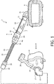
- System 2 adapted to provide a regimen of respiratory therapy to a patient according to a non-claimed example is generally shown in FIG. 1 .
- System 2 includes a pressure generating device 4, a delivery conduit assembly 6 (described in detail herein), and a patient interface device 8 including an elbow conduit 10 fluidly coupled to delivery conduit assembly 6.
- Pressure generating device 4 is structured to generate a flow of breathing gas and may include, without limitation, ventilators, constant pressure support devices (such as a continuous positive airway pressure device, or CPAP device), variable pressure devices (e.g., BiPAP®, Bi-Flex®, or C-FlexTM devices manufactured and distributed by Philips Respironics of Murrysville, Pennsylvania), and auto-titration pressure support devices.
- Delivery conduit assembly 6 is structured to communicate the flow of breathing gas from pressure generating device 4 to patient interface device 8.
- delivery conduit assembly 6 is a heated delivery assembly that also allows for inclusion of an inline accessory 7 (such as, without limitation, an oxygen enrichment adapter, a pressure valve, a bacteria filter, or any other suitable accessory device that may be used in the patient circuit of a respiratory therapy device), shown schematically in FIG. 1 , in the flow path from pressure generating device 4 to patient interface device 8.
- an inline accessory 7 such as, without limitation, an oxygen enrichment adapter, a pressure valve, a bacteria filter, or any other suitable accessory device that may be used in the patient circuit of a respiratory therapy device
- patient interface 8 is a nasal/oral mask structured to cover the nose and mouth of the patient.
- any type of patient interface device 8 such as, without limitation, a nasal mask that covers the patient's nose, a nasal cushion having nasal prongs that are received within the patient's nares, or a full face mask that covers the patient's face, which facilitates the delivery of the flow of breathing gas to, and the removal of a flow of exhalation gas from, the airway of a patient may be used.
- patient interface 8 includes a flexible cushion 16, a rigid or semi-rigid shell 18, and a forehead support 20.
- Straps (not shown) of a headgear component may be attached to shell 18 and forehead support 20 to secure patient interface device 8 to the patient's head.
- An opening in shell 18 to which elbow conduit 10 is coupled allows the flow of breathing gas from pressure generating device 4 to be communicated to an interior space defined by shell 18 and cushion 16, and then, to the airway of a patient.
- the opening in shell 18 also allows the flow of exhalation gas (from the airway of such a patient) to be communicated to an exhaust assembly 12 provided on elbow conduit 10.
- delivery conduit assembly 6 includes a heated tube assembly 22 that is directly fluidly coupled to a first end of an inline accessory adapter 24.
- Delivery conduit assembly 6 further includes inline accessory 7.
- a first end of inline accessory 7 is directly fluidly coupled to a second end of inline accessory adapter 24, and a second end of inline accessory 7 is directly fluidly coupled to heated tube capable outlet port 26 of pressure generating device 4.
- inline accessory adapter 24 is structured to enable the required electrical connection to be made between heated tube capable outlet port 26 and heated tube assembly 22 while simultaneously allowing inline accessory 7 to be inserted into the flow path.
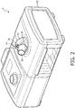
- FIG. 2 is an isometric view of pressure generating device 4 according to a non-claimed example.
- pressure generating device 4 includes a main housing 28 which houses the main components of pressure generating device 4 (e.g., the flow generator (blower), valve(s), sensors, control electronics, etc.).
- Outlet port 26 is coupled to the flow generator and extends from the top side of main housing 28.
- Outlet port 26 includes a tubular port member 30, which in the illustrated example is a standard male iso conical fitting, and a port housing 32 which houses an electrical connector 34.
- Electrical connector 34 is coupled to a power supply and/or other electronics (not shown) provided within main housing 28.
- Port housing 32 further includes slot members 33, the purpose of which is described elsewhere herein.
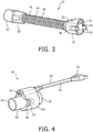
- FIG. 3 is an isometric view of heated tube assembly 22 according to a non-claimed example.
- heated tube assembly 22 includes a proximal end 36, a distal end 38, and heated tubing 40 provided between proximal end 36 and distal end 38.
- Distal end 38 is provided with a coupling member 42 structured to be fluidly coupled to elbow conduit 10, either directly or through intermediate tubing.
- Heated tubing 40 includes a central tubular member 44 surrounded by a helical heating element 46.
- Proximal end 36 is provided with a coupling member 48 that includes a tubular port member 50, which in the illustrated example is a standard female iso conical fitting, and a port housing 52 which houses an electrical connector 54.
- Electrical connector 54 is operatively coupled to heating element 46 of heated tubing 40 to provide power and/or control signals thereto.
- Port housing 52 also includes tab members 53 which are structured to be received within slot members 33 when an inline accessory as described herein is not being used.
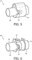
- FIG. 4 is an isometric view of inline accessory adapter 24 according to a non-claimed example.
- inline accessory adapter 24 includes a fluid coupling member 56 and a jumper wire harness assembly 58.
- Fluid coupling member 56 is structured to provide a fluid connection between proximal end 36 of heated tube assembly 22 and inline accessory 7
- jumper wire harness assembly 58 is structured to provide an electrical connection between heating element 46 of heated tube assembly 22 and outlet port 26 of pressure generating device 4.
- FIG. 5 is an isometric view of fluid coupling member 56 according to a non-claimed example.
- Fluid coupling member 56 includes a central coupling member 60 surrounded by a housing member 62.
- FIG. 6 is an isometric view of central coupling member 60 according to a non-claimed example.
- central coupling member 60 includes a first end 64 having a tubular port member 66, which in the illustrated example is a standard male iso conical fitting, and a second end 68 having a tubular port member 70, which in the illustrated example is a standard female iso conical fitting.
- Central coupling member 60 also includes a connector housing 72 for receiving and holding a connector member of jumper wire harness assembly 58, and slot members 63 for receiving and mating with tab members 53 of heated tube assembly 22.
- FIG. 7 is an isometric view of jumper wire harness assembly 58 according to a non-claimed example.
- Jumper wire harness assembly 58 includes a cable member 74 comprising a number of wires, a first electrical connector 76 provided at a first end of cable member 74, and a second electrical connector 78 provided at a second end of cable member 74.
- Inline accessory adapter 24 is assembled by inserting the first end of cable member 74 into housing member 62 in a manner wherein first electrical connector 76 is received within connector housing 72 of central coupling member 60.
- inline accessory adapter 24 is coupled to proximal end 36 of heated tube assembly 22. More specifically, tubular port member 66 of inline accessory adapter 24 is coupled to tubular port member 50 of heated tube assembly 22 and tab members 53 are inserted into slot member 63. In addition, electrical connector 54 of heated tube assembly 22 is coupled to first electrical connector 76 provided at the first end of cable member 74 of inline accessory adapter 24. Next, the first end of inline accessory 7 is fluidly coupled to tubular port member 70 of inline accessory adapter 24. In the example, inline accessory 7 has a male fitting 9 that is coupled to tubular port member 70.
- inline accessory 7 is then fluidly coupled to tubular port member 30 of outlet port 26.
- inline accessory 7 has a female fitting 11 that is coupled to tubular port member 30.
- heated tube assembly 22 being fluidly coupled to outlet port 26 of pressure generating device 4 through inline accessory adapter 24.
- second electrical connector 78 provided at the second end of cable member 74 of inline accessory adapter 24 is coupled to electrical connector 34 of outlet port 26.
- heating element 46 of heated tube assembly 22 being electrically coupled to outlet port 26 of pressure generating device 4 (and thus the power supply of pressure generating device 4) through inline accessory adapter 24.
- inline accessory adapter 24 as just described provides an easy to use a mechanism for enabling the required electrical connection to be made between heated tube capable outlet port 26 and heated tube assembly 22 while simultaneously allowing inline accessory 7 to be inserted into the flow path to the user.
- FIG. 8 is an isometric view of an enrichment adapter 80 according to an exemplary embodiment of the present invention.
- Enrichment adapter 80 may be substituted for inline accessory adapter 24 and inline accessory 7 in delivery conduit assembly 6 of FIG. 1 to allow oxygen or another supplemental gas to be added to the flow path to patient interface device 8 while at the same time allowing an electrical connection to heated tube assembly 22 from outlet port 26 to be made.
- Enrichment adapter 80 includes a central adapter assembly 82 surrounded by a housing member 108.
- FIGS. 9 and 10 are front and rear isometric views, respectively, of central adapter assembly 82 in an exemplary embodiment.
- central adapter assembly 82 includes a first end 84, a second end 86, and a wire harness assembly 98.
- Second end 86 is similar in structure to the proximal end 36 of heated tube assembly 22, and includes a tubular port member 88 (which in the illustrated embodiment is a standard female iso conical fitting) and tab members 89 structured to mate with slot members 33 of outlet port 26.
- tubular port member 88 which in the illustrated embodiment is a standard female iso conical fitting
- tab members 89 structured to mate with slot members 33 of outlet port 26.
- second end 86 is structured to hold a first electrical connector of 100 of a wire harness assembly 98 to enable second end 86 to be fluidly and electrically coupled to outlet port 26 of pressure generating device 4.
- First end 84 includes a coupling member 92 that has a tubular port member 94, which in the illustrated embodiment is a standard male iso conical fitting, a gas inlet port 96 providing access to the internal chamber defined by coupling member 92 to allow supplemental gas, such as oxygen, to be introduced into the flow path to patient interface device 8, a connector housing 102 for receiving and holding a second connector member 104 of wire harness assembly 98, and slot members 103 structured to mate with tab members 53 of heated tube assembly.
- first end 84 is structured to be fluidly and electrically coupled to the proximal end 36 of heated tube assembly 22.
- Second end 86 in the illustrated exemplary embodiment further includes a backflow prevention pressure valve 106 structured to prevent the backflow of supplemental gas into pressure generating device 4 when pressure generating device 4 is not operating.
- enrichment adapter 80 as just described is a device that may be inserted in between heated tube assembly 22 and outlet port 26 which, when so inserted, simultaneously provides (i) a main fluid path from pressure generating device 4 to heated tube assembly 22, (ii) a secondary path by which supplemental gas may be introduced into the main flow path, and (iii) electrical connection to heated tube assembly 22 from outlet port 26 by way of a jumper in the form of wire harness assembly 98.
- inline accessory adapter 24 and enrichment adapter 80 are described as being used with heated tube assembly 22, it will be understood that the present invention is not limited to use with only heated tubes. Rather, inline accessory adapter 24 and enrichment adapter 80 may be used with any type of electrical tube assembly to which an electrical connection must be made, such as, without limitation, an electrical tube assembly that includes one or more wires for carrying an electrical signal from a patient interface device to a base unit and/or from a base unit to a patient interface device.
Landscapes
- Health & Medical Sciences (AREA)
- Pulmonology (AREA)
- Engineering & Computer Science (AREA)
- General Health & Medical Sciences (AREA)
- Veterinary Medicine (AREA)
- Biomedical Technology (AREA)
- Heart & Thoracic Surgery (AREA)
- Hematology (AREA)
- Life Sciences & Earth Sciences (AREA)
- Animal Behavior & Ethology (AREA)
- Anesthesiology (AREA)
- Public Health (AREA)
- Emergency Medicine (AREA)
- Otolaryngology (AREA)
- Bioinformatics & Cheminformatics (AREA)
- Respiratory Apparatuses And Protective Means (AREA)
- Infusion, Injection, And Reservoir Apparatuses (AREA)
- Pipe Accessories (AREA)
- Massaging Devices (AREA)
- Percussion Or Vibration Massage (AREA)
- Measurement Of The Respiration, Hearing Ability, Form, And Blood Characteristics Of Living Organisms (AREA)
Claims (10)
- Appareil adaptateur d'enrichissement (80) pour un système de thérapie respiratoire (2) ayant un dispositif de génération de pression (4) et un ensemble de tube électrique (22) couplés à un dispositif d'interface patient (8) et configurés pour, en utilisation, fournir un flux de gaz respiratoire généré au niveau du dispositif de génération de pression vers le dispositif d'interface patient, l'appareil adaptateur comprenant:un ensemble de fils (98) ayant: un premier connecteur électrique (104) structuré pour être, en utilisation, couplé électriquement à l'ensemble de tube électrique (22); et un second connecteur électrique (100) structuré pour être, en utilisation, couplé électriquement au dispositif de génération de pression (4), l'ensemble de fils (98) étant structuré pour fournir une connexion entre l'ensemble de tube électrique (22) et le dispositif de génération de pression (4) via le premier connecteur électrique et le second connecteur électrique;une première extrémité (84) ayant un premier élément d'orifice (94) structuré pour être couplé de manière fluidique à l'ensemble de tube électrique (22) , la première extrémité étant configurée pour maintenir le premier connecteur électrique (104); etune seconde extrémité (86) ayant un second élément d'orifice (88) structuré pour recevoir un flux de gaz respiratoire généré par le dispositif de génération de pression (4), la seconde extrémité étant configurée pour maintenir le second connecteur électrique (100),l'appareil adaptateur (80) étant structuré pour fournir le flux de gaz respiratoire à l'ensemble de tube électrique (22) à partir du second élément d'orifice (88), via un chemin d'écoulement principal qui relie le second élément d'orifice (88) intérieurement au un premier élément d'orifice (94), et à travers le premier élément d'orifice (94);où le premier élément d'orifice (94) est prévu comme partie d'un élément de couplage (92) ayant une chambre interne qui fait partie du chemin d'écoulement principal,où l'élément de couplage (92) a un orifice d'entrée de gaz (96) fournissant un accès à la chambre interne pour, en utilisation, permettre à un gaz supplémentaire d'être introduit dans le chemin d'écoulement principal à ajouter au flux de gaz respiratoire,où l'ensemble de fils (98) est un ensemble d'harnais de fils de raccordement, etoù le premier élément d'orifice (94) est un élément d'orifice tubulaire et le second élément d'orifice (88) est un élément d'orifice tubulaire.
- Appareil adaptateur selon la revendication 1, dans lequel l'ensemble de tube électrique (22) est un ensemble de tube chauffé.
- Appareil adaptateur selon la revendication 1 ou 2, dans lequel la seconde extrémité (86) est couplée à l'élément de couplage (92), dans lequel le second connecteur électrique (100) est structuré pour être couplé électriquement à un orifice de sortie (26) du dispositif de génération de pression (4), et dans lequel le second élément d'orifice (88) est structuré pour être couplé de manière fluidique à l'orifice de sortie (26) du dispositif de génération de pression (4).
- Appareil adaptateur selon l'une quelconque des revendications 1 à 3, dans lequel la seconde extrémité (86) comprend une soupape de pression anti-retour (106).
- Appareil adaptateur selon l'une quelconque des revendications 1 à 4, comprenant en outre:un ensemble adaptateur central (82); etun élément de boîtier (108) entourant l'ensemble adaptateur central (82);où la première extrémité (84), la seconde extrémité (86) et l'ensemble de fils (98) font partie de l'ensemble adaptateur central (82).
- Système de thérapie respiratoire (2), comprenant:un dispositif de génération de pression (4) structuré pour générer un flux de gaz respiratoire;un dispositif d'interface patient (8);un ensemble de tube électrique (22) couplé au dispositif d'interface patient (8); etun appareil adaptateur selon la revendication 1, configuré pour être couplé au dispositif de génération de pression (4) et à l'ensemble de tube électrique (22).
- Système de thérapie respiratoire selon la revendication 6, dans lequel l'ensemble de tube électrique (22) est un ensemble de tube chauffé.
- Système de thérapie respiratoire selon la revendication 6 ou 7, dans lequel la seconde extrémité (86) de l'appareil adaptateur est couplée à l'élément de couplage (92), dans lequel le second connecteur électrique (100) est configuré pour être couplé électriquement à un orifice de sortie (26) du dispositif de génération de pression (4), et dans lequel le second élément d'orifice (88) est configuré pour être couplé de manière fluidique à l'orifice de sortie (26) du dispositif de génération de pression (4).
- Système de thérapie respiratoire selon l'une quelconque des revendications 6 à 8, dans lequel la seconde extrémité (86) comprend une soupape de pression anti-retour (106).
- Système de thérapie respiratoire selon l'une quelconque des revendications 6 à 9, dans lequel l'appareil adaptateur comprend en outre:un ensemble adaptateur central (82); etun élément de boîtier (108) entourant l'ensemble adaptateur central (82);où la première extrémité (84), la seconde extrémité (86) et l'ensemble de fils (98) sont partie de l'ensemble adaptateur central (82).
Applications Claiming Priority (3)
| Application Number | Priority Date | Filing Date | Title |
|---|---|---|---|
| US201261740217P | 2012-12-20 | 2012-12-20 | |
| EP13824204.5A EP2934644B1 (fr) | 2012-12-20 | 2013-12-17 | Adaptateur intégré destiné à un dispositif de thérapie respiratoire |
| PCT/IB2013/061037 WO2014097145A1 (fr) | 2012-12-20 | 2013-12-17 | Adaptateur intégré destiné à un dispositif de thérapie respiratoire |
Related Parent Applications (2)
| Application Number | Title | Priority Date | Filing Date |
|---|---|---|---|
| EP13824204.5A Division EP2934644B1 (fr) | 2012-12-20 | 2013-12-17 | Adaptateur intégré destiné à un dispositif de thérapie respiratoire |
| EP13824204.5A Division-Into EP2934644B1 (fr) | 2012-12-20 | 2013-12-17 | Adaptateur intégré destiné à un dispositif de thérapie respiratoire |
Publications (2)
| Publication Number | Publication Date |
|---|---|
| EP3034122A1 EP3034122A1 (fr) | 2016-06-22 |
| EP3034122B1 true EP3034122B1 (fr) | 2020-09-16 |
Family
ID=50001064
Family Applications (2)
| Application Number | Title | Priority Date | Filing Date |
|---|---|---|---|
| EP13824204.5A Active EP2934644B1 (fr) | 2012-12-20 | 2013-12-17 | Adaptateur intégré destiné à un dispositif de thérapie respiratoire |
| EP15200001.4A Active EP3034122B1 (fr) | 2012-12-20 | 2013-12-17 | Adaptateur en ligne pour un dispositif de thérapie respiratoire |
Family Applications Before (1)
| Application Number | Title | Priority Date | Filing Date |
|---|---|---|---|
| EP13824204.5A Active EP2934644B1 (fr) | 2012-12-20 | 2013-12-17 | Adaptateur intégré destiné à un dispositif de thérapie respiratoire |
Country Status (8)
| Country | Link |
|---|---|
| US (1) | US9974917B2 (fr) |
| EP (2) | EP2934644B1 (fr) |
| JP (1) | JP6378199B2 (fr) |
| CN (1) | CN104870042B (fr) |
| AU (1) | AU2013365825B2 (fr) |
| BR (1) | BR112015014324B1 (fr) |
| RU (1) | RU2657953C2 (fr) |
| WO (1) | WO2014097145A1 (fr) |
Families Citing this family (46)
| Publication number | Priority date | Publication date | Assignee | Title |
|---|---|---|---|---|
| FR2978920B1 (fr) | 2011-08-10 | 2016-01-01 | Fisher & Paykel Healthcare Ltd | Raccord de conduit pour un dispositif respiratoire pour patient |
| USD747471S1 (en) | 2012-08-10 | 2016-01-12 | Fisher & Paykel Healthcare Limited | Connector |
| USD738489S1 (en) | 2013-05-31 | 2015-09-08 | Resmed Limited | Positive airway pressure delivery console |
| USD738488S1 (en) | 2013-05-31 | 2015-09-08 | Resmed Limited | Positive airway pressure delivery console |
| JP1525591S (fr) | 2014-02-19 | 2018-05-21 | ||
| USD743556S1 (en) | 2014-02-19 | 2015-11-17 | Resmed Limited | Positive airway pressure delivery console |
| USD762843S1 (en) | 2014-03-18 | 2016-08-02 | Resmed Limited | Air delivery tube |
| USD760258S1 (en) | 2014-05-30 | 2016-06-28 | Resmed Limited | Display screen with graphical user interface |
| EP4147738B1 (fr) * | 2014-07-07 | 2025-12-24 | Fisher & Paykel Healthcare Limited | Tubes médicaux et connecteurs pour systèmes de distribution de gaz |
| USD809124S1 (en) | 2014-09-12 | 2018-01-30 | Resmed Limited | Pressurized air delivery console |
| USD790683S1 (en) | 2015-03-11 | 2017-06-27 | Resmed Limited | Pressurized air delivery console |
| WO2016157101A1 (fr) * | 2015-03-31 | 2016-10-06 | Fisher & Paykel Healthcare Limited | Appareil destiné à être utilisé dans un système d'assistance respiratoire |
| KR102650815B1 (ko) * | 2015-09-04 | 2024-03-26 | 피셔 앤 페이켈 핼스케어 리미티드 | 도관용 커넥터들 |
| USD807995S1 (en) * | 2015-09-22 | 2018-01-16 | Fisher & Paykel Healthcare Limited | Circuit kit for a humidifier |
| USD841147S1 (en) * | 2015-09-30 | 2019-02-19 | Fisher & Paykel Healthcare Limited | Circuit kit for a humidifier |
| USD805630S1 (en) * | 2016-02-02 | 2017-12-19 | Resmed Limited | Air delivery tube |
| USD809656S1 (en) | 2016-06-10 | 2018-02-06 | Fisher & Paykel Healthcare Limited | Connector for a breathing circuit |
| USD841148S1 (en) * | 2016-07-21 | 2019-02-19 | Fisher & Paykel Healthcare Limited | Breathing tube |
| US10953185B2 (en) * | 2017-03-31 | 2021-03-23 | Koninklijke Philips N.V. | Moisture wicking conduit and system |
| USD895788S1 (en) * | 2018-01-30 | 2020-09-08 | Inovytec Medical Solutions Ltd. | Patient circuit for gas delivery |
| EP3768362A4 (fr) * | 2018-03-20 | 2021-12-15 | Ideya Labs, LLC | Système de distribution d'huile par pression positive des voies respiratoires |
| DE102018126886A1 (de) * | 2018-10-19 | 2020-04-23 | Eugen Forschner Gmbh | Verbindungsanordnung |
| CN121971768A (zh) * | 2018-11-05 | 2026-05-05 | 费雪派克医疗保健有限公司 | 呼吸辅助设备和/或其部件 |
| JP6979148B1 (ja) * | 2018-11-16 | 2021-12-08 | コーニンクレッカ フィリップス エヌ ヴェKoninklijke Philips N.V. | 圧力支援システムの弁 |
| USD958968S1 (en) * | 2018-11-28 | 2022-07-26 | Fisher & Paykel Healthcare Limited | Breathing tube with mesh |
| USD921900S1 (en) | 2018-12-19 | 2021-06-08 | ResMed Pty Ltd | Humidification tub |
| JP7613812B2 (ja) * | 2019-07-08 | 2025-01-15 | フィッシャー アンド ペイケル ヘルスケア リミテッド | 呼吸回路のための医療用チューブ及びコネクタ |
| WO2021010027A1 (fr) * | 2019-07-12 | 2021-01-21 | 株式会社村田製作所 | Dispositif cpap |
| US10737049B1 (en) | 2019-08-05 | 2020-08-11 | Dynasthetics, Llc | Apparatus for connecting oxygen delivery control instrument to patient delivery device |
| USD1006981S1 (en) | 2019-09-06 | 2023-12-05 | Fisher & Paykel Healthcare Limited | Breathing conduit |
| USD948027S1 (en) | 2019-09-10 | 2022-04-05 | Fisher & Paykel Healthcare Limited | Connector for a breathing conduit |
| US20220401673A1 (en) * | 2019-10-31 | 2022-12-22 | Resmed Sensor Technologies Limited | Systems and methods for injecting substances into a respiratory system |
| USD944939S1 (en) * | 2020-02-26 | 2022-03-01 | Soclean, Inc. | Connector for a sanitizing machine |
| USD944938S1 (en) * | 2020-02-26 | 2022-03-01 | Soclean, Inc. | Connector for a sanitizing machine |
| USD949295S1 (en) * | 2020-02-26 | 2022-04-19 | Soclean Inc. | Connector for a sanitizing machine |
| USD957589S1 (en) * | 2020-02-26 | 2022-07-12 | Soclean, Inc. | Connector for a sanitizing machine |
| USD944941S1 (en) * | 2020-02-27 | 2022-03-01 | Soclean, Inc. | Connector for a sanitizing machine |
| USD940861S1 (en) | 2020-03-03 | 2022-01-11 | Fisher & Paykel Healthcare Limited | Connector for a respiratory system conduit |
| JP7723089B2 (ja) * | 2020-11-03 | 2025-08-13 | レスメド・プロプライエタリー・リミテッド | 呼吸圧力治療デバイス |
| USD974551S1 (en) | 2020-12-09 | 2023-01-03 | Fisher & Paykel Healthcare Limited | Connector assembly and connector |
| US11986592B2 (en) | 2021-05-14 | 2024-05-21 | Dynasthetics, Llc | Electronic firebreak systems and methods for use with oxygen delivery device |
| USD1073919S1 (en) | 2021-05-17 | 2025-05-06 | Fisher & Paykel Healthcare Limited | Respiratory system conduit with connector |
| USD995758S1 (en) | 2021-06-11 | 2023-08-15 | Fisher & Paykel Healthcare Limited | Tube assembly and connector |
| USD1064254S1 (en) | 2021-10-21 | 2025-02-25 | Hamilton Medical Ag | Breathing tube for medical respiratory apparatus |
| CN114848993B (zh) * | 2022-06-06 | 2025-09-02 | 深圳市普博医疗科技股份有限公司 | 流体连接装置以及通气设备 |
| US12551650B2 (en) | 2024-03-01 | 2026-02-17 | Exceleron Medical, LLC | Respiratory apparatus airflow tube |
Family Cites Families (21)
| Publication number | Priority date | Publication date | Assignee | Title |
|---|---|---|---|---|
| JPH08317983A (ja) * | 1995-03-17 | 1996-12-03 | Teijin Ltd | 呼吸用気体供給装置 |
| JP2001514941A (ja) * | 1997-08-14 | 2001-09-18 | レスメッド・リミテッド | オンディマンドの追加呼吸に適したガスを供給するための装置及び方法 |
| SE9704663D0 (sv) * | 1997-12-15 | 1997-12-15 | Siemens Elema Ab | Ventilator system |
| DE19958296C1 (de) * | 1999-12-03 | 2001-09-20 | Map Gmbh | Beheizbarer Atemgasschlauch |
| SE0000605D0 (sv) * | 2000-02-24 | 2000-02-24 | Siemens Elema Ab | Conduit for connecting a fluid transfer device to a patient |
| US7120354B2 (en) * | 2000-03-21 | 2006-10-10 | Fisher & Paykel Healthcare Limited | Gases delivery conduit |
| DE10134725A1 (de) * | 2001-07-17 | 2003-02-06 | Weinmann G Geraete Med | Vorrichtung zur Filterung von Atemluft |
| DE102005000922A1 (de) * | 2005-01-07 | 2006-07-20 | Seleon Gmbh | Luftbrille, Nasenstück, Y-Stück sowie Verfahren |
| US8522782B2 (en) | 2005-09-12 | 2013-09-03 | Mergenet Medical, Inc. | High flow therapy device utilizing a non-sealing respiratory interface and related methods |
| CN101365509A (zh) * | 2005-12-14 | 2009-02-11 | 莫哲奈特医疗公司 | 高流量治疗装置 |
| CN110141752B (zh) * | 2006-11-08 | 2022-03-04 | 瑞思迈私人有限公司 | 在呼吸装置中使用的导管 |
| CN103933651B (zh) * | 2006-11-08 | 2019-06-04 | 瑞思迈有限公司 | 在呼吸装置中使用的导管 |
| US8770198B2 (en) | 2006-12-21 | 2014-07-08 | Resmed Limited | Connector |
| WO2008105257A1 (fr) * | 2007-02-26 | 2008-09-04 | Nec Corporation | Circuit haute fréquence |
| CN101808689B (zh) * | 2007-08-14 | 2013-10-09 | 柔性塑料集团 | 呼吸系统 |
| CN102196837B (zh) | 2008-08-22 | 2015-09-09 | 呼吸科技公司 | 利用开放的气道界面提供机械通气的方法和装置 |
| AU2010206053B2 (en) * | 2009-07-31 | 2014-08-07 | ResMed Pty Ltd | Wire Heated Tube with Temperature Control System, Tube Type Detection, and Active Over Temperature Protection for Humidifier for Respiratory Apparatus |
| WO2012031315A1 (fr) * | 2010-09-06 | 2012-03-15 | Resmed Limited | Procédés et appareil pour prévenir la condensation |
| US9717873B2 (en) | 2011-05-20 | 2017-08-01 | Koninklijke Philips N.V. | Rotating electrical connector ADN respiratory gas delivery system employing same |
| EP2731632B1 (fr) * | 2011-07-15 | 2017-08-30 | SoClean, Inc. | Apparaeil CPAP avec generateur d'ozone |
| EP3701991A1 (fr) * | 2012-04-05 | 2020-09-02 | Fisher & Paykel Healthcare Limited | Appareil d'assistance respiratoire présentant des caractéristiques d'aptitude à l'usage |
-
2013
- 2013-12-17 AU AU2013365825A patent/AU2013365825B2/en active Active
- 2013-12-17 US US14/646,740 patent/US9974917B2/en active Active
- 2013-12-17 JP JP2015548835A patent/JP6378199B2/ja active Active
- 2013-12-17 EP EP13824204.5A patent/EP2934644B1/fr active Active
- 2013-12-17 RU RU2015129059A patent/RU2657953C2/ru active
- 2013-12-17 CN CN201380067180.9A patent/CN104870042B/zh active Active
- 2013-12-17 WO PCT/IB2013/061037 patent/WO2014097145A1/fr not_active Ceased
- 2013-12-17 BR BR112015014324-5A patent/BR112015014324B1/pt active IP Right Grant
- 2013-12-17 EP EP15200001.4A patent/EP3034122B1/fr active Active
Non-Patent Citations (1)
| Title |
|---|
| None * |
Also Published As
| Publication number | Publication date |
|---|---|
| US20150306332A1 (en) | 2015-10-29 |
| CN104870042A (zh) | 2015-08-26 |
| EP2934644A1 (fr) | 2015-10-28 |
| JP2016501608A (ja) | 2016-01-21 |
| JP6378199B2 (ja) | 2018-08-22 |
| WO2014097145A1 (fr) | 2014-06-26 |
| CN104870042B (zh) | 2019-01-22 |
| BR112015014324B1 (pt) | 2021-05-18 |
| EP2934644B1 (fr) | 2019-02-27 |
| AU2013365825A1 (en) | 2015-08-06 |
| BR112015014324A2 (pt) | 2017-07-11 |
| RU2657953C2 (ru) | 2018-06-18 |
| AU2013365825B2 (en) | 2018-07-12 |
| RU2015129059A (ru) | 2017-01-26 |
| EP3034122A1 (fr) | 2016-06-22 |
| US9974917B2 (en) | 2018-05-22 |
Similar Documents
| Publication | Publication Date | Title |
|---|---|---|
| EP2934644B1 (fr) | Adaptateur intégré destiné à un dispositif de thérapie respiratoire | |
| US12440633B2 (en) | Patient interface with integrated jet pump | |
| US10617838B2 (en) | Modular patient interface device with chamber and nasal pillows assembly | |
| EP2931349B1 (fr) | Dispositif d'accouplement rotatif | |
| EP2393539B1 (fr) | Dispositif d'interface nasale | |
| US9717873B2 (en) | Rotating electrical connector ADN respiratory gas delivery system employing same | |
| US10737052B2 (en) | Fluid coupling member including valve member | |
| US20170319808A1 (en) | Patient interface device with drawstring adjustment | |
| US11090456B2 (en) | Liquid removal in a patient interface assembly | |
| US10507299B2 (en) | Releasable elbow connector | |
| WO2013050893A1 (fr) | Ensemble frontal d'alimentation en gaz pour système d'interface patient | |
| EP4536330A1 (fr) | Agencement de diffuseur d'échappement et masque cpap le comprenant | |
| WO2012073147A1 (fr) | Dispositif d'interface patient présentant un conduit de coude multiaxe |
Legal Events
| Date | Code | Title | Description |
|---|---|---|---|
| PUAI | Public reference made under article 153(3) epc to a published international application that has entered the european phase |
Free format text: ORIGINAL CODE: 0009012 |
|
| AC | Divisional application: reference to earlier application |
Ref document number: 2934644 Country of ref document: EP Kind code of ref document: P |
|
| AK | Designated contracting states |
Kind code of ref document: A1 Designated state(s): AL AT BE BG CH CY CZ DE DK EE ES FI FR GB GR HR HU IE IS IT LI LT LU LV MC MK MT NL NO PL PT RO RS SE SI SK SM TR |
|
| STAA | Information on the status of an ep patent application or granted ep patent |
Free format text: STATUS: REQUEST FOR EXAMINATION WAS MADE |
|
| 17P | Request for examination filed |
Effective date: 20161222 |
|
| RBV | Designated contracting states (corrected) |
Designated state(s): AL AT BE BG CH CY CZ DE DK EE ES FI FR GB GR HR HU IE IS IT LI LT LU LV MC MK MT NL NO PL PT RO RS SE SI SK SM TR |
|
| STAA | Information on the status of an ep patent application or granted ep patent |
Free format text: STATUS: EXAMINATION IS IN PROGRESS |
|
| 17Q | First examination report despatched |
Effective date: 20180612 |
|
| RAP1 | Party data changed (applicant data changed or rights of an application transferred) |
Owner name: KONINKLIJKE PHILIPS N.V. |
|
| GRAP | Despatch of communication of intention to grant a patent |
Free format text: ORIGINAL CODE: EPIDOSNIGR1 |
|
| STAA | Information on the status of an ep patent application or granted ep patent |
Free format text: STATUS: GRANT OF PATENT IS INTENDED |
|
| RIC1 | Information provided on ipc code assigned before grant |
Ipc: A61M 16/10 20060101ALI20200324BHEP Ipc: A61M 16/20 20060101ALN20200324BHEP Ipc: A61M 16/12 20060101ALN20200324BHEP Ipc: A61M 15/08 20060101ALI20200324BHEP Ipc: A61M 16/00 20060101ALN20200324BHEP Ipc: A61M 39/10 20060101ALN20200324BHEP Ipc: A61M 16/08 20060101AFI20200324BHEP Ipc: A61M 16/06 20060101ALN20200324BHEP |
|
| INTG | Intention to grant announced |
Effective date: 20200408 |
|
| GRAS | Grant fee paid |
Free format text: ORIGINAL CODE: EPIDOSNIGR3 |
|
| GRAA | (expected) grant |
Free format text: ORIGINAL CODE: 0009210 |
|
| STAA | Information on the status of an ep patent application or granted ep patent |
Free format text: STATUS: THE PATENT HAS BEEN GRANTED |
|
| AC | Divisional application: reference to earlier application |
Ref document number: 2934644 Country of ref document: EP Kind code of ref document: P |
|
| AK | Designated contracting states |
Kind code of ref document: B1 Designated state(s): AL AT BE BG CH CY CZ DE DK EE ES FI FR GB GR HR HU IE IS IT LI LT LU LV MC MK MT NL NO PL PT RO RS SE SI SK SM TR |
|
| REG | Reference to a national code |
Ref country code: GB Ref legal event code: FG4D |
|
| REG | Reference to a national code |
Ref country code: CH Ref legal event code: EP |
|
| REG | Reference to a national code |
Ref country code: DE Ref legal event code: R096 Ref document number: 602013072675 Country of ref document: DE |
|
| REG | Reference to a national code |
Ref country code: IE Ref legal event code: FG4D |
|
| REG | Reference to a national code |
Ref country code: AT Ref legal event code: REF Ref document number: 1313588 Country of ref document: AT Kind code of ref document: T Effective date: 20201015 |
|
| PG25 | Lapsed in a contracting state [announced via postgrant information from national office to epo] |
Ref country code: GR Free format text: LAPSE BECAUSE OF FAILURE TO SUBMIT A TRANSLATION OF THE DESCRIPTION OR TO PAY THE FEE WITHIN THE PRESCRIBED TIME-LIMIT Effective date: 20201217 Ref country code: NO Free format text: LAPSE BECAUSE OF FAILURE TO SUBMIT A TRANSLATION OF THE DESCRIPTION OR TO PAY THE FEE WITHIN THE PRESCRIBED TIME-LIMIT Effective date: 20201216 Ref country code: FI Free format text: LAPSE BECAUSE OF FAILURE TO SUBMIT A TRANSLATION OF THE DESCRIPTION OR TO PAY THE FEE WITHIN THE PRESCRIBED TIME-LIMIT Effective date: 20200916 Ref country code: SE Free format text: LAPSE BECAUSE OF FAILURE TO SUBMIT A TRANSLATION OF THE DESCRIPTION OR TO PAY THE FEE WITHIN THE PRESCRIBED TIME-LIMIT Effective date: 20200916 Ref country code: BG Free format text: LAPSE BECAUSE OF FAILURE TO SUBMIT A TRANSLATION OF THE DESCRIPTION OR TO PAY THE FEE WITHIN THE PRESCRIBED TIME-LIMIT Effective date: 20201216 Ref country code: HR Free format text: LAPSE BECAUSE OF FAILURE TO SUBMIT A TRANSLATION OF THE DESCRIPTION OR TO PAY THE FEE WITHIN THE PRESCRIBED TIME-LIMIT Effective date: 20200916 |
|
| REG | Reference to a national code |
Ref country code: AT Ref legal event code: MK05 Ref document number: 1313588 Country of ref document: AT Kind code of ref document: T Effective date: 20200916 |
|
| REG | Reference to a national code |
Ref country code: NL Ref legal event code: MP Effective date: 20200916 |
|
| PG25 | Lapsed in a contracting state [announced via postgrant information from national office to epo] |
Ref country code: RS Free format text: LAPSE BECAUSE OF FAILURE TO SUBMIT A TRANSLATION OF THE DESCRIPTION OR TO PAY THE FEE WITHIN THE PRESCRIBED TIME-LIMIT Effective date: 20200916 Ref country code: LV Free format text: LAPSE BECAUSE OF FAILURE TO SUBMIT A TRANSLATION OF THE DESCRIPTION OR TO PAY THE FEE WITHIN THE PRESCRIBED TIME-LIMIT Effective date: 20200916 |
|
| REG | Reference to a national code |
Ref country code: LT Ref legal event code: MG4D |
|
| PG25 | Lapsed in a contracting state [announced via postgrant information from national office to epo] |
Ref country code: SM Free format text: LAPSE BECAUSE OF FAILURE TO SUBMIT A TRANSLATION OF THE DESCRIPTION OR TO PAY THE FEE WITHIN THE PRESCRIBED TIME-LIMIT Effective date: 20200916 Ref country code: RO Free format text: LAPSE BECAUSE OF FAILURE TO SUBMIT A TRANSLATION OF THE DESCRIPTION OR TO PAY THE FEE WITHIN THE PRESCRIBED TIME-LIMIT Effective date: 20200916 Ref country code: EE Free format text: LAPSE BECAUSE OF FAILURE TO SUBMIT A TRANSLATION OF THE DESCRIPTION OR TO PAY THE FEE WITHIN THE PRESCRIBED TIME-LIMIT Effective date: 20200916 Ref country code: PT Free format text: LAPSE BECAUSE OF FAILURE TO SUBMIT A TRANSLATION OF THE DESCRIPTION OR TO PAY THE FEE WITHIN THE PRESCRIBED TIME-LIMIT Effective date: 20210118 Ref country code: LT Free format text: LAPSE BECAUSE OF FAILURE TO SUBMIT A TRANSLATION OF THE DESCRIPTION OR TO PAY THE FEE WITHIN THE PRESCRIBED TIME-LIMIT Effective date: 20200916 Ref country code: NL Free format text: LAPSE BECAUSE OF FAILURE TO SUBMIT A TRANSLATION OF THE DESCRIPTION OR TO PAY THE FEE WITHIN THE PRESCRIBED TIME-LIMIT Effective date: 20200916 Ref country code: CZ Free format text: LAPSE BECAUSE OF FAILURE TO SUBMIT A TRANSLATION OF THE DESCRIPTION OR TO PAY THE FEE WITHIN THE PRESCRIBED TIME-LIMIT Effective date: 20200916 |
|
| PG25 | Lapsed in a contracting state [announced via postgrant information from national office to epo] |
Ref country code: PL Free format text: LAPSE BECAUSE OF FAILURE TO SUBMIT A TRANSLATION OF THE DESCRIPTION OR TO PAY THE FEE WITHIN THE PRESCRIBED TIME-LIMIT Effective date: 20200916 Ref country code: IS Free format text: LAPSE BECAUSE OF FAILURE TO SUBMIT A TRANSLATION OF THE DESCRIPTION OR TO PAY THE FEE WITHIN THE PRESCRIBED TIME-LIMIT Effective date: 20210116 Ref country code: AT Free format text: LAPSE BECAUSE OF FAILURE TO SUBMIT A TRANSLATION OF THE DESCRIPTION OR TO PAY THE FEE WITHIN THE PRESCRIBED TIME-LIMIT Effective date: 20200916 Ref country code: AL Free format text: LAPSE BECAUSE OF FAILURE TO SUBMIT A TRANSLATION OF THE DESCRIPTION OR TO PAY THE FEE WITHIN THE PRESCRIBED TIME-LIMIT Effective date: 20200916 Ref country code: ES Free format text: LAPSE BECAUSE OF FAILURE TO SUBMIT A TRANSLATION OF THE DESCRIPTION OR TO PAY THE FEE WITHIN THE PRESCRIBED TIME-LIMIT Effective date: 20200916 |
|
| REG | Reference to a national code |
Ref country code: DE Ref legal event code: R097 Ref document number: 602013072675 Country of ref document: DE |
|
| PG25 | Lapsed in a contracting state [announced via postgrant information from national office to epo] |
Ref country code: SK Free format text: LAPSE BECAUSE OF FAILURE TO SUBMIT A TRANSLATION OF THE DESCRIPTION OR TO PAY THE FEE WITHIN THE PRESCRIBED TIME-LIMIT Effective date: 20200916 |
|
| PLBE | No opposition filed within time limit |
Free format text: ORIGINAL CODE: 0009261 |
|
| STAA | Information on the status of an ep patent application or granted ep patent |
Free format text: STATUS: NO OPPOSITION FILED WITHIN TIME LIMIT |
|
| REG | Reference to a national code |
Ref country code: CH Ref legal event code: PL |
|
| 26N | No opposition filed |
Effective date: 20210617 |
|
| PG25 | Lapsed in a contracting state [announced via postgrant information from national office to epo] |
Ref country code: SI Free format text: LAPSE BECAUSE OF FAILURE TO SUBMIT A TRANSLATION OF THE DESCRIPTION OR TO PAY THE FEE WITHIN THE PRESCRIBED TIME-LIMIT Effective date: 20200916 Ref country code: DK Free format text: LAPSE BECAUSE OF FAILURE TO SUBMIT A TRANSLATION OF THE DESCRIPTION OR TO PAY THE FEE WITHIN THE PRESCRIBED TIME-LIMIT Effective date: 20200916 Ref country code: MC Free format text: LAPSE BECAUSE OF FAILURE TO SUBMIT A TRANSLATION OF THE DESCRIPTION OR TO PAY THE FEE WITHIN THE PRESCRIBED TIME-LIMIT Effective date: 20200916 |
|
| REG | Reference to a national code |
Ref country code: BE Ref legal event code: MM Effective date: 20201231 |
|
| PG25 | Lapsed in a contracting state [announced via postgrant information from national office to epo] |
Ref country code: IT Free format text: LAPSE BECAUSE OF FAILURE TO SUBMIT A TRANSLATION OF THE DESCRIPTION OR TO PAY THE FEE WITHIN THE PRESCRIBED TIME-LIMIT Effective date: 20200916 Ref country code: IE Free format text: LAPSE BECAUSE OF NON-PAYMENT OF DUE FEES Effective date: 20201217 Ref country code: LU Free format text: LAPSE BECAUSE OF NON-PAYMENT OF DUE FEES Effective date: 20201217 |
|
| PG25 | Lapsed in a contracting state [announced via postgrant information from national office to epo] |
Ref country code: LI Free format text: LAPSE BECAUSE OF NON-PAYMENT OF DUE FEES Effective date: 20201231 Ref country code: CH Free format text: LAPSE BECAUSE OF NON-PAYMENT OF DUE FEES Effective date: 20201231 |
|
| PG25 | Lapsed in a contracting state [announced via postgrant information from national office to epo] |
Ref country code: TR Free format text: LAPSE BECAUSE OF FAILURE TO SUBMIT A TRANSLATION OF THE DESCRIPTION OR TO PAY THE FEE WITHIN THE PRESCRIBED TIME-LIMIT Effective date: 20200916 Ref country code: MT Free format text: LAPSE BECAUSE OF FAILURE TO SUBMIT A TRANSLATION OF THE DESCRIPTION OR TO PAY THE FEE WITHIN THE PRESCRIBED TIME-LIMIT Effective date: 20200916 Ref country code: CY Free format text: LAPSE BECAUSE OF FAILURE TO SUBMIT A TRANSLATION OF THE DESCRIPTION OR TO PAY THE FEE WITHIN THE PRESCRIBED TIME-LIMIT Effective date: 20200916 |
|
| PG25 | Lapsed in a contracting state [announced via postgrant information from national office to epo] |
Ref country code: MK Free format text: LAPSE BECAUSE OF FAILURE TO SUBMIT A TRANSLATION OF THE DESCRIPTION OR TO PAY THE FEE WITHIN THE PRESCRIBED TIME-LIMIT Effective date: 20200916 |
|
| PG25 | Lapsed in a contracting state [announced via postgrant information from national office to epo] |
Ref country code: BE Free format text: LAPSE BECAUSE OF NON-PAYMENT OF DUE FEES Effective date: 20201231 |
|
| PGFP | Annual fee paid to national office [announced via postgrant information from national office to epo] |
Ref country code: GB Payment date: 20251223 Year of fee payment: 13 |
|
| PGFP | Annual fee paid to national office [announced via postgrant information from national office to epo] |
Ref country code: FR Payment date: 20251222 Year of fee payment: 13 |
|
| PGFP | Annual fee paid to national office [announced via postgrant information from national office to epo] |
Ref country code: DE Payment date: 20251229 Year of fee payment: 13 |