EP3034173A1 - Dispositif et procede de separation de particules d'un flux d'air provenant d'une cabine de peinture - Google Patents
Dispositif et procede de separation de particules d'un flux d'air provenant d'une cabine de peinture Download PDFInfo
- Publication number
- EP3034173A1 EP3034173A1 EP15003596.2A EP15003596A EP3034173A1 EP 3034173 A1 EP3034173 A1 EP 3034173A1 EP 15003596 A EP15003596 A EP 15003596A EP 3034173 A1 EP3034173 A1 EP 3034173A1
- Authority
- EP
- European Patent Office
- Prior art keywords
- exhaust air
- region
- electrodes
- air stream
- electrode
- Prior art date
- Legal status (The legal status is an assumption and is not a legal conclusion. Google has not performed a legal analysis and makes no representation as to the accuracy of the status listed.)
- Withdrawn
Links
Images

Classifications
-
- B—PERFORMING OPERATIONS; TRANSPORTING
- B03—SEPARATION OF SOLID MATERIALS USING LIQUIDS OR USING PNEUMATIC TABLES OR JIGS; MAGNETIC OR ELECTROSTATIC SEPARATION OF SOLID MATERIALS FROM SOLID MATERIALS OR FLUIDS; SEPARATION BY HIGH-VOLTAGE ELECTRIC FIELDS
- B03C—MAGNETIC OR ELECTROSTATIC SEPARATION OF SOLID MATERIALS FROM SOLID MATERIALS OR FLUIDS; SEPARATION BY HIGH-VOLTAGE ELECTRIC FIELDS
- B03C3/00—Separating dispersed particles from gases or vapour, e.g. air, by electrostatic effect
- B03C3/02—Plant or installations having external electricity supply
- B03C3/04—Plant or installations having external electricity supply dry type
-
- B—PERFORMING OPERATIONS; TRANSPORTING
- B01—PHYSICAL OR CHEMICAL PROCESSES OR APPARATUS IN GENERAL
- B01D—SEPARATION
- B01D53/00—Separation of gases or vapours; Recovering vapours of volatile solvents from gases; Chemical or biological purification of waste gases, e.g. engine exhaust gases, smoke, fumes, flue gases, aerosols
- B01D53/32—Separation of gases or vapours; Recovering vapours of volatile solvents from gases; Chemical or biological purification of waste gases, e.g. engine exhaust gases, smoke, fumes, flue gases, aerosols by electrical effects other than those provided for in group B01D61/00
- B01D53/323—Separation of gases or vapours; Recovering vapours of volatile solvents from gases; Chemical or biological purification of waste gases, e.g. engine exhaust gases, smoke, fumes, flue gases, aerosols by electrical effects other than those provided for in group B01D61/00 by electrostatic effects or by high-voltage electric fields
-
- B—PERFORMING OPERATIONS; TRANSPORTING
- B03—SEPARATION OF SOLID MATERIALS USING LIQUIDS OR USING PNEUMATIC TABLES OR JIGS; MAGNETIC OR ELECTROSTATIC SEPARATION OF SOLID MATERIALS FROM SOLID MATERIALS OR FLUIDS; SEPARATION BY HIGH-VOLTAGE ELECTRIC FIELDS
- B03C—MAGNETIC OR ELECTROSTATIC SEPARATION OF SOLID MATERIALS FROM SOLID MATERIALS OR FLUIDS; SEPARATION BY HIGH-VOLTAGE ELECTRIC FIELDS
- B03C3/00—Separating dispersed particles from gases or vapour, e.g. air, by electrostatic effect
- B03C3/017—Combinations of electrostatic separation with other processes, not otherwise provided for
-
- B—PERFORMING OPERATIONS; TRANSPORTING
- B03—SEPARATION OF SOLID MATERIALS USING LIQUIDS OR USING PNEUMATIC TABLES OR JIGS; MAGNETIC OR ELECTROSTATIC SEPARATION OF SOLID MATERIALS FROM SOLID MATERIALS OR FLUIDS; SEPARATION BY HIGH-VOLTAGE ELECTRIC FIELDS
- B03C—MAGNETIC OR ELECTROSTATIC SEPARATION OF SOLID MATERIALS FROM SOLID MATERIALS OR FLUIDS; SEPARATION BY HIGH-VOLTAGE ELECTRIC FIELDS
- B03C3/00—Separating dispersed particles from gases or vapour, e.g. air, by electrostatic effect
- B03C3/019—Post-treatment of gases
-
- B—PERFORMING OPERATIONS; TRANSPORTING
- B03—SEPARATION OF SOLID MATERIALS USING LIQUIDS OR USING PNEUMATIC TABLES OR JIGS; MAGNETIC OR ELECTROSTATIC SEPARATION OF SOLID MATERIALS FROM SOLID MATERIALS OR FLUIDS; SEPARATION BY HIGH-VOLTAGE ELECTRIC FIELDS
- B03C—MAGNETIC OR ELECTROSTATIC SEPARATION OF SOLID MATERIALS FROM SOLID MATERIALS OR FLUIDS; SEPARATION BY HIGH-VOLTAGE ELECTRIC FIELDS
- B03C3/00—Separating dispersed particles from gases or vapour, e.g. air, by electrostatic effect
- B03C3/02—Plant or installations having external electricity supply
- B03C3/04—Plant or installations having external electricity supply dry type
- B03C3/08—Plant or installations having external electricity supply dry type characterised by presence of stationary flat electrodes arranged with their flat surfaces parallel to the gas stream
-
- B—PERFORMING OPERATIONS; TRANSPORTING
- B03—SEPARATION OF SOLID MATERIALS USING LIQUIDS OR USING PNEUMATIC TABLES OR JIGS; MAGNETIC OR ELECTROSTATIC SEPARATION OF SOLID MATERIALS FROM SOLID MATERIALS OR FLUIDS; SEPARATION BY HIGH-VOLTAGE ELECTRIC FIELDS
- B03C—MAGNETIC OR ELECTROSTATIC SEPARATION OF SOLID MATERIALS FROM SOLID MATERIALS OR FLUIDS; SEPARATION BY HIGH-VOLTAGE ELECTRIC FIELDS
- B03C3/00—Separating dispersed particles from gases or vapour, e.g. air, by electrostatic effect
- B03C3/02—Plant or installations having external electricity supply
- B03C3/04—Plant or installations having external electricity supply dry type
- B03C3/12—Plant or installations having external electricity supply dry type characterised by separation of ionising and collecting stations
-
- B—PERFORMING OPERATIONS; TRANSPORTING
- B03—SEPARATION OF SOLID MATERIALS USING LIQUIDS OR USING PNEUMATIC TABLES OR JIGS; MAGNETIC OR ELECTROSTATIC SEPARATION OF SOLID MATERIALS FROM SOLID MATERIALS OR FLUIDS; SEPARATION BY HIGH-VOLTAGE ELECTRIC FIELDS
- B03C—MAGNETIC OR ELECTROSTATIC SEPARATION OF SOLID MATERIALS FROM SOLID MATERIALS OR FLUIDS; SEPARATION BY HIGH-VOLTAGE ELECTRIC FIELDS
- B03C3/00—Separating dispersed particles from gases or vapour, e.g. air, by electrostatic effect
- B03C3/34—Constructional details or accessories or operation thereof
- B03C3/40—Electrode constructions
- B03C3/41—Ionising-electrodes
-
- B—PERFORMING OPERATIONS; TRANSPORTING
- B03—SEPARATION OF SOLID MATERIALS USING LIQUIDS OR USING PNEUMATIC TABLES OR JIGS; MAGNETIC OR ELECTROSTATIC SEPARATION OF SOLID MATERIALS FROM SOLID MATERIALS OR FLUIDS; SEPARATION BY HIGH-VOLTAGE ELECTRIC FIELDS
- B03C—MAGNETIC OR ELECTROSTATIC SEPARATION OF SOLID MATERIALS FROM SOLID MATERIALS OR FLUIDS; SEPARATION BY HIGH-VOLTAGE ELECTRIC FIELDS
- B03C3/00—Separating dispersed particles from gases or vapour, e.g. air, by electrostatic effect
- B03C3/34—Constructional details or accessories or operation thereof
- B03C3/40—Electrode constructions
- B03C3/45—Collecting-electrodes
- B03C3/47—Collecting-electrodes flat, e.g. plates, discs, gratings
-
- B—PERFORMING OPERATIONS; TRANSPORTING
- B05—SPRAYING OR ATOMISING IN GENERAL; APPLYING FLUENT MATERIALS TO SURFACES, IN GENERAL
- B05B—SPRAYING APPARATUS; ATOMISING APPARATUS; NOZZLES
- B05B14/00—Arrangements for collecting, re-using or eliminating excess spraying material
- B05B14/10—Arrangements for collecting, re-using or eliminating excess spraying material the excess material being particulate
-
- B—PERFORMING OPERATIONS; TRANSPORTING
- B05—SPRAYING OR ATOMISING IN GENERAL; APPLYING FLUENT MATERIALS TO SURFACES, IN GENERAL
- B05B—SPRAYING APPARATUS; ATOMISING APPARATUS; NOZZLES
- B05B14/00—Arrangements for collecting, re-using or eliminating excess spraying material
- B05B14/40—Arrangements for collecting, re-using or eliminating excess spraying material for use in spray booths
- B05B14/42—Arrangements for collecting, re-using or eliminating excess spraying material for use in spray booths using electrostatic means
-
- B—PERFORMING OPERATIONS; TRANSPORTING
- B05—SPRAYING OR ATOMISING IN GENERAL; APPLYING FLUENT MATERIALS TO SURFACES, IN GENERAL
- B05B—SPRAYING APPARATUS; ATOMISING APPARATUS; NOZZLES
- B05B14/00—Arrangements for collecting, re-using or eliminating excess spraying material
- B05B14/40—Arrangements for collecting, re-using or eliminating excess spraying material for use in spray booths
- B05B14/44—Arrangements for collecting, re-using or eliminating excess spraying material for use in spray booths using walls specially adapted for promoting separation of the excess material from the air, e.g. baffle plates
-
- B—PERFORMING OPERATIONS; TRANSPORTING
- B05—SPRAYING OR ATOMISING IN GENERAL; APPLYING FLUENT MATERIALS TO SURFACES, IN GENERAL
- B05B—SPRAYING APPARATUS; ATOMISING APPARATUS; NOZZLES
- B05B14/00—Arrangements for collecting, re-using or eliminating excess spraying material
- B05B14/40—Arrangements for collecting, re-using or eliminating excess spraying material for use in spray booths
- B05B14/46—Arrangements for collecting, re-using or eliminating excess spraying material for use in spray booths by washing the air charged with excess material
-
- B—PERFORMING OPERATIONS; TRANSPORTING
- B05—SPRAYING OR ATOMISING IN GENERAL; APPLYING FLUENT MATERIALS TO SURFACES, IN GENERAL
- B05B—SPRAYING APPARATUS; ATOMISING APPARATUS; NOZZLES
- B05B14/00—Arrangements for collecting, re-using or eliminating excess spraying material
- B05B14/40—Arrangements for collecting, re-using or eliminating excess spraying material for use in spray booths
- B05B14/48—Arrangements for collecting, re-using or eliminating excess spraying material for use in spray booths specially adapted for particulate material
-
- B—PERFORMING OPERATIONS; TRANSPORTING
- B01—PHYSICAL OR CHEMICAL PROCESSES OR APPARATUS IN GENERAL
- B01D—SEPARATION
- B01D2257/00—Components to be removed
- B01D2257/70—Organic compounds not provided for in groups B01D2257/00 - B01D2257/602
- B01D2257/704—Solvents not covered by groups B01D2257/702 - B01D2257/7027
-
- B—PERFORMING OPERATIONS; TRANSPORTING
- B01—PHYSICAL OR CHEMICAL PROCESSES OR APPARATUS IN GENERAL
- B01D—SEPARATION
- B01D2258/00—Sources of waste gases
- B01D2258/02—Other waste gases
- B01D2258/0258—Other waste gases from painting equipments or paint drying installations
-
- B—PERFORMING OPERATIONS; TRANSPORTING
- B03—SEPARATION OF SOLID MATERIALS USING LIQUIDS OR USING PNEUMATIC TABLES OR JIGS; MAGNETIC OR ELECTROSTATIC SEPARATION OF SOLID MATERIALS FROM SOLID MATERIALS OR FLUIDS; SEPARATION BY HIGH-VOLTAGE ELECTRIC FIELDS
- B03C—MAGNETIC OR ELECTROSTATIC SEPARATION OF SOLID MATERIALS FROM SOLID MATERIALS OR FLUIDS; SEPARATION BY HIGH-VOLTAGE ELECTRIC FIELDS
- B03C2201/00—Details of magnetic or electrostatic separation
- B03C2201/10—Ionising electrode with two or more serrated ends or sides
-
- B—PERFORMING OPERATIONS; TRANSPORTING
- B05—SPRAYING OR ATOMISING IN GENERAL; APPLYING FLUENT MATERIALS TO SURFACES, IN GENERAL
- B05B—SPRAYING APPARATUS; ATOMISING APPARATUS; NOZZLES
- B05B13/00—Machines or plants for applying liquids or other fluent materials to surfaces of objects or other work by spraying, not covered by groups B05B1/00 - B05B11/00
- B05B13/02—Means for supporting work; Arrangement or mounting of spray heads; Adaptation or arrangement of means for feeding work
- B05B13/04—Means for supporting work; Arrangement or mounting of spray heads; Adaptation or arrangement of means for feeding work the spray heads being moved during spraying operation
- B05B13/0431—Means for supporting work; Arrangement or mounting of spray heads; Adaptation or arrangement of means for feeding work the spray heads being moved during spraying operation with spray heads moved by robots or articulated arms, e.g. for applying liquid or other fluent material to three-dimensional [3D] surfaces
-
- Y—GENERAL TAGGING OF NEW TECHNOLOGICAL DEVELOPMENTS; GENERAL TAGGING OF CROSS-SECTIONAL TECHNOLOGIES SPANNING OVER SEVERAL SECTIONS OF THE IPC; TECHNICAL SUBJECTS COVERED BY FORMER USPC CROSS-REFERENCE ART COLLECTIONS [XRACs] AND DIGESTS
- Y02—TECHNOLOGIES OR APPLICATIONS FOR MITIGATION OR ADAPTATION AGAINST CLIMATE CHANGE
- Y02P—CLIMATE CHANGE MITIGATION TECHNOLOGIES IN THE PRODUCTION OR PROCESSING OF GOODS
- Y02P70/00—Climate change mitigation technologies in the production process for final industrial or consumer products
- Y02P70/10—Greenhouse gas [GHG] capture, material saving, heat recovery or other energy efficient measures, e.g. motor control, characterised by manufacturing processes, e.g. for rolling metal or metal working
Definitions
- the invention relates to a device for separating particles from an exhaust air stream, with an inlet region for the exhaust air stream, with an outlet region for the exhaust air stream, with a separator arranged along the exhaust air stream and with at least one electrode assembly connected to a high voltage source ,
- the invention also relates to a method for separating particles from the exhaust air stream of a coating booth.
- From the DE 10 2008 046 414 A1 is a device for separating paint overspray from the overspray laden cabin exhaust air of painting known, which device comprises at least one Abscheide Chemistry on which the cabin exhaust air is guided along and which is connected to a pole of a high voltage source, wherein an air flow arranged in the electrode means of Abscheide Chemistry assigned and connected to the other pole of the high voltage source.
- the DE 10 2012 009 723 A1 describes a further device for separating paint overspray from the overspray-laden car exhaust air of paint shops with Abscheideschn on which the cabin exhaust air is feasible and which are at the potential of one pole of a high voltage source, with an air flow arranged electrode means, which with the other Pol is connected to the high voltage source, and with a device by means of which at least a free-falling Abscheidevorhang of a deposition material can be generated, which serves as Abscheidesch serves and cooperates with the electrode device.
- the object of the present invention is to provide a device or a method for separating particles, in particular overspray, from the exhaust air stream of a coating booth, which is further developed in comparison with the prior art.
- a device of the aforementioned type having a charging region, which has one or more electrodes for forming a layer enriched with electrical charges, and having a deposition region which has deposition surfaces and is arranged downstream of the charging region.
- a spatial separation of the electrodes from the deposition area is effected.
- an apparatus for separating particles is provided, the structure of which is formed in terms of commissioning, maintenance, cleaning and maintenance cheaper than the prior art.
- the resulting advantages relate, for example, to the cleaning or replacement of electrodes in the charging region and / or of parts of the deposition device in the separation region, wherein a cleaning or replacement can take place independently of the respective other region of the device.
- the efficiency of the deposition can be improved, for example by providing larger or a larger number of deposition surfaces.
- the device according to the invention is characterized by a low susceptibility to interference.
- the layer of the charging region enriched with electrical charges can be designed such that it at least substantially covers the deposition region. In this way, a particularly high proportion of the particles present in the air stream is electrically charged with high reliability even before the air stream enters the separation zone.
- the one or more electrodes are arranged in a plurality of electrode planes.
- one or more electrodes of a first electrode plane may extend substantially along a first direction, wherein one or more electrodes of a second electrode plane extend substantially along a second direction that is different from the first direction. In this way, the charging of the particles in the air stream can be further improved.
- the first electrode plane and the second electrode plane are arranged at a distance from each other.
- first high-voltage source which is assigned to the first electrode plane
- second high-voltage source which is assigned to the second electrode plane
- first electrode plane and the second electrode plane are formed touching each other.
- At least one of the electrodes may have a plurality of tips, which tips at least partially protrude from the electrode plane in which the at least one electrode extends ,
- the electrodes may be modularly removable from the device. In this way, for example, a more favorable cleaning is made possible, wherein the electrodes can be cleaned in the removed state.
- the electrodes form a lattice-shaped arrangement.
- the charging region has a plurality of subsections, wherein in each case at least one high voltage source is provided for a subsection.
- the abovementioned object is also achieved by a system for coating objects with a coating booth and with a system area adjoining the coating booth, wherein the coating booth has an opening through which an exhaust air flow of the coating booth can be fed to the adjacent system area, and in which adjacent Plant area is arranged a device according to the invention or one of its embodiments.
- a system is characterized by a low susceptibility to interference and improved operation.
- the coating booth is a paint booth for vehicle bodies.
- the system has several subsections, each of which subsections of the charging area are assigned, wherein for a subsection of the charging area in each case at least one high voltage source is provided.
- the invention is also achieved by a method for separating particles from the exhaust air stream of a coating booth, wherein the exhaust air stream is first passed through a charging region which is traversed by electrodes and in which a charge of particles of the exhaust air takes place, and wherein the exhaust air flow through a separation area is performed, in which particles of the exhaust air deposited on Abscheide Jerusalem.
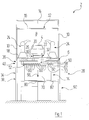
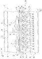
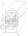
- FIGS. 1 to 3 show a system for coating objects with a coating booth 2.
- the coating booth 2 is formed as a spray booth in which vehicle bodies 4 are exposed to coating material in the form of paint.
- the coating booth 2 designed as a paint booth has a painting tunnel 8, which is delimited laterally by walls 10 and above a cabin ceiling 12.
- the paint tunnel 8 may be formed open at its end faces, not shown, or provided with at least one lock device.
- a lower opening 18 of the painting tunnel 8 is covered according to the examples shown by a grid 26, which may be formed preferably walkable.
- a steel structure 20 is provided on the lower opening 18 of the painting tunnel 8, above which a conveyor system 22 is arranged.
- vehicle bodies 4 to be painted can be conveyed from an input side of the painting tunnel 8 to an exit side of the painting tunnel 8.
- Fig. 2 shows an example according to which the vehicle bodies 4 be moved by means of the conveyor system 22 in the direction of arrow 98.
- FIGS. 1 to 3 Application examples shown, which are illustrated in the present case in the form of application robots 24 and by means of which the vehicle bodies 4 can be coated, for example with paint. Lacquer can be applied automatically by means of the application robot 24.
- the cabin ceiling 12 forms the lower boundary of an air supply space 14 and is designed as a filter cover 16.
- Air preferably conditioned air
- the painting tunnel 8 is arranged above a plant area 28 and open at the bottom in such a way that cabin exhaust air can flow downwards and can enter the plant area 28 as an exhaust air stream.
- the lower opening 18 of the painting tunnel is formed permeable to air, wherein a suitable cover of the opening 18 may be provided, for example, the grid 26 shown in the examples.
- the air absorbs particles, in particular overspray or overspray particles. With the exhaust air flow such particles are discharged from the paint tunnel 8.
- the cabin exhaust air laden with overspray from the paint booth as exhaust air flow down into the system area 28.
- the exhaust air flow led out of the coating booth 2 into the system area 28 firstly enters an inlet area 36.
- a charging area 40 is provided downstream of the inlet area 36 in the direction of flow.
- a separation region 34 is provided downstream of the separation region 34 in the flow direction.
- an outlet region 38 is provided downstream of the separation region 34 in the flow direction.
- the flow direction of the exhaust air flow is in Fig. 1 indicated by the arrow 96.
- the exhaust air flow is guided along the separation surfaces 70.
- particles can be deposited from the exhaust air stream of a deposition material such as water.
- suitable separation surfaces 70 of a separation device 74 are indicated, on which particles of the exhaust air can be deposited.
- separation surfaces 70 may be formed, for example, as lateral surfaces not shown Abscheideechen.
- the separation surfaces 70 may be provided, for example, on side plates of such separation units.
- wetting agents may be provided for the deposition surfaces 70, by means of which the separation surfaces 70 are wetted with a separating agent.
- one or more dispensers 72 may be associated with the deposition surfaces 70 (see FIG FIGS. 1 and 2 ) may be provided for discharging a separating liquid. In order to remove particles from the separation surfaces 70, the separation liquid may flow off the separation surfaces 70.
- deposition surfaces 70 may be formed of deposition material in a curtain-like manner, with the deposition material being discharged from a discharge channel 72 (see FIG FIGS. 1 and 2 ) is delivered.
- a discharge channel 72 can be provided with an exit slot, not shown, via which the deposition material can escape downwards.
- both liquids and solids or mixtures thereof can be used as the deposition material.
- a liquid deposition material such as water, or a mixture of liquid and solids is preferably and as in FIG. 2 indicated, creates a coherent liquid film.
- measures must be taken so that the Abscheide Jerusalem 70 can be acted upon by a largely continuous solid layer.
- a collection trough 82 For the removal of separated material from the separation region 34, a collection trough 82 (see FIGS. 1 and 3 ) be provided. Furthermore, suitable catching means 80 (see FIGS FIGS. 1 to 3 ) be provided for separation material or for Abscheideometechnik.
- the collecting means 80 may be formed, for example, as one or more collecting channels. Trapped separation material or trapped separation liquid as well as entrained deposited particles can be removed for example by means of the collecting channel 82.
- FIGS. 1 to 3 show a charging region 40 having an electrode assembly with one or more electrodes 60, 62 for forming an electrical charge enriched layer.
- the charging region 40 is formed spatially separated from the deposition region 34.
- the examples show that no electrodes 60, 62 are arranged between the deposition surfaces 70 of the deposition region 34.
- the electrodes 60, 62 are connected to one or more high voltage sources, these high voltage sources are not shown in detail in the drawings for the sake of clarity.
- the electrodes 60, 62 are preferably formed as negative Sprühelektroden.
- the electrodes 60, 62 connected to the pole of a high voltage source may have a high voltage in the range of about 20 kV to about 80 kV, e.g. about 45 kV.
- a corona cloud forms, in which particles are charged.
- a layer is produced by means of the electrodes 60, 62, in which the particles of the exhaust air flow are charged.
- the charging takes place for example by field charging or by diffusion charging, caused by the addition of negative charges when they collide with the particle.
- the charged particles leave the charging region 40 and migrate with the exhaust air flow into the separation region 34.
- the exhaust air stream entering the separation region 34 has previously flowed through the charge layer 40 enriched with electrical charges by means of the electrodes 60, 62. Charging of the particles in the exhaust air flow takes place according to the examples shown in the charging region 40 at least substantially before the particles reach the separation region 34.
- a ground potential is present, wherein preferably the deposition surfaces 70 are at ground potential. Charged particles release their charge in the deposition region 34 and are bound to the separation surfaces 70 by adhesive forces.
- the active elements in the charging region 40 and the passive elements in the deposition region 34 are arranged.
- the high voltage electrodes 60, 62 form the active elements
- the grounded deposition surfaces 70 form the passive elements.
- the electrodes 60, 62 are as in FIGS FIGS. 1 to 4 indicated in one or more electrode levels 50 and 52, respectively.
- the electrode planes 50, 52 are in Fig. 3 recognizable, for better clarity, however, not provided with reference numerals.
- the electrodes 60, 62 may be formed in the form of wires, for example.
- the electrodes 60, 62 preferably extend in at least one electrode plane 50, 52.
- the electrodes 60, 62 of an electrode plane 50, 52 may be arranged at equal distances from each other, for example.
- the direction in which the electrodes 60 are aligned in a first electrode plane 50 may differ from the direction in which the electrodes 62 are aligned in a first electrode plane 52. In this way, the electrodes 60, 62 can form a grid-shaped arrangement.
- the directions mentioned can be arranged for example at an angle of 90 ° to each other.
- Different electrode planes 50, 52 may be spaced apart from each other and / or overlapped, and may possibly touch each other. If the electrodes 60, 62 of different electrode planes 50 and 52 do not touch each other, they can be coupled to separate high voltage sources. Alternatively, a coupling with a common high voltage source can be provided.
- each section defined high voltage supply sections can, for example, along a paint tunnel be provided.
- Such subsections may be in a contact with a coating booth 2, for example along the direction of the material flow or the arrow 98 (see FIG. 2 ) can be arranged.
- the electrodes 60, 62 may be formed, for example, as at least substantially rectilinearly extending elements. Advantages of charging can be achieved when one or more electrodes 60, 62 have one or more tips. Preferably, such tips may at least partially protrude from an electrode plane 50, 52, wherein the tips may be formed, for example, mandrel-shaped. Such tips can also be formed, for example, by electrodes whose shape resembles a sawtooth. Another way of forming tips of an electrode 60, 62 is illustrated Fig. 4 in a highly schematic representation with reference to the electrode 60th
- Fig. 4 shows electrodes 60, 62 which extend substantially in two superimposed and spaced apart electrode planes 50 and 52, respectively.
- the tips of the electrode 60 which is arranged essentially in the upper plane 50, are aligned with the exhaust air stream, the exhaust air stream being in accordance with FIG Fig. 4 flows in the direction of arrow 94 through the charging region 40.
- the tips that are aligned with the exhaust air flow, ie in the direction of arrow 94.
- the exhaust air moves in the system area 28 from the inlet area 36 to the outlet area 38.
- air guiding devices can be provided.
- the FIGS. 1 and 3 show, for example, louvers that as down Converging air baffles 30, 32 are formed, for guiding the exhaust air flow in the direction of and through the plant area 28th
- One or more holding devices 58 may be provided for the electrodes.
- the at least one holding device 58 is preferably arranged at least substantially outside the exhaust air flow. Accordingly, the one or more holding devices 58 may be arranged, for example, covered by the air guide plates 30, 32.
- the holding devices 58 may preferably be designed in such a way that the electrodes 60, 62, which may be in the form of modules or modular units, may be easily removed, for example, for cleaning and preferably also easily reinserted. Expediently, the electrodes 60, 62 can be inserted or held in the at least one holding device 58 as grid-shaped modules.
- the plant area 28 may have a conditioning area 90 into which the exhaust air stream passes after leaving the exit area 38. If necessary, one or more filters are still present in the conditioning region 90 in order to remove, for example, possible residual particles or overspray residues or other impurities from the exhaust air flow.
- the cleaned cabin air can be at least partially conditioned so that it can be recirculated to the air supply chamber 14, from where it flows into the paint tunnel 8 again. Additionally or alternatively, outside air or fresh air can also be supplied to the air supply chamber 14.
- the present invention relates to a device for separating particles from an exhaust air flow, wherein the device has an inlet region 36 for the exhaust air flow, an outlet region 38 for the exhaust air flow, and one along the exhaust air flow arranged deposition device 74 and at least one electrode assembly, which electrode assembly is connected to a high voltage source, wherein a charging region 40 is provided, which has one or more electrodes 60, 62 for forming an electric charge-enriched layer, and wherein a Abscheide Jerusalem 70 having Abscheidegereich 34 is provided, which is arranged downstream of the charging area 40.
- the invention also relates to a method for separating particles from the exhaust air stream of a coating booth 2, wherein the exhaust air stream is first passed through a charging region 40 in which particles of the exhaust air are charged, and wherein the exhaust air stream leaves a deposition region 34 after leaving the charging region 40 flows through, in which charged particles of the exhaust air deposited on Abscheide Jerusalem 70.
- the advantages of the invention relate to improved commissioning, maintenance, cleaning or maintenance and a lower susceptibility to interference.
Landscapes
- Chemical & Material Sciences (AREA)
- Engineering & Computer Science (AREA)
- Analytical Chemistry (AREA)
- General Chemical & Material Sciences (AREA)
- Oil, Petroleum & Natural Gas (AREA)
- Chemical Kinetics & Catalysis (AREA)
- Electrostatic Separation (AREA)
- Details Or Accessories Of Spraying Plant Or Apparatus (AREA)
Applications Claiming Priority (1)
| Application Number | Priority Date | Filing Date | Title |
|---|---|---|---|
| DE102014018903.1A DE102014018903A1 (de) | 2014-12-17 | 2014-12-17 | Vorrichtung und Verfahren zum Abscheiden von Partikeln aus einem Abluftstrom einer Beschichtungskabine |
Publications (1)
| Publication Number | Publication Date |
|---|---|
| EP3034173A1 true EP3034173A1 (fr) | 2016-06-22 |
Family
ID=55027208
Family Applications (1)
| Application Number | Title | Priority Date | Filing Date |
|---|---|---|---|
| EP15003596.2A Withdrawn EP3034173A1 (fr) | 2014-12-17 | 2015-12-17 | Dispositif et procede de separation de particules d'un flux d'air provenant d'une cabine de peinture |
Country Status (4)
| Country | Link |
|---|---|
| US (1) | US10384213B2 (fr) |
| EP (1) | EP3034173A1 (fr) |
| CN (1) | CN105709980A (fr) |
| DE (1) | DE102014018903A1 (fr) |
Citations (9)
| Publication number | Priority date | Publication date | Assignee | Title |
|---|---|---|---|---|
| US3976031A (en) * | 1974-07-10 | 1976-08-24 | Onoda Cement Company, Ltd. | Electric discharge coating apparatus |
| US4643745A (en) * | 1983-12-20 | 1987-02-17 | Nippon Soken, Inc. | Air cleaner using ionic wind |
| WO1990007982A1 (fr) * | 1989-01-20 | 1990-07-26 | Fläkt Ab | Agencement servant a nettoyer de l'air de ventilation pollue par des particules de peinture |
| DE4139474A1 (de) * | 1990-11-30 | 1992-06-04 | Toshiba Kawasaki Kk | Elektro-staubabscheideanlage |
| US5264014A (en) * | 1989-04-25 | 1993-11-23 | Abb Flakt Aktiebolag | Arrangement for cleaning ventilation air polluted with paint particles |
| DE102008046414A1 (de) | 2008-09-04 | 2010-03-18 | Eisenmann Anlagenbau Gmbh & Co. Kg | Vorrichtung zum Abscheiden von Lack-Overspray |
| DE102010051086A1 (de) * | 2010-11-12 | 2012-05-16 | Eisenmann Ag | Verfahren zum elektrostatischen Beschichten von Gegenständen sowie Applikationsvorrichtung |
| DE102011109911A1 (de) * | 2011-08-10 | 2013-02-14 | Eisenmann Ag | Vorrichtung zum Abscheiden von Overspray |
| DE102012009723A1 (de) | 2012-05-16 | 2013-11-21 | Eisenmann Ag | Vorrichtung zum Abscheiden von Overspray sowie Anlage mit einer solchen |
Family Cites Families (18)
| Publication number | Priority date | Publication date | Assignee | Title |
|---|---|---|---|---|
| US4308038A (en) * | 1979-05-10 | 1981-12-29 | Santek, Inc. | Inertial-electrostatic wet precipitator |
| US4388089A (en) * | 1981-06-04 | 1983-06-14 | Santek, Inc. | Self-cleaning electro-inertial precipitator unit |
| US4529418A (en) * | 1982-01-15 | 1985-07-16 | Santek, Inc. | Inlet section for inertial-electrostatic precipitator unit |
| DE3215400A1 (de) * | 1982-04-24 | 1983-10-27 | Metallgesellschaft Ag | Nasselektrofilter fuer konverterabgase |
| AT377203B (de) * | 1982-06-17 | 1985-02-25 | Waagner Biro Ag | Filter zur elektrostatischen abscheidung von staeuben |
| DE8521209U1 (de) * | 1985-07-23 | 1986-02-27 | Christian, Franz, 4600 Dortmund | Elektrofilter |
| JPH0523614A (ja) * | 1991-07-17 | 1993-02-02 | Hitachi Plant Eng & Constr Co Ltd | 湿式電気集塵機 |
| US6238459B1 (en) * | 1999-04-23 | 2001-05-29 | The Babcock & Wilcox Company | Ultra-high particulate collection of sub-micron aerosols |
| WO2007056566A1 (fr) * | 2005-11-09 | 2007-05-18 | Sarnoff Corporation | Systeme et procede d'epuration d'air |
| JPWO2009104411A1 (ja) * | 2008-02-20 | 2011-06-23 | ダイキン工業株式会社 | 集塵装置 |
| DE102008046413B4 (de) * | 2008-09-04 | 2016-03-31 | Eisenmann Se | Vorrichtung zum Abscheiden von Lack-Overspray |
| DE102009006528A1 (de) * | 2009-01-28 | 2010-07-29 | Eisenmann Anlagenbau Gmbh & Co. Kg | Anlage zum Beschichten, insbesondere Lackieren, von Gegenständen, insbesondere Fahrzeugkarosserien |
| DE102009058206A1 (de) * | 2009-12-15 | 2011-06-16 | Eisenmann Anlagenbau Gmbh & Co. Kg | Verfahren und Vorrichtung zum Abscheiden von Overspray sowie Anlage mit einer solchen |
| DE102009058208A1 (de) | 2009-12-15 | 2011-06-16 | Eisenmann Anlagenbau Gmbh & Co. Kg | Verfahren und Vorrichtung zum Abscheiden von Overspray sowie Anlage mit einer solchen |
| DE102010007479B3 (de) * | 2010-02-09 | 2011-06-22 | EISENMANN Anlagenbau GmbH & Co. KG, 71032 | Anlage zum Beschichten von Gegenständen |
| ES2875054T3 (es) * | 2012-05-15 | 2021-11-08 | Univ Washington Through Its Center For Commercialization | Purificadores de aire electrónicos y sistemas y métodos asociados |
| US9308537B2 (en) * | 2012-12-26 | 2016-04-12 | Igor Krichtafovitch | Electrostatic air conditioner |
| KR101436293B1 (ko) * | 2013-01-07 | 2014-09-03 | 세이브기술 (주) | 습식 전기집진기용 수막형성장치 |
-
2014
- 2014-12-17 DE DE102014018903.1A patent/DE102014018903A1/de not_active Withdrawn
-
2015
- 2015-12-17 CN CN201511036115.7A patent/CN105709980A/zh active Pending
- 2015-12-17 US US14/972,437 patent/US10384213B2/en not_active Expired - Fee Related
- 2015-12-17 EP EP15003596.2A patent/EP3034173A1/fr not_active Withdrawn
Patent Citations (9)
| Publication number | Priority date | Publication date | Assignee | Title |
|---|---|---|---|---|
| US3976031A (en) * | 1974-07-10 | 1976-08-24 | Onoda Cement Company, Ltd. | Electric discharge coating apparatus |
| US4643745A (en) * | 1983-12-20 | 1987-02-17 | Nippon Soken, Inc. | Air cleaner using ionic wind |
| WO1990007982A1 (fr) * | 1989-01-20 | 1990-07-26 | Fläkt Ab | Agencement servant a nettoyer de l'air de ventilation pollue par des particules de peinture |
| US5264014A (en) * | 1989-04-25 | 1993-11-23 | Abb Flakt Aktiebolag | Arrangement for cleaning ventilation air polluted with paint particles |
| DE4139474A1 (de) * | 1990-11-30 | 1992-06-04 | Toshiba Kawasaki Kk | Elektro-staubabscheideanlage |
| DE102008046414A1 (de) | 2008-09-04 | 2010-03-18 | Eisenmann Anlagenbau Gmbh & Co. Kg | Vorrichtung zum Abscheiden von Lack-Overspray |
| DE102010051086A1 (de) * | 2010-11-12 | 2012-05-16 | Eisenmann Ag | Verfahren zum elektrostatischen Beschichten von Gegenständen sowie Applikationsvorrichtung |
| DE102011109911A1 (de) * | 2011-08-10 | 2013-02-14 | Eisenmann Ag | Vorrichtung zum Abscheiden von Overspray |
| DE102012009723A1 (de) | 2012-05-16 | 2013-11-21 | Eisenmann Ag | Vorrichtung zum Abscheiden von Overspray sowie Anlage mit einer solchen |
Also Published As
| Publication number | Publication date |
|---|---|
| US20160175873A1 (en) | 2016-06-23 |
| US10384213B2 (en) | 2019-08-20 |
| CN105709980A (zh) | 2016-06-29 |
| DE102014018903A1 (de) | 2016-06-23 |
Similar Documents
| Publication | Publication Date | Title |
|---|---|---|
| EP2258485B2 (fr) | Dispositif de séparation de pulvérisations de laque humide | |
| EP2822701B1 (fr) | Procédé et dispositif d'évacuation d'un air de traitement chargé d'un excès de peinture pulvérisée et installation de revêtement d'objets | |
| EP2773440B1 (fr) | Installation avec un dispositif servant à séparer un excédent de pulvérisation | |
| DE102008046413B4 (de) | Vorrichtung zum Abscheiden von Lack-Overspray | |
| DE102011108631A1 (de) | Verfahren und Vorrichtung zum Abscheiden von Overspray sowie Anlage mit einer solchen | |
| DE102013001982A1 (de) | Vorrichtung zum Abscheiden von Overspray | |
| EP2343130A1 (fr) | Dispositif de séparation du brouillard de peinture excédentaire | |
| EP2321066B1 (fr) | Dispositif de séparation d' excès de projection de peinture | |
| EP2452757B1 (fr) | Procédé et dispositif de séparation de pulvérisation ainsi qu'installation dotée de celui-ci | |
| EP2648855B1 (fr) | Installation pour la peinture d'objets | |
| EP3268109A1 (fr) | Dispositif de séparation pour la séparation de particules | |
| WO2013020641A1 (fr) | Dispositif de dépôt de l'excédent de peinture pulvérisée | |
| DE102009052655A1 (de) | Vorrichtung, System, Bauteil, Verfahren und Zusammensetzung zur Vermeidung von Ablagerungen eines Entsorgungsmittels in Beschichtungsanlagen | |
| DE102015016554A1 (de) | Vorrichtung zum Abscheiden von Overspray, Oberflächenbehandlungsanlage und Verfahren zum Abscheiden von Overspray | |
| EP3034173A1 (fr) | Dispositif et procede de separation de particules d'un flux d'air provenant d'une cabine de peinture | |
| EP2664388A2 (fr) | Dispositif de séparation de pulvérisation ainsi qu'installation dotée de celui-ci | |
| DE102008046410B4 (de) | Vorrichtung zum Abscheiden von Lack-Overspray | |
| EP3025785A2 (fr) | Dispositif et procédé de nettoyage de gaz de fumée d'une installation métallurgique | |
| DE102011012011A1 (de) | Vorrichtung zum Abscheiden von Overspray | |
| WO2014169992A1 (fr) | Dispositif de guidage d'air de traitement chargé d'un excès de peinture pulvérisée, et installation de revêtement présentant un tel dispositif | |
| DE102008011561A1 (de) | Einrichtung zur Reinigung ölhaltiger Abluft | |
| DE102011012013A1 (de) | Vorrichtung zum Abscheiden von Overspray | |
| DE102018133359A1 (de) | Anlage zur Beschichtung von Gegenständen | |
| AT514230B1 (de) | Rauchgasreinigungsanlage | |
| EP2382053A1 (fr) | Installation de revêtement, notamment de peinture, d'objets, notamment de carrosseries de véhicule |
Legal Events
| Date | Code | Title | Description |
|---|---|---|---|
| PUAI | Public reference made under article 153(3) epc to a published international application that has entered the european phase |
Free format text: ORIGINAL CODE: 0009012 |
|
| AK | Designated contracting states |
Kind code of ref document: A1 Designated state(s): AL AT BE BG CH CY CZ DE DK EE ES FI FR GB GR HR HU IE IS IT LI LT LU LV MC MK MT NL NO PL PT RO RS SE SI SK SM TR |
|
| AX | Request for extension of the european patent |
Extension state: BA ME |
|
| STAA | Information on the status of an ep patent application or granted ep patent |
Free format text: STATUS: REQUEST FOR EXAMINATION WAS MADE |
|
| 17P | Request for examination filed |
Effective date: 20161222 |
|
| RBV | Designated contracting states (corrected) |
Designated state(s): AL AT BE BG CH CY CZ DE DK EE ES FI FR GB GR HR HU IE IS IT LI LT LU LV MC MK MT NL NO PL PT RO RS SE SI SK SM TR |
|
| 19U | Interruption of proceedings before grant |
Effective date: 20190731 |
|
| 19W | Proceedings resumed before grant after interruption of proceedings |
Effective date: 20200803 |
|
| STAA | Information on the status of an ep patent application or granted ep patent |
Free format text: STATUS: EXAMINATION IS IN PROGRESS |
|
| 17Q | First examination report despatched |
Effective date: 20200903 |
|
| STAA | Information on the status of an ep patent application or granted ep patent |
Free format text: STATUS: THE APPLICATION IS DEEMED TO BE WITHDRAWN |
|
| 18D | Application deemed to be withdrawn |
Effective date: 20210114 |