EP3034237A1 - Ratschenschlüssel zur Verstärkung der Positionierungswirkung von Ratschen - Google Patents
Ratschenschlüssel zur Verstärkung der Positionierungswirkung von Ratschen Download PDFInfo
- Publication number
- EP3034237A1 EP3034237A1 EP14004290.4A EP14004290A EP3034237A1 EP 3034237 A1 EP3034237 A1 EP 3034237A1 EP 14004290 A EP14004290 A EP 14004290A EP 3034237 A1 EP3034237 A1 EP 3034237A1
- Authority
- EP
- European Patent Office
- Prior art keywords
- detent block
- ratchet
- detent
- trough
- control
- Prior art date
- Legal status (The legal status is an assumption and is not a legal conclusion. Google has not performed a legal analysis and makes no representation as to the accuracy of the status listed.)
- Withdrawn
Links
Images









Classifications
-
- B—PERFORMING OPERATIONS; TRANSPORTING
- B25—HAND TOOLS; PORTABLE POWER-DRIVEN TOOLS; MANIPULATORS
- B25B—TOOLS OR BENCH DEVICES NOT OTHERWISE PROVIDED FOR, FOR FASTENING, CONNECTING, DISENGAGING, OR HOLDING
- B25B13/00—Spanners; Wrenches
- B25B13/46—Spanners; Wrenches of the ratchet type, for providing a free return stroke of the handle
- B25B13/461—Spanners; Wrenches of the ratchet type, for providing a free return stroke of the handle with concentric driving and driven member
- B25B13/462—Spanners; Wrenches of the ratchet type, for providing a free return stroke of the handle with concentric driving and driven member the ratchet parts engaging in a direction radial to the tool operating axis
- B25B13/463—Spanners; Wrenches of the ratchet type, for providing a free return stroke of the handle with concentric driving and driven member the ratchet parts engaging in a direction radial to the tool operating axis a pawl engaging an externally toothed wheel
Definitions
- the present invention relates to a ratchet wrench structure, and more particularly to a ratchet wrench structure able to enhance the positioning effect of a ratchet.
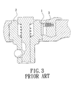
- a conventional ratchet wrench comprises a detent block 1 to lean against the inner wall of an accommodation trough 4, such that the detent block 1 and a ratchet ring 2 mesh with each other.
- the detent block 1 is biased by an elastic member 3 at one side only.
- the back of the detent block 1 is suspended in midair, without any support.
- the detent block 1 will use the support at one side thereof as a fulcrum to swing, and the teeth of the detent block 1, at the other end, will slightly disengage from the ratchet ring to bring a seesaw effect.
- the seesaw effect will make some teeth of the detent block be applied with the force to mesh the ratchet ring.
- the teeth of the detent block may burst into pieces, which will result in breakage of the ratchet wrench.
- a ratchet wrench having a dual rigid fulcrum is developed on the market, as shown in FIG. 2 .
- the detent block 1 of this ratchet wrench is biased by the elastic member 3, and the curved surface at one end of the detent block 1 leans against the inner wall of the accommodation trough 4.
- the other end of the detent block 1 is biased by a prop member 5 which holds against the top of a concave portion 6. Both ends of the detent block 1 are held by rigid fulcrums, respectively.
- the teeth of the detent block 1 are meshed with the teeth of the ratchet ring 2. The force applied to each tooth is even, so all the teeth are in an engagement state.
- This ratchet wrench doesn't have the problem that only some teeth are applied with the force.
- the number of the teeth to mesh with the ratchet ring is more than that of the conventional detent block and the engagement of the teeth is more stable, so the ratchet wrench can bear more torque value.
- the detent block 1 of this ratchet wrench is biased by the elastic member 3 for one end of the detent block 1 to lean against the inner wall of the accommodation trough 4, and the other end is held by the prop member 5 to form rigid fulcrums at the left and right ends of the detent block 1.
- the elastic member 3 only holds against the upper portion of the detent block 1, so the force applied to the upper and lower portions of the detent block 1 is not even.
- the lower portion of the detent block 1 without any support, may disengage from the ratchet ring 2.
- another conventional ratchet wrench uses the elastic member 3 to contact with the detent block 1, such that the detent block 1 is able to mesh with the outer periphery of the ratchet ring 2. Only one side of the detent block 1 is propped. The other side of the detent block 1 is suspended in midair, without any support. When the force applied to the detent block 1 reaches a certain value, the suspended side won't withstand the force so it will not generate any counterforce.
- the detent block 1 will use the support at one side thereof as a fulcrum to swing, and the teeth of the detent block 1, at the other end, will slightly disengage from the ratchet ring to bring a seesaw effect. The seesaw effect will make the force applied to the teeth of the detent block 1 uneven.
- the teeth of the detent block may burst into pieces, which will result in breakage of the ratchet wrench.
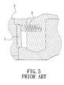
- the ratchet wrench comprises a control member 7.
- One side of the control member 7, facing the detent block 1, is formed with two limit grooves 8.
- Each limit groove 8 is provided with an elastic member 3.
- the limit groves 8 are arranged at the upper and lower portions of the control member 7, so that the elastic members 8 are to prop the upper and lower positions of the detent block 1, respectively. Therefore, the upper and lower portions of the detent block 1 mesh with the ratchet ring 2 at the same time.
- the elastic members 3 can overcome the obstruction, enabling the upper and lower portions of the detent block 1 to mesh with the ratchet ring 2 at the same time, avoiding the seesaw effect which causes a partial engagement.
- the primary objective of the present invention is to provide a ratchet wrench structure able to enhance the positioning effect of a ratchet.
- the ratchet wrench structure of the present invention can avoid the problem that a detent block and a ratchet ring are partially meshed with each other to result in breakage of teeth.
- the prevent invention can overcome the parallelism and perpendicularity tolerance problem that the conventional ratchet wrench uses a plurality of elastic positioning members to hold against the detent block, enhancing the positioning effect of the ratchet and stability of engagement.
- the ratchet wrench structure of the present invention comprises a wrench main body.
- the wrench main body has a handle.
- One end of the handle has a head portion.
- the head portion has an accommodation hole.
- the head portion is longitudinally formed with a control trough close to the handle.
- the head portion is transversely formed with a detent trough communicating with the control trough.
- a ratchet ring is pivotally disposed in the accommodation hole.
- the outer wall of the ratchet ring is formed with a plurality of drive teeth.
- the center of the ratchet ring is provided with an activating member.
- the activating member is adapted to turn a workpiece.
- a detent block is provided in the detent trough.
- a control device is provided in the control trough.
- the control device comprises a control member.
- One side of the control member, facing the detent trough is longitudinally formed with a rectangular limit groove.
- the rectangular limit groove is adapted to accommodate a rectangular spring.
- a prop pin is provided and biased by the rectangular spring.
- the prop pin has a rectangular slab shape corresponding to the rectangular limit groove. The prop pin longitudinally holds against the contact surface of the detent block.
- the control member is provided with a switch member, and the switch member is exposed out of the head portion.
- the ratchet wrench structure of the present invention is able to enhance the positioning effect of the ratchet.
- the prop pin longitudinally holds against the contact surface of the detent block to increase the area for applying the force.
- the detent block from top to bottom meshes with the ratchet ring. This won't have the problem of a partial engagement, increasing the stability of engagement and preventing the teeth from breaking.
- the prevent invention can overcome the parallelism and perpendicularity tolerance problem that the conventional ratchet wrench uses a plurality of elastic positioning members to hold against the detent block.
- the present invention discloses a ratchet wrench structure able to enhance the positioning effect of a ratchet.
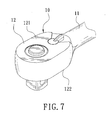
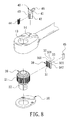
- the ratchet wrench structure comprises a wrench main body 10, a ratchet ring 20, a detent block 30, a control device 40, and a bottom lid 50.
- the wrench main body 10 has a handle 11. One end of the handle 11 has a head portion 12.
- the head portion 12 has a top 121 and a bottom 122.
- the head portion 12 has an accommodation hole 13 penetrating through the top 121 and the bottom 122.
- the accommodation hole 13 is substantially in the shape of a circle.
- the central axis of the accommodation hole 13 is perpendicular to the top 121 and the bottom 122.
- the top 121 of the head portion 12 has a control trough 14 close to the handle 11.
- the control trough 14 is substantially in the shape of a circle.
- the central axis of the control trough 14 is parallel to the central axis of the accommodation hole 13.
- the head portion 12 further has a detent trough 15 which is disposed in the accommodation hole 13 close to the handle 11 and communicates with the control trough 14.
- the detent trough 15 has a first holding surface 151 and an opposing second holding surface 152.
- the first holding surface 151 and the second holding surface 152 extend from the top 121 of the head portion 12 to the bottom 122 of the head portion 12.
- the detent trough 15 is gradually reduced from the accommodation hole 13 toward the control trough 14.
- the ratchet ring 20 is pivotally disposed in the accommodation hole 13 of the head portion 12.
- the outer wall of the ratchet ring 20 is formed with a plurality of drive teeth 21.
- the center of the ratchet ring 20 is provided with an activating member 22.
- the activating member 22 is adapted to turn a workpiece. In this present, the activating member 22 is a square protruding portion corresponding to a sleeve.
- the detent block 30 is disposed in the detent trough 15.
- the detent block 30 is selectively able to mesh with the ratchet ring 20.
- One side of the detent block 30, facing the accommodation hole 13, has a plurality of teeth 31 thereon.
- the teeth 31 are adapted to mesh with the drive teeth 21 of the ratchet ring 20.
- Another side of the detent block 30, facing the control trough 14, has a contact surface 32.
- the contact surface 32 has a concave curved shape.
- the middle portion of the contact surface 32 has a flange 33 corresponding to the central axis of the control trough 14. Through the flange 33, the contact surface 32 has a first contact surface 321 and a second contact surface 322 at two ends thereof.
- One end of the detent block 30, facing the first holding surface 151 has a first press surface 341, such that the first press surface 341 is selectively pressed against the first holding surface 151.
- Another end of the detent block 30, facing the second holding surface 152 has a second press surface 342, such that the second press surface 342 is selectively pressed against the second holding surface 152.
- the control device 40 is disposed in the control trough 14.
- the control device 40 is able to selectively control the engagement relationship between the detent block 30 and the ratchet ring 20.
- the control device 40 comprises a control member 41.
- the control member 41 is disposed in the control trough 14.
- the control member 41 has a connecting portion 42.
- the connecting portion 42 extends out of the control trough 14 to be exposed in the detent trough 15, enabling the control member 41 and the wrench main body 10 to bring a relative pivot relationship.
- One side of the connecting portion 42, facing the detent block 30, is longitudinally formed with a rectangular limit groove 43.
- the rectangular limit groove 43, corresponding to the detent block 30, is longitudinally disposed on the connecting portion 42 along the control trough 14.
- the rectangular limit groove 43 is to accommodate a rectangular spring 44.
- the rectangular spring 44 has a rectangular cross-section corresponding to the rectangular limit groove 43.
- a prop pin 45 is provided and biased by the rectangular spring 44.
- the prop pin 45 has a longitudinal length substantially corresponding to a longitudinal height of the detent block 30.
- the prop pin 45 has a rectangular slab shape corresponding to the rectangular limit groove 43.
- One end of the prop pin 45 is accommodated in the rectangular limit groove 43 to contact with the rectangular spring 44.
- Another end of the prop pin 45 extends out of the rectangular limit groove 43 to hold against the contact surface 32 of the detent block 30 along the central axis of the control trough 14.
- the end of the prop pin 45, corresponding to the contact surface 32 has a convex curved shape.
- the control member 41 is provided with a switch member 46 opposite the connecting portion 42. The switch member 46 is exposed out of the top 121 of the head portion 12.
- the bottom lid 50 is locked to the bottom 122 of the head portion 12 to surround the outer periphery of the ratchet ring 20, so that the ratchet ring 20 is confined in the accommodation hole 13 and the detent block 30 is confined in the detent trough 15.
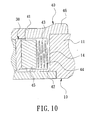
- the prop pin 45 of the ratchet wrench longitudinally holds against the contact surface 32 of the detent block 30, enabling the detent block 30 to mesh with the ratchet ring 20 and turn the ratchet ring 20 relative to the wrench main body 10.
- the first press surface 341 of the detent block 30 leans against the first contact surface 151.
- the first press surface 341 is tightly attached to the first contact surface 151 to form a large rigid support surface.
- the prop pin 45 longitudinally holds against the contact surface 32 of the detent block 30, enabling the prop pin 45 to hold against the detent block 30 by applying a force of large area.
- the prop pin 45 can hold against the upper, middle and lower positions of the detent block 30 at the same time, enabling the detent block 30 to tightly mesh with the ratchet ring 20 when the detent block 30 is moved.
- the force is applied to each tooth evenly and the engagement of each tooth is more stable, avoiding skid to cause that the applied force to the teeth is not even.
- the ratchet wrench not only enhances the positioning effect and stability of the ratchet but also bears a more torque value.
- the prop pin 45 is able to hold against the upper, middle and lower positions of the detent block 30 at the same time. If there is greasy dirt between the detent block 30 and the ratchet ring 20 when in use, the prop pin 45 which longitudinally holds against the detent block 30 can overcome the obstruction, enabling the upper, middle and lower positions of the detent block 30 to mesh with the ratchet ring 20 at the same time. This won't have the problem of a partial engagement.
- the detent block 30 and the ratchet ring 20 can mesh with each other at a high speed, increasing the stability of engagement and preventing the teeth from breaking.
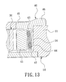
- the switch member 46 is switched for the prop pin 45 to be turned to hold against the second contact surface 322 of the detent block 30 from the first contact surface 321 of the detent block 30.
- the detent block 30 forms a rigid support surface on the second holding surface 152 for the user to operate the wrench main body 10 by changing a direction.
- the flange 33 provided between the first contact surface 321 and the second contact surface 322 of the detent block 30 forms a limit effect when the prop pin 45 holds against the detent block 30, such that the prop pin 45 precisely selects to hold against the first contact surface 321 or the second contact surface 322 to enhance the effect for the prop pin 45 to hold against the detent block 30, enabling the detent block 30 to mesh with the ratchet ring 20 better.
- the ratchet wrench uses the single prop pin 45 to longitudinally hold against the contact surface 32 of the detent block 30 for the detent block 30 from top to bottom to mesh with the ratchet ring 20.
- This can overcome the parallelism and perpendicularity tolerance problem that the conventional ratchet wrench uses a plurality of elastic positioning members to hold against the detent block.
- the present invention lowers the production cost and increases the production efficiency.
- the ratchet wrench structure of the present invention is able to enhance the positioning effect of the ratchet.
- the prop pin longitudinally holds against the contact surface of the detent block to increase the area for applying the force.
- the detent block from top to bottom meshes with the ratchet ring. This won't have the problem of a partial engagement, increasing the stability of engagement and preventing the teeth from breaking.
- the prevent invention can overcome the parallelism and perpendicularity tolerance problem that the conventional ratchet wrench uses a plurality of elastic positioning members to hold against the detent block.
Landscapes
- Engineering & Computer Science (AREA)
- Mechanical Engineering (AREA)
- Details Of Spanners, Wrenches, And Screw Drivers And Accessories (AREA)
Priority Applications (1)
| Application Number | Priority Date | Filing Date | Title |
|---|---|---|---|
| EP14004290.4A EP3034237A1 (de) | 2014-12-18 | 2014-12-18 | Ratschenschlüssel zur Verstärkung der Positionierungswirkung von Ratschen |
Applications Claiming Priority (1)
| Application Number | Priority Date | Filing Date | Title |
|---|---|---|---|
| EP14004290.4A EP3034237A1 (de) | 2014-12-18 | 2014-12-18 | Ratschenschlüssel zur Verstärkung der Positionierungswirkung von Ratschen |
Publications (1)
| Publication Number | Publication Date |
|---|---|
| EP3034237A1 true EP3034237A1 (de) | 2016-06-22 |
Family
ID=52146037
Family Applications (1)
| Application Number | Title | Priority Date | Filing Date |
|---|---|---|---|
| EP14004290.4A Withdrawn EP3034237A1 (de) | 2014-12-18 | 2014-12-18 | Ratschenschlüssel zur Verstärkung der Positionierungswirkung von Ratschen |
Country Status (1)
| Country | Link |
|---|---|
| EP (1) | EP3034237A1 (de) |
Citations (7)
| Publication number | Priority date | Publication date | Assignee | Title |
|---|---|---|---|---|
| US20030213342A1 (en) * | 2002-05-17 | 2003-11-20 | Arthur Wu | Ratchet wrench |
| US20050145075A1 (en) * | 2004-01-06 | 2005-07-07 | Lee Pei Y. | Reversible ratcheting tool with improved control member |
| US20050235783A1 (en) * | 2004-04-21 | 2005-10-27 | Stanley Chiro International, Ltd. | Ratchet wrench operated conveniently |
| US7114415B1 (en) * | 2005-10-14 | 2006-10-03 | William Tools Co., Ltd. | Control device for ratchet tool |
| CN201513495U (zh) * | 2009-10-28 | 2010-06-23 | 南车株洲电力机车有限公司 | 矩形弹簧 |
| EP2204264A1 (de) * | 2009-01-06 | 2010-07-07 | Bobby Hu | Ratschenschlüssel mit Verhinderung einer Verzahnungsgeschädigung |
| CN201896900U (zh) * | 2010-12-14 | 2011-07-13 | 宁波市海通汽车配件有限公司 | 一种长方形弹簧 |
-
2014
- 2014-12-18 EP EP14004290.4A patent/EP3034237A1/de not_active Withdrawn
Patent Citations (7)
| Publication number | Priority date | Publication date | Assignee | Title |
|---|---|---|---|---|
| US20030213342A1 (en) * | 2002-05-17 | 2003-11-20 | Arthur Wu | Ratchet wrench |
| US20050145075A1 (en) * | 2004-01-06 | 2005-07-07 | Lee Pei Y. | Reversible ratcheting tool with improved control member |
| US20050235783A1 (en) * | 2004-04-21 | 2005-10-27 | Stanley Chiro International, Ltd. | Ratchet wrench operated conveniently |
| US7114415B1 (en) * | 2005-10-14 | 2006-10-03 | William Tools Co., Ltd. | Control device for ratchet tool |
| EP2204264A1 (de) * | 2009-01-06 | 2010-07-07 | Bobby Hu | Ratschenschlüssel mit Verhinderung einer Verzahnungsgeschädigung |
| CN201513495U (zh) * | 2009-10-28 | 2010-06-23 | 南车株洲电力机车有限公司 | 矩形弹簧 |
| CN201896900U (zh) * | 2010-12-14 | 2011-07-13 | 宁波市海通汽车配件有限公司 | 一种长方形弹簧 |
Similar Documents
| Publication | Publication Date | Title |
|---|---|---|
| US20160167203A1 (en) | Ratchet wrench able to enhance positioning effect of ratchet | |
| US9114510B2 (en) | Pawl structure for ratchet wrenches and the wrenches using the same | |
| US20130074661A1 (en) | Tools with driving rods | |
| TW201634191A (zh) | 棘輪扳手方向切換構造 | |
| US10226861B2 (en) | Hand tool | |
| US20160375561A1 (en) | Ratchet wrench able to automatically adjust engaging tooth number according to extent of torsion | |
| TW201615353A (zh) | 可提升棘齒定位效果之棘輪扳手結構 | |
| US9884411B2 (en) | Tool structure | |
| US20170165814A1 (en) | Adjustable wrench | |
| US20160199966A1 (en) | Quick detachable wrench structure | |
| US8739659B2 (en) | Ratchet wrench | |
| CN106002792A (zh) | 一种扳手 | |
| CN105729358A (zh) | 可提升棘齿定位效果的棘轮扳手结构 | |
| JP5914627B1 (ja) | ラチェットレンチ | |
| KR101445676B1 (ko) | 맞춤 일체형 드라이버 | |
| JP5393430B2 (ja) | ソケットレンチ | |
| US20150082948A1 (en) | Ratcheting Tool | |
| US20170190040A1 (en) | Tool assembly | |
| CN203784072U (zh) | 防松螺纹组件 | |
| CN101985213A (zh) | 活动扳手 | |
| CN203622305U (zh) | 一种螺丝刀及其刀头 | |
| TWI412435B (zh) | 扳手 | |
| US8266987B1 (en) | Ratchet tool suitable for cooperating with thread forming taps | |
| US10016879B2 (en) | Adjustable wrench with reinforced structure | |
| TWM502545U (zh) | 棘輪接頭結構 |
Legal Events
| Date | Code | Title | Description |
|---|---|---|---|
| PUAI | Public reference made under article 153(3) epc to a published international application that has entered the european phase |
Free format text: ORIGINAL CODE: 0009012 |
|
| AK | Designated contracting states |
Kind code of ref document: A1 Designated state(s): AL AT BE BG CH CY CZ DE DK EE ES FI FR GB GR HR HU IE IS IT LI LT LU LV MC MK MT NL NO PL PT RO RS SE SI SK SM TR |
|
| AX | Request for extension of the european patent |
Extension state: BA ME |
|
| STAA | Information on the status of an ep patent application or granted ep patent |
Free format text: STATUS: THE APPLICATION HAS BEEN PUBLISHED |
|
| STAA | Information on the status of an ep patent application or granted ep patent |
Free format text: STATUS: THE APPLICATION IS DEEMED TO BE WITHDRAWN |
|
| 18D | Application deemed to be withdrawn |
Effective date: 20161223 |