EP3034254B1 - Bogenverarbeitungsvorrichtung - Google Patents
Bogenverarbeitungsvorrichtung Download PDFInfo
- Publication number
- EP3034254B1 EP3034254B1 EP15197799.8A EP15197799A EP3034254B1 EP 3034254 B1 EP3034254 B1 EP 3034254B1 EP 15197799 A EP15197799 A EP 15197799A EP 3034254 B1 EP3034254 B1 EP 3034254B1
- Authority
- EP
- European Patent Office
- Prior art keywords
- sheet
- conveying
- cutting
- pair
- conveying rollers
- Prior art date
- Legal status (The legal status is an assumption and is not a legal conclusion. Google has not performed a legal analysis and makes no representation as to the accuracy of the status listed.)
- Active
Links
Images












Classifications
-
- B—PERFORMING OPERATIONS; TRANSPORTING
- B65—CONVEYING; PACKING; STORING; HANDLING THIN OR FILAMENTARY MATERIAL
- B65H—HANDLING THIN OR FILAMENTARY MATERIAL, e.g. SHEETS, WEBS, CABLES
- B65H35/00—Delivering articles from cutting or line-perforating machines; Article or web delivery apparatus incorporating cutting or line-perforating devices, e.g. adhesive tape dispensers
- B65H35/0006—Article or web delivery apparatus incorporating cutting or line-perforating devices
-
- B—PERFORMING OPERATIONS; TRANSPORTING
- B26—HAND CUTTING TOOLS; CUTTING; SEVERING
- B26D—CUTTING; DETAILS COMMON TO MACHINES FOR PERFORATING, PUNCHING, CUTTING-OUT, STAMPING-OUT OR SEVERING
- B26D1/00—Cutting through work characterised by the nature or movement of the cutting member or particular materials not otherwise provided for; Apparatus or machines therefor; Cutting members therefor
- B26D1/01—Cutting through work characterised by the nature or movement of the cutting member or particular materials not otherwise provided for; Apparatus or machines therefor; Cutting members therefor involving a cutting member which does not travel with the work
- B26D1/04—Cutting through work characterised by the nature or movement of the cutting member or particular materials not otherwise provided for; Apparatus or machines therefor; Cutting members therefor involving a cutting member which does not travel with the work having a linearly-movable cutting member
- B26D1/06—Cutting through work characterised by the nature or movement of the cutting member or particular materials not otherwise provided for; Apparatus or machines therefor; Cutting members therefor involving a cutting member which does not travel with the work having a linearly-movable cutting member wherein the cutting member reciprocates
- B26D1/08—Cutting through work characterised by the nature or movement of the cutting member or particular materials not otherwise provided for; Apparatus or machines therefor; Cutting members therefor involving a cutting member which does not travel with the work having a linearly-movable cutting member wherein the cutting member reciprocates of the guillotine type
- B26D1/085—Cutting through work characterised by the nature or movement of the cutting member or particular materials not otherwise provided for; Apparatus or machines therefor; Cutting members therefor involving a cutting member which does not travel with the work having a linearly-movable cutting member wherein the cutting member reciprocates of the guillotine type for thin material, e.g. for sheets, strips or the like
-
- B—PERFORMING OPERATIONS; TRANSPORTING
- B23—MACHINE TOOLS; METAL-WORKING NOT OTHERWISE PROVIDED FOR
- B23Q—DETAILS, COMPONENTS, OR ACCESSORIES FOR MACHINE TOOLS, e.g. ARRANGEMENTS FOR COPYING OR CONTROLLING; MACHINE TOOLS IN GENERAL CHARACTERISED BY THE CONSTRUCTION OF PARTICULAR DETAILS OR COMPONENTS; COMBINATIONS OR ASSOCIATIONS OF METAL-WORKING MACHINES, NOT DIRECTED TO A PARTICULAR RESULT
- B23Q15/00—Automatic control or regulation of feed movement, cutting velocity or position of tool or work
-
- B—PERFORMING OPERATIONS; TRANSPORTING
- B26—HAND CUTTING TOOLS; CUTTING; SEVERING
- B26D—CUTTING; DETAILS COMMON TO MACHINES FOR PERFORATING, PUNCHING, CUTTING-OUT, STAMPING-OUT OR SEVERING
- B26D5/00—Arrangements for operating and controlling machines or devices for cutting, cutting-out, stamping-out, punching, perforating, or severing by means other than cutting
- B26D5/007—Control means comprising cameras, vision or image processing systems
-
- B—PERFORMING OPERATIONS; TRANSPORTING
- B26—HAND CUTTING TOOLS; CUTTING; SEVERING
- B26D—CUTTING; DETAILS COMMON TO MACHINES FOR PERFORATING, PUNCHING, CUTTING-OUT, STAMPING-OUT OR SEVERING
- B26D5/00—Arrangements for operating and controlling machines or devices for cutting, cutting-out, stamping-out, punching, perforating, or severing by means other than cutting
- B26D5/20—Arrangements for operating and controlling machines or devices for cutting, cutting-out, stamping-out, punching, perforating, or severing by means other than cutting with interrelated action between the cutting member and work feed
-
- B—PERFORMING OPERATIONS; TRANSPORTING
- B26—HAND CUTTING TOOLS; CUTTING; SEVERING
- B26D—CUTTING; DETAILS COMMON TO MACHINES FOR PERFORATING, PUNCHING, CUTTING-OUT, STAMPING-OUT OR SEVERING
- B26D1/00—Cutting through work characterised by the nature or movement of the cutting member or particular materials not otherwise provided for; Apparatus or machines therefor; Cutting members therefor
- B26D1/0006—Cutting members therefor
- B26D2001/0066—Cutting members therefor having shearing means, e.g. shearing blades, abutting blades
Definitions
- the present invention relates to a method for controlling a sheet processing apparatus. More specifically, the present invention relates to a method for controlling a sheet processing apparatus having a cutting mechanism which cuts a sheet in a direction orthogonal to a sheet conveying direction.
- a sheet processing apparatus which combines, as needed, a cutting mechanism, a slit forming mechanism which cuts a sheet in parallel with a sheet conveying direction, and a fold forming mechanism which forms a fold onto the sheet, by cassetting.
- FIG. 27 shows a cutting mechanism of a sheet processing apparatus.
- a cutting mechanism 201 includes an upper movable blade 201a, and a lower fixed blade 201b.
- the upper movable blade 201a is driven to be raised and lowered to cut sheet N at cutting position P1 in a direction orthogonal to sheet conveying direction F.
- a pair of conveying rollers 202 including an upper conveying roller 202a and a lower conveying roller 202b are arranged on the sheet conveying upstream side of the cutting mechanism 201.
- a pair of conveying rollers 203 including an upper conveying roller 203a and a lower conveying roller 203b are arranged on the sheet conveying downstream side of the cutting mechanism 201.
- a sheet receiving section 204 is arranged on the sheet conveying downstream side of the pair of conveying rollers 203 on the sheet conveying downstream side.
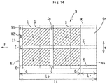
- Fig. 14 shows an example of the array pattern of products Q processed from one sheet N by the sheet processing apparatus.
- four products Q having folds are manufactured by a cutting process and a fold forming process.
- the slit forming mechanism cuts sheet N on a plurality of slitting lines E in parallel with sheet conveying direction F to cut away cut regions K at both ends and in the middle in sheet conveying width direction W
- the fold forming mechanism forms folds along folding lines G in sheet conveying width direction W orthogonal to sheet conveying direction F
- the cutting mechanism 201 ( Fig. 27 ) cuts sheet N on a plurality of cutting lines C and Cr in sheet conveying width direction W to cut front end cut region (front end margin) Sf, middle cut region Sm, and rear end cut region (rear end margin) Sr.
- Sheet conveying direction length Lr of rear end cut region Sr is different according to the size, number, and array of products Q.
- sheet conveying direction length Lr of rear end cut region Sr is too long, the cut strip in rear end cut region Sr after cutting cannot be discharged downward.
- the cut strip in rear end cut region Sr after cutting is vigorously fed out in conveying direction F by the pair of conveying rollers 202 on the conveying upstream side rotated at normal conveying speed V1.
- Predetermined fine-cutting unit length Lr0 is set to be the length to the extent that the cut strip in finely-cut divided region Sr0 can be discharged downward from a gap between the cutting mechanism 201 and the pair of conveying rollers 203 on the sheet conveying downstream side in Fig. 27 .
- Patent Document 1 Japanese Patent Laid-open Publication No. 2001-232700 , paragraph "0061", Fig. 8
- Figs. 30 to 35 show a cutting process for cutting and dividing rear end cut region Sr, as shown in Fig. 29 , in order.
- the rear end of rear end cut region Sr which is nipped between the pair of conveying rollers 202 on the sheet conveying upstream side is cut, and the cut strip in divided region Sr0 which has been cut into predetermined fine-cutting unit length Lr0 is then discharged downward from between the cutting mechanism 201 and the pair of conveying rollers 203 on the sheet conveying downstream side.
- rear end cut region Sr The cutting and dividing operation of rear end cut region Sr is advanced to shorten the remaining portion in rear end cut region Sr.
- rear edge Nb of rear end cut region Sr passes through nipping position P2 of the pair of conveying rollers 202 on the sheet conveying upstream side.
- rear edge Nb of the remaining portion in rear end cut region Sr is lifted by the reaction of the cutting operation.
- the remaining portion in rear end cut region Sr is retained by the lower fixed blade 201b and the lower conveying roller 202b on the sheet conveying upstream side to be stayed without being dropped.
- the pitch in the front-rear direction between the pair of conveying rollers 202 on the upstream side and the pair of conveying rollers 203 on the downstream side is narrowed.
- predetermined fine-cutting unit length Lr0 is required to be shorter.
- the sheet conveying distance for one fine-cutting and dividing operation becomes shorter, so that the rotational angle of the pair of conveying rollers 202 on the upstream side corresponding to the sheet conveying distance becomes smaller.
- An object of the present invention is to provide a method for controlling a sheet processing apparatus having a process for finely cutting, dividing, and discharging the rear end cut region of a sheet, in which a cut strip to be cut by a cutting mechanism and discharged downward can be immediately discharged downward without being stayed near the cutting mechanism.
- a method for controlling a sheet processing apparatus including a cutting mechanism which cuts a sheet in a direction orthogonal to a sheet conveying direction by a lower fixed blade and an upper movable blade, a pair of first conveying rollers which are arranged on the sheet conveying upstream side of the cutting mechanism and feed the sheet to the cutting mechanism, a pair of second conveying rollers which are arranged on the sheet conveying downstream side of the cutting mechanism, driving sources which independently drive the pair of first conveying rollers, the pair of second conveying rollers, and the cutting mechanism, and a control section which controls the operation of the driving sources, in which when sheet conveying direction length (Lr) of rear end cut region (Sr) of the sheet is equal to or more than predetermined value (Dn), rear end cut region (Sr) is sequentially cut and divided into predetermined fine-cutting unit length (Lr0) from the sheet conveying downstream end thereof, wherein when sheet conveying direction length (Lr) of rear end cut region (Sr) of the sheet is equal to or more than pre
- the first example preferably includes the following configuration.
- the sheet processing apparatus according to the first aspect may be as specified in claim 2.
- the sheet processing apparatus according to the first aspect may be as specified in claim 3.
- the sheet processing apparatus according to the first aspect may be as specified in claim 4
- the first aspect of the present invention is as follows:
- Fig. 1 is a schematic longitudinal sectional view of a sheet processing apparatus using a controlling method according to a first example which is not an embodiment of the present invention but which is helpful in understanding the present invention.
- the sheet processing apparatus includes a sheet receiving section 2 at the downstream end in sheet conveying direction F in an apparatus body 1, a sheet feeding section 3 at the upstream end in sheet conveying direction F therein, and a substantially horizontal conveying path 5 between the sheet feeding section 3 and the sheet receiving section 2.
- a suction conveying belt mechanism 8a and a feeding roller 8b are arranged in the sheet feeding section 3.
- a plurality of pairs of conveying rollers 9, 10, 11, 12, and 13 are spaced in sheet conveying direction F, and slit forming mechanisms 20, a fold forming mechanism 21, and a cutting mechanism 22 are arranged as processing mechanisms from the sheet conveying upstream side to the sheet conveying downstream side.
- a strip discharging section 23 is arranged at the lower end in the apparatus body 1, and accommodates a disposal strip after slitting and cutting.
- a reject mechanism 25 and a CCD sensor 26 are arranged on the sheet conveying upstream side of the slit forming mechanism 20.
- a cut strip dropping mechanism 27 is arranged on the sheet conveying downstream side of the slit forming mechanisms 20.
- the slit forming mechanisms 20, the fold forming mechanism 21, and the cutting mechanism 22 are removable units, and can be removably mounted in desired positions in the apparatus body 1 by cassetting. Therefore, according to process, the arranging order of the mechanisms 20, 21, and 22 can be changed, the mechanisms 20, 21, and 22 can be replaced with other mechanisms (a chamfering mechanism, and a perforation forming mechanism), and other mechanisms (a chamfering mechanism, and a perforation forming mechanism) can be added.
- the pairs of conveying rollers 9, 10, 11, 12, and 13 are connected to roller driving sources 41, 42, 43, and 44, respectively, via a power transmission mechanism.
- the roller driving sources 41, 42, 43, and 44 are electrically connected to a control section 45.
- the control section 45 incorporates a CPU, and a memory device, such as a RAM and a ROM.
- An operation panel 46 and the CCD sensor 26 are electrically connected to the interface of the control section 45 to input and display operation settings information.
- a plurality of optically transmission type sheet detection sensors 31, 32, 33, 34, and 35 are arranged on the conveying path 5, detect front edge (sheet conveying downstream edge) Na or rear edge (sheet conveying upstream edge) Nb of sheet N, and are electrically connected to the interface of the control section 45.
- the first sheet detection sensor 31 on the extreme sheet conveying upstream side of the conveying path 5 is arranged near the sheet conveying upstream side of the CCD sensor 26.
- the second sheet detection sensor 32 is arranged near the sheet conveying upstream side of the slit forming mechanisms 20.
- the third sheet detection sensor 33 is arranged midway in the slit forming mechanisms 20.
- the fourth sheet detection sensor 34 is arranged near the sheet conveying upstream side of the fold forming mechanism 21.
- the fifth sheet detection sensor 35 on the extreme sheet conveying downstream side of the conveying path 5 is arranged near the sheet conveying upstream side of the sheet receiving section 2.
- the first sheet detection sensor 31 on the extreme conveying direction upstream side of the conveying path 5 detects front edge Na or rear edge Nb of sheet N fed from the sheet feeding section 3 and nipped between the pair of conveying rollers 9, and uniquely detects the position of sheet N conveyed on the conveying path 5 with reference to the detected sheet position.
- the second sheet detection sensor 32 and the third sheet detection sensor 33 detect jamming of sheet N.
- the fourth sheet detection sensor 34 is auxiliary provided to correct sheet position information obtained from the first sheet detection sensor 31 more precisely when the conveying path 5 becomes long to cause accumulation of shifts (conveying errors) in sheet conveying direction F of sheet N on the conveying path 5.
- the fifth sheet detection sensor 35 detects conveying-out of product Q into the sheet receiving section 2 and jamming.
- the first example relates to the control of the cutting mechanism 22 and the pairs of conveying rollers 12 and 13 therenear of the sheet processing apparatus, and other processing mechanisms and sections will be briefly described.
- the sheet feeding section 3 incorporates a suction conveying belt mechanism, and feeds a predetermined number of sheets N stacked on a sheet tray 3a one by one from the uppermost sheet onto the conveying path 5 by the suction conveying belt mechanism 8a and the feeding roller 8b.
- the feeding roller 8 and the suction conveying belt mechanism are connected to a sheet-feeding driving source 47 which is electrically connected to the control section 45.
- the CCD sensor 26 can automatically read the operation settings information. Specifically, the CCD sensor 26 reads the image of position mark M1 printed at the front end corner of sheet N, as shown in Fig. 14 , to detect the reference positions of the processes in sheet conveying direction F of sheet N and in sheet conveying width direction W orthogonal to the sheet conveying direction, and reads the image of barcode M2 printed at the front end of sheet N to obtain the operation settings information to be provided to sheet N.
- the operation settings information includes, for instance, entire length La in sheet conveying direction F and the entire width of sheet N, and the positions of cutting lines C, C, Cr, and E and folding line G according to the size, number, and arrangement of products Q to be processed.
- Length Lb in Fig. 14 denotes the length from front edge Na of sheet N to cutting line Cr at the conveying downstream end of rear end cut region Sr.
- the reject mechanism 25 in Fig. 1 is operated with respect to unreadable sheet N to drop sheet N so that a disposal sheet tray 25a collects sheet N.
- each of the slit forming mechanisms 20 includes two pairs of rotational blades 36, each pair including upper and lower rotational blades spaced in conveying width direction W.
- the lower rotational blade is connected to a rotational blade driving source 48, such as a motor, via a power transmission mechanism. That is, the lower rotational blade is rotated by the driving force of the rotational blade driving source 48 to form a slit with respect to sheet N in parallel with sheet conveying direction F.
- the interval in conveying width direction W between the pairs of rotational blades 36 can be optionally changed.
- the cut strip dropping mechanism 27 discharges a cut strip caused by cutting of the slit forming mechanism 20 (cut region K in Fig. 14 ) to the outside of the conveying path 5, and drops the cut strip into the strip discharging section 23 when sheet N passes through the cut strip dropping mechanism 27.
- the fold forming mechanism 21 includes a lower die 21B having an upper end concave portion, and an upper die 21A having a lower end convex portion fitted into the concave portion.
- the upper die 21A is connected to a die driving source 49, such as a motor, via a power transmission mechanism. That is, the upper die 21A is moved down by the driving force of the die driving source 49 to form a fold with respect to sheet N in sheet conveying width direction W orthogonal to sheet conveying direction F.
- the cutting mechanism 22 includes a lower fixed blade 22B and an upper movable blade 22A, which extend in sheet conveying width direction W.
- the upper movable blade 22A is connected to a cutting driving source 50, such as a motor, via a power transmission mechanism.
- a cutting driving source 50 such as a motor
- the pair of conveying rollers 12 on the sheet conveying upstream side of the cutting mechanism 22 are referred to as a pair of first conveying rollers
- the pair of conveying rollers 13 on the sheet conveying downstream side of the cutting mechanism 22 are referred to as a pair of second conveying rollers.
- the pair of first conveying rollers 12 and the pair of second conveying rollers 13 include lower conveying rollers 12B and 13B on the driving side, which are connected to the roller driving sources 43 and 44, respectively and upper conveying rollers 12A and 13A on the driven side.
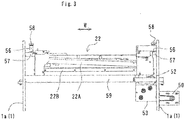
- Fig. 2 is a specific example of the cutting mechanism 22.
- the lower fixed blade 22B is substantially horizontally arranged to extend in sheet conveying width direction W.
- the upper movable blade 22A is tilted with respect to a horizontal direction to be lowered from a blade distal portion 22Aa to a blade base portion 22Ab, and is moved in an up-down direction along an upper guide body 29 arranged on the upstream side in sheet conveying direction F.
- the blade base portion 22Ab of the upper movable blade 22A is engaged with the cutting driving source (driving motor) 50 via a parallel link mechanism 51, a crank mechanism 52, and a gear transmission mechanism 53.
- the cutting driving source 50 driving motor
- the upper movable blade 22A in tilted state is moved in parallel with the up-down direction.
- the cutting mechanism 22 includes mounting members 56 at both upper ends thereof in sheet conveying width direction W. These mounting members 56 are fixed to support bases 57 provided at the upper ends of a pair of vertical walls 1a of the apparatus body 1 with bolt units 58. In addition, the lower end of the cutting mechanism 22 is placed on a cross member 59 extended between the vertical walls 1a.
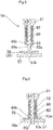
- each of the bolt units 58 includes a bolt shaft 60, a bolt head 61 fixed onto the upper end of the bolt shaft 60, a retaining ring 63 fitted to the bolt shaft 60 to be axially movable, and a coil spring 62 contracted between the retaining ring 63 and the bolt head 61.
- a male screw 60a is formed at the lower end of the bolt shaft 60.
- a brim 60b is integrally formed at the upper end of the male screw 60a.
- the retaining ring 63 is formed with a concave portion 63a in the lower surface thereof. The concave portion 63a accommodates the brim 60b of the bolt shaft 60.
- the coil spring 62 urges the retaining ring 63 downward to press the retaining ring 63 onto the upper surface of the brim 60b.
- each of the mounting members 56 of the cutting mechanism 22 is placed on each of the support bases 57 of the apparatus body 1, so that the male screw 60a at the lower end of the bolt shaft 60 is inserted through a bolt insertion hole 56a in the mounting member 56 and as shown in Fig. 6 , is screwed into a female screw hole 57a in the support base 57.
- the male screw 60a is screwed into the female screw hole 57a, then, the lower end of the retaining ring 63 is abutted onto the mounting member 56 to screw the male screw 60a further into the female screw hole 57a, so that the retaining ring 63 compresses the coil spring 62.
- the resilient force of the compressed coil spring 62 urges the bolt shaft 60 upward via the bolt head 61 to abut the tooth surface of the male screw 60a onto the tooth surface of the female screw hole 57a. With this, the bolt unit 58 cannot be loosened by severe vibration.
- a program including the following steps for the cutting process is incorporated into the control section 45 in Fig. 1 .
- Fig. 13 is a time chart of operations of the pair of first conveying rollers 12, the pair of second conveying rollers 13, and the cutting mechanism 22 in the third step.
- T0 indicates time from start of cutting (Cr) of rear end cut region Sr to completion of discharge of rearmost end divided region Sr1.
- T1, T2, and T3 indicate cutting operation time on cutting lines Cr, Cr0, and Cr1 for division.
- T4 and T5 indicate conveying time of the pair of first conveying rollers 12 at normal conveying speed V1 after cutting on cutting lines Cr and Cr0.
- T6 indicates operation time during which the cut strip in rearmost end divided region Sr1 is discharged by the pair of first conveying rollers 12 at limited conveying speed V2 after cutting on second cutting line Cr1 for division.
- a sheet processing apparatus used in the embodiment of the first aspect of the present invention is the same as the sheet processing apparatus used in the first example described with reference to Figs. 1 to 6 except for the control contents of the control section 45 for the cutting mechanism 22.
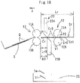
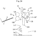
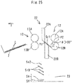
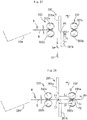
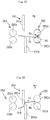
- dimension signs D4 and D5 are shown in the cutting mechanism 22 in Fig. 16 . That is, as described above, dimension sign D1 denotes the distance between cutting position P1 and nipping position P2 of the pair of first conveying rollers 12 (the minimum reference length), D2 denotes the maximum reference length ( Fig. 7 ), and D3 denotes the interval between the cutting mechanism 22 (the lower fixed blade 22B) and the pair of second conveying rollers 13.
- D4 denotes the interval between the cutting mechanism 22 (the lower fixed blade 22B) and the pair of first conveying rollers 12
- D5 denotes the diameter of the lower conveying roller 12B of the pair of first conveying rollers 12.
- a program including the following steps for the cutting process is incorporated into the control section 45 in Fig. 1 .
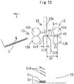
- the pair of first conveying rollers 12 feed sheet N into the cutting mechanism 22 in Fig. 1 at normal conveying speed V1, and the cutting mechanisms 22 cuts sheet N on cutting lines C and Cr in Fig. 14 .
- the cut strips in front end cut region Sf and middle cut region Sm after cutting pass through between the cutting mechanism 22 and the pair of second conveying rollers 13 to be discharged downward into the strip discharging section 23.
- the cut strip in rear end cut region Sr is discharged by the following different method according to the value of sheet conveying direction length Lr.
- sheet conveying direction length Lr of rear end cut region Sr is equal to or more than predetermined value Dn.
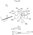
- rear end cut region Sr is cut into divided region Sr0 having predetermined fine-cutting unit length Lr0 sequentially from the sheet conveying direction downstream end thereof.
- Cut strip (Sr0) is discharged from between the cutting mechanism 22 and the pair of second conveying rollers 13 downward into the strip discharging section 23.
- the conveying speed of the pair of first conveying rollers 12 is normal conveying speed V1.
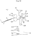
- the cut strip is started to be dropped from the pair of first conveying rollers 12.
- the cutting mechanism 22 performs the re-cutting operation to give an impact to near the front end of the cut strip in rearmost end divided region Sr1.
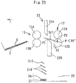
- the cut strip in rearmost end divided region Sr1 passes through between the cutting mechanism 22 and the pair of first conveying rollers 12 to be immediately discharged downward into the strip discharging section 23.
- the pair of first conveying rollers 12 are held rotated to continue conveying.
Landscapes
- Engineering & Computer Science (AREA)
- Mechanical Engineering (AREA)
- Life Sciences & Earth Sciences (AREA)
- Forests & Forestry (AREA)
- Computer Vision & Pattern Recognition (AREA)
- Details Of Cutting Devices (AREA)
Claims (4)
- Bogenverarbeitungsvorrichtung, umfassend:einen Schneidemechanismus (22), wobei der Schneidemechanismus (22) so konfiguriert ist, dass er einen Bogen in einer Richtung rechtwinkelig zu einer Bogenförderrichtung durch eine obere und eine untere Schneidklinge (22A, 22B) an den gegenüberliegenden Seiten einer Bogenförderfläche schneidet,ein Paar von ersten Förderwalzen (12), die auf der in Bezug auf die Bogenförderung stromauf liegenden Seite des Schneidemechanismus (22) angeordnet sind und so konfiguriert sind, dass sie dem Schneidemechanismus (22) den Bogen zuführen,ein Paar von zweiten Förderwalzen (13), die auf der in Bezug auf die Bogenförderung stromab liegenden Seite des Schneidemechanismus (22) angeordnet sind,dadurch gekennzeichnet, dass die Bogenverarbeitungsvorrichtung Folgendes umfasst:Antriebsquellen (43, 44, 50), die so konfiguriert sind, dass sie das Paar von ersten Förderwalzen (12), das Paar von zweiten Förderwalzen (13) und den Schneidemechanismus (22) unabhängig voneinander antreiben,und einen Steuerabschnitt (45), der so konfiguriert ist, dass er den Betrieb der Antriebsquelle (43, 44, 50) steuert, wobei, wenn eine Bogenförderrichtungslänge (Lr) eines hinteren Endschnittbereichs (Sr) des Bogens gleich oder höher als ein vorgegebener Wert (Dn) ist, der hintere Endschnittbereich (Sr) nacheinander geschnitten und in eine vorbestimmte Feinschneideeinheitslänge (Lr0) von dem stromab desselben liegenden Bogenförderende geteilt wird,wobei der Steuerabschnitt (45) so konfiguriert ist, dass er die Antriebsquellen (43, 44, 50) so steuert, dass die Bogenförderrichtungslänge (Lr1) des am hintersten Ende geteilten Bereichs (Sr1) im hinteren Endschnittbereich (Sr) die Länge ist, die im Wesentlichen dem Abstand (D1) zwischen einer Schneideposition (P1) des Schneidemechanismus (22) und einer Klemmposition (P2) des Paars von ersten Förderwalzen (12) entspricht, und dass, wenn der am hintersten Ende geteilte Bereich (Sr1) durch die Klemmposition (P2) des Paars von ersten Förderwalzen (12) hindurchtritt, das Paar von ersten Förderwalzen (12) um 90° oder mehr gedreht wird.
- Vorrichtung nach Anspruch 1, wobei, nachdem das Paar von ersten Förderwalzen (12) um 90° oder mehr gedreht worden ist, der Schneidemechanismus (22) so gesteuert wird, dass er einen Nachschneidevorgang in Bezug auf den am hintersten Ende geteilten Bereich (Sr1) durchführt.
- Vorrichtung nach Anspruch 2, wobei das Paar von ersten Förderwalzen (12) zum Zeitpunkt des Nachschneidevorgangs des Schneidemechanismus (22) angehalten werden.
- Vorrichtung nach Anspruch 3, wobei das Paar von ersten Förderwalzen (12) so gesteuert wird, dass die Drehung nach dem Nachschneidevorgang des Schneidemechanismus (22) wieder aufgenommen wird.
Applications Claiming Priority (4)
| Application Number | Priority Date | Filing Date | Title |
|---|---|---|---|
| JP2011066294A JP5698048B2 (ja) | 2011-03-24 | 2011-03-24 | 用紙加工装置の制御方法 |
| JP2011222717A JP5814067B2 (ja) | 2011-10-07 | 2011-10-07 | 用紙加工装置の制御方法 |
| EP12761209.1A EP2689902B1 (de) | 2011-03-24 | 2012-02-15 | Blattverarbeitungsvorrichtung |
| PCT/JP2012/053461 WO2012127940A1 (ja) | 2011-03-24 | 2012-02-15 | 用紙加工装置の制御方法 |
Related Parent Applications (2)
| Application Number | Title | Priority Date | Filing Date |
|---|---|---|---|
| EP12761209.1A Division-Into EP2689902B1 (de) | 2011-03-24 | 2012-02-15 | Blattverarbeitungsvorrichtung |
| EP12761209.1A Division EP2689902B1 (de) | 2011-03-24 | 2012-02-15 | Blattverarbeitungsvorrichtung |
Publications (2)
| Publication Number | Publication Date |
|---|---|
| EP3034254A1 EP3034254A1 (de) | 2016-06-22 |
| EP3034254B1 true EP3034254B1 (de) | 2020-09-09 |
Family
ID=46879104
Family Applications (2)
| Application Number | Title | Priority Date | Filing Date |
|---|---|---|---|
| EP15197799.8A Active EP3034254B1 (de) | 2011-03-24 | 2012-02-15 | Bogenverarbeitungsvorrichtung |
| EP12761209.1A Not-in-force EP2689902B1 (de) | 2011-03-24 | 2012-02-15 | Blattverarbeitungsvorrichtung |
Family Applications After (1)
| Application Number | Title | Priority Date | Filing Date |
|---|---|---|---|
| EP12761209.1A Not-in-force EP2689902B1 (de) | 2011-03-24 | 2012-02-15 | Blattverarbeitungsvorrichtung |
Country Status (3)
| Country | Link |
|---|---|
| US (1) | US9061856B2 (de) |
| EP (2) | EP3034254B1 (de) |
| WO (1) | WO2012127940A1 (de) |
Families Citing this family (8)
| Publication number | Priority date | Publication date | Assignee | Title |
|---|---|---|---|---|
| CN104150265B (zh) * | 2014-07-31 | 2016-08-17 | 江苏申凯包装高新技术股份有限公司 | 一种分切机用接料盘组件 |
| CN104960019B (zh) * | 2015-06-03 | 2017-03-01 | 合肥鑫晟光电科技有限公司 | 异方向性导电胶膜切割校准系统和方法 |
| EP3326945B1 (de) * | 2015-07-23 | 2020-03-18 | Horizon International Inc. | Bogenschneidvorrichtung |
| CN108584519A (zh) * | 2017-12-15 | 2018-09-28 | 饭田(佛山)橡塑有限公司 | 一种片材产品分切机 |
| JP7380207B2 (ja) * | 2019-12-26 | 2023-11-15 | セイコーエプソン株式会社 | 印刷装置、搬送制御方法 |
| JP7404900B2 (ja) * | 2020-01-31 | 2023-12-26 | セイコーエプソン株式会社 | 印刷装置 |
| JP7565581B2 (ja) * | 2020-09-25 | 2024-10-11 | 株式会社Isowa | 段ボールシート製函機 |
| CN114290390A (zh) * | 2021-12-29 | 2022-04-08 | 启东市美迅机械有限公司 | 一种高精度芯板横切机构 |
Family Cites Families (8)
| Publication number | Priority date | Publication date | Assignee | Title |
|---|---|---|---|---|
| DE3329987C1 (de) * | 1983-08-19 | 1984-12-13 | Jagenberg AG, 4000 Düsseldorf | Vorrichtung zum Einfuehren einer Warenbahn in eine Behandlungsmaschine |
| JP4762394B2 (ja) | 2000-02-22 | 2011-08-31 | デュプロ精工株式会社 | 用紙裁断装置 |
| EP1719726B1 (de) * | 2004-02-24 | 2013-09-25 | Duplo Seiko Corporation | Papierbogenverarbeitungsvorrichtung |
| DE102008006562A1 (de) * | 2008-01-29 | 2009-10-15 | Böwe Systec AG | Verfahren und Vorrichtung zum Transport von Papier in einer Papierhandhabungsanlage von einem ersten Transport an einen zweiten Transport |
| JP2010240820A (ja) * | 2009-04-07 | 2010-10-28 | Gansaa Japan Kk | 余白断裁片の排出機構および掃き落とし機構を備えた枚葉紙搬送断裁装置 |
| JP2010274353A (ja) * | 2009-05-27 | 2010-12-09 | Noritsu Koki Co Ltd | プリント処理装置 |
| JP4964978B2 (ja) * | 2009-09-08 | 2012-07-04 | 東芝テック株式会社 | 媒体検出方法、媒体検出装置、媒体排出装置、及び印刷装置 |
| US8316749B2 (en) * | 2010-05-13 | 2012-11-27 | Eastman Kodak Company | Finisher for cutting or scoring receiver |
-
2012
- 2012-02-15 EP EP15197799.8A patent/EP3034254B1/de active Active
- 2012-02-15 WO PCT/JP2012/053461 patent/WO2012127940A1/ja not_active Ceased
- 2012-02-15 US US14/005,901 patent/US9061856B2/en active Active
- 2012-02-15 EP EP12761209.1A patent/EP2689902B1/de not_active Not-in-force
Non-Patent Citations (1)
| Title |
|---|
| None * |
Also Published As
| Publication number | Publication date |
|---|---|
| EP2689902A4 (de) | 2015-10-14 |
| US20140011654A1 (en) | 2014-01-09 |
| EP2689902B1 (de) | 2016-12-14 |
| US9061856B2 (en) | 2015-06-23 |
| WO2012127940A1 (ja) | 2012-09-27 |
| EP3034254A1 (de) | 2016-06-22 |
| EP2689902A1 (de) | 2014-01-29 |
Similar Documents
| Publication | Publication Date | Title |
|---|---|---|
| EP2689902B1 (de) | Blattverarbeitungsvorrichtung | |
| JP5517690B2 (ja) | 用紙加工装置 | |
| JP5773511B2 (ja) | 打抜き機 | |
| US9944039B2 (en) | Corrugated paperboard sheet manufacturing apparatus | |
| JP5698048B2 (ja) | 用紙加工装置の制御方法 | |
| EP1719726B1 (de) | Papierbogenverarbeitungsvorrichtung | |
| JP2001232700A (ja) | 用紙裁断装置および折り型形成装置 | |
| US10189668B2 (en) | Sheet cutting machine | |
| EP2471732B1 (de) | Papierfaltvorrichtung | |
| EP3299321B1 (de) | Verarbeitungsvorrichtung umfassend eine staplervorrichtung | |
| JP7160259B2 (ja) | 用紙加工装置 | |
| JP6370053B2 (ja) | 用紙加工装置 | |
| JP6982283B2 (ja) | 加工処理装置 | |
| JP2007030178A (ja) | 段ボールシートの製造装置 | |
| JP6786032B2 (ja) | 加工処理装置及びシートの加工処理方法 | |
| US12459149B2 (en) | Apparatus for processing sheets | |
| JP4463086B2 (ja) | シートスタッカ | |
| WO2024203447A1 (ja) | 缶製品作製装置、検査方法、および検査プログラム | |
| JP7040764B2 (ja) | シート加工装置 | |
| JP2019034822A (ja) | 加工装置 | |
| JP2012183729A (ja) | 画像記録装置及びその制御方法 | |
| HK1098444A (en) | Paper sheet processing device |
Legal Events
| Date | Code | Title | Description |
|---|---|---|---|
| PUAI | Public reference made under article 153(3) epc to a published international application that has entered the european phase |
Free format text: ORIGINAL CODE: 0009012 |
|
| AC | Divisional application: reference to earlier application |
Ref document number: 2689902 Country of ref document: EP Kind code of ref document: P |
|
| AK | Designated contracting states |
Kind code of ref document: A1 Designated state(s): AL AT BE BG CH CY CZ DE DK EE ES FI FR GB GR HR HU IE IS IT LI LT LU LV MC MK MT NL NO PL PT RO RS SE SI SK SM TR |
|
| 17P | Request for examination filed |
Effective date: 20160719 |
|
| RBV | Designated contracting states (corrected) |
Designated state(s): AL AT BE BG CH CY CZ DE DK EE ES FI FR GB GR HR HU IE IS IT LI LT LU LV MC MK MT NL NO PL PT RO RS SE SI SK SM TR |
|
| GRAP | Despatch of communication of intention to grant a patent |
Free format text: ORIGINAL CODE: EPIDOSNIGR1 |
|
| STAA | Information on the status of an ep patent application or granted ep patent |
Free format text: STATUS: GRANT OF PATENT IS INTENDED |
|
| INTG | Intention to grant announced |
Effective date: 20200323 |
|
| GRAS | Grant fee paid |
Free format text: ORIGINAL CODE: EPIDOSNIGR3 |
|
| GRAA | (expected) grant |
Free format text: ORIGINAL CODE: 0009210 |
|
| STAA | Information on the status of an ep patent application or granted ep patent |
Free format text: STATUS: THE PATENT HAS BEEN GRANTED |
|
| RIN1 | Information on inventor provided before grant (corrected) |
Inventor name: OTA, SATOSHI Inventor name: KOSAKA, SHUHEI Inventor name: MAEDA, TAKAAKI Inventor name: FUNASE, MASASUKE Inventor name: TOKI, AKIHIKO |
|
| AC | Divisional application: reference to earlier application |
Ref document number: 2689902 Country of ref document: EP Kind code of ref document: P |
|
| AK | Designated contracting states |
Kind code of ref document: B1 Designated state(s): AL AT BE BG CH CY CZ DE DK EE ES FI FR GB GR HR HU IE IS IT LI LT LU LV MC MK MT NL NO PL PT RO RS SE SI SK SM TR |
|
| REG | Reference to a national code |
Ref country code: GB Ref legal event code: FG4D |
|
| REG | Reference to a national code |
Ref country code: AT Ref legal event code: REF Ref document number: 1311008 Country of ref document: AT Kind code of ref document: T Effective date: 20200915 Ref country code: CH Ref legal event code: EP |
|
| REG | Reference to a national code |
Ref country code: DE Ref legal event code: R096 Ref document number: 602012072300 Country of ref document: DE |
|
| REG | Reference to a national code |
Ref country code: IE Ref legal event code: FG4D |
|
| REG | Reference to a national code |
Ref country code: LT Ref legal event code: MG4D |
|
| PG25 | Lapsed in a contracting state [announced via postgrant information from national office to epo] |
Ref country code: NO Free format text: LAPSE BECAUSE OF FAILURE TO SUBMIT A TRANSLATION OF THE DESCRIPTION OR TO PAY THE FEE WITHIN THE PRESCRIBED TIME-LIMIT Effective date: 20201209 Ref country code: FI Free format text: LAPSE BECAUSE OF FAILURE TO SUBMIT A TRANSLATION OF THE DESCRIPTION OR TO PAY THE FEE WITHIN THE PRESCRIBED TIME-LIMIT Effective date: 20200909 Ref country code: HR Free format text: LAPSE BECAUSE OF FAILURE TO SUBMIT A TRANSLATION OF THE DESCRIPTION OR TO PAY THE FEE WITHIN THE PRESCRIBED TIME-LIMIT Effective date: 20200909 Ref country code: LT Free format text: LAPSE BECAUSE OF FAILURE TO SUBMIT A TRANSLATION OF THE DESCRIPTION OR TO PAY THE FEE WITHIN THE PRESCRIBED TIME-LIMIT Effective date: 20200909 Ref country code: GR Free format text: LAPSE BECAUSE OF FAILURE TO SUBMIT A TRANSLATION OF THE DESCRIPTION OR TO PAY THE FEE WITHIN THE PRESCRIBED TIME-LIMIT Effective date: 20201210 Ref country code: SE Free format text: LAPSE BECAUSE OF FAILURE TO SUBMIT A TRANSLATION OF THE DESCRIPTION OR TO PAY THE FEE WITHIN THE PRESCRIBED TIME-LIMIT Effective date: 20200909 Ref country code: BG Free format text: LAPSE BECAUSE OF FAILURE TO SUBMIT A TRANSLATION OF THE DESCRIPTION OR TO PAY THE FEE WITHIN THE PRESCRIBED TIME-LIMIT Effective date: 20201209 |
|
| REG | Reference to a national code |
Ref country code: AT Ref legal event code: MK05 Ref document number: 1311008 Country of ref document: AT Kind code of ref document: T Effective date: 20200909 |
|
| REG | Reference to a national code |
Ref country code: NL Ref legal event code: MP Effective date: 20200909 |
|
| PG25 | Lapsed in a contracting state [announced via postgrant information from national office to epo] |
Ref country code: PL Free format text: LAPSE BECAUSE OF FAILURE TO SUBMIT A TRANSLATION OF THE DESCRIPTION OR TO PAY THE FEE WITHIN THE PRESCRIBED TIME-LIMIT Effective date: 20200909 Ref country code: RS Free format text: LAPSE BECAUSE OF FAILURE TO SUBMIT A TRANSLATION OF THE DESCRIPTION OR TO PAY THE FEE WITHIN THE PRESCRIBED TIME-LIMIT Effective date: 20200909 Ref country code: LV Free format text: LAPSE BECAUSE OF FAILURE TO SUBMIT A TRANSLATION OF THE DESCRIPTION OR TO PAY THE FEE WITHIN THE PRESCRIBED TIME-LIMIT Effective date: 20200909 |
|
| PG25 | Lapsed in a contracting state [announced via postgrant information from national office to epo] |
Ref country code: CZ Free format text: LAPSE BECAUSE OF FAILURE TO SUBMIT A TRANSLATION OF THE DESCRIPTION OR TO PAY THE FEE WITHIN THE PRESCRIBED TIME-LIMIT Effective date: 20200909 Ref country code: NL Free format text: LAPSE BECAUSE OF FAILURE TO SUBMIT A TRANSLATION OF THE DESCRIPTION OR TO PAY THE FEE WITHIN THE PRESCRIBED TIME-LIMIT Effective date: 20200909 Ref country code: PT Free format text: LAPSE BECAUSE OF FAILURE TO SUBMIT A TRANSLATION OF THE DESCRIPTION OR TO PAY THE FEE WITHIN THE PRESCRIBED TIME-LIMIT Effective date: 20210111 Ref country code: EE Free format text: LAPSE BECAUSE OF FAILURE TO SUBMIT A TRANSLATION OF THE DESCRIPTION OR TO PAY THE FEE WITHIN THE PRESCRIBED TIME-LIMIT Effective date: 20200909 Ref country code: SM Free format text: LAPSE BECAUSE OF FAILURE TO SUBMIT A TRANSLATION OF THE DESCRIPTION OR TO PAY THE FEE WITHIN THE PRESCRIBED TIME-LIMIT Effective date: 20200909 Ref country code: RO Free format text: LAPSE BECAUSE OF FAILURE TO SUBMIT A TRANSLATION OF THE DESCRIPTION OR TO PAY THE FEE WITHIN THE PRESCRIBED TIME-LIMIT Effective date: 20200909 |
|
| PG25 | Lapsed in a contracting state [announced via postgrant information from national office to epo] |
Ref country code: IS Free format text: LAPSE BECAUSE OF FAILURE TO SUBMIT A TRANSLATION OF THE DESCRIPTION OR TO PAY THE FEE WITHIN THE PRESCRIBED TIME-LIMIT Effective date: 20210109 Ref country code: AT Free format text: LAPSE BECAUSE OF FAILURE TO SUBMIT A TRANSLATION OF THE DESCRIPTION OR TO PAY THE FEE WITHIN THE PRESCRIBED TIME-LIMIT Effective date: 20200909 Ref country code: AL Free format text: LAPSE BECAUSE OF FAILURE TO SUBMIT A TRANSLATION OF THE DESCRIPTION OR TO PAY THE FEE WITHIN THE PRESCRIBED TIME-LIMIT Effective date: 20200909 Ref country code: ES Free format text: LAPSE BECAUSE OF FAILURE TO SUBMIT A TRANSLATION OF THE DESCRIPTION OR TO PAY THE FEE WITHIN THE PRESCRIBED TIME-LIMIT Effective date: 20200909 |
|
| REG | Reference to a national code |
Ref country code: DE Ref legal event code: R097 Ref document number: 602012072300 Country of ref document: DE |
|
| PG25 | Lapsed in a contracting state [announced via postgrant information from national office to epo] |
Ref country code: SK Free format text: LAPSE BECAUSE OF FAILURE TO SUBMIT A TRANSLATION OF THE DESCRIPTION OR TO PAY THE FEE WITHIN THE PRESCRIBED TIME-LIMIT Effective date: 20200909 |
|
| PLBE | No opposition filed within time limit |
Free format text: ORIGINAL CODE: 0009261 |
|
| STAA | Information on the status of an ep patent application or granted ep patent |
Free format text: STATUS: NO OPPOSITION FILED WITHIN TIME LIMIT |
|
| 26N | No opposition filed |
Effective date: 20210610 |
|
| PG25 | Lapsed in a contracting state [announced via postgrant information from national office to epo] |
Ref country code: DK Free format text: LAPSE BECAUSE OF FAILURE TO SUBMIT A TRANSLATION OF THE DESCRIPTION OR TO PAY THE FEE WITHIN THE PRESCRIBED TIME-LIMIT Effective date: 20200909 Ref country code: SI Free format text: LAPSE BECAUSE OF FAILURE TO SUBMIT A TRANSLATION OF THE DESCRIPTION OR TO PAY THE FEE WITHIN THE PRESCRIBED TIME-LIMIT Effective date: 20200909 |
|
| PG25 | Lapsed in a contracting state [announced via postgrant information from national office to epo] |
Ref country code: MC Free format text: LAPSE BECAUSE OF FAILURE TO SUBMIT A TRANSLATION OF THE DESCRIPTION OR TO PAY THE FEE WITHIN THE PRESCRIBED TIME-LIMIT Effective date: 20200909 |
|
| REG | Reference to a national code |
Ref country code: BE Ref legal event code: MM Effective date: 20210228 |
|
| PG25 | Lapsed in a contracting state [announced via postgrant information from national office to epo] |
Ref country code: IT Free format text: LAPSE BECAUSE OF FAILURE TO SUBMIT A TRANSLATION OF THE DESCRIPTION OR TO PAY THE FEE WITHIN THE PRESCRIBED TIME-LIMIT Effective date: 20200909 Ref country code: CH Free format text: LAPSE BECAUSE OF NON-PAYMENT OF DUE FEES Effective date: 20210228 Ref country code: LI Free format text: LAPSE BECAUSE OF NON-PAYMENT OF DUE FEES Effective date: 20210228 Ref country code: LU Free format text: LAPSE BECAUSE OF NON-PAYMENT OF DUE FEES Effective date: 20210215 |
|
| PG25 | Lapsed in a contracting state [announced via postgrant information from national office to epo] |
Ref country code: IE Free format text: LAPSE BECAUSE OF NON-PAYMENT OF DUE FEES Effective date: 20210215 |
|
| PG25 | Lapsed in a contracting state [announced via postgrant information from national office to epo] |
Ref country code: BE Free format text: LAPSE BECAUSE OF NON-PAYMENT OF DUE FEES Effective date: 20210228 |
|
| PG25 | Lapsed in a contracting state [announced via postgrant information from national office to epo] |
Ref country code: HU Free format text: LAPSE BECAUSE OF FAILURE TO SUBMIT A TRANSLATION OF THE DESCRIPTION OR TO PAY THE FEE WITHIN THE PRESCRIBED TIME-LIMIT; INVALID AB INITIO Effective date: 20120215 Ref country code: CY Free format text: LAPSE BECAUSE OF FAILURE TO SUBMIT A TRANSLATION OF THE DESCRIPTION OR TO PAY THE FEE WITHIN THE PRESCRIBED TIME-LIMIT Effective date: 20200909 |
|
| PG25 | Lapsed in a contracting state [announced via postgrant information from national office to epo] |
Ref country code: MK Free format text: LAPSE BECAUSE OF FAILURE TO SUBMIT A TRANSLATION OF THE DESCRIPTION OR TO PAY THE FEE WITHIN THE PRESCRIBED TIME-LIMIT Effective date: 20200909 |
|
| PG25 | Lapsed in a contracting state [announced via postgrant information from national office to epo] |
Ref country code: MT Free format text: LAPSE BECAUSE OF FAILURE TO SUBMIT A TRANSLATION OF THE DESCRIPTION OR TO PAY THE FEE WITHIN THE PRESCRIBED TIME-LIMIT Effective date: 20200909 |
|
| PG25 | Lapsed in a contracting state [announced via postgrant information from national office to epo] |
Ref country code: TR Free format text: LAPSE BECAUSE OF FAILURE TO SUBMIT A TRANSLATION OF THE DESCRIPTION OR TO PAY THE FEE WITHIN THE PRESCRIBED TIME-LIMIT Effective date: 20200909 |
|
| PGFP | Annual fee paid to national office [announced via postgrant information from national office to epo] |
Ref country code: GB Payment date: 20260219 Year of fee payment: 15 |
|
| PGFP | Annual fee paid to national office [announced via postgrant information from national office to epo] |
Ref country code: DE Payment date: 20260218 Year of fee payment: 15 |
|
| PGFP | Annual fee paid to national office [announced via postgrant information from national office to epo] |
Ref country code: FR Payment date: 20260218 Year of fee payment: 15 |