EP3034334A2 - Traction de moyen de transport dotee d'une tringlerie d'accouplement - Google Patents
Traction de moyen de transport dotee d'une tringlerie d'accouplement Download PDFInfo
- Publication number
- EP3034334A2 EP3034334A2 EP15199795.4A EP15199795A EP3034334A2 EP 3034334 A2 EP3034334 A2 EP 3034334A2 EP 15199795 A EP15199795 A EP 15199795A EP 3034334 A2 EP3034334 A2 EP 3034334A2
- Authority
- EP
- European Patent Office
- Prior art keywords
- coupling
- conveyor
- conveyor train
- train
- ropes
- Prior art date
- Legal status (The legal status is an assumption and is not a legal conclusion. Google has not performed a legal analysis and makes no representation as to the accuracy of the status listed.)
- Granted
Links
Images




Classifications
-
- B—PERFORMING OPERATIONS; TRANSPORTING
- B60—VEHICLES IN GENERAL
- B60D—VEHICLE CONNECTIONS
- B60D1/00—Traction couplings; Hitches; Draw-gear; Towing devices
- B60D1/48—Traction couplings; Hitches; Draw-gear; Towing devices characterised by the mounting
- B60D1/481—Traction couplings; Hitches; Draw-gear; Towing devices characterised by the mounting adapted for being mounted to the front and back of trailers, carts, trolleys or the like to form a train
-
- B—PERFORMING OPERATIONS; TRANSPORTING
- B60—VEHICLES IN GENERAL
- B60D—VEHICLE CONNECTIONS
- B60D1/00—Traction couplings; Hitches; Draw-gear; Towing devices
- B60D1/14—Draw-gear or towing devices characterised by their type
- B60D1/173—Draw-gear or towing devices characterised by their type consisting of at least two bars which are not connected or articulated to each other
-
- B—PERFORMING OPERATIONS; TRANSPORTING
- B60—VEHICLES IN GENERAL
- B60D—VEHICLE CONNECTIONS
- B60D1/00—Traction couplings; Hitches; Draw-gear; Towing devices
- B60D1/14—Draw-gear or towing devices characterised by their type
- B60D1/18—Tow ropes, chains or the like
- B60D1/182—Tow ropes, chains or the like comprising resilient members
-
- B—PERFORMING OPERATIONS; TRANSPORTING
- B60—VEHICLES IN GENERAL
- B60D—VEHICLE CONNECTIONS
- B60D1/00—Traction couplings; Hitches; Draw-gear; Towing devices
- B60D1/48—Traction couplings; Hitches; Draw-gear; Towing devices characterised by the mounting
- B60D1/50—Traction couplings; Hitches; Draw-gear; Towing devices characterised by the mounting resiliently mounted
Definitions
- the invention relates to a conveyor train, in particular a tugger train, according to the preamble of claim 1, a conveyor for a conveyor train according to claim 15 and a coupling kinematics for a conveyor train or for a conveyor according to claim 16.
- the field of intralogistics concerns the flow of goods and materials within companies.
- components and intermediates must be added to the production steps and then collected for further processing or packaging.
- goods for picking are to be picked.
- tugger trains, trailer trains or logistics trains are used for larger transport volumes and routes, which consist of a towing vehicle and generally three to five tugger trains or tugger tow trailers.
- the driver drives his train to the various stations in the warehouse, in production, in the goods issue, etc., stops there and unloads or loads the individual trailers depending on the order.
- the tugger trailers are usually connected to each other and to the towing vehicle with a rigid drawbar-coupling combination.
- Both the drawbar and the clutch are fixed to the respective tugger trailer provided and the relative rotation to each other via a connecting element such as a bolt instead, which connects the drawbar and the coupling rotatable about a vertical axis with each other.
- This connecting element forms a coupling point, which also represents the fixed instantaneous center on the central longitudinal axis of the tug-tow trailer, around which the rotation of the two tugger trains takes place when cornering. At this coupling point drawbar and coupling or bolt rub against each other, which can cause wear.
- the tugger trailers may have various types of wheels and rolling axles.
- a roll axis can be provided with a pair of wheels on the front and rear edge of the tugger trailer viewed in the direction of travel. This allows uniform support of the weight of the tugger trailer and its loading over all four wheels, which are usually provided near the corners of the tugger trailer. Furthermore, such a tugger trailer can not tip over when disconnected from other vehicles in the tugger train.
- At least one of the two rolling axles must be steerable, that is to say rotatable about a vertical axis in order to make the tugger trailer capable of turning at all times.
- this steerability of a roll axis requires, compared to rigid roll axles, an increased outlay on the mechanical construction and the subsequent maintenance by, for example, lubrication of the moving parts.
- four wheels must be provided here and renewed regularly due to their wear.
- very small curve radii are not possible with this roll axis arrangement, cf. CH 569 605 A ,
- the concerns CH 569 605 A an articulated train with a coaches and several trailers, which automatically drive through the same curve.
- the trailer are designed as Einachswagen, each having the same distance far beyond the wheel axle car parts or rigid drawbars that are verkopelt from car to car by means of hinge joints with a vertical axis of rotation each other.
- the hinge joints form the instantaneous poles, which are each equidistant from the rolling axes of the trailer. This allows a track-loyal articulated train, which can bypass comparatively tight curve radii.
- the EP 1 342 594 A2 a joint between two articulated vehicles or vehicle parts of an articulated vehicle which has two articulated arms articulated crosswise and rotatably on the vehicles or vehicle parts.
- Such a kinematic coupling via two intersecting links is referred to as a scissors joint.
- the FR 526 803 A as well as the DE 10 2011 106 842 A1 describe in each case comparable constructions and applications in which the two articulated arms are arranged spaced apart at the same distance from the central longitudinal axis of the vehicles to the vehicles or vehicle parts and are also formed equal length.
- Such a scissor link construction not only allows a smaller distance between the adjacent vehicles than previously described, but the intersection of the two articulated arms, ie the Momentalpol, moves when cornering from the central longitudinal axis to the inside of the curve, whereby the radius of the turn can be reduced.
- the disadvantage here is that the previously described tugger trains or tugger trains formed therefrom between adjacent tugger towers each have a distance, at least when driving straight ahead or corresponding orientation of the tugger trailers, which increases the length of the tugger train without any benefit and at the same time can represent a danger zone.
- a further disadvantage is that the forces acting between the tow hitches during launch and during braking must be transmitted to each other on the pursuit of the shear kinematics. This can lead to bending of the shears in the case of strong negative or positive accelerations. Also, the joints of the scissors can be very heavily burdened by this.
- An object of the present invention is therefore to provide a conveyor train, in particular a tugger train of the type described above, so that the distance between adjacent trailers can be further reduced. In particular, this should be as simple as possible. At least an alternative to known conveyor trains is to be provided.
- the invention relates to a conveyor train, in particular a tugger train, with a first conveyor and a second conveyor, which may be both tugger trailers, which may preferably have a roll axis with a pair of wheels as fixed castors.
- the two conveying means can be rotatably connected to each other by means of a coupling kinematics about a coupling point, wherein the coupling point between the two funding is and corresponds to the Momentalpol when cornering.
- a cruciate ligament joint is understood as meaning a connection between two bodies, in which two bands cross over i. Gen. arcuate circle segments run.
- the bands may also be referred to as hinge bands or ligaments. Ropes can be used instead of ribbons.
- the bands are arranged in pairs and connect the two bodies of their diametrically opposite ends together. The surfaces of the segments can roll on each other or on each other.
- Such a joint arrangement is for example from the DE 36 39 668 A1 as well as the GB 21 89 290 A as a connection between two panels of a portable display device.
- the DE 4114 315 A1 simplifies the production of such a hinge assembly as an extruded plastic part.
- the WO 94/22342 A1 uses a cruciate ligament joint for connecting two half-shells, which form a container for receiving objects, in particular a spectacle case.
- the invention is based on the finding that a coupling kinematics between two conveyors can represent a very compact joint as a cruciate ligament joint, by its application for the connection of conveyor trains this can be constructed a total of shorter.
- the length of the cruciate ligament joint in the longitudinal direction of the conveyor or the winningbachzuges, ie, the distance between two funding be set by the shape of the rolling segments to a large extent. These can help minimize the Length, for example, be formed very flat arcuate, so that a mutual unrolling with a minimum distance of the funding can be made possible.
- Also can be influenced by the shape of the rolling segments, the curve behavior of the funding.
- a further advantage is that a cruciate ligament hinge has hardly movable elements which rub against each other and thereby wear, because the rigid elements of a cruciate ligament hinge roll or roll on each other. Such elements would otherwise have to be regularly maintained and, in particular, lubricated. Furthermore, the minimized moving parts also simplify the manufacture and assembly of the cruciate ligament joint.
- a further advantage is that a cruciate ligament joint has a simple structure.
- the production and assembly costs and maintenance costs can be reduced.
- a cruciate ligament joint is very robust because it has hardly any moving and filigree elements such as e.g. has a shear kinematics.
- it can also be used for large loads, e.g. withstand strong braking of the conveyor.
- cruciate hinges can allow a rotational movement of the conveyor by more than 90 ° to each other.
- coupling kinematics such as e.g. Tiller-clutch combinations are not possible because their elements or the funding then block each other or can be in the way, so that the rotational movement ends at about 90 °. Due to this larger angle of rotation of a cruciate ligament joint movements of winningffenzuges are possible, which are not given by other coupling kinematics.
- the conveying means can still be moved in a controlled manner in this angular position.
- a further advantage is that by means of conveying means coupled according to the invention a turning pull, i. a winningyak both forward and backward to move, can be realized very easily, because a cruciate ligament joint is symmetrical and does not distinguish between a forward and backward direction.
- a further advantage is that a cruciate ligament joint can cause an attenuation of movements between the funding.
- disturbances can be damped by the coupling kinematics, which could otherwise lead to oscillations of the funding around its vertical axis (yaw axis).
- This can have a stabilizing effect on the handling behavior of the conveyor train.
- the bands may be formed as inelastic as possible in order to avoid or minimize stretching or stretching of the bands in their length.
- the cruciate ligament joint can be designed as free of play as possible.
- the cruciate ligament joint has a first coupling segment disposed on the first conveying means, a second coupling segment disposed on the second conveying means facing the first coupling segment, a first band or rope and a second band or rope Ribbons or ropes can be fastened in each case to the first and second conveying means in such a way and, in opposite directions, can run over the coupling elements so that the coupling elements can roll or roll on one another.
- a coupling kinematics can be realized as a cruciate ligament joint.
- the two coupling segments are designed in such a way that the bands or ropes can extend in opposite directions crossing over their mutually facing surfaces. Thereby, the shape of these surfaces, i. the contours of the coupling segments, both the curve behavior of the conveyor train and the distance between the funding are affected.
- the coupling segments may also act as bumpers of the conveyor.
- the bands or ropes are made of steel, whereby high forces can be transmitted and elongation or elongation in the longitudinal direction can be avoided or kept low. As a result, a game between the funding can be avoided or minimized.
- the coupling segments can act as bumpers. This is particularly advantageous for heavy braking operations, the load would otherwise act on the drawbar-coupling arrangement or shear kinematics and could damage them.
- the point of intersection of the bands or ropes forms the coupling point of the two conveying means.
- the point of intersection or point of intersection of the bands or ropes is the coupling point of the two conveying means and corresponds during cornering of the winningstoffyakes the instantaneous pole between the two funding means to rotate them to each other.
- the instantaneous pole can migrate between the coupling segments when the rotational angle of the two conveying means changes. This also applies to rotations above 90 °.
- the bands or ropes may be received on the coupling elements and / or on the conveyor means by fasteners.
- the bands or ropes can be guided around the coupling segments, so that the fasteners the rotation, in particular over 90 °, can not hinder.
- fixings e.g. positive-locking elements are provided, such as e.g. Hooks, eyes or thickenings at the ends of the bands or ropes, which can be inserted into corresponding eyelets, hooks or recesses on the coupling elements or on the conveying means.
- the fasteners may be fixed or movable, e.g. to be able to tension the bands or ropes after the positive connection.
- the bands or ropes can be held by the fixed fasteners and stretched by the coupling segments.
- the fasteners are detachably formed, so that the coupling between two funding can also be repealed.
- This is understood to mean a nondestructive separability of the conveying means, such as e.g. the hooking or unhooking of a loop or loop from a hook.
- the bands or ropes can be solvable at both ends in order to be able to loosen and remove them. This could easily and quickly replace damaged or worn tapes or ropes.
- different bands or ropes could be used, e.g. can have different load capacities.
- the bands or ropes could be solvable and the other end would then be firmly connected to the conveyor via the attachment, wherein a fixed connection, unlike a releasable connection should be a type of attachment, the only by destruction or by the application of tool can be lifted. This would allow the conveyors to be separated, but without the risk of losing the straps or ropes because they remain attached at one end.
- the two bands or ropes are fixed to the same conveyor and releasably disposed on the other conveyor to provide clarity for the user, where he must be involved in the separation of the funding.
- the two bands or ropes are in the preferred Direction of travel rear conveyor firmly arranged to avoid that the bands or ropes hanging loose at the end of the last funding a winningszugs or there must be stowed or fastened by the user, which may be an additional expense.
- the fasteners are configured to tension the bands or ropes.
- the fasteners may be designed to be movable, e.g. by means of a screw mechanism. It is advantageous here that loose bands or ropes can be mounted more easily and then the tension required for the operation can be exerted by a displacement of the fastenings opposite to the longitudinal direction of the bands or ropes.
- the bands or ropes can also be re-tensioned if an elongation or stretching occurs during operation.
- the tension of the bands or ropes in combination with their solubility because the tension of the belts or ropes for the separation of the funding can be removed through the fasteners to allow the separation or at least simplify. Likewise, thereby the bands or ropes of second assembled funding can be stretched to avoid play while making a secure connection between the funding.
- the bands and ropes are made of steel, whereby high forces can be transmitted and elongation or elongation in the longitudinal direction can be avoided or kept low.
- the bands or ropes can be arranged offset in height to each other. In other words, one band or rope runs in height above the other band or rope. In this way, a contact of the bands or ropes can be avoided with each other, which could otherwise cause increased friction. This friction could complicate a rotational movement of the conveyor to each other and lead to wear of the bands or ropes.
- the coupling elements each have at least one spacer, which can extend beyond the bands or cables in the direction of the longitudinal axis, so that the coupling elements can roll over one another via the spacers.
- the bands or ropes can be spared, because the rolling over them can be avoided.
- the spacers are designed in such a way that the two coupling elements can touch continuously, ie both when driving straight ahead and during cornering movements, a play between the conveying means can be avoided or be minimized.
- the spacers can act as bumpers or "bumpers" of the conveyor and absorb forces in the direction of the longitudinal axis. This can be very advantageous, in particular in the case of strong braking processes, because a load on the coupling kinematics can thereby be minimized, in particular in comparison with scissors kinematics.
- the coupling elements each have an upper spacer and a lower spacer, preferably also a middle spacer, which are arranged offset in height to one another.
- the spacers are thus spaced in height by recesses to each other.
- the bands or ropes may extend between the upper and lower spacers.
- the bands or ropes may be separated by a central spacer to avoid contact to avoid friction and wear.
- the first band or rope may extend between the upper spacers and the middle spacers and the second band or rope between the middle spacers and the lower spacers.
- the straps or ropes can be safely separated from each other by the middle pair of spacers so that they can not touch each other.
- the bands or ropes can each extend in the recesses between the spacers.
- At least one coupling element preferably both coupling elements, or their spacers are resilient at least in the direction of the longitudinal axis.
- at least one coupling element preferably both coupling elements, or their spacers are resilient at least in the direction of the longitudinal axis.
- the coupling bodies can act as elastic bumpers.
- the coupling elements or their spacers each have arcuate, elliptical or semicircular contours, which can roll on each other. In this way, a uniform and smooth rolling or rolling on each other and thus a corresponding rotational movement of the conveyor to each other or a corresponding cornering of the conveyor train can be made possible.
- the coupling elements or their spacers substantially identical contours, which are arranged mirror-inverted to each other and on which the coupling elements or their spacers can roll on each other. This allows smooth cornering movements are possible.
- the cruciate ligament joint comprises a first cable and a second cable.
- ropes instead of bands has the advantage that they allow a movement of the conveyor to each other in height. In this way, the conveyor can tilt each other in such a coupling; Bands would counteract this movement by their expansion in height and can be damaged or destroyed by such loads.
- each conveyor has a pair of wheels, which is arranged in the direction of the longitudinal axis in each case centrally between two coupling points in straight ahead.
- the roll axis of the pair of wheels when traveling straight to the next coupling point with the next front conveyor and equidistant from the next rear conveyor. This way, a directional movement of the conveyor to each other when driving straight ahead can be improved.
- the present invention also relates to a conveyor for a conveyor train, in particular a tugger train, as described above. This allows implementation of the above-described winning mites with the features and advantages described above.
- the present invention also relates to a coupling kinematics for a conveyor train, in particular a tugger train, as described above. This allows implementation of the above-described winning mites with the features and advantages described above.
- Fig. 1a shows a schematic plan view of two inventively coupled conveyor 1a, 1b in straight ahead.
- Fig. 1b shows a detailed view of Fig. 1a
- Fig. 2a shows a side view of Fig. 1a
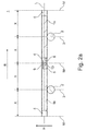
- Fig. 2b shows a detailed view of Fig. 2a ,
- a conveyor train 1 has a first conveyor 1a and a second conveyor 1b, which are arranged one behind the other in a direction of movement B. As a result, they have an identical longitudinal axis L.
- the two conveying means 1a, 1b each have a pair of wheels 2.
- the wheels 2 form the roll axis 3 of the respective conveyor 1a, 1b.
- the two conveying means 1 a, 1 b each have a first, rear, curved coupling element 4 in the direction of movement B at the rear end and, opposite the front end, a second, front, curved coupling element 5.
- the two coupling elements 4, 5 each have an upper spacer 11a, 12a, a middle spacer 11b, 12b and a lower spacer 11c, 12c, which each touch in the direction of the longitudinal axis L.
- the spacers 11a, 11b, 11c, 12a, 12b, 12c are spaced from each other.
- ropes 6, 8 run counter to each other in opposite directions.
- the ropes 6, 8 are made of steel and thus as inelastic as possible to avoid stretching or stretching.
- the ropes 6, 8 are with their ends respectively between the coupling element 4, 5 and the conveyor 1a, 1b by fasteners 7a, 7b, 9a, 9b arranged.
- the ends of the cables 6, 8 have for this purpose eyelets which are hooked into hooks of the fasteners 7a, 7b, 9a, 9b, which can then be tensioned by means of a screw mechanism in order to avoid play between the conveying means 1a, 1b minimize.
- the point of intersection 10 or also intersection point 10 of the two cables 6, 8 is the coupling point 10 of the two conveying means 1a, 1b, which also represents the pivot point 10 or instantaneous pole 10 of the two conveying means 1a, 1b relative to one another.
- the conveying means 1a, 1b or their coupling elements 4, 5 and rolling axles 3 are formed or arranged such that the roll axis 3 of a conveyor 1a, 1b to the coupling point 10 and its axis M with a preceding conveying means 1a, 1b and to a trailing conveyor 1a, 1b has the same distance X when driving straight ahead. As a result, a punctual driving behavior when driving straight ahead can be supported.
- the two conveying means 1a, 1b are interconnected by a cruciate ligament joint 4-12c, wherein in this embodiment, ropes 6, 8 instead of bands 6, 8 are used.
- a first cable 6 is fastened with one end via a fastening 7a on the first conveyor 1a.
- the first cable 6 now extends around the arcuate contour of the first, rear coupling element 4 of the first conveyor 1a in the recess between the upper spacer 11a and the middle spacer 11b (see FIG. Fig.
- the second cable 8 runs from a first attachment 9a on the first conveyor 1a around the arcuate contour of the first, rear coupling element 4 of the first conveyor 1a in the recess between the middle spacer 11b and the lower spacer 11c (see FIG. Fig. 2b ) and changes at the coupling point 10 into the corresponding recess between the middle spacer 12b and the lower spacer 12c of the second front coupling segment 5 of the second conveyor 1b.
- the second cable 8 now also runs around it until it is fastened to the second conveyor 1b via a fastening 9b.
- the two cables 6, 8, viewed from above, cross at their respective change between the two coupling elements 4, 5 in opposite directions at the point of intersection 10 or intersection point 10.
- This arrangement allows a coupling of the two conveying means 1a, 1b by means of a cruciate ligament joint 4-12c with the corresponding advantages.
- the bow shapes of the coupling elements 4, 5 are designed such that they are evenly when cornering can roll off.
- the coupling elements 4, 5 are formed as short as possible in the direction of the longitudinal axis L in order to keep the distance between the conveying means 1a, 1b as small as possible.
- Fig. 3a shows a schematic plan view of two inventively coupled conveyor 1a, 1b in cornering with a small angle of rotation ⁇ to each other.
- Fig. 3b shows a detailed view of Fig. 3a .
- the coupling point 10 shifts into the curve while the coupling elements 4, 5 roll over one another via their spacers 11a, 11b, 11c, 12a, 12b, 12c.
- the distance between the coupling point 10 or its axis M to the two adjacent rolling axes 3 is reduced to the distance Y, which, however, remains the same in both directions.
- Fig. 4 shows a schematic plan view of two inventively coupled conveyor 1a, 1b in cornering with a rotation angle ⁇ above 90 ° to each other.
- the coupling point 10 has moved further into the curve and the distance Y shortens even further.
- the conveyor 1a, 1b remain controllably connected to each other in this movement and by a towing vehicle (not shown) movable.
Landscapes
- Engineering & Computer Science (AREA)
- Transportation (AREA)
- Mechanical Engineering (AREA)
- Chain Conveyers (AREA)
- Intermediate Stations On Conveyors (AREA)
Applications Claiming Priority (1)
| Application Number | Priority Date | Filing Date | Title |
|---|---|---|---|
| DE102014018671.7A DE102014018671A1 (de) | 2014-12-18 | 2014-12-18 | Fördermittelzug mit Kopplungskinematik |
Publications (3)
| Publication Number | Publication Date |
|---|---|
| EP3034334A2 true EP3034334A2 (fr) | 2016-06-22 |
| EP3034334A3 EP3034334A3 (fr) | 2016-06-29 |
| EP3034334B1 EP3034334B1 (fr) | 2019-10-02 |
Family
ID=55182189
Family Applications (1)
| Application Number | Title | Priority Date | Filing Date |
|---|---|---|---|
| EP15199795.4A Active EP3034334B1 (fr) | 2014-12-18 | 2015-12-14 | Traction de moyen de transport dotee d'une tringlerie d'accouplement |
Country Status (2)
| Country | Link |
|---|---|
| EP (1) | EP3034334B1 (fr) |
| DE (1) | DE102014018671A1 (fr) |
Cited By (5)
| Publication number | Priority date | Publication date | Assignee | Title |
|---|---|---|---|---|
| CN108621166A (zh) * | 2018-06-15 | 2018-10-09 | 顺丰科技有限公司 | 多机器人无人配送系统和方法 |
| DE102017216205A1 (de) * | 2017-09-13 | 2018-10-31 | Bayerische Motoren Werke Aktiengesellschaft | Transportzellenverbund enthaltendes Fahrzeug |
| EP3695991A1 (fr) * | 2019-02-17 | 2020-08-19 | A&A Logistik-Equipment GmbH & Co. KG | Système de train routier ou convoi remorqué |
| CN113443370A (zh) * | 2020-03-26 | 2021-09-28 | 德国邮政股份公司 | 铰接连接输送和/或分拣设备的两个元件的联接装置和对应的输送和/或分拣设备 |
| US20240017707A1 (en) * | 2020-11-16 | 2024-01-18 | Getplus S.R.L. | Modular braking device |
Citations (8)
| Publication number | Priority date | Publication date | Assignee | Title |
|---|---|---|---|---|
| FR526803A (fr) | 1920-10-30 | 1921-10-14 | Gaston Devaux | Attelage à barres croisées pour remorques permettant les tournants corrects |
| CH569605A5 (en) | 1973-09-17 | 1975-11-28 | Frech Gebr Ag | Articulated traction vehicle and trailer system - has single axle trailers for ensuring good vehicle lock |
| DE3639668A1 (de) | 1985-11-25 | 1987-06-11 | Channel Kor Systems Inc | Paneelvorrichtung |
| GB2189290A (en) | 1986-03-20 | 1987-10-21 | Como & Co Limited | Connecting means for panels |
| DE4114315A1 (de) | 1990-05-17 | 1991-11-21 | Hans Prof Roericht | Verfahren zur herstellung einer scharnierverbindung fuer die gelenkige verbindung von flaechenelementen |
| WO1994022342A1 (fr) | 1993-04-05 | 1994-10-13 | Hans Roericht | Boitier pour objets |
| EP1342594A2 (fr) | 2002-03-02 | 2003-09-10 | HÜBNER GmbH | Ensemble d'articulation entre deux parties d'un véhicule articulé |
| DE102011106842A1 (de) | 2011-07-07 | 2013-01-10 | A & A Logistik-Equipment GmbH & Co. KG | Routenzug |
Family Cites Families (6)
| Publication number | Priority date | Publication date | Assignee | Title |
|---|---|---|---|---|
| DE189740C (fr) * | ||||
| DE370263C (de) * | 1923-03-01 | Loring Bartlett Doe | Zugverbindung zwischen einem Kraftfahrzeug und einem Lastfahrzeug, insbesondere einem Pflug | |
| US1234068A (en) * | 1916-11-13 | 1917-07-17 | William P Negus | Composite road-wagon. |
| DE958619C (de) * | 1954-10-07 | 1957-02-21 | Kaessbohrer Fahrzeug Karl | Fahrzeugkupplung |
| FR2445775A1 (fr) * | 1979-01-03 | 1980-08-01 | Feuvray Alain | Dispositif d'attelage pour remorque et remorque comprenant un tel dispositif |
| FR2517604A1 (fr) * | 1981-12-09 | 1983-06-10 | Verdier Jean Jacques | Dispositif d'attelage pour vehicules |
-
2014
- 2014-12-18 DE DE102014018671.7A patent/DE102014018671A1/de not_active Withdrawn
-
2015
- 2015-12-14 EP EP15199795.4A patent/EP3034334B1/fr active Active
Patent Citations (8)
| Publication number | Priority date | Publication date | Assignee | Title |
|---|---|---|---|---|
| FR526803A (fr) | 1920-10-30 | 1921-10-14 | Gaston Devaux | Attelage à barres croisées pour remorques permettant les tournants corrects |
| CH569605A5 (en) | 1973-09-17 | 1975-11-28 | Frech Gebr Ag | Articulated traction vehicle and trailer system - has single axle trailers for ensuring good vehicle lock |
| DE3639668A1 (de) | 1985-11-25 | 1987-06-11 | Channel Kor Systems Inc | Paneelvorrichtung |
| GB2189290A (en) | 1986-03-20 | 1987-10-21 | Como & Co Limited | Connecting means for panels |
| DE4114315A1 (de) | 1990-05-17 | 1991-11-21 | Hans Prof Roericht | Verfahren zur herstellung einer scharnierverbindung fuer die gelenkige verbindung von flaechenelementen |
| WO1994022342A1 (fr) | 1993-04-05 | 1994-10-13 | Hans Roericht | Boitier pour objets |
| EP1342594A2 (fr) | 2002-03-02 | 2003-09-10 | HÜBNER GmbH | Ensemble d'articulation entre deux parties d'un véhicule articulé |
| DE102011106842A1 (de) | 2011-07-07 | 2013-01-10 | A & A Logistik-Equipment GmbH & Co. KG | Routenzug |
Cited By (9)
| Publication number | Priority date | Publication date | Assignee | Title |
|---|---|---|---|---|
| DE102017216205A1 (de) * | 2017-09-13 | 2018-10-31 | Bayerische Motoren Werke Aktiengesellschaft | Transportzellenverbund enthaltendes Fahrzeug |
| CN108621166A (zh) * | 2018-06-15 | 2018-10-09 | 顺丰科技有限公司 | 多机器人无人配送系统和方法 |
| CN108621166B (zh) * | 2018-06-15 | 2024-06-04 | 顺丰科技有限公司 | 多机器人无人配送系统和方法 |
| EP3695991A1 (fr) * | 2019-02-17 | 2020-08-19 | A&A Logistik-Equipment GmbH & Co. KG | Système de train routier ou convoi remorqué |
| EP3695991B1 (fr) * | 2019-02-17 | 2024-04-17 | K. Hartwall GmbH | Système de train routier ou convoi remorqué |
| CN113443370A (zh) * | 2020-03-26 | 2021-09-28 | 德国邮政股份公司 | 铰接连接输送和/或分拣设备的两个元件的联接装置和对应的输送和/或分拣设备 |
| EP3885287A1 (fr) * | 2020-03-26 | 2021-09-29 | Deutsche Post AG | Dispositif d'accouplement destiné à la liaison articulée de deux éléments d'un dispositif de transport et/ou de triage et dispositif de transport et/ou de triage correspondant |
| CN113443370B (zh) * | 2020-03-26 | 2023-06-23 | 德国邮政股份公司 | 铰接连接输送和/或分拣设备的两个元件的联接装置和对应的输送和/或分拣设备 |
| US20240017707A1 (en) * | 2020-11-16 | 2024-01-18 | Getplus S.R.L. | Modular braking device |
Also Published As
| Publication number | Publication date |
|---|---|
| EP3034334A3 (fr) | 2016-06-29 |
| EP3034334B1 (fr) | 2019-10-02 |
| DE102014018671A1 (de) | 2016-06-23 |
Similar Documents
| Publication | Publication Date | Title |
|---|---|---|
| EP2218661B1 (fr) | Convoyeur de triage | |
| EP3034334B1 (fr) | Traction de moyen de transport dotee d'une tringlerie d'accouplement | |
| EP1911716A2 (fr) | Grue | |
| DE102014004681B4 (de) | Fördermittelzug mit Schlingerunterdrückung | |
| DE202011003760U1 (de) | Transportvorrichtung mit Laufwagen | |
| DE202017007208U1 (de) | Transportanhängerverbund und Transportanhängerzug mit mindestens zwei solchen Transportanhängerverbunden | |
| EP3159288A1 (fr) | Convoyeur de tri | |
| DE1680325C3 (de) | Gleiskette für geländegängige Fahrzeuge, insbesondere Panzerkampfwagen | |
| DE2100048A1 (de) | Federnde Achsaufhängung für Kraftfahrzeuge | |
| DE925814C (de) | Doppellaschenkette fuer endlose Foerderer | |
| DE969050C (de) | Endlose Foerderer, insbesondere fuer den Grubenbetrieb | |
| DE202012007693U1 (de) | Transportwagen | |
| DE3709409C2 (de) | Mehrgliedrige Traversenzugkatze | |
| DE60203046T2 (de) | Gelenkiges Raupenlaufwerk | |
| DE857390C (de) | Kupplung zum Ankuppeln eines nur auf einer Hinterachse laufenden Schienenfahrzeugs an ein auf mindestens vier Raedern laufendes Fahrzeug (z. B. an eine Lokomotive) | |
| DE2153866C3 (de) | Gelenkwagen, insbesondere Schienen-Gelenkwagen | |
| EP3012170A1 (fr) | Chassis de vehicules ferroviaire | |
| WO2015176795A1 (fr) | Wagon de chargement de matières en vrac | |
| EP2537782B1 (fr) | Moyen de transport pour milieux granuleux | |
| DE1481999A1 (de) | Schleppvorrichtung fuer Flugzeuge | |
| DE3220484A1 (de) | Wagen einer schienenflurbahn | |
| AT7527U1 (de) | Anhängbares grossflächenmähwerk | |
| DE69800392T2 (de) | Radaufhängung für ein Fahrzeug | |
| DE881911C (de) | Geraet fuer den Strassen- und Schienentransport von schweren Lasten | |
| DE102018123133A1 (de) | Rahmensystem |
Legal Events
| Date | Code | Title | Description |
|---|---|---|---|
| PUAI | Public reference made under article 153(3) epc to a published international application that has entered the european phase |
Free format text: ORIGINAL CODE: 0009012 |
|
| PUAL | Search report despatched |
Free format text: ORIGINAL CODE: 0009013 |
|
| AK | Designated contracting states |
Kind code of ref document: A2 Designated state(s): AL AT BE BG CH CY CZ DE DK EE ES FI FR GB GR HR HU IE IS IT LI LT LU LV MC MK MT NL NO PL PT RO RS SE SI SK SM TR |
|
| AX | Request for extension of the european patent |
Extension state: BA ME |
|
| AK | Designated contracting states |
Kind code of ref document: A3 Designated state(s): AL AT BE BG CH CY CZ DE DK EE ES FI FR GB GR HR HU IE IS IT LI LT LU LV MC MK MT NL NO PL PT RO RS SE SI SK SM TR |
|
| AX | Request for extension of the european patent |
Extension state: BA ME |
|
| RIC1 | Information provided on ipc code assigned before grant |
Ipc: B60D 1/48 20060101AFI20160525BHEP Ipc: B60D 1/18 20060101ALI20160525BHEP Ipc: B60D 1/173 20060101ALI20160525BHEP |
|
| STAA | Information on the status of an ep patent application or granted ep patent |
Free format text: STATUS: REQUEST FOR EXAMINATION WAS MADE |
|
| 17P | Request for examination filed |
Effective date: 20170102 |
|
| RBV | Designated contracting states (corrected) |
Designated state(s): AL AT BE BG CH CY CZ DE DK EE ES FI FR GB GR HR HU IE IS IT LI LT LU LV MC MK MT NL NO PL PT RO RS SE SI SK SM TR |
|
| STAA | Information on the status of an ep patent application or granted ep patent |
Free format text: STATUS: EXAMINATION IS IN PROGRESS |
|
| 17Q | First examination report despatched |
Effective date: 20181008 |
|
| GRAP | Despatch of communication of intention to grant a patent |
Free format text: ORIGINAL CODE: EPIDOSNIGR1 |
|
| STAA | Information on the status of an ep patent application or granted ep patent |
Free format text: STATUS: GRANT OF PATENT IS INTENDED |
|
| INTG | Intention to grant announced |
Effective date: 20190709 |
|
| GRAS | Grant fee paid |
Free format text: ORIGINAL CODE: EPIDOSNIGR3 |
|
| GRAA | (expected) grant |
Free format text: ORIGINAL CODE: 0009210 |
|
| STAA | Information on the status of an ep patent application or granted ep patent |
Free format text: STATUS: THE PATENT HAS BEEN GRANTED |
|
| AK | Designated contracting states |
Kind code of ref document: B1 Designated state(s): AL AT BE BG CH CY CZ DE DK EE ES FI FR GB GR HR HU IE IS IT LI LT LU LV MC MK MT NL NO PL PT RO RS SE SI SK SM TR |
|
| REG | Reference to a national code |
Ref country code: GB Ref legal event code: FG4D Free format text: NOT ENGLISH |
|
| REG | Reference to a national code |
Ref country code: CH Ref legal event code: EP Ref country code: AT Ref legal event code: REF Ref document number: 1185788 Country of ref document: AT Kind code of ref document: T Effective date: 20191015 |
|
| REG | Reference to a national code |
Ref country code: DE Ref legal event code: R096 Ref document number: 502015010508 Country of ref document: DE |
|
| REG | Reference to a national code |
Ref country code: IE Ref legal event code: FG4D Free format text: LANGUAGE OF EP DOCUMENT: GERMAN |
|
| REG | Reference to a national code |
Ref country code: NL Ref legal event code: FP |
|
| REG | Reference to a national code |
Ref country code: LT Ref legal event code: MG4D |
|
| PG25 | Lapsed in a contracting state [announced via postgrant information from national office to epo] |
Ref country code: ES Free format text: LAPSE BECAUSE OF FAILURE TO SUBMIT A TRANSLATION OF THE DESCRIPTION OR TO PAY THE FEE WITHIN THE PRESCRIBED TIME-LIMIT Effective date: 20191002 Ref country code: LT Free format text: LAPSE BECAUSE OF FAILURE TO SUBMIT A TRANSLATION OF THE DESCRIPTION OR TO PAY THE FEE WITHIN THE PRESCRIBED TIME-LIMIT Effective date: 20191002 Ref country code: GR Free format text: LAPSE BECAUSE OF FAILURE TO SUBMIT A TRANSLATION OF THE DESCRIPTION OR TO PAY THE FEE WITHIN THE PRESCRIBED TIME-LIMIT Effective date: 20200103 Ref country code: NO Free format text: LAPSE BECAUSE OF FAILURE TO SUBMIT A TRANSLATION OF THE DESCRIPTION OR TO PAY THE FEE WITHIN THE PRESCRIBED TIME-LIMIT Effective date: 20200102 Ref country code: PL Free format text: LAPSE BECAUSE OF FAILURE TO SUBMIT A TRANSLATION OF THE DESCRIPTION OR TO PAY THE FEE WITHIN THE PRESCRIBED TIME-LIMIT Effective date: 20191002 Ref country code: FI Free format text: LAPSE BECAUSE OF FAILURE TO SUBMIT A TRANSLATION OF THE DESCRIPTION OR TO PAY THE FEE WITHIN THE PRESCRIBED TIME-LIMIT Effective date: 20191002 Ref country code: BG Free format text: LAPSE BECAUSE OF FAILURE TO SUBMIT A TRANSLATION OF THE DESCRIPTION OR TO PAY THE FEE WITHIN THE PRESCRIBED TIME-LIMIT Effective date: 20200102 Ref country code: LV Free format text: LAPSE BECAUSE OF FAILURE TO SUBMIT A TRANSLATION OF THE DESCRIPTION OR TO PAY THE FEE WITHIN THE PRESCRIBED TIME-LIMIT Effective date: 20191002 Ref country code: PT Free format text: LAPSE BECAUSE OF FAILURE TO SUBMIT A TRANSLATION OF THE DESCRIPTION OR TO PAY THE FEE WITHIN THE PRESCRIBED TIME-LIMIT Effective date: 20200203 Ref country code: SE Free format text: LAPSE BECAUSE OF FAILURE TO SUBMIT A TRANSLATION OF THE DESCRIPTION OR TO PAY THE FEE WITHIN THE PRESCRIBED TIME-LIMIT Effective date: 20191002 |
|
| PG25 | Lapsed in a contracting state [announced via postgrant information from national office to epo] |
Ref country code: RS Free format text: LAPSE BECAUSE OF FAILURE TO SUBMIT A TRANSLATION OF THE DESCRIPTION OR TO PAY THE FEE WITHIN THE PRESCRIBED TIME-LIMIT Effective date: 20191002 Ref country code: HR Free format text: LAPSE BECAUSE OF FAILURE TO SUBMIT A TRANSLATION OF THE DESCRIPTION OR TO PAY THE FEE WITHIN THE PRESCRIBED TIME-LIMIT Effective date: 20191002 Ref country code: IS Free format text: LAPSE BECAUSE OF FAILURE TO SUBMIT A TRANSLATION OF THE DESCRIPTION OR TO PAY THE FEE WITHIN THE PRESCRIBED TIME-LIMIT Effective date: 20200224 Ref country code: CZ Free format text: LAPSE BECAUSE OF FAILURE TO SUBMIT A TRANSLATION OF THE DESCRIPTION OR TO PAY THE FEE WITHIN THE PRESCRIBED TIME-LIMIT Effective date: 20191002 |
|
| PG25 | Lapsed in a contracting state [announced via postgrant information from national office to epo] |
Ref country code: AL Free format text: LAPSE BECAUSE OF FAILURE TO SUBMIT A TRANSLATION OF THE DESCRIPTION OR TO PAY THE FEE WITHIN THE PRESCRIBED TIME-LIMIT Effective date: 20191002 |
|
| REG | Reference to a national code |
Ref country code: DE Ref legal event code: R097 Ref document number: 502015010508 Country of ref document: DE |
|
| PG2D | Information on lapse in contracting state deleted |
Ref country code: IS |
|
| PG25 | Lapsed in a contracting state [announced via postgrant information from national office to epo] |
Ref country code: EE Free format text: LAPSE BECAUSE OF FAILURE TO SUBMIT A TRANSLATION OF THE DESCRIPTION OR TO PAY THE FEE WITHIN THE PRESCRIBED TIME-LIMIT Effective date: 20191002 Ref country code: DK Free format text: LAPSE BECAUSE OF FAILURE TO SUBMIT A TRANSLATION OF THE DESCRIPTION OR TO PAY THE FEE WITHIN THE PRESCRIBED TIME-LIMIT Effective date: 20191002 Ref country code: RO Free format text: LAPSE BECAUSE OF FAILURE TO SUBMIT A TRANSLATION OF THE DESCRIPTION OR TO PAY THE FEE WITHIN THE PRESCRIBED TIME-LIMIT Effective date: 20191002 Ref country code: IS Free format text: LAPSE BECAUSE OF FAILURE TO SUBMIT A TRANSLATION OF THE DESCRIPTION OR TO PAY THE FEE WITHIN THE PRESCRIBED TIME-LIMIT Effective date: 20200202 |
|
| REG | Reference to a national code |
Ref country code: CH Ref legal event code: PL |
|
| PLBE | No opposition filed within time limit |
Free format text: ORIGINAL CODE: 0009261 |
|
| STAA | Information on the status of an ep patent application or granted ep patent |
Free format text: STATUS: NO OPPOSITION FILED WITHIN TIME LIMIT |
|
| REG | Reference to a national code |
Ref country code: BE Ref legal event code: MM Effective date: 20191231 |
|
| PG25 | Lapsed in a contracting state [announced via postgrant information from national office to epo] |
Ref country code: SK Free format text: LAPSE BECAUSE OF FAILURE TO SUBMIT A TRANSLATION OF THE DESCRIPTION OR TO PAY THE FEE WITHIN THE PRESCRIBED TIME-LIMIT Effective date: 20191002 Ref country code: MC Free format text: LAPSE BECAUSE OF FAILURE TO SUBMIT A TRANSLATION OF THE DESCRIPTION OR TO PAY THE FEE WITHIN THE PRESCRIBED TIME-LIMIT Effective date: 20191002 Ref country code: SM Free format text: LAPSE BECAUSE OF FAILURE TO SUBMIT A TRANSLATION OF THE DESCRIPTION OR TO PAY THE FEE WITHIN THE PRESCRIBED TIME-LIMIT Effective date: 20191002 |
|
| 26N | No opposition filed |
Effective date: 20200703 |
|
| PG25 | Lapsed in a contracting state [announced via postgrant information from national office to epo] |
Ref country code: LU Free format text: LAPSE BECAUSE OF NON-PAYMENT OF DUE FEES Effective date: 20191214 Ref country code: IE Free format text: LAPSE BECAUSE OF NON-PAYMENT OF DUE FEES Effective date: 20191214 |
|
| PG25 | Lapsed in a contracting state [announced via postgrant information from national office to epo] |
Ref country code: CH Free format text: LAPSE BECAUSE OF NON-PAYMENT OF DUE FEES Effective date: 20191231 Ref country code: SI Free format text: LAPSE BECAUSE OF FAILURE TO SUBMIT A TRANSLATION OF THE DESCRIPTION OR TO PAY THE FEE WITHIN THE PRESCRIBED TIME-LIMIT Effective date: 20191002 Ref country code: BE Free format text: LAPSE BECAUSE OF NON-PAYMENT OF DUE FEES Effective date: 20191231 Ref country code: LI Free format text: LAPSE BECAUSE OF NON-PAYMENT OF DUE FEES Effective date: 20191231 |
|
| PG25 | Lapsed in a contracting state [announced via postgrant information from national office to epo] |
Ref country code: CY Free format text: LAPSE BECAUSE OF FAILURE TO SUBMIT A TRANSLATION OF THE DESCRIPTION OR TO PAY THE FEE WITHIN THE PRESCRIBED TIME-LIMIT Effective date: 20191002 |
|
| PG25 | Lapsed in a contracting state [announced via postgrant information from national office to epo] |
Ref country code: MT Free format text: LAPSE BECAUSE OF FAILURE TO SUBMIT A TRANSLATION OF THE DESCRIPTION OR TO PAY THE FEE WITHIN THE PRESCRIBED TIME-LIMIT Effective date: 20191002 Ref country code: HU Free format text: LAPSE BECAUSE OF FAILURE TO SUBMIT A TRANSLATION OF THE DESCRIPTION OR TO PAY THE FEE WITHIN THE PRESCRIBED TIME-LIMIT; INVALID AB INITIO Effective date: 20151214 |
|
| REG | Reference to a national code |
Ref country code: AT Ref legal event code: MM01 Ref document number: 1185788 Country of ref document: AT Kind code of ref document: T Effective date: 20201214 |
|
| PG25 | Lapsed in a contracting state [announced via postgrant information from national office to epo] |
Ref country code: AT Free format text: LAPSE BECAUSE OF NON-PAYMENT OF DUE FEES Effective date: 20201214 |
|
| PG25 | Lapsed in a contracting state [announced via postgrant information from national office to epo] |
Ref country code: TR Free format text: LAPSE BECAUSE OF FAILURE TO SUBMIT A TRANSLATION OF THE DESCRIPTION OR TO PAY THE FEE WITHIN THE PRESCRIBED TIME-LIMIT Effective date: 20191002 |
|
| PG25 | Lapsed in a contracting state [announced via postgrant information from national office to epo] |
Ref country code: MK Free format text: LAPSE BECAUSE OF FAILURE TO SUBMIT A TRANSLATION OF THE DESCRIPTION OR TO PAY THE FEE WITHIN THE PRESCRIBED TIME-LIMIT Effective date: 20191002 |
|
| REG | Reference to a national code |
Ref country code: DE Ref legal event code: R081 Ref document number: 502015010508 Country of ref document: DE Owner name: K. HARTWALL GMBH, DE Free format text: FORMER OWNER: A&A LOGISTIK-EQUIPMENT GMBH & CO. KG, 21258 HEIDENAU, DE |
|
| REG | Reference to a national code |
Ref country code: GB Ref legal event code: 732E Free format text: REGISTERED BETWEEN 20240418 AND 20240424 |
|
| PGFP | Annual fee paid to national office [announced via postgrant information from national office to epo] |
Ref country code: GB Payment date: 20251219 Year of fee payment: 11 |
|
| PGFP | Annual fee paid to national office [announced via postgrant information from national office to epo] |
Ref country code: IT Payment date: 20251223 Year of fee payment: 11 |
|
| PGFP | Annual fee paid to national office [announced via postgrant information from national office to epo] |
Ref country code: NL Payment date: 20251219 Year of fee payment: 11 Ref country code: FR Payment date: 20251223 Year of fee payment: 11 |
|
| PGFP | Annual fee paid to national office [announced via postgrant information from national office to epo] |
Ref country code: DE Payment date: 20251231 Year of fee payment: 11 |
|
| REG | Reference to a national code |
Ref country code: DE Ref legal event code: R081 Ref document number: 502015010508 Country of ref document: DE Owner name: K. HARTWALL GMBH, DE Free format text: FORMER OWNER: K. HARTWALL GMBH, 21258 HEIDENAU, DE |