EP3034408A1 - Auf fächern basiertes einlasspartikelabscheidersystem - Google Patents
Auf fächern basiertes einlasspartikelabscheidersystem Download PDFInfo
- Publication number
- EP3034408A1 EP3034408A1 EP15199431.6A EP15199431A EP3034408A1 EP 3034408 A1 EP3034408 A1 EP 3034408A1 EP 15199431 A EP15199431 A EP 15199431A EP 3034408 A1 EP3034408 A1 EP 3034408A1
- Authority
- EP
- European Patent Office
- Prior art keywords
- diffuser
- compartment
- air inlet
- apu
- inlet
- Prior art date
- Legal status (The legal status is an assumption and is not a legal conclusion. Google has not performed a legal analysis and makes no representation as to the accuracy of the status listed.)
- Granted
Links
Images



Classifications
-
- F—MECHANICAL ENGINEERING; LIGHTING; HEATING; WEAPONS; BLASTING
- F01—MACHINES OR ENGINES IN GENERAL; ENGINE PLANTS IN GENERAL; STEAM ENGINES
- F01D—NON-POSITIVE DISPLACEMENT MACHINES OR ENGINES, e.g. STEAM TURBINES
- F01D1/00—Non-positive-displacement machines or engines, e.g. steam turbines
- F01D1/18—Non-positive-displacement machines or engines, e.g. steam turbines without stationary working-fluid guiding means
- F01D1/20—Non-positive-displacement machines or engines, e.g. steam turbines without stationary working-fluid guiding means traversed by the working-fluid substantially axially
-
- B—PERFORMING OPERATIONS; TRANSPORTING
- B64—AIRCRAFT; AVIATION; COSMONAUTICS
- B64D—EQUIPMENT FOR FITTING IN OR TO AIRCRAFT; FLIGHT SUITS; PARACHUTES; ARRANGEMENT OR MOUNTING OF POWER PLANTS OR PROPULSION TRANSMISSIONS IN AIRCRAFT
- B64D33/00—Arrangement in aircraft of power plant parts or auxiliaries not otherwise provided for
- B64D33/02—Arrangement in aircraft of power plant parts or auxiliaries not otherwise provided for of combustion air intakes
-
- B—PERFORMING OPERATIONS; TRANSPORTING
- B64—AIRCRAFT; AVIATION; COSMONAUTICS
- B64D—EQUIPMENT FOR FITTING IN OR TO AIRCRAFT; FLIGHT SUITS; PARACHUTES; ARRANGEMENT OR MOUNTING OF POWER PLANTS OR PROPULSION TRANSMISSIONS IN AIRCRAFT
- B64D33/00—Arrangement in aircraft of power plant parts or auxiliaries not otherwise provided for
-
- B—PERFORMING OPERATIONS; TRANSPORTING
- B64—AIRCRAFT; AVIATION; COSMONAUTICS
- B64D—EQUIPMENT FOR FITTING IN OR TO AIRCRAFT; FLIGHT SUITS; PARACHUTES; ARRANGEMENT OR MOUNTING OF POWER PLANTS OR PROPULSION TRANSMISSIONS IN AIRCRAFT
- B64D41/00—Power installations for auxiliary purposes
-
- B—PERFORMING OPERATIONS; TRANSPORTING
- B64—AIRCRAFT; AVIATION; COSMONAUTICS
- B64D—EQUIPMENT FOR FITTING IN OR TO AIRCRAFT; FLIGHT SUITS; PARACHUTES; ARRANGEMENT OR MOUNTING OF POWER PLANTS OR PROPULSION TRANSMISSIONS IN AIRCRAFT
- B64D33/00—Arrangement in aircraft of power plant parts or auxiliaries not otherwise provided for
- B64D33/02—Arrangement in aircraft of power plant parts or auxiliaries not otherwise provided for of combustion air intakes
- B64D2033/0213—Arrangement in aircraft of power plant parts or auxiliaries not otherwise provided for of combustion air intakes specially adapted for auxiliary power units (APU's)
-
- B—PERFORMING OPERATIONS; TRANSPORTING
- B64—AIRCRAFT; AVIATION; COSMONAUTICS
- B64D—EQUIPMENT FOR FITTING IN OR TO AIRCRAFT; FLIGHT SUITS; PARACHUTES; ARRANGEMENT OR MOUNTING OF POWER PLANTS OR PROPULSION TRANSMISSIONS IN AIRCRAFT
- B64D33/00—Arrangement in aircraft of power plant parts or auxiliaries not otherwise provided for
- B64D33/02—Arrangement in aircraft of power plant parts or auxiliaries not otherwise provided for of combustion air intakes
- B64D2033/0246—Arrangement in aircraft of power plant parts or auxiliaries not otherwise provided for of combustion air intakes comprising particle separators
-
- B—PERFORMING OPERATIONS; TRANSPORTING
- B64—AIRCRAFT; AVIATION; COSMONAUTICS
- B64D—EQUIPMENT FOR FITTING IN OR TO AIRCRAFT; FLIGHT SUITS; PARACHUTES; ARRANGEMENT OR MOUNTING OF POWER PLANTS OR PROPULSION TRANSMISSIONS IN AIRCRAFT
- B64D41/00—Power installations for auxiliary purposes
- B64D2041/002—Mounting arrangements for auxiliary power units (APU's)
Definitions
- the present invention generally relates to inlet particle separator systems for auxiliary power units (APUs), and more particularly relates to compartment based inlet particle separator systems for aircraft that include an APU system compartment.
- APUs auxiliary power units
- the main propulsion engines not only provide propulsion for the aircraft, but may also be used to drive various other rotating components such as, for example, generators, compressors, and pumps, to thereby supply electrical and/or pneumatic power.
- the main propulsion engines may not be capable of supplying the power needed for propulsion as well as the power to drive these other rotating components.
- many aircraft include an auxiliary power unit (APU) to supplement the main propulsion engines in providing electrical and/or pneumatic power.
- An APU may also be used to start the propulsion engines.
- APU-equipped aircraft are operated in environments that have a high concentration of fine dust particles (e.g., ⁇ 30 ⁇ m) suspended in the air.
- fine dust particles e.g., ⁇ 30 ⁇ m
- the fine dust particles can plug the holes in effusion cooled combustors, and can plug and corrode the high temperature turbine passages and hardware.
- IPS inlet particle separator system
- IPSs are designed to separate out relatively large particles (e.g., 100 ⁇ m ⁇ 1000 ⁇ m) but are less efficient at separating out fine particles. This is because these systems typically rely on particle inertia to move the particles into a separate collector and scavenge system. Fine particles, with relatively lower inertia, are much more inclined to follow the inlet airflow into the gas turbine engine, resulting in low separation efficiencies. Thus, many aircraft additionally include one or more systems to remove these fine particles. These additional systems include barrier filters (self-cleaning and non-self-cleaning), vortex panels, and multi-channel particle separator (MCPS) systems.
- barrier filters self-cleaning and non-self-cleaning
- vortex panels e.g., vortex panels
- MCPS multi-channel particle separator
- a compartment based inlet particle separator system for an aircraft that includes an auxiliary power unit (APU) system compartment, includes a separation barrier wall, a ram air inlet opening, a diffuser, and an inlet particle separator (IPS).
- the separation barrier wall is disposed within the APU system compartment and is configured to divide the APU system compartment into an air inlet compartment and an APU compartment.
- the separation barrier wall has an APU air inlet port formed therein that provides fluid communication between the air inlet compartment and the APU compartment.
- the ram air inlet opening is formed in the air inlet compartment for receiving a flow of ram air.
- the diffuser is disposed within the air inlet compartment and has a diffuser inlet and a diffuser outlet.
- the diffuser inlet is coupled to receive ram air from the ram air inlet opening.
- the diffuser outlet is in fluid communication with, and is configured to discharge ram air into, the air inlet compartment.
- the IPS is disposed within the air inlet compartment between the diffuser outlet and the APU air inlet port.
- an auxiliary power unit (APU) air inlet system for an aircraft that includes an APU system compartment includes a separation barrier wall, a ram air inlet opening, a diffuser, a plurality of flow control surfaces, and an inlet particle separator (IPS).
- the separation barrier wall is disposed within the APU system compartment and is configured to divide the APU system compartment into an air inlet compartment and an APU compartment.
- the separation barrier wall has an APU air inlet port formed therein that provides fluid communication between the air inlet compartment and the APU compartment.
- the ram air inlet opening is formed in the air inlet compartment for receiving a flow of ram air.
- the diffuser is disposed within the air inlet compartment and has a diffuser inlet, a diffuser outlet, and a bypass port disposed between the diffuser inlet and the diffuser outlet.
- the diffuser inlet is coupled to receive ram air from the ram air inlet opening.
- the diffuser outlet is in fluid communication with, and is configured to discharge ram air into, the air inlet compartment.
- the bypass port is in fluid communication with the APU air inlet port.
- the flow control surfaces are rotationally mounted within the diffuser and are movable between a first position, in which the flow control surfaces direct ram air through the bypass port and into the APU air inlet port, and a second position, in which the flow control surfaces direct ram air through the diffuser outlet.
- the inlet particle separator is disposed within the air inlet compartment between the diffuser outlet and the APU air inlet port.
- an auxiliary power unit (APU) air inlet system for an aircraft that includes an APU system compartment includes a separation barrier wall, a ram air inlet opening, a transverse diffuser, an inlet particle separator (IPS), and an APU.
- the separation barrier wall is disposed within the APU system compartment and is configured to divide the APU system compartment into an air inlet compartment and an APU compartment.
- the separation barrier wall has an APU air inlet port formed therein that provides fluid communication between the air inlet compartment and the APU compartment.
- the ram air inlet opening is formed in the air inlet compartment for receiving a flow of ram air.
- the transverse diffuser is disposed within the air inlet compartment and has a diffuser inlet and a diffuser outlet.
- the diffuser inlet is coupled to receive ram air from the ram air inlet opening.
- the diffuser outlet is in fluid communication with, and is configured to discharge ram air into, the air inlet compartment.
- the IPS is disposed within the air inlet compartment between the diffuser outlet and the APU air inlet port.
- the APU is disposed within the APU compartment, and has an air inlet in fluid communication with the APU air inlet port.
- FIG. 1 a cross-sectional schematic of a tail cone portion of an aircraft 100 is depicted.
- the aircraft 100 includes an auxiliary power unit (APU) system compartment 102 that is defined by an exterior surface 104, a forward firewall 106, and an aft firewall 108.
- the forward firewall 106 separates the APU system compartment 102 from other sections of the aircraft 100.
- the APU system compartment 102 is formed in the tailcone section of the aircraft 100. It will be appreciated, however, that this is merely exemplary, and that the APU system compartment 102 could be formed in any one of numerous other sections of the aircraft 100. It will additionally be appreciated that, depending on its location in the aircraft 100, the APU system compartment 102 may be defined by only one forward firewall 106 or aft firewall 108.
- the APU system compartment 102 additionally includes a separation barrier wall 112.
- the separation barrier wall 112 extends between the forward firewall 106 and the aft firewall 108, and divides the APU system compartment 102 into two separate compartments - an air inlet compartment 114 and an APU compartment 116.
- the separation barrier wall 112 has an APU air inlet port 115 formed therein that provides fluid communication between the air inlet compartment 114 and an inlet to an APU 128.
- a ram air inlet opening 118 is formed in the air inlet compartment 114 and extends through the exterior surface 104 of the aircraft 100.
- the ram air inlet opening 118 is configured to selectively receive a flow of ram air.
- an inlet door 122 and an inlet door actuator 124 are also preferably coupled to the APU system compartment 102.
- the inlet door 122 is coupled to receive an actuation drive force from the inlet door actuator 124 and is configured, in response to the actuation drive force, to move between a closed position and a plurality of open positions. In the closed position, the inlet door 122 prevents ram air from flowing into the ram air inlet opening 118. Conversely, in any one of the plurality of open positions, ram air may flow into the ram air inlet opening 118.
- FIG. 1 further depicts, a compartment based inlet particle separator system 120 is disposed within the air inlet compartment 114, and an APU 128 is disposed within the APU compartment 116.
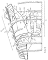
- a more detailed representation of example physical embodiments of the compartment based inlet particle separator system 120 are depicted in FIGS. 2 and 3 , and will momentarily be described. Before doing so, however, it is noted that the APU 128 has an air inlet 127 that is in fluid communication with the APU air inlet port 115 via an APU inlet duct 126 that extends from the APU 128.
- the compartment based inlet particle separator system 120 includes a diffuser 202 and an inlet particle separator (IPS) 204.
- the diffuser 202 is disposed within the air inlet compartment 114 and has a diffuser inlet 206 and a diffuser outlet 208.
- the diffuser inlet 206 is coupled to receive ram air from the ram air inlet opening 118, and the diffuser outlet 208 is in fluid communication with the air inlet compartment 114.
- the diffuser 202 is configured to reduce the velocity of the ram air that flows into the ram air inlet opening 118, and discharge the ram air, via the diffuser outlet 208, into the air inlet compartment 114. The reduced velocity reduces the loss in pressure of the ram air as it dumps from diffuser outlet 208 to air inlet compartment 114.
- the diffuser 202 may be variously disposed, but in the depicted embodiment it is disposed as close as possible to the wall (not illustrated) of the tailcone 102, while still allowing room from the structural ribs 212.
- the inlet door actuator 124 which is also not depicted in FIG. 2 , is preferably disposed in the opening 214 in the diffuser 202.
- the diffuser 202 is preferably configured as a transverse diffuser.
- the diffuser 202 includes an inner surface 216 that defines a cross sectional flow area that increases between the diffuser inlet 206 and the diffuser outlet 208. The increase in flow area is transverse to the external flow momentum.
- the diffuser 202 is additionally configured such that it has a first height and a first width adjacent to the diffuser inlet 206, and transitions to a second height and a second width adjacent to the diffuser outlet 208, where the first height is greater than the second height, and the first width is less than the second width.
- the IPS 204 is also disposed within the air inlet compartment 114. More specifically, it is disposed between the diffuser outlet 208 and the APU air inlet port 115, and divides the air inlet compartment 114 into two sections - a non-filtered section 218 and a filtered section 222.
- the non-filtered section 218 receives the ram air discharged from the diffuser 202
- the filtered section 222 receives filtered air discharged from the IPS 204.
- the IPS may be implemented using any one of numerous known IPSs that are configured to remove relatively fine dust particles (e.g., ⁇ 30 ⁇ m) and larger particles from the air discharged from the diffuser 202.
- suitable IPSs include vortex panels, barrier filters, and multi-channel particle separators (MCPSs).
- the IPS 204 is preferably disposed beneath the diffuser 202 and intercepts the airflow as it reverses direction inside the non-filtered section 218 of the air inlet compartment 114.
- the embodiment depicted in FIG. X illustrates how either a plurality of vortex panels or a plurality barrier filters are preferably disposed in the air inlet compartment.
- the vortex panels or barrier filters occupy the entire space below the diffuser 202 and above the separation barrier wall 112, and extend the entirety of the non-filtered section 218 of the air inlet compartment 114 from side wall to side wall (for clarity, the sidewalls are not depicted).
- the region that is not occupied by the IPS 204 includes a wall 224 to ensure all of the ram air discharged from the diffuser 202 flow through the IPS 204.
- the type of barrier filters may be either non-self-cleaning or self-cleaning. If non-self-cleaning barrier filters are used, the filters should be periodically checked, removed, and cleaned. Self-cleaning barrier filters are less desirable since this type of IPS 204 will typically occupy more space due to the additional hardware needed to implement the self-cleaning functionality.
- the vortex panel and barrier filter configurations require approximately the same amount of surface area to keep pressure losses to a minimum, and are thus very similar in size. As such, both configurations are illustrated using FIG. 2 .
- the MCPSs exhibit relatively lower pressure losses as compared to the vortex panels or barrier filters. Consequently, and as depicted in FIG. 3 , when the IPS 204 is implemented using MCPSs, the IPS 204 is smaller as compared to the other two types of IPSs 204. It will be appreciated that the MCPSs can be disposed in a horizontal or vertical arrangement. Though not depicted in FIG.
- the region that is not occupied by the IPS 204 includes the wall 224 to ensure all of the ram air discharged from the diffuser 202 flow through the IPS 204.
- a bellmouth structure 226 extends from the APU inlet port 115 into the air inlet compartment 114.
- the bellmouth structure 226 is preferably coupled to the APU inlet duct 126, and is configured to minimize losses as air flows into the APU inlet duct 126.
- the bellmouth structure 226 is preferably disposed above the separation barrier wall 112 to prevent any particles or FOD (foreign object debris) that may be lying on the separation barrier wall 112 to be sucked into the APU 128.
- FIGS. 2 and 3 An APU compartment cooling duct 228 is also depicted in FIGS. 2 and 3 .
- the APU compartment cooling duct 228 includes a cooling air inlet 232 and a cooling air outlet 234, and extends through the separation barrier wall 112.
- the cooling air inlet 232 is in fluid communication with the ram air inlet opening 118
- the cooling air outlet 234 is in fluid communication with the APU compartment 116.
- ambient air is drawn into the APU compartment 116 to provide APU compartment and oil cooling air, which is drawn via a non-illustrated APU exhaust eductor system.
- the compartment based inlet particle separator systems 120 depicted and described herein exhibit relatively low pressure loss, the systems nonetheless do exhibit some pressure loss.
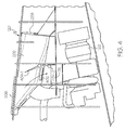
- the compartment based inlet particle separator system 120 additionally implements a bypass function.
- the diffuser 202 additionally includes a bypass port 402.
- the bypass port 402 is disposed between the diffuser inlet 206 and the diffuser outlet 208, and is in fluid communication with the APU air inlet port 115.
- the system 120 additionally includes a plurality of flow control surfaces 404 (404-1, 404-2).
- the flow control surfaces 404 are rotationally mounted within the diffuser 202 and are movable between a first position and a second position. In the first position, which is the position depicted in FIG. 4 , the flow control surfaces 404 direct ram air through the bypass port 402 and directly into the APU air inlet port 115. In the second position, which is the position depicted in FIG. 5 , the flow control surfaces 404 direct the ram air through the diffuser outlet 208, through the IPS 204, and into the APU air inlet port 115. Though not depicted in FIGS. 4 and 5 , the flow control surfaces 404 may be moved via the inlet door actuator 124 or a separate, non-illustrated actuator.
Landscapes
- Engineering & Computer Science (AREA)
- Aviation & Aerospace Engineering (AREA)
- Chemical & Material Sciences (AREA)
- Combustion & Propulsion (AREA)
- Mechanical Engineering (AREA)
- General Engineering & Computer Science (AREA)
- Separating Particles In Gases By Inertia (AREA)
- Cyclones (AREA)
Applications Claiming Priority (1)
| Application Number | Priority Date | Filing Date | Title |
|---|---|---|---|
| US14/573,926 US9719352B2 (en) | 2014-12-17 | 2014-12-17 | Compartment based inlet particle separator system |
Publications (2)
| Publication Number | Publication Date |
|---|---|
| EP3034408A1 true EP3034408A1 (de) | 2016-06-22 |
| EP3034408B1 EP3034408B1 (de) | 2017-04-05 |
Family
ID=54848510
Family Applications (1)
| Application Number | Title | Priority Date | Filing Date |
|---|---|---|---|
| EP15199431.6A Not-in-force EP3034408B1 (de) | 2014-12-17 | 2015-12-10 | Auf fächern basiertes einlasspartikelabscheidersystem |
Country Status (2)
| Country | Link |
|---|---|
| US (1) | US9719352B2 (de) |
| EP (1) | EP3034408B1 (de) |
Cited By (5)
| Publication number | Priority date | Publication date | Assignee | Title |
|---|---|---|---|---|
| US20160177724A1 (en) * | 2014-12-17 | 2016-06-23 | Honeywell International Inc. | Compartment based inlet particle separator system |
| EP3309077A1 (de) * | 2016-10-14 | 2018-04-18 | Pratt & Whitney Canada Corp. | Hilfsaggregateinlassanordnung mit partikelabscheider |
| US10279920B1 (en) * | 2018-02-27 | 2019-05-07 | Brant Farrell | Foreign object debris barrier filter apparatus for an aircraft intake system |
| US10508626B2 (en) | 2016-10-14 | 2019-12-17 | Pratt & Whitney Canada Corp. | Auxiliary power unit inlet assembly with filter |
| US10513344B2 (en) | 2016-10-14 | 2019-12-24 | Pratt & Whitney Canada Corp. | Auxiliary power unit assembly with removable inlet filter |
Families Citing this family (8)
| Publication number | Priority date | Publication date | Assignee | Title |
|---|---|---|---|---|
| ES2890374T3 (es) * | 2017-10-30 | 2022-01-18 | Airbus Operations Sl | Cono de cola de aeronave que incorpora una APU con admisión de aire anular |
| US11634228B2 (en) * | 2017-11-01 | 2023-04-25 | Sikorsky Aircraft Corporation | High volume flow management of cooling air |
| US11111024B2 (en) | 2018-01-12 | 2021-09-07 | Honeywell International Inc. | Foldable RAM air inlet filter |
| US11085372B2 (en) * | 2018-07-18 | 2021-08-10 | The Boeing Company | Anti-ice system exhaust air disruptor |
| US10865711B2 (en) | 2018-08-03 | 2020-12-15 | Pratt & Whitney Canada Corp. | Air inlet system for auxiliary power units |
| US10906660B2 (en) * | 2018-08-09 | 2021-02-02 | Bell Textron Inc. | Cowling inlet for sideward airflow |
| CN113950576A (zh) | 2019-03-29 | 2022-01-18 | 唐纳森公司 | 空气滤清器旁通组件和运行方法 |
| US11111855B2 (en) | 2019-05-23 | 2021-09-07 | Rolls-Royce North American Technologies Inc. | Inlet particle separator |
Citations (3)
| Publication number | Priority date | Publication date | Assignee | Title |
|---|---|---|---|---|
| EP1686058A1 (de) * | 2005-01-27 | 2006-08-02 | Honeywell International Inc. | Schalldämpfende Luftversorgung eines Flugzeughilfsaggregats |
| EP1847458A2 (de) * | 2006-04-20 | 2007-10-24 | Honeywell Inc. | Lufteinlassklappe mit Diffusor |
| WO2010077241A1 (en) * | 2008-12-30 | 2010-07-08 | Sikorsky Aircraft Corporation | Engine air particle separator |
Family Cites Families (30)
| Publication number | Priority date | Publication date | Assignee | Title |
|---|---|---|---|---|
| US3421296A (en) * | 1966-11-15 | 1969-01-14 | United Aircraft Corp | Engine inlet air particle separator |
| US3449891A (en) | 1966-11-15 | 1969-06-17 | United Aircraft Corp | Engine inlet air particle separator |
| US3673771A (en) * | 1970-11-23 | 1972-07-04 | Avco Corp | Multi-channel particle separator |
| US3952972A (en) | 1974-12-24 | 1976-04-27 | United Aircraft Of Canada Limited | Inertial separator |
| DE2605941C3 (de) | 1976-02-14 | 1980-10-30 | Mtu Motoren- Und Turbinen-Union Friedrichshafen Gmbh, 7990 Friedrichshafen | Gehäuse |
| US4250703A (en) | 1979-03-15 | 1981-02-17 | Avco Corporation | Swinging door particle separator and deicing system |
| US4304094A (en) | 1979-11-16 | 1981-12-08 | United Technologies Corp. | Engine air particle separator for use with gas turbine engine |
| US6264137B1 (en) | 2000-02-25 | 2001-07-24 | Honeywell International Inc. | Inlet vortex bustor and ice protector for auxiliary power units |
| US6595742B2 (en) * | 2000-10-02 | 2003-07-22 | Westar Corporation | Aircraft engine air filter and method |
| US6520738B2 (en) | 2001-03-15 | 2003-02-18 | Honeywell International, Inc. | Plenum entry bulk swirl generator |
| US6651929B2 (en) | 2001-10-29 | 2003-11-25 | Pratt & Whitney Canada Corp. | Passive cooling system for auxiliary power unit installation |
| DE10200459A1 (de) * | 2002-01-09 | 2003-07-24 | Airbus Gmbh | Lufteinlauf für ein Hilfstriebwerk in einem Flugzeug |
| US6824582B2 (en) | 2002-12-13 | 2004-11-30 | Westar Corporation | Filter system for turbine engine |
| US20060059891A1 (en) * | 2004-09-23 | 2006-03-23 | Honeywell International, Inc. | Quiet chevron/tab exhaust eductor system |
| US7344107B2 (en) * | 2004-10-26 | 2008-03-18 | The Boeing Company | Dual flow APU inlet and associated systems and methods |
| ES2273546B1 (es) | 2004-12-31 | 2008-03-16 | Airbus España, S.L. | Conducto de admision para un grupo electrogeno auxiliar con aletas guiadoras aeroacusticas. |
| US7600713B2 (en) * | 2005-03-04 | 2009-10-13 | Honeywell International Inc. | Pre-hung inlet door system |
| US7966825B2 (en) * | 2006-10-31 | 2011-06-28 | Honeywell International Inc. | Exhaust eductor system with a recirculation baffle |
| US20080152500A1 (en) | 2006-12-20 | 2008-06-26 | Carsten Mehring | Inertial particle separator for compressor shroud bleed |
| US7678165B2 (en) | 2006-12-28 | 2010-03-16 | General Electric Company | Particle separator using boundary layer control |
| EP2282031B1 (de) | 2009-07-02 | 2012-06-06 | Eurocopter Deutschland GmbH | Filtervorrichtung mit integrierter Nebenleitung für einen Lufteinlass |
| US8444083B2 (en) * | 2011-06-30 | 2013-05-21 | Hamilton Sundstrand Corporation | Auxiliary power unit inlet |
| US9254924B2 (en) * | 2011-08-12 | 2016-02-09 | Hamilton Sundstrand Corporation | Pressure influencing assembly for an aircraft auxiliary system |
| US20140202121A1 (en) * | 2012-06-18 | 2014-07-24 | Hamilton Sundstrand Corporation | Conical light fod momentum particle separator protector |
| US9314723B2 (en) * | 2012-09-17 | 2016-04-19 | Honeywell International Inc. | Inlet particle separator systems and methods |
| US9500129B2 (en) | 2012-10-29 | 2016-11-22 | Honeywell International Inc. | Turboshaft engines having improved inlet particle scavenge systems and methods for the manufacture thereof |
| US20140182306A1 (en) * | 2012-12-28 | 2014-07-03 | United Technologies Corporation | Filter for aircraft apu system |
| US20140260127A1 (en) * | 2013-03-15 | 2014-09-18 | Aerospace Filtration Systems, Inc. | Interchangeable inlet protection systems for air intakes of aircraft engines and related method |
| US9377030B2 (en) | 2013-03-29 | 2016-06-28 | Honeywell International Inc. | Auxiliary power units and other turbomachines having ported impeller shroud recirculation systems |
| US9719352B2 (en) * | 2014-12-17 | 2017-08-01 | Honeywell International Inc. | Compartment based inlet particle separator system |
-
2014
- 2014-12-17 US US14/573,926 patent/US9719352B2/en active Active
-
2015
- 2015-12-10 EP EP15199431.6A patent/EP3034408B1/de not_active Not-in-force
Patent Citations (3)
| Publication number | Priority date | Publication date | Assignee | Title |
|---|---|---|---|---|
| EP1686058A1 (de) * | 2005-01-27 | 2006-08-02 | Honeywell International Inc. | Schalldämpfende Luftversorgung eines Flugzeughilfsaggregats |
| EP1847458A2 (de) * | 2006-04-20 | 2007-10-24 | Honeywell Inc. | Lufteinlassklappe mit Diffusor |
| WO2010077241A1 (en) * | 2008-12-30 | 2010-07-08 | Sikorsky Aircraft Corporation | Engine air particle separator |
Cited By (7)
| Publication number | Priority date | Publication date | Assignee | Title |
|---|---|---|---|---|
| US20160177724A1 (en) * | 2014-12-17 | 2016-06-23 | Honeywell International Inc. | Compartment based inlet particle separator system |
| US9719352B2 (en) * | 2014-12-17 | 2017-08-01 | Honeywell International Inc. | Compartment based inlet particle separator system |
| EP3309077A1 (de) * | 2016-10-14 | 2018-04-18 | Pratt & Whitney Canada Corp. | Hilfsaggregateinlassanordnung mit partikelabscheider |
| US10508628B2 (en) | 2016-10-14 | 2019-12-17 | Pratt & Whitney Canada Corp. | Auxiliary power unit inlet assembly with particle separator |
| US10508626B2 (en) | 2016-10-14 | 2019-12-17 | Pratt & Whitney Canada Corp. | Auxiliary power unit inlet assembly with filter |
| US10513344B2 (en) | 2016-10-14 | 2019-12-24 | Pratt & Whitney Canada Corp. | Auxiliary power unit assembly with removable inlet filter |
| US10279920B1 (en) * | 2018-02-27 | 2019-05-07 | Brant Farrell | Foreign object debris barrier filter apparatus for an aircraft intake system |
Also Published As
| Publication number | Publication date |
|---|---|
| US20160177724A1 (en) | 2016-06-23 |
| EP3034408B1 (de) | 2017-04-05 |
| US9719352B2 (en) | 2017-08-01 |
Similar Documents
| Publication | Publication Date | Title |
|---|---|---|
| US9719352B2 (en) | Compartment based inlet particle separator system | |
| US8512450B2 (en) | Engine air particle separator | |
| US9631554B2 (en) | Electrostatic charge control inlet particle separator system | |
| EP1978222B1 (de) | Partikeltrennvorrichtung und Ablagerungskontrollsystem | |
| US9546603B2 (en) | Engine systems and methods for removing particles from turbine air | |
| CN204755137U (zh) | 通风进气管污物惯性分离器 | |
| CA2401649C (en) | Inlet vortex bustor and ice protector for auxiliary power units | |
| EP2743178B1 (de) | Lufteinlass mit einer Kombination einer Filter- und einer Bypass-Vorrichtung zur Verwendung mit einem Turbomotor | |
| EP2969764B1 (de) | Auswechselbares einlassschutzsysteme für lufteinlass von flugtriebwerken und zugehörige verfahren | |
| US9394827B2 (en) | Inlet particle separator system with flow passage through hub and/or shroud | |
| US4704145A (en) | Modular multi-channel particle separator | |
| US9863317B2 (en) | Filtering chamber and method for maintaining same | |
| US20140190347A1 (en) | Liquid injection inlet particle separator systems and methods | |
| EP3189880B1 (de) | Einlasspartikeltrennersystem mit nabe mit hoher krümmung | |
| CA2991340A1 (en) | Inertial particle separator for engine inlet | |
| EP2677140A2 (de) | FOD-Impulsschutzvorrichtung mit konischem, leichtem Partikeltrenner | |
| EP2737933A1 (de) | Einlasspartikelabscheidersystem mit Lufteinspritzung | |
| EP2865599A1 (de) | Einlassklappe für APU mit in der Klappe ausgebildeten Öffnungen | |
| CN110494359B (zh) | 航空器发动机的进气单元 | |
| US10100734B2 (en) | Multi-channel particle separator | |
| CN210622926U (zh) | 一种集成防砂、防冰及旁通功能的发动机进气系统 | |
| EP3309076A1 (de) | Hilfsaggregateinlassanordnung mit filter | |
| EP3023330B1 (de) | Wärmetauscheranordnung für flugzeug-ecs | |
| EP3964699B1 (de) | Systeme zur zwischenstufigen partikelabscheidung in mehrstufigen radialverdichtern von turbinentriebwerken | |
| US20100051756A1 (en) | System, method, and apparatus for throat corner scoop offtake for mixed compression inlets on aircraft engines |
Legal Events
| Date | Code | Title | Description |
|---|---|---|---|
| PUAI | Public reference made under article 153(3) epc to a published international application that has entered the european phase |
Free format text: ORIGINAL CODE: 0009012 |
|
| 17P | Request for examination filed |
Effective date: 20151210 |
|
| AK | Designated contracting states |
Kind code of ref document: A1 Designated state(s): AL AT BE BG CH CY CZ DE DK EE ES FI FR GB GR HR HU IE IS IT LI LT LU LV MC MK MT NL NO PL PT RO RS SE SI SK SM TR |
|
| AX | Request for extension of the european patent |
Extension state: BA ME |
|
| GRAP | Despatch of communication of intention to grant a patent |
Free format text: ORIGINAL CODE: EPIDOSNIGR1 |
|
| RIC1 | Information provided on ipc code assigned before grant |
Ipc: B64D 33/02 20060101AFI20161102BHEP Ipc: B64D 41/00 20060101ALI20161102BHEP |
|
| INTG | Intention to grant announced |
Effective date: 20161122 |
|
| GRAS | Grant fee paid |
Free format text: ORIGINAL CODE: EPIDOSNIGR3 |
|
| GRAA | (expected) grant |
Free format text: ORIGINAL CODE: 0009210 |
|
| AK | Designated contracting states |
Kind code of ref document: B1 Designated state(s): AL AT BE BG CH CY CZ DE DK EE ES FI FR GB GR HR HU IE IS IT LI LT LU LV MC MK MT NL NO PL PT RO RS SE SI SK SM TR |
|
| REG | Reference to a national code |
Ref country code: GB Ref legal event code: FG4D |
|
| REG | Reference to a national code |
Ref country code: CH Ref legal event code: EP |
|
| REG | Reference to a national code |
Ref country code: AT Ref legal event code: REF Ref document number: 881554 Country of ref document: AT Kind code of ref document: T Effective date: 20170415 |
|
| REG | Reference to a national code |
Ref country code: IE Ref legal event code: FG4D |
|
| REG | Reference to a national code |
Ref country code: DE Ref legal event code: R096 Ref document number: 602015002144 Country of ref document: DE |
|
| REG | Reference to a national code |
Ref country code: NL Ref legal event code: MP Effective date: 20170405 |
|
| REG | Reference to a national code |
Ref country code: LT Ref legal event code: MG4D |
|
| REG | Reference to a national code |
Ref country code: AT Ref legal event code: MK05 Ref document number: 881554 Country of ref document: AT Kind code of ref document: T Effective date: 20170405 |
|
| PG25 | Lapsed in a contracting state [announced via postgrant information from national office to epo] |
Ref country code: NL Free format text: LAPSE BECAUSE OF FAILURE TO SUBMIT A TRANSLATION OF THE DESCRIPTION OR TO PAY THE FEE WITHIN THE PRESCRIBED TIME-LIMIT Effective date: 20170405 |
|
| PG25 | Lapsed in a contracting state [announced via postgrant information from national office to epo] |
Ref country code: AT Free format text: LAPSE BECAUSE OF FAILURE TO SUBMIT A TRANSLATION OF THE DESCRIPTION OR TO PAY THE FEE WITHIN THE PRESCRIBED TIME-LIMIT Effective date: 20170405 Ref country code: HR Free format text: LAPSE BECAUSE OF FAILURE TO SUBMIT A TRANSLATION OF THE DESCRIPTION OR TO PAY THE FEE WITHIN THE PRESCRIBED TIME-LIMIT Effective date: 20170405 Ref country code: ES Free format text: LAPSE BECAUSE OF FAILURE TO SUBMIT A TRANSLATION OF THE DESCRIPTION OR TO PAY THE FEE WITHIN THE PRESCRIBED TIME-LIMIT Effective date: 20170405 Ref country code: NO Free format text: LAPSE BECAUSE OF FAILURE TO SUBMIT A TRANSLATION OF THE DESCRIPTION OR TO PAY THE FEE WITHIN THE PRESCRIBED TIME-LIMIT Effective date: 20170705 Ref country code: GR Free format text: LAPSE BECAUSE OF FAILURE TO SUBMIT A TRANSLATION OF THE DESCRIPTION OR TO PAY THE FEE WITHIN THE PRESCRIBED TIME-LIMIT Effective date: 20170706 Ref country code: FI Free format text: LAPSE BECAUSE OF FAILURE TO SUBMIT A TRANSLATION OF THE DESCRIPTION OR TO PAY THE FEE WITHIN THE PRESCRIBED TIME-LIMIT Effective date: 20170405 Ref country code: LT Free format text: LAPSE BECAUSE OF FAILURE TO SUBMIT A TRANSLATION OF THE DESCRIPTION OR TO PAY THE FEE WITHIN THE PRESCRIBED TIME-LIMIT Effective date: 20170405 |
|
| PG25 | Lapsed in a contracting state [announced via postgrant information from national office to epo] |
Ref country code: RS Free format text: LAPSE BECAUSE OF FAILURE TO SUBMIT A TRANSLATION OF THE DESCRIPTION OR TO PAY THE FEE WITHIN THE PRESCRIBED TIME-LIMIT Effective date: 20170405 Ref country code: PL Free format text: LAPSE BECAUSE OF FAILURE TO SUBMIT A TRANSLATION OF THE DESCRIPTION OR TO PAY THE FEE WITHIN THE PRESCRIBED TIME-LIMIT Effective date: 20170405 Ref country code: IS Free format text: LAPSE BECAUSE OF FAILURE TO SUBMIT A TRANSLATION OF THE DESCRIPTION OR TO PAY THE FEE WITHIN THE PRESCRIBED TIME-LIMIT Effective date: 20170805 Ref country code: LV Free format text: LAPSE BECAUSE OF FAILURE TO SUBMIT A TRANSLATION OF THE DESCRIPTION OR TO PAY THE FEE WITHIN THE PRESCRIBED TIME-LIMIT Effective date: 20170405 Ref country code: BG Free format text: LAPSE BECAUSE OF FAILURE TO SUBMIT A TRANSLATION OF THE DESCRIPTION OR TO PAY THE FEE WITHIN THE PRESCRIBED TIME-LIMIT Effective date: 20170705 Ref country code: SE Free format text: LAPSE BECAUSE OF FAILURE TO SUBMIT A TRANSLATION OF THE DESCRIPTION OR TO PAY THE FEE WITHIN THE PRESCRIBED TIME-LIMIT Effective date: 20170405 |
|
| REG | Reference to a national code |
Ref country code: DE Ref legal event code: R097 Ref document number: 602015002144 Country of ref document: DE |
|
| PG25 | Lapsed in a contracting state [announced via postgrant information from national office to epo] |
Ref country code: SK Free format text: LAPSE BECAUSE OF FAILURE TO SUBMIT A TRANSLATION OF THE DESCRIPTION OR TO PAY THE FEE WITHIN THE PRESCRIBED TIME-LIMIT Effective date: 20170405 Ref country code: RO Free format text: LAPSE BECAUSE OF FAILURE TO SUBMIT A TRANSLATION OF THE DESCRIPTION OR TO PAY THE FEE WITHIN THE PRESCRIBED TIME-LIMIT Effective date: 20170405 Ref country code: EE Free format text: LAPSE BECAUSE OF FAILURE TO SUBMIT A TRANSLATION OF THE DESCRIPTION OR TO PAY THE FEE WITHIN THE PRESCRIBED TIME-LIMIT Effective date: 20170405 Ref country code: DK Free format text: LAPSE BECAUSE OF FAILURE TO SUBMIT A TRANSLATION OF THE DESCRIPTION OR TO PAY THE FEE WITHIN THE PRESCRIBED TIME-LIMIT Effective date: 20170405 Ref country code: CZ Free format text: LAPSE BECAUSE OF FAILURE TO SUBMIT A TRANSLATION OF THE DESCRIPTION OR TO PAY THE FEE WITHIN THE PRESCRIBED TIME-LIMIT Effective date: 20170405 |
|
| PLBE | No opposition filed within time limit |
Free format text: ORIGINAL CODE: 0009261 |
|
| STAA | Information on the status of an ep patent application or granted ep patent |
Free format text: STATUS: NO OPPOSITION FILED WITHIN TIME LIMIT |
|
| PG25 | Lapsed in a contracting state [announced via postgrant information from national office to epo] |
Ref country code: IT Free format text: LAPSE BECAUSE OF FAILURE TO SUBMIT A TRANSLATION OF THE DESCRIPTION OR TO PAY THE FEE WITHIN THE PRESCRIBED TIME-LIMIT Effective date: 20170405 Ref country code: SM Free format text: LAPSE BECAUSE OF FAILURE TO SUBMIT A TRANSLATION OF THE DESCRIPTION OR TO PAY THE FEE WITHIN THE PRESCRIBED TIME-LIMIT Effective date: 20170405 |
|
| 26N | No opposition filed |
Effective date: 20180108 |
|
| PG25 | Lapsed in a contracting state [announced via postgrant information from national office to epo] |
Ref country code: SI Free format text: LAPSE BECAUSE OF FAILURE TO SUBMIT A TRANSLATION OF THE DESCRIPTION OR TO PAY THE FEE WITHIN THE PRESCRIBED TIME-LIMIT Effective date: 20170405 |
|
| REG | Reference to a national code |
Ref country code: IE Ref legal event code: MM4A |
|
| PG25 | Lapsed in a contracting state [announced via postgrant information from national office to epo] |
Ref country code: MT Free format text: LAPSE BECAUSE OF NON-PAYMENT OF DUE FEES Effective date: 20171210 Ref country code: LU Free format text: LAPSE BECAUSE OF NON-PAYMENT OF DUE FEES Effective date: 20171210 |
|
| REG | Reference to a national code |
Ref country code: FR Ref legal event code: ST Effective date: 20180831 |
|
| REG | Reference to a national code |
Ref country code: BE Ref legal event code: MM Effective date: 20171231 |
|
| PG25 | Lapsed in a contracting state [announced via postgrant information from national office to epo] |
Ref country code: FR Free format text: LAPSE BECAUSE OF NON-PAYMENT OF DUE FEES Effective date: 20180102 Ref country code: IE Free format text: LAPSE BECAUSE OF NON-PAYMENT OF DUE FEES Effective date: 20171210 |
|
| PG25 | Lapsed in a contracting state [announced via postgrant information from national office to epo] |
Ref country code: BE Free format text: LAPSE BECAUSE OF NON-PAYMENT OF DUE FEES Effective date: 20171231 |
|
| PG25 | Lapsed in a contracting state [announced via postgrant information from national office to epo] |
Ref country code: HU Free format text: LAPSE BECAUSE OF FAILURE TO SUBMIT A TRANSLATION OF THE DESCRIPTION OR TO PAY THE FEE WITHIN THE PRESCRIBED TIME-LIMIT; INVALID AB INITIO Effective date: 20151210 Ref country code: MC Free format text: LAPSE BECAUSE OF FAILURE TO SUBMIT A TRANSLATION OF THE DESCRIPTION OR TO PAY THE FEE WITHIN THE PRESCRIBED TIME-LIMIT Effective date: 20170405 |
|
| REG | Reference to a national code |
Ref country code: CH Ref legal event code: PL |
|
| PG25 | Lapsed in a contracting state [announced via postgrant information from national office to epo] |
Ref country code: CY Free format text: LAPSE BECAUSE OF FAILURE TO SUBMIT A TRANSLATION OF THE DESCRIPTION OR TO PAY THE FEE WITHIN THE PRESCRIBED TIME-LIMIT Effective date: 20170405 |
|
| PG25 | Lapsed in a contracting state [announced via postgrant information from national office to epo] |
Ref country code: MK Free format text: LAPSE BECAUSE OF FAILURE TO SUBMIT A TRANSLATION OF THE DESCRIPTION OR TO PAY THE FEE WITHIN THE PRESCRIBED TIME-LIMIT Effective date: 20170405 |
|
| PG25 | Lapsed in a contracting state [announced via postgrant information from national office to epo] |
Ref country code: CH Free format text: LAPSE BECAUSE OF NON-PAYMENT OF DUE FEES Effective date: 20181231 Ref country code: LI Free format text: LAPSE BECAUSE OF NON-PAYMENT OF DUE FEES Effective date: 20181231 |
|
| PG25 | Lapsed in a contracting state [announced via postgrant information from national office to epo] |
Ref country code: TR Free format text: LAPSE BECAUSE OF FAILURE TO SUBMIT A TRANSLATION OF THE DESCRIPTION OR TO PAY THE FEE WITHIN THE PRESCRIBED TIME-LIMIT Effective date: 20170405 |
|
| PG25 | Lapsed in a contracting state [announced via postgrant information from national office to epo] |
Ref country code: PT Free format text: LAPSE BECAUSE OF FAILURE TO SUBMIT A TRANSLATION OF THE DESCRIPTION OR TO PAY THE FEE WITHIN THE PRESCRIBED TIME-LIMIT Effective date: 20170405 |
|
| PG25 | Lapsed in a contracting state [announced via postgrant information from national office to epo] |
Ref country code: AL Free format text: LAPSE BECAUSE OF FAILURE TO SUBMIT A TRANSLATION OF THE DESCRIPTION OR TO PAY THE FEE WITHIN THE PRESCRIBED TIME-LIMIT Effective date: 20170405 |
|
| GBPC | Gb: european patent ceased through non-payment of renewal fee |
Effective date: 20191210 |
|
| PG25 | Lapsed in a contracting state [announced via postgrant information from national office to epo] |
Ref country code: GB Free format text: LAPSE BECAUSE OF NON-PAYMENT OF DUE FEES Effective date: 20191210 |
|
| P01 | Opt-out of the competence of the unified patent court (upc) registered |
Effective date: 20230525 |
|
| PGFP | Annual fee paid to national office [announced via postgrant information from national office to epo] |
Ref country code: DE Payment date: 20231227 Year of fee payment: 9 |
|
| REG | Reference to a national code |
Ref country code: DE Ref legal event code: R119 Ref document number: 602015002144 Country of ref document: DE |
|
| PG25 | Lapsed in a contracting state [announced via postgrant information from national office to epo] |
Ref country code: DE Free format text: LAPSE BECAUSE OF NON-PAYMENT OF DUE FEES Effective date: 20250701 |