EP3034698A1 - Appareil finisseur à coffrage glissant et procédé d'exploitation d'un appareil finisseur à coffrage glissant - Google Patents
Appareil finisseur à coffrage glissant et procédé d'exploitation d'un appareil finisseur à coffrage glissant Download PDFInfo
- Publication number
- EP3034698A1 EP3034698A1 EP15201078.1A EP15201078A EP3034698A1 EP 3034698 A1 EP3034698 A1 EP 3034698A1 EP 15201078 A EP15201078 A EP 15201078A EP 3034698 A1 EP3034698 A1 EP 3034698A1
- Authority
- EP
- European Patent Office
- Prior art keywords
- width
- frame
- machine
- reference objects
- ground engaging
- Prior art date
- Legal status (The legal status is an assumption and is not a legal conclusion. Google has not performed a legal analysis and makes no representation as to the accuracy of the status listed.)
- Granted
Links
Images





Classifications
-
- E—FIXED CONSTRUCTIONS
- E01—CONSTRUCTION OF ROADS, RAILWAYS, OR BRIDGES
- E01C—CONSTRUCTION OF, OR SURFACES FOR, ROADS, SPORTS GROUNDS, OR THE LIKE; MACHINES OR AUXILIARY TOOLS FOR CONSTRUCTION OR REPAIR
- E01C19/00—Machines, tools or auxiliary devices for preparing or distributing paving materials, for working the placed materials, or for forming, consolidating, or finishing the paving
- E01C19/48—Machines, tools or auxiliary devices for preparing or distributing paving materials, for working the placed materials, or for forming, consolidating, or finishing the paving for laying-down the materials and consolidating them, or finishing the surface, e.g. slip forms therefor, forming kerbs or gutters in a continuous operation in situ
- E01C19/4866—Machines, tools or auxiliary devices for preparing or distributing paving materials, for working the placed materials, or for forming, consolidating, or finishing the paving for laying-down the materials and consolidating them, or finishing the surface, e.g. slip forms therefor, forming kerbs or gutters in a continuous operation in situ with solely non-vibratory or non-percussive pressing or smoothing means for consolidating or finishing
- E01C19/4873—Apparatus designed for railless operation
-
- E—FIXED CONSTRUCTIONS
- E01—CONSTRUCTION OF ROADS, RAILWAYS, OR BRIDGES
- E01C—CONSTRUCTION OF, OR SURFACES FOR, ROADS, SPORTS GROUNDS, OR THE LIKE; MACHINES OR AUXILIARY TOOLS FOR CONSTRUCTION OR REPAIR
- E01C19/00—Machines, tools or auxiliary devices for preparing or distributing paving materials, for working the placed materials, or for forming, consolidating, or finishing the paving
- E01C19/48—Machines, tools or auxiliary devices for preparing or distributing paving materials, for working the placed materials, or for forming, consolidating, or finishing the paving for laying-down the materials and consolidating them, or finishing the surface, e.g. slip forms therefor, forming kerbs or gutters in a continuous operation in situ
- E01C19/4886—Machines, tools or auxiliary devices for preparing or distributing paving materials, for working the placed materials, or for forming, consolidating, or finishing the paving for laying-down the materials and consolidating them, or finishing the surface, e.g. slip forms therefor, forming kerbs or gutters in a continuous operation in situ for forming in a continuous operation kerbs, gutters, berms, safety kerbs, median barriers or like structures in situ, e.g. by slip-forming, by extrusion
-
- B—PERFORMING OPERATIONS; TRANSPORTING
- B62—LAND VEHICLES FOR TRAVELLING OTHERWISE THAN ON RAILS
- B62D—MOTOR VEHICLES; TRAILERS
- B62D55/00—Endless track vehicles
- B62D55/06—Endless track vehicles with tracks without ground wheels
- B62D55/065—Multi-track vehicles, i.e. more than two tracks
-
- B—PERFORMING OPERATIONS; TRANSPORTING
- B62—LAND VEHICLES FOR TRAVELLING OTHERWISE THAN ON RAILS
- B62D—MOTOR VEHICLES; TRAILERS
- B62D55/00—Endless track vehicles
- B62D55/08—Endless track units; Parts thereof
- B62D55/084—Endless-track units or carriages mounted separably, adjustably or extensibly on vehicles, e.g. portable track units
-
- E—FIXED CONSTRUCTIONS
- E01—CONSTRUCTION OF ROADS, RAILWAYS, OR BRIDGES
- E01C—CONSTRUCTION OF, OR SURFACES FOR, ROADS, SPORTS GROUNDS, OR THE LIKE; MACHINES OR AUXILIARY TOOLS FOR CONSTRUCTION OR REPAIR
- E01C19/00—Machines, tools or auxiliary devices for preparing or distributing paving materials, for working the placed materials, or for forming, consolidating, or finishing the paving
- E01C19/002—Apparatus for preparing and placing the materials and for consolidating or finishing the paving
-
- E—FIXED CONSTRUCTIONS
- E01—CONSTRUCTION OF ROADS, RAILWAYS, OR BRIDGES
- E01C—CONSTRUCTION OF, OR SURFACES FOR, ROADS, SPORTS GROUNDS, OR THE LIKE; MACHINES OR AUXILIARY TOOLS FOR CONSTRUCTION OR REPAIR
- E01C19/00—Machines, tools or auxiliary devices for preparing or distributing paving materials, for working the placed materials, or for forming, consolidating, or finishing the paving
- E01C19/004—Devices for guiding or controlling the machines along a predetermined path
-
- E—FIXED CONSTRUCTIONS
- E01—CONSTRUCTION OF ROADS, RAILWAYS, OR BRIDGES
- E01C—CONSTRUCTION OF, OR SURFACES FOR, ROADS, SPORTS GROUNDS, OR THE LIKE; MACHINES OR AUXILIARY TOOLS FOR CONSTRUCTION OR REPAIR
- E01C19/00—Machines, tools or auxiliary devices for preparing or distributing paving materials, for working the placed materials, or for forming, consolidating, or finishing the paving
- E01C19/22—Machines, tools or auxiliary devices for preparing or distributing paving materials, for working the placed materials, or for forming, consolidating, or finishing the paving for consolidating or finishing laid-down unset materials
- E01C19/42—Machines for imparting a smooth finish to freshly-laid paving courses other than by rolling, tamping or vibrating
-
- E—FIXED CONSTRUCTIONS
- E01—CONSTRUCTION OF ROADS, RAILWAYS, OR BRIDGES
- E01C—CONSTRUCTION OF, OR SURFACES FOR, ROADS, SPORTS GROUNDS, OR THE LIKE; MACHINES OR AUXILIARY TOOLS FOR CONSTRUCTION OR REPAIR
- E01C19/00—Machines, tools or auxiliary devices for preparing or distributing paving materials, for working the placed materials, or for forming, consolidating, or finishing the paving
- E01C19/48—Machines, tools or auxiliary devices for preparing or distributing paving materials, for working the placed materials, or for forming, consolidating, or finishing the paving for laying-down the materials and consolidating them, or finishing the surface, e.g. slip forms therefor, forming kerbs or gutters in a continuous operation in situ
-
- E—FIXED CONSTRUCTIONS
- E01—CONSTRUCTION OF ROADS, RAILWAYS, OR BRIDGES
- E01C—CONSTRUCTION OF, OR SURFACES FOR, ROADS, SPORTS GROUNDS, OR THE LIKE; MACHINES OR AUXILIARY TOOLS FOR CONSTRUCTION OR REPAIR
- E01C19/00—Machines, tools or auxiliary devices for preparing or distributing paving materials, for working the placed materials, or for forming, consolidating, or finishing the paving
- E01C19/48—Machines, tools or auxiliary devices for preparing or distributing paving materials, for working the placed materials, or for forming, consolidating, or finishing the paving for laying-down the materials and consolidating them, or finishing the surface, e.g. slip forms therefor, forming kerbs or gutters in a continuous operation in situ
- E01C19/4886—Machines, tools or auxiliary devices for preparing or distributing paving materials, for working the placed materials, or for forming, consolidating, or finishing the paving for laying-down the materials and consolidating them, or finishing the surface, e.g. slip forms therefor, forming kerbs or gutters in a continuous operation in situ for forming in a continuous operation kerbs, gutters, berms, safety kerbs, median barriers or like structures in situ, e.g. by slip-forming, by extrusion
- E01C19/4893—Apparatus designed for railless operation
-
- G—PHYSICS
- G05—CONTROLLING; REGULATING
- G05D—SYSTEMS FOR CONTROLLING OR REGULATING NON-ELECTRIC VARIABLES
- G05D1/00—Control of position, course, altitude or attitude of land, water, air or space vehicles, e.g. using automatic pilots
- G05D1/02—Control of position or course in two dimensions
- G05D1/021—Control of position or course in two dimensions specially adapted to land vehicles
- G05D1/0276—Control of position or course in two dimensions specially adapted to land vehicles using signals provided by a source external to the vehicle
- G05D1/0278—Control of position or course in two dimensions specially adapted to land vehicles using signals provided by a source external to the vehicle using satellite positioning signals, e.g. GPS
-
- G—PHYSICS
- G06—COMPUTING OR CALCULATING; COUNTING
- G06T—IMAGE DATA PROCESSING OR GENERATION, IN GENERAL
- G06T7/00—Image analysis
- G06T7/20—Analysis of motion
-
- G—PHYSICS
- G06—COMPUTING OR CALCULATING; COUNTING
- G06T—IMAGE DATA PROCESSING OR GENERATION, IN GENERAL
- G06T7/00—Image analysis
- G06T7/60—Analysis of geometric attributes
-
- E—FIXED CONSTRUCTIONS
- E01—CONSTRUCTION OF ROADS, RAILWAYS, OR BRIDGES
- E01C—CONSTRUCTION OF, OR SURFACES FOR, ROADS, SPORTS GROUNDS, OR THE LIKE; MACHINES OR AUXILIARY TOOLS FOR CONSTRUCTION OR REPAIR
- E01C2301/00—Machine characteristics, parts or accessories not otherwise provided for
- E01C2301/14—Extendable screeds
- E01C2301/16—Laterally slidable screeds
- E01C2301/18—Laterally slidable screeds the whole machine being laterally slidable
Definitions
- the present invention relates generally to control systems for slipform paving machines and more particularly, but not by way of limitation, to a system for controlling the position of the slipform paving machine while simultaneously controlling changes in paving width as the machine moves forward during a paving operation.
- Such slipform paving machines typically take a reference reading from a stringline which has been placed on one or both sides of the intended path of the machine.
- a stringline which has been placed on one or both sides of the intended path of the machine.
- two stringlines have been laid out on either side of the desired path of the machine, and the change in width of the concrete structure is created by varying the width between the two stringlines.
- Another previously used technique is to have a single stringline on one side of the slipform paving machine, and to manually telescope the machine to control changes in width on the second side of the machine.
- the height on the second side might be controlled by a slope sensor.
- a slipform paving machine apparatus including a machine frame having first and second side frame members.
- the machine frame is variable in frame width.
- At least one ground engaging unit such as a track or wheel, is provided on each side of the machine. At least one of the ground engaging units is steerable.
- Front and rear first side height adjustable supports support the first side frame member from at least one first side ground engaging unit.
- At least one second side height adjustable support supports the second side frame member from at least one second side ground engaging unit.
- a mold is supported from the machine frame beneath the machine frame and laterally between the at least one first side ground engaging unit and the at least one second side ground engaging unit. The mold is configured to mold concrete into a concrete structure having an upper surface and lateral concrete sides as the machine moves forward in an operating direction.
- the mold is variable in width so as to vary a paving width of the concrete structure.
- At least two three-dimensional (3D) stringless reference objects are configured to correspond to positions of at least two points on the machine frame relative to an external reference system.
- a width actuator is configured to vary the paving width.
- a width sensor is configured to generate a width signal corresponding to a change in the paving width.
- a controller is configured to receive input signals corresponding to the positions of the 3D stringless reference objects in the external reference system, and to receive the width signal from the width sensor.
- the controller is also configured to control height adjustment of one or more of the height adjustable supports, to control steering of the at least one steerable ground engaging unit, and to control the width actuator so that the paving width can be varied as the machine moves forward in the operating direction.
- a method is disclosed of operating a slipform paving machine.
- the method may include the steps of:
- a distance between the at least two 3D reference objects may either be fixed, or may be variable.
- the width sensor may comprise a controller module configured to detect the distance between the at least two 3D stringless reference objects based upon the input signals corresponding to the positions of the at least two 3D stringless reference objects in the external reference system.
- the width sensor may optionally also be used.
- a slipform paving machine apparatus in another aspect of the invention, includes a machine frame having a main frame module and at least one laterally extendable side frame member.
- the at least one laterally extendable side frame member is laterally extendable relative to the main frame module to vary a frame width.
- At least one first side ground engaging unit and at least one second side ground engaging unit are provided.
- Front and rear first side height adjustable supports support the machine frame from the at least one first side ground engaging unit.
- At least one second side height adjustable support supports the machine frame from the at least one second side ground engaging unit.
- a variable width mold is supported from the machine frame beneath the machine frame and laterally between the at least one first side ground engaging unit and the at least one second side ground engaging unit.
- the mold is configured to mold concrete into a concrete structure having an upper surface and lateral concrete sides as the machine moves forward in an operating direction.
- the machine includes at least two 3D stringless reference objects configured to correspond to positions of the objects relative to an external reference system.
- the machine further includes a carrier frame having the at least two 3D stringless reference objects fixedly attached to the carrier frame so that a distance between the at least two 3D stringless reference objects is fixed.
- the carrier frame is supported from at least one of the main frame module and the at least one laterally movable side frame member.
- the mold may be attached to the machine frame such that the mold width varies as the frame width is varied.
- the mold may also be supported from the machine frame in such a manner that to some degree the mold width can be varied independent of the frame width.
- both of the side frame members may be laterally movable relative to the main frame module to vary the frame width.
- the width sensor may comprise an additional 3D stringless reference object mounted on the machine frame such that the additional 3D stringless reference object moves relative to the at least two 3D stringless reference objects when the frame width is varied.
- the width sensor may comprise an extension sensor associated with the width actuator or with the machine frame or with the mold for detecting an extension of the width actuator.
- the width sensor may comprise a stringline sensor mounted on the machine frame such that the stringline sensor moves relative to the at least two 3D stringless reference objects when the frame width is varied, so that a stringline fixed in the external reference system can be used to control changes in frame width.
- the at least two 3D stringless reference objects may be spaced apart longitudinally with a spacing component parallel to the operating direction.
- the at least two 3D stringless reference objects may be longitudinally fixed relative to one of the side frames.
- the at least two 3D stringless reference objects may be longitudinally fixed relative to the main frame module.
- the at least two 3D stringless reference objects may be spaced apart laterally with a spacing component perpendicular to the operating direction.
- the at least two 3D stringless reference objects may be laterally fixed relative to the main frame module.
- the at least two 3D stringless reference objects may be laterally fixed relative to one of the laterally movable side frame members.
- the machine may further include a carrier frame having the at least two 3D stringless reference objects fixedly attached to the carrier frame so that a distance between the at least two 3D stringless reference objects is fixed.
- the carrier frame may be fixed relative to either the main frame module or one of the laterally movable side frame members.
- the carrier frame may be fixed to one of the laterally movable side frame members, and the machine may further include a traveling support between the carrier frame and the main frame module for supporting the carrier frame from the main frame module while allowing relative lateral movement between the carrier frame and the main frame module.
- the at least two 3D stringless reference objects may include global navigation satellite system (GNSS) sensors.
- GNSS global navigation satellite system
- the at least two 3D stringless reference objects may include reflectors for a ground based optical surveying system.
- one of the at least two 3D stringless reference objects may include a global navigation satellite system (GNSS) sensor and the other of the at least two 3D stringless reference objects may include a reflector for a ground based optical surveying system.
- GNSS global navigation satellite system
- the slipform paving machine may include a cross slope sensor mounted on the machine frame, and the controller may be configured to generate a cross slope adjustment signal to control a cross slope of the machine frame by adjustment of one or more of the height adjustable supports.
- the width actuator may include a piston and cylinder configured to extend and contract the frame width.
- the width actuator may include a steering system configured to steer the ground engaging units relative to each other so as to vary the frame width.
- both of the side frame members are laterally movable relative to the main frame module to vary the frame width.
- the at least two 3D stringless reference objects are spaced apart longitudinally with a spacing component parallel to the operating direction.
- the at least two 3D stringless reference objects may be longitudinally fixed relative to one of the side frame members.
- the machine frame may include a main frame module, and at least one of the side frame members may be laterally movable relative to the main frame module to vary the frame width; and the at least two 3D stringless reference objects may be longitudinally fixed relative to the main frame module.
- the machine frame includes a main frame module, and at least one of the side frame members is laterally movable relative to the main frame module to vary the frame width; and the at least two 3D stringless reference objects are laterally fixed relative to the main frame module.
- the machine frame includes a main frame module, and at least one of the side frame members is laterally movable relative to the main frame module to vary the frame width; and the at least two 3D stringless reference objects are laterally fixed relative to the at least one laterally movable side frame member.
- the carrier frame is fixed relative to the at least one laterally movable side frame member; and the machine further includes a travelling support between the carrier frame and the main frame module for supporting the carrier frame from the main frame module while allowing relative lateral movement between the carrier frame and the main frame module.
- the machine frame includes a main frame module, and at least one of the side frame members is laterally movable relative to the main frame module to vary the frame width; and one of the at least two 3D stringless reference objects is fixed relative to the at least one laterally movable side frame member, and the other of the at least two 3D stringless reference objects is fixed relative to the main frame module.
- the machine frame includes a main frame module, and both of the side frame members are laterally movable relative to the main frame module to vary the frame width; and one of the at least two 3D stringless reference objects is fixed relative to each of the side frame members.
- the width sensor comprises an additional 3D stringless reference object mounted on machine frame such that, during step (e) of the method the additional 3D stringless reference object moves relative to the at least two 3D stringless reference objects when the mold width is adjusted.
- the width sensor may comprise an extension sensor configured to detect an extension of the width actuator.
- the width sensor may comprise a stringline sensor mounted on machine frame such that during step (e) the stringline sensor may move relative to the at least two 3D stringless reference objects when the frame width is varied, so that a stringline fixed in the external reference system determines changes in mold width.
- the at least two 3D stringless reference objects are spaced apart longitudinally with a spacing component parallel to the operating direction.
- the at least two 3D stringless reference objects are spaced apart laterally with a spacing component perpendicular to the operating direction.
- step (c) of the method the at least two 3D stringless reference objects are laterally fixed relative to the main frame module.
- the at least two 3D stringless reference objects are laterally fixed relative to the at least one laterally movable side frame member.
- the machine further includes a carrier frame having the at least two 3D stringless reference objects fixedly attached to the carrier frame so that the distance between the at least two 3D stringless reference objects is fixed, the carrier frame being fixed relative to one of the main frame module and the at least one laterally movable side frame member.
- the carrier frame is fixed to the at least one laterally movable side frame member; and the machine further includes a travelling support between the carrier frame and the main frame module for supporting the carrier frame from the main frame module while allowing relative lateral movement between the carrier frame and the main frame module.
- the machine further includes a carrier frame having the at least two 3D stringless reference objects fixedly attached to the carrier frame so that the distance between the at least two 3D stringless reference objects is fixed, the carrier frame being adjustably positioned on the main frame module.
- the at least two 3D stringless reference objects may include global navigation satellite system (GNSS) sensors.
- the at least two 3D stringless reference objects may include reflectors for a ground based optical surveying system.
- One of the at least two 3D stringless reference objects may include a global navigation satellite system (GNSS) sensor and the other of the at least two 3D stringless reference objects may include a reflector for a ground based optical surveying system.
- GNSS global navigation satellite system
- the machine further includes a cross slope sensor mounted on the machine frame; and the method further includes generating a cross slope adjustment signal with the cross slope sensor and controlling a cross slope of the machine frame by adjustment of one or more of the height adjustable supports.
- the width actuator includes a piston and cylinder and step (e) includes extending or contracting the width actuator to facilitate extending or contracting the mold width.
- the width actuator includes a steering system and step (e) includes steering the ground engaging units relative to each other so as to vary the frame width.
- a distance between the at least two 3D stringless reference objects stays is varied.
- the carrier frame is fixed to the at least one laterally movable side frame member; and the machine further includes a travelling support between the carrier frame and the main frame module for supporting the carrier frame from the main frame module while allowing relative lateral movement between the carrier frame and the main frame module.
- Fig. 1 schematically illustrates a slipform paving machine apparatus 10 including a machine frame 12.
- the machine frame 12 includes first and second side frame members 14 and 16 which are laterally extendable relative to a main frame module 18.
- the first and second side frame members 14 and 16 may also be referred to as left and right side frame members 14 and 16.
- the first side frame member 14 is attached to forward and rear male telescoping members 20 and 22 which are received within the main frame module 18 in a telescoping manner.
- Forward and rear left side actuating rams 24 and 26 are connected between the main frame module 18 and the left side frame member 14 to control lateral extension and retraction of the left side frame member 14 relative to the main frame module 18.
- Forward and rearward male telescoping members 21 and 23 are similarly attached to the right side frame member 16 and are telescopingly received in the main frame module 18.
- Forward and rear right side actuating rams 28 and 30 are connected between the main frame module 18 and the right side frame member 16 to control lateral extension and retraction of the right side frame member 16 relative to the main frame module 18.
- the rams 24, 26, 28 and 30 may all be referred to as width actuators configured to vary a distance between the side frame members 14 and 16 and to thereby vary a frame width 32.
- Each of the rams such as 24 includes a piston 24' and a cylinder 24" configured to expand and contract the frame width 32.
- the width actuators do not have to be hydraulic rams. Electric linear actuators, rotary actuators, and any other suitable actuators may be used.
- the side frame members 14 and 16 are also constructed so as to be adjustable in length parallel to a paving direction or operating direction indicated by the arrow 34.
- first or left side frame member 14 includes a rearwardly extendable first side frame portion 36
- second or right side frame member 16 includes a rearwardly extendable right side frame portion 38.
- the paving machine 10 includes four ground engaging units 40A, 40B, 40C and 40D which in the illustrated embodiment are crawler tracks. Wheels could also be used as ground engaging units.
- the machine frame 12 further includes four frame swing arms 42A, 42B, 42C and 42D which are pivotally attached to the machine frame 12 and which carry the ground engaging units 40A-40D at their outer ends.
- each of the ground engaging units 40A-40D are height adjustable supports or lifting columns 44A, 44B, 44C and 44D.
- front and rear first side height adjustable supports 44A and 44C respectively, support the first side frame member 14 from the ground engaging units 40A and 40C, respectively.
- Front and rear second side height adjustable supports 44B and 44D support the second side frame member 16 from the ground engaging units 40B and 40D, respectively.
- a number of tools are carried by the machine frame 12, including a plow or concrete spreader 46, a front wall 48, a system of vibrators or concrete liquefying devices 50, first and second mold portions 52 and 54, an oscillating beam 56 and a super smoother 57.
- Other components such as a dowel bar inserter (not shown) may also be supported from the slipform paving machine.
- tractor operations module 58 which may include a diesel engine for powering the various hydraulic and electrical systems, a control platform, an operator station and the like.
- a mass of concrete 60 is placed in front of the slipform paving machine 10 and then the various components just described, and particularly the mold 52, 54, forms the concrete 60 into a molded concrete structure 62 having an upper surface 64 and having formed sides such as 66.
- the mold 52, 54 may be described as a variable width mold supported from the machine frame 12 beneath the machine frame 12 and laterally between the ground engaging units 40A and 40C on the left side and the ground engaging units 40B and 40D on the right side.
- the mold 52, 54 is configured to mold the concrete 60 into the concrete structure 62 having an upper surface 64 and lateral concrete sides such as 66 as the machine 10 moves forward in the operating direction 34.
- the forward and rearward mold portions 52 and 54 are attached to the machine frame 12 adjacent their laterally outer end portions by attachments such as 68 and 70.
- the inner ends 72 and 74 of mold portions 52 and 54 are slidably supported from a central vertical support 76 relative to frame 12.
- the central support 76 may be vertically adjusted to create a crown in the molded structure 62.
- the laterally inner end portions 72 and 74 overlap so that they may slide relative to each other as the frame width 32 of machine frame 12 is varied.
- variations in the frame width 32 result in variations in a mold width 78.
- the mold can be supported independently from the machine frame in such a manner that to a limited extent the mold width can be adjusted independently from the frame width. In either situation, a change in mold width will correspond to a change in paving width of the concrete structure being formed.
- each of the swing legs such as 42A is pivotally connected to the machine frame 12 at a pivot axis such as 80A.
- the crawler track or ground engaging unit 40A is steerably connected to the free end of the swing leg 42A and may be steered about a vertical axis 82A of the height adjustable lifting column 44A.
- a holding device 84A such as a hydraulic ram or turn buckle maintains the pivotal orientation of the swing leg 42A relative to the machine frame 12.
- the swing legs 42 and holding devices 84 are schematically illustrated as being directly connected to the machine frame 12. It will be understood, however, that the swing legs and holding devices do not have to be directly connected to the machine frame 12. Instead, the swing legs and holding devices may be indirectly connected to the machine frame 12 by suitable mounting brackets. When one of these components is described herein as being connected to the machine frame 12, that includes both direct and indirect connections.
- Steering of the crawler track 40A relative to the frame 12 about the vertical axis 82A is accomplished by extension and retraction of a hydraulic steering cylinder 86A pivotally connected at 88A to an intermediate location on the swing leg 42A and pivotally connected at 90A to a steering arm 92A connected to rotate with the ground engaging unit or crawler track 40A.
- a hydraulic steering cylinder 86A pivotally connected at 88A to an intermediate location on the swing leg 42A and pivotally connected at 90A to a steering arm 92A connected to rotate with the ground engaging unit or crawler track 40A.
- the track 40A may be steered relative to the frame 12 by a rotary actuator such as a worm gear or slew gear drive.
- an electric actuator may be used instead of a hydraulic actuator to steer the crawler track.
- Each of the crawler tracks such as 40A may have a steering sensor such as 94A associated therewith, which steering sensors are configured to detect the steering angles of their respective crawler tracks relative to their respective swing legs such as 42A.
- the steering sensors may for example each be an electromagnetic encoder commercially available from TWK-Elektronik GmbH, Heinrichstrasse 85, 40239 Dosseldorf, Germany, as Model TMA 50-SA180WSA16.
- Each of the ground engaging units such as 40A may be a powered or driven ground engaging unit and may be powered such as by a hydraulic drive motor 96A.
- the tracks 40A, 40B, 40C and 40D may be steered relative to each other so as to aid in the lateral extension and contraction of the frame width. Details of construction of such a steering based frame extension and retraction arrangement are further set forth in U.S. Patent Application Serial No. 14/299,893 entitled "Frame Width Adjustment By Steering” filed June 9, 2014, the details of which are incorporated herein by reference.
- FIG. 1 illustrates a four track slipform paving machine
- Fig. 12 schematically illustrates a three track single telescoping slipform paving machine.
- the three tracks 40A, 40B and 40C and related components are numbered analogous to the similar components of Fig. 1 .
- the slipform paving machine 10 is preferably guided using a three-dimensional (3D) stringless reference system which determines the position of the machine 10 relative to an external reference system external from the machine 10.
- 3D three-dimensional
- a ground based optical surveying system such as a total station 100 schematically illustrated in Fig. 3 .
- Another such system is one of the global navigation satellite system (GNSS) systems, such as the GPS system utilized in North America.
- GNSS systems utilize signals from a plurality of satellites schematically illustrated as 102 in Fig. 3 .
- the objects which are attached to the machine frame and used with either the total station 100 or the GNSS satellites 102 to identify positions on the machine frame within the external reference system may be generally referred to as 3D stringless reference objects.
- the slipform paving machine 10 is shown as including two 3D stringless reference objects S1 and S2, which in this embodiment are fixedly mounted on the left side frame member 12 and can be described as being spaced longitudinally apart with a spacing component parallel to the operating direction 34.
- the objects S1 and S2 are fixed relative to points 104 and 106 on machine 12 and are supported by masts 108 and 110.
- the two 3D stringless reference objects S1 and S2 may be shown or described herein as being attached to the frame or some part of the frame, it is not required that those objects be physically attached directly to the frame members 12, 14, 16 or 18 identified herein. What is important is that the reference object be mounted so that it is fixed in position relative to the frame or other identified component.
- the reference objects may be physically mounted on other components that are fixed relative to the frame. For example, if the two mold components 52 and 54 are fixed to move with the left and right side frame members 14 and 16, respectively, then one or both of the reference objects could be mounted on the mold.
- a reference object S1 or S2 configured to correspond to a position of a point on the machine frame may be physically mounted on the machine frame or may be mounted on another component that is fixed relative to that point on the machine frame.
- the 3D stringless reference objects S1 and S2 may be reflectors or prisms which reflect optical signals 101 from the total station 100 back to the total station 100.
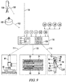
- the total station 100 generates signals corresponding to the location of the reference objects S1 and S2 within the external reference system, and those signals are communicated via communication line 105 (see Fig. 9 ) to the controller 112 of the slipform paving machine 10 as further described below.
- the communication line 105 is schematic only, and it will be understood that such communication line may include wireless communications.
- the 3D stringless reference objects S1 and S2 may be GNSS sensors which receive signals 103 from a plurality of satellites such as 102 and generate signals corresponding to the location of the reference objects S1 and S2 within the external reference system. Those signals generated by the GNSS sensors S1 and S2 are then communicated to the controller of the slipform paving machine 10 as further described below.
- the signals from the total station 100 and/or signals from GNSS sensors S1 and S2 may all be referred to as input signals corresponding to the locations of the objects S1 and S2 within the external reference system.
- the word “stringless” in the term “3D stringless reference object” means that the reference object does not engage a stringline such as the stringline 132 shown in Figs. 1 and 3 .
- a controller 112 schematically illustrated in Fig. 9 receives the input signals corresponding to the locations of the objects S1 and S2 within the external reference system, and generates control signals directed to the front and rear left side adjustable columns 44A and 44C to control a height of the objects S1 and S2 and thus of the machine frame 12 at points 104 and 106 relative to the external reference system.
- Communication of height adjustment signals from the controller 112 to the height adjustable columns 44 of the machine 10 are schematically illustrated in Fig. 9 by communication line 114.
- the height adjustable columns 44 each include a hydraulic ram (not shown) actuated by a hydraulic control valve which controls flow of hydraulic fluid to and from the opposite sides of the hydraulic ram.
- the hydraulic control valves may be controlled by electrical signals conducted over communication line 114 from controller 112 in a known manner.
- controller 112 may control the direction of the slipform paving machine 10 within the external reference system by steering of the ground engaging units 40 via their respective steering cylinders 86. Communication of such steering signals from controller 112 to the various steering cylinders 86 is schematically illustrated by communication line 116 shown in Fig. 9 . Again, electrical steering signals may be communicated over communication line 116, to electrically actuate hydraulic control valves (not shown) which direct hydraulic fluid to and from the hydraulic rams 86 in a known manner to steer each of the ground engaging units 40.
- Controller 112 includes a processor 113, a computer readable memory medium 115, a data base 117 and an input/output module or control panel 119 having a display 121.
- An input/output device 123 such as a keyboard or other user interface, is provided so that the human operator main input instructions to the controller. It is understood that the controller 112 described herein may be a single controller having all of the described functionality, or it may include multiple controllers wherein the described functionality is distributed among the multiple controllers.
- computer-readable memory medium may refer to any non-transitory medium 115 alone or as one of a plurality of non-transitory memory media 115 within which is embodied a computer program product 125 that includes processor-executable software, instructions or program modules which upon execution may provide data or otherwise cause a computer system to implement subject matter or otherwise operate in a specific manner as further defined herein. It may further be understood that more than one type of memory media may be used in combination to conduct processor-executable software, instructions or program modules from a first memory medium upon which the software, instructions or program modules initially reside to a processor for execution.
- Memory media as generally used herein may further include without limitation transmission media and/or storage media.
- Storage media may refer in an equivalent manner to volatile and non-volatile, removable and non-removable media, including at least dynamic memory, application specific integrated circuits (ASIC), chip memory devices, optical or magnetic disk memory devices, flash memory devices, or any other medium which may be used to stored data in a processor-accessible manner, and may unless otherwise stated either reside on a single computing platform or be distributed across a plurality of such platforms.
- Transmission media may include any tangible media effective to permit processor-executable software, instructions or program modules residing on the media to be read and executed by a processor, including without limitation wire, cable, fiber-optic and wireless media such as is known in the art.
- processor may refer to at least general-purpose or specific-purpose processing devices and/or logic as may be understood by one of skill in the art, including but not limited to single- or multithreading processors, central processors, parent processors, graphical processors, media processors, and the like.
- the slipform paving machine 10 further includes a width sensor S3 arranged to generate a width signal corresponding to a change in the frame width 32.
- the width sensor S3 comprises an additional 3D stringless reference object S3.
- the additional object S3 may also be a reflector or prism for such an optical based system.
- the objects S1 and S2 are GNSS sensors then the additional object S3 may also be a GNSS sensor.
- the additional object S3 is fixedly mounted on right side frame member 16 by a mast 118.
- a mixture of reference objects some being reflectors used with an optical system and some being GNSS sensors.
- a total system 100 with reflectors S1 and S2 may be used for the first side 14 of the machine 10 as seen in Fig. 1 because of the high accuracy of such a system for determining the height of the machine frame 12, and at the same time a GNSS sensor S3 may be used to determine the location of the other side 16 of the frame.
- a cross slope sensor 122 may be used to accurately control the height of the other side 16 of the frame.
- the controller 112 can determine the frame width 32, and thus the additional object S3 may be generally described as a width sensor S3 arranged to generate a width signal corresponding to a change in the frame width 32.
- the controller 112 communicates with the hydraulic rams 24, 26, 28 and 30 via communication line 120 as schematically illustrated in Fig. 9 to control the rams 24, 26, 28 and 30 so as to vary and to control the frame width 32. Controller 112 sends electrical control signals via communication line 120 to electrically actuated hydraulic valves (not shown) associated with each of the hydraulic rams 24, 26, 28 and 30, to direct hydraulic fluid to and from the rams 24, 26, 28 and 30 to control extension and retraction of the same in a known manner.
- One or more cross slope sensors 122 may also be mounted on the machine frame, and provide an input signal to controller 112 as schematically illustrated in Fig. 9 .
- the controller 112 may vary the extension of one or more of the height adjustable supports 44 to adjust the cross slope of the slipform paving machine 10 to a desired value.
- a width sensor may be provided by extension sensors 124, 126, 128 and 130 associated with the actuator rams 24, 26, 28 and 30, respectively.
- the height and location of the left side frame member 14 may be determined via reference objects S1 and S2, and the frame width 32 may be controlled via the extension sensors 124, 126, 128 and 130 and control of the extension of the rams 24, 26, 28 and 30.
- extension sensors can be physically separate from the actuator rams.
- separate extension sensors (not shown) can be connected between the main frame module 18 and each of the side frame members 14 and 16. Also there could be a single extension sensor extending between the side frame members 14 and 16.
- a stringline 132 may be fixed in the external reference system relative to the ground 134.
- the right side frame member 16 may carry a stringline sensor 136 as schematically illustrated in Figs. 1 and 3 .
- the stringline sensor 136 comprises the width sensor mounted on the machine 12, such that the stringline sensor 136 moves relative to the objects S1 and S2 when the frame width 32 is varied.
- the stringline sensor 136 may be a two-dimensional sensor, or may be used to locate the position of the right side of the slab 62 solely in the horizontal plane.
- the two 3D stringless reference objects S1 and S2 are spaced apart longitudinally by a spacing component parallel to the operating direction 32. Those objects S1 and S2 are longitudinally fixed relative to the side frame member 14.
- This arrangement is schematically illustrated in Fig. 6A . It is noted that in the schematic illustrations of Fig. 6A-6F , only the frame members 14, 16 and 18 are shown, and the swing legs 42 and ground engaging units 40 have been deleted for ease of illustration.
- the two 3D stringless reference objects S1 and S2 may be attached to the main frame module 18.
- the objects S1 and S2 are spaced apart laterally with a spacing component perpendicular to the operating direction 34.
- the objects S1 and S2 are spaced apart longitudinally.
- FIG. 3A Another embodiment is illustrated in Fig. 3A , wherein the slipform paving machine 10 includes a carrier frame 138.
- the objects S1 and S2 are fixedly attached to the carrier frame 138 so that a distance 140 between the objects S1 and S2 is fixed by the structure of the carrier frame 138.
- the carrier frame 138 is fixed relative to the main frame module 18.
- the embodiment of Fig. 3A is schematically illustrated in Fig. 6D .
- the carrier frame 138 is fixed at 142 to the left side frame member 14, and a traveling support 144 supports the carrier frame 138 from the main frame module 18 while allowing relative lateral movement between the carrier frame 138 and the main frame module 18.
- the traveling support 144 may be constructed as a rolling support using rollers or bearings.
- the traveling support 144 may be a sliding support providing a sliding bearing.
- the embodiment of Fig. 3B is schematically illustrated in Fig. 6E .
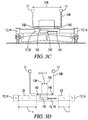
- Fig. 3C illustrates still another embodiment wherein the carrier frame 138 is adjustably positioned on the main frame module 18 on travelling supports 143 and 145.
- An adjustment device 147 is connected to the main frame module 18 at 149 and to the carrier frame 138 at 151. Adjustment device 147 controls the lateral position of carrier frame 138 on the main frame module 18. This allows the carrier frame 138 to be maintained in a central location spanning a main trajectory 154 of the machine 10 as is further described below with regards to Fig. 8A .
- the embodiment of Fig. 3C is schematically illustrated in Fig. 6F .
- the position and orientation of the frame 12 in the external reference system may be determined by information from the reference objects S1 and S2, and additional information from the width sensor in any of its embodiments described above. Also information from the cross slope sensor 122 may be utilized to further determine and control the cross slope of the frame 12.
- Figs. 6A-6F All of the embodiments described above in Figs. 6A-6F have been with reference to the double telescoping frame 12 shown in Fig. 1 . Additionally, similar control systems may be utilized with a modified slipform paving machine 10A as shown in Fig. 5 which telescopes only to the left hand side from its modified main frame module 18A.
- Figs. 7A-7F schematically illustrate various possible positioning arrangements for the 3D stringless reference objects S1 and S2 on the slipform paving machine 10A.
- the second side frame member 16 is an integral part of the main frame module 18A.
- the machine frame 12 may be described as including first and second side frame members 14 and 16.
- the machine frame may be described as including the main frame module 18A and having one side member 14 laterally movable relative to the main frame module.
- the machine frame may be described as including the main frame module 18 and having both of the side frame members 14 and 16 laterally movable relative to the main frame module. All of the embodiments may be described as having at least one of the side frame members laterally movable relative to the main frame module.
- the reference objects S1 and S2 are fixed to the left side frame member 14 and are longitudinally spaced apart.
- the reference objects S1 and S2 are fixed to the main frame module 18A and are transversely spaced apart.
- the reference objects S1 and S2 are fixed on the main frame module 18A and are longitudinally spaced apart.
- the reference objects S1 and S2 are mounted on carrier frame 138 which is fixed to the main frame module 18A.
- the reference objects S1 and S2 are fixed to the carrier frame 138 which is fixed to the left side frame member 14 and which is slidingly supported from the main frame module 18A by a traveling support similar to support 144 illustrated in Fig. 3B .
- the reference objects S1 and S2 are fixed to the carrier frame 138 which is adjustable in lateral position on the main frame module 18 via travelling supports 143 and 145 and adjustment device 147.
- the distance between the two 3D stringless reference objects S1 and S2 is fixed.
- Such arrangements are compatible with commercially available GNSS and total station based guidance systems which are configured to determine the location and orientation of an object, such as machine 10, within an external reference system based upon the locations of two points having a fixed spacing. Also from the known geometry of the machine 10, the location of those two points determines the location of all other points on the machine 10 within the external reference system.
- Fig. 10 is a schematic plan view similar to Fig. 6A , but illustrating a dual telescoping machine frame which has the two 3D stringless reference objects S1 and S2 mounted on the machine frame such that a distance 156 between the objects S1 and S2 is variable.
- the controller 112 of Fig. 9 will include a controller module 158 as part of the computer program 125.
- the controller module 158 is configured to detect the variable distance 156 between the two reference objects S1 and S2 based upon the input signals corresponding to the positions of the two 3D stringless reference objects S1 and S2 in the external reference system.
- the controller module 158 provides the width sensor configured to generate a width signal corresponding to a change in frame width or paving width.
- the controller module 158 in addition to determining the variable distance 156 between reference objects S1 and S2, must be compatible with the overall guidance system which determines the position of all of the points on the machine 10 within the external reference system based upon the locations of S1 and S2 and the variable distance 156 between those locations.
- one reference object S1 is fixed relative to the laterally movable first side frame member 14 and the other reference object S2 is fixed relative to the laterally movable second side frame member 16.
- one reference object S1 is fixed relative to laterally movable first side frame member 14 and the other reference object S2 is fixed relative to the main frame module 18A.
- Embodiments like those of Fig. 10 and Fig. 11 can simplify the overall arrangement of reference objects and width sensors because the two variably spaced reference objects S1 and S2 can provide the dual function of both determining the location and height and direction of the machine 10 in the external reference system, and sensing the variable spacing of the objects S1 and S2 corresponding to changes in frame width and paving width. This may eliminate the need for a third sensor S3, also referred to as a width sensor.
- the additional width sensor S3 can provide a way to confirm the distance variations detected between the reference objects S1 and S2.
- a method of operating a slipform paving machine 10 which permits the slipform paving machine 10 to move forward in the operating direction 34 and to mold the concrete 68 into a concrete slab structure 62 extending between the ground engaging units 40 and behind the concrete mold 52, 54.
- the width of the concrete slab structure 62 may be varied on the fly as the paving machine moves forward.
- a human operator of the machine 10 may input to the controller 112 a desired or preset three dimensional path for the machine 10 within the external reference system.
- the path will correspond to a desired elevation, direction, cross slope and width of the concrete structure to be molded by the paving machine 10.
- the path may include a variable width for the concrete slab structure.
- the controller 112 can determine any deviation of the machine 10 from the desired path and the controller 112 can control the steering, height, cross slope and paving width of the machine 10 so that the actual path of the machine corresponds to the preset path.
- a primarily guidance for the slipform paving machine 10 can be provided by sensing a location in the external reference system (either the optical based system 100 or satellite based system 102) of the 3D stringless reference objects S1 and S2, each of which is fixed relative to at least one of the main frame module 18 and one of the laterally extendable side frame members 14 and/or 16.
- the height and direction of the machine frame 12 within the external reference system may be controlled by the controller 112 in response to signals corresponding to the positions of the reference objects S1 and S2.
- both of the reference objects S1 and S2 will be fixed relative to the same one of the main frame module 18 or one of the laterally extendable side frame members 14 or 16.
- each of the reference objects S1 and S2 will be fixed relative to a different one of the main frame module 18 or one of the laterally extendable side frame members 14 or 16.
- the frame width 32 may be adjusted on the fly to thereby adjust the mold width 78 and similarly adjust a slab width 146 of the concrete slab 62 as schematically illustrated in Figs. 8A, 8B and 8C .
- the mold width may be adjusted independently of the frame width. These adjustments may be automatically made by controller 112 in response to width signals from reference object S3, or from other width sensors described herein, and in accordance with the predetermined path which has been input into the controller 112.
- the cross slope may also be adjusted. This adjustment may be automatically made by controller 112 in response to cross slope signals from sensor 122 and in accordance with the predetermined path which has been input into the controller 112.
- Fig. 8A schematically illustrates a slab 62 having a first slab width 146 and a second slab width 148.
- the actuators 24, 26, 28 and 30 are actuated to continuously adjust the frame width 32 and thus the mold width 78 as the mold 52, 54 moves through a transition distance 150 thus forming a continuous transition 152 in the concrete slab structure 62 from the first slab width 146 to the second slab width 148.
- the slab width is symmetrically extended on both sides of a main trajectory line 154 of the paving machine 10.
- the slab width is extended asymmetrically to one side of the main trajectory 154.
- the slab width is extended asymmetrically to both sides of the main trajectory 154.
- the slab width may be decreased as the paving machine 10 moves forward in a manner analogous to any of Figs. 8A-8C .
- Fig. 3C it may be desirable to maintain the carrier frame 138 position so as to equally span the main trajectory 154, even if there is an asymmetric telescoping of the frame 12. This is accommodated by the variable positioned carrier frame 138 of Fig. 3C as is schematically illustrated in Fig. 3D .
- Fig. 3D schematically illustrates the frame arrangement of Fig. 3C in an asymmetric telescoping mode relative to the main trajectory 154 of the concrete slab schematically illustrated in Fig. 8A .
- the left side frame member 14 has been extended relative to main frame module 18 by a distance "a”
- the right side frame member 16 has been extended relative to main frame module 18 by a lesser distance "b”.
- the adjustment device 147 shifts a center line 139 of the carrier frame 138 to the left relative to a center line 141 of the main frame module 18 by the distance (a-b)/2.
Landscapes
- Engineering & Computer Science (AREA)
- Structural Engineering (AREA)
- Architecture (AREA)
- Civil Engineering (AREA)
- Physics & Mathematics (AREA)
- Mechanical Engineering (AREA)
- Transportation (AREA)
- Combustion & Propulsion (AREA)
- Chemical & Material Sciences (AREA)
- General Physics & Mathematics (AREA)
- Radar, Positioning & Navigation (AREA)
- Remote Sensing (AREA)
- Theoretical Computer Science (AREA)
- Computer Vision & Pattern Recognition (AREA)
- Multimedia (AREA)
- Aviation & Aerospace Engineering (AREA)
- Automation & Control Theory (AREA)
- Geometry (AREA)
- Road Paving Machines (AREA)
Priority Applications (1)
| Application Number | Priority Date | Filing Date | Title |
|---|---|---|---|
| EP18172601.9A EP3406794B1 (fr) | 2014-12-19 | 2015-12-18 | Finisseur à coffrage glissant |
Applications Claiming Priority (1)
| Application Number | Priority Date | Filing Date | Title |
|---|---|---|---|
| US14/576,399 US9551115B2 (en) | 2014-12-19 | 2014-12-19 | Transition on the fly |
Related Child Applications (1)
| Application Number | Title | Priority Date | Filing Date |
|---|---|---|---|
| EP18172601.9A Division EP3406794B1 (fr) | 2014-12-19 | 2015-12-18 | Finisseur à coffrage glissant |
Publications (2)
| Publication Number | Publication Date |
|---|---|
| EP3034698A1 true EP3034698A1 (fr) | 2016-06-22 |
| EP3034698B1 EP3034698B1 (fr) | 2018-06-13 |
Family
ID=55069689
Family Applications (2)
| Application Number | Title | Priority Date | Filing Date |
|---|---|---|---|
| EP18172601.9A Active EP3406794B1 (fr) | 2014-12-19 | 2015-12-18 | Finisseur à coffrage glissant |
| EP15201078.1A Active EP3034698B1 (fr) | 2014-12-19 | 2015-12-18 | Finisseur à coffrage glissant et procédé d'exploitation d'un finisseur à coffrage glissant |
Family Applications Before (1)
| Application Number | Title | Priority Date | Filing Date |
|---|---|---|---|
| EP18172601.9A Active EP3406794B1 (fr) | 2014-12-19 | 2015-12-18 | Finisseur à coffrage glissant |
Country Status (3)
| Country | Link |
|---|---|
| US (3) | US9551115B2 (fr) |
| EP (2) | EP3406794B1 (fr) |
| CN (2) | CN205329491U (fr) |
Cited By (4)
| Publication number | Priority date | Publication date | Assignee | Title |
|---|---|---|---|---|
| WO2020086597A1 (fr) * | 2018-10-23 | 2020-04-30 | Caterpillar Paving Products Inc. | Fraiseuse routière à commande d'inclinaison de bâti et procédé pour une telle commande |
| CN112853886A (zh) * | 2021-01-18 | 2021-05-28 | 盛建芳 | 一种无拖痕艺术混凝土路面铺料装置 |
| CN113032860A (zh) * | 2019-12-07 | 2021-06-25 | 黄慧 | 铺路材料剂量调配平台及方法 |
| CH717191A1 (de) * | 2020-03-04 | 2021-09-15 | Kibag Bauleistungen Ag | Vorrichtung zum Einbau von Gussasphalt auf einem Fahrbahnuntergrund und Verfahren zur Fertigung einer Asphaltfahrbahn. |
Families Citing this family (42)
| Publication number | Priority date | Publication date | Assignee | Title |
|---|---|---|---|---|
| US9908571B2 (en) * | 2010-03-26 | 2018-03-06 | Guntert & Zimmerman Const. Div., Inc. | Adjustable bolster swing legs for slipform paving machines |
| EP2858471B1 (fr) * | 2013-03-20 | 2016-06-01 | Couchman, Johnny | Véhicule agricole autonome |
| US9869066B2 (en) | 2013-11-27 | 2018-01-16 | Howard Cooper | System and method for slip forming concrete barriers |
| CN106164375A (zh) * | 2014-02-21 | 2016-11-23 | 卡斯特斯弗朗索瓦咨询私人有限公司 | 用于铺路的机器 |
| US9663162B1 (en) * | 2014-02-28 | 2017-05-30 | Gomaco Corporation | Hydraulic pivot arm positioning assembly |
| US9764762B2 (en) * | 2014-05-13 | 2017-09-19 | Gomaco Corporation | Rotary pivot arm positioning assembly |
| US9388537B2 (en) * | 2014-06-09 | 2016-07-12 | Wirtgen Gmbh | Swing over steering |
| US9388538B2 (en) * | 2014-06-09 | 2016-07-12 | Wirtgen Gmbh | Frame width adjustment by steering |
| US9739019B1 (en) * | 2014-06-13 | 2017-08-22 | Gomaco Corporation | Bridge paving device |
| US9631329B2 (en) | 2014-12-19 | 2017-04-25 | Wirtgen Gmbh | Frame distortion control |
| US9551115B2 (en) * | 2014-12-19 | 2017-01-24 | Wirtgen Gmbh | Transition on the fly |
| US10653052B2 (en) * | 2015-03-16 | 2020-05-19 | Tynab Pty Ltd | Wheel track renovator and method of use |
| US10132046B2 (en) * | 2015-04-20 | 2018-11-20 | Wirtgen Gmbh | Concrete texturing machine |
| EP3208381B1 (fr) * | 2016-02-17 | 2018-10-10 | Caterpillar Paving Products Inc. | Machine de pavage pour appliquer différents profils de couronne et son procédé |
| US10206016B1 (en) * | 2016-02-19 | 2019-02-12 | Gomaco Corporation | Streaming smoothness indicator system |
| EP3276079B1 (fr) * | 2016-07-26 | 2021-07-14 | Caterpillar Paving Products Inc. | Système de commande pour un finisseur |
| US9969427B1 (en) * | 2016-11-16 | 2018-05-15 | Wirtgen Gmbh | Transport conversion mode |
| US10253461B2 (en) * | 2016-12-07 | 2019-04-09 | Wirtgen Gmbh | Variable width automatic transition |
| DE102017012010A1 (de) * | 2017-12-22 | 2019-06-27 | Wirtgen Gmbh | Selbstfahrende Baumaschine und Verfahren zum Steuern einer selbstfahrenden Baumaschine |
| WO2019133915A1 (fr) * | 2017-12-29 | 2019-07-04 | Guntert & Zimmerman Const. Div., Inc. | Dispositif d'insertion de barre de cheville à largeur étendue |
| US10961669B2 (en) | 2018-01-12 | 2021-03-30 | Terex Usa, Llc | System and method for changing a surface characteristic of a concrete bridge surface |
| US11008714B2 (en) | 2018-04-09 | 2021-05-18 | Howard Cooper | Slip forming structures using multiple molds |
| WO2019200376A1 (fr) * | 2018-04-13 | 2019-10-17 | Gomaco Corporation | Dispositif de finition de pont tridimensionnel |
| US10472780B1 (en) | 2018-06-15 | 2019-11-12 | Wirtgen Gmbh | Shiftable mold |
| US11243531B2 (en) | 2018-08-09 | 2022-02-08 | Caterpillar Paving Products Inc. | Navigation system for a machine |
| US11105048B2 (en) * | 2018-10-17 | 2021-08-31 | Caterpillar Paving Products Inc. | Screed dual carriage extender tube orientation |
| US11555278B2 (en) | 2019-07-08 | 2023-01-17 | Caterpillar Paving Products Inc. | Autowidth input for paving operations |
| EP3851584B1 (fr) * | 2020-01-16 | 2022-11-09 | Joseph Vögele AG | Finisseuse de route pourvue de commande de compression |
| CN112549275B (zh) * | 2020-12-02 | 2022-07-15 | 德州海天机电科技有限公司 | 一种预应力长线台混凝土预制件布料机控制系统 |
| US12252850B2 (en) | 2021-01-29 | 2025-03-18 | Gomaco Corporation | Slew drive control |
| US11149388B1 (en) | 2021-01-29 | 2021-10-19 | Gomaco Corporation | Slew drive control |
| US12209384B2 (en) | 2021-09-20 | 2025-01-28 | Deere &Company | Laser reference tracking and target corrections for work machines |
| US12203226B2 (en) | 2021-12-20 | 2025-01-21 | Wirtgen Gmbh | Dowel bar inserter |
| DE102021134452B4 (de) * | 2021-12-23 | 2024-02-22 | Wirtgen Gmbh | Gleitschalungsfertiger |
| US12516480B2 (en) * | 2022-03-22 | 2026-01-06 | Wirtgen Gmbh | Slipform paver with suspended adjustable width mold |
| US12571170B2 (en) * | 2022-04-21 | 2026-03-10 | Wirtgen Gmbh | Differential milling and paving |
| US12601122B2 (en) | 2022-12-14 | 2026-04-14 | Wirtgen Gmbh | Adjustable string line sensors for slip form paving |
| US12473698B2 (en) | 2022-12-14 | 2025-11-18 | Wirtgen Gmbh | Roll control during slip form paving |
| US12553196B2 (en) | 2022-12-14 | 2026-02-17 | Wirtgen Gmbh | Measuring paving thickness during slip form paving |
| US12291840B2 (en) | 2023-01-25 | 2025-05-06 | Deere &Company | System and method of automated setting of elevation reference for continuous grade control |
| US12584277B2 (en) | 2023-08-04 | 2026-03-24 | Wirtgen Gmbh | Constant surface patterns during slip form paving |
| US12590423B2 (en) | 2023-08-04 | 2026-03-31 | Wirtgen Gmbh | Edge slump control |
Citations (2)
| Publication number | Priority date | Publication date | Assignee | Title |
|---|---|---|---|---|
| DE19814052A1 (de) * | 1998-03-30 | 1999-10-14 | Wirtgen Gmbh | Gleitschalungsfertiger |
| EP2006448A1 (fr) * | 2007-06-21 | 2008-12-24 | Leica Geosystems AG | Train de finisseuses pour la fabrication d'une couche de revêtement routier en béton ou en asphalte |
Family Cites Families (28)
| Publication number | Priority date | Publication date | Assignee | Title |
|---|---|---|---|---|
| US3970405A (en) * | 1974-05-03 | 1976-07-20 | Cmi Corporation | Slipform paving apparatus |
| US4900186A (en) * | 1988-10-31 | 1990-02-13 | Swisher Jr George W | Three-track zero clearance paver |
| DE4420016A1 (de) * | 1994-06-08 | 1995-12-14 | Dynapac Gmbh | Einbaubohle für einen Straßendeckenfertiger |
| US5615972A (en) * | 1995-07-20 | 1997-04-01 | Guntert & Zimmerman Construction Div., Inc. | Paving machine with extended telescoping members |
| US5941658A (en) * | 1997-06-02 | 1999-08-24 | Guntert & Zimmerman Constr. Div. Inc. | Cross-slope level control for mobile machinery |
| DE19814053B4 (de) | 1998-03-30 | 2007-07-26 | Wirtgen Gmbh | Vorrichtung zum Abfräsen von Bodenflächen, insbesondere Fahrbahnen |
| DE29918747U1 (de) | 1999-10-25 | 2000-02-24 | MOBA - Mobile Automation GmbH, 65604 Elz | Vorrichtung zum Steuern eines Straßenfertigers |
| DE50008220D1 (de) | 2000-01-19 | 2004-11-18 | Joseph Voegele Ag | Verfahren zum Steuern einer Baumaschine bzw. eines Strassenfertigers und Strassenfertiger |
| US6582152B2 (en) * | 2000-05-11 | 2003-06-24 | Leone Construction Company | Zero clearance variable width concrete paving machine |
| US6954999B1 (en) | 2004-12-13 | 2005-10-18 | Trimble Navigation Limited | Trencher guidance via GPS |
| US20060198700A1 (en) | 2005-03-04 | 2006-09-07 | Jurgen Maier | Method and system for controlling construction machine |
| CN2934337Y (zh) * | 2006-06-15 | 2007-08-15 | 陕西中大机械集团有限责任公司 | 摊铺机机械加宽式熨平板液压调宽装置 |
| US8131462B2 (en) | 2008-02-28 | 2012-03-06 | Leica Geosystems Ag | Vehicle guidance and sensor bias determination |
| DE102009059106A1 (de) * | 2009-12-18 | 2011-06-22 | Wirtgen GmbH, 53578 | Selbstfahrende Baumaschine und Verfahren zur Steuerung einer selbstfahrenden Baumaschine |
| DE102012001289A1 (de) * | 2012-01-25 | 2013-07-25 | Wirtgen Gmbh | Selbstfahrende Baumaschine und Verfahren zum Steuern einer selbstfahrenden Baumaschine |
| CN103374872A (zh) * | 2012-04-21 | 2013-10-30 | 韩志强 | 一种起拱式且幅宽可任意调整的水泥混凝土摊铺机 |
| US9279679B2 (en) | 2012-09-12 | 2016-03-08 | Kabushiki Kaisha Topcon | Construction machine control method and construction machine control system |
| US8788154B2 (en) | 2012-09-12 | 2014-07-22 | Kabushiki Kaisha Topcon | Construction machine control method and construction machine control system |
| EP2789739A1 (fr) * | 2013-04-10 | 2014-10-15 | Leica Geosystems AG | Kit de contrôle d'alignement de piste automatique et procédé d'alignement de piste automatisé |
| DE102013216950A1 (de) * | 2013-08-26 | 2015-02-26 | Wirtgen Gmbh | Gleitschalungsfertiger, sowie Verfahren zur Anpassung der Breite einer Muldeneinrichtung |
| DE102014209880A1 (de) * | 2014-05-23 | 2015-11-26 | Wirtgen Gmbh | Nachbehandlungsmaschine sowie Verfahren zum nachträglichen Bearbeiten einer frisch gefertigten Betonschicht |
| US9388538B2 (en) * | 2014-06-09 | 2016-07-12 | Wirtgen Gmbh | Frame width adjustment by steering |
| US9388537B2 (en) * | 2014-06-09 | 2016-07-12 | Wirtgen Gmbh | Swing over steering |
| US9388539B2 (en) * | 2014-06-09 | 2016-07-12 | Wirtgen Gmbh | Selective clamping of chassis |
| US9684308B2 (en) * | 2014-11-13 | 2017-06-20 | Wirtgen Gmbh | Transport mode conversion |
| US9631329B2 (en) * | 2014-12-19 | 2017-04-25 | Wirtgen Gmbh | Frame distortion control |
| US9551115B2 (en) * | 2014-12-19 | 2017-01-24 | Wirtgen Gmbh | Transition on the fly |
| US10132046B2 (en) * | 2015-04-20 | 2018-11-20 | Wirtgen Gmbh | Concrete texturing machine |
-
2014
- 2014-12-19 US US14/576,399 patent/US9551115B2/en active Active
-
2015
- 2015-12-18 EP EP18172601.9A patent/EP3406794B1/fr active Active
- 2015-12-18 EP EP15201078.1A patent/EP3034698B1/fr active Active
- 2015-12-21 CN CN201521072140.6U patent/CN205329491U/zh not_active Withdrawn - After Issue
- 2015-12-21 CN CN201510965239.7A patent/CN105714656B/zh active Active
-
2016
- 2016-12-21 US US15/386,909 patent/US9797099B2/en active Active
-
2017
- 2017-10-09 US US15/728,011 patent/US10161088B2/en active Active
Patent Citations (2)
| Publication number | Priority date | Publication date | Assignee | Title |
|---|---|---|---|---|
| DE19814052A1 (de) * | 1998-03-30 | 1999-10-14 | Wirtgen Gmbh | Gleitschalungsfertiger |
| EP2006448A1 (fr) * | 2007-06-21 | 2008-12-24 | Leica Geosystems AG | Train de finisseuses pour la fabrication d'une couche de revêtement routier en béton ou en asphalte |
Cited By (6)
| Publication number | Priority date | Publication date | Assignee | Title |
|---|---|---|---|---|
| WO2020086597A1 (fr) * | 2018-10-23 | 2020-04-30 | Caterpillar Paving Products Inc. | Fraiseuse routière à commande d'inclinaison de bâti et procédé pour une telle commande |
| US11679639B2 (en) | 2018-10-23 | 2023-06-20 | Caterpillar Paving Products Inc. | Systems and methods for controlling ground inclination of rotary cutting machines |
| CN113032860A (zh) * | 2019-12-07 | 2021-06-25 | 黄慧 | 铺路材料剂量调配平台及方法 |
| CN113032860B (zh) * | 2019-12-07 | 2022-12-27 | 中交二公局城市建设发展有限公司 | 铺路材料剂量调配平台及方法 |
| CH717191A1 (de) * | 2020-03-04 | 2021-09-15 | Kibag Bauleistungen Ag | Vorrichtung zum Einbau von Gussasphalt auf einem Fahrbahnuntergrund und Verfahren zur Fertigung einer Asphaltfahrbahn. |
| CN112853886A (zh) * | 2021-01-18 | 2021-05-28 | 盛建芳 | 一种无拖痕艺术混凝土路面铺料装置 |
Also Published As
| Publication number | Publication date |
|---|---|
| US9797099B2 (en) | 2017-10-24 |
| EP3034698B1 (fr) | 2018-06-13 |
| US20170159249A1 (en) | 2017-06-08 |
| EP3406794B1 (fr) | 2020-11-18 |
| CN205329491U (zh) | 2016-06-22 |
| US20160177517A1 (en) | 2016-06-23 |
| US20180094391A1 (en) | 2018-04-05 |
| EP3406794A1 (fr) | 2018-11-28 |
| CN105714656A (zh) | 2016-06-29 |
| CN105714656B (zh) | 2018-01-23 |
| US9551115B2 (en) | 2017-01-24 |
| US10161088B2 (en) | 2018-12-25 |
Similar Documents
| Publication | Publication Date | Title |
|---|---|---|
| EP3406794B1 (fr) | Finisseur à coffrage glissant | |
| EP3333318B1 (fr) | Une machine à coffrage glissant avec transition à largeur variable automatique | |
| EP3034697B1 (fr) | Machine de construction et procédé de fonctionnement d'une machine de construction | |
| US10221528B2 (en) | Swing over steering | |
| US20190330807A1 (en) | Roadway marker control system | |
| EP1118713B1 (fr) | Procédé de commande d'une machine de chantier ou finisseuse et finisseuse | |
| EP3674483B1 (fr) | Finisseur à coffrages glissants | |
| US10994775B2 (en) | System and method for controlling dollies | |
| CN103225251A (zh) | 自推进工程机械和控制工程机械的方法 | |
| US9279235B1 (en) | Implement position control system having automatic calibration | |
| JP4212627B2 (ja) | 舗装材敷均装置及び舗装材敷均方法、並びに、締固装置及び舗装路面締固方法 | |
| CN118326780A (zh) | 滑模摊铺机在步进式滑模施工过程中的位姿控制方法及系统 |
Legal Events
| Date | Code | Title | Description |
|---|---|---|---|
| PUAI | Public reference made under article 153(3) epc to a published international application that has entered the european phase |
Free format text: ORIGINAL CODE: 0009012 |
|
| AK | Designated contracting states |
Kind code of ref document: A1 Designated state(s): AL AT BE BG CH CY CZ DE DK EE ES FI FR GB GR HR HU IE IS IT LI LT LU LV MC MK MT NL NO PL PT RO RS SE SI SK SM TR |
|
| AX | Request for extension of the european patent |
Extension state: BA ME |
|
| STAA | Information on the status of an ep patent application or granted ep patent |
Free format text: STATUS: REQUEST FOR EXAMINATION WAS MADE |
|
| 17P | Request for examination filed |
Effective date: 20161213 |
|
| RBV | Designated contracting states (corrected) |
Designated state(s): AL AT BE BG CH CY CZ DE DK EE ES FI FR GB GR HR HU IE IS IT LI LT LU LV MC MK MT NL NO PL PT RO RS SE SI SK SM TR |
|
| STAA | Information on the status of an ep patent application or granted ep patent |
Free format text: STATUS: EXAMINATION IS IN PROGRESS |
|
| 17Q | First examination report despatched |
Effective date: 20170621 |
|
| GRAP | Despatch of communication of intention to grant a patent |
Free format text: ORIGINAL CODE: EPIDOSNIGR1 |
|
| STAA | Information on the status of an ep patent application or granted ep patent |
Free format text: STATUS: GRANT OF PATENT IS INTENDED |
|
| INTG | Intention to grant announced |
Effective date: 20180124 |
|
| GRAS | Grant fee paid |
Free format text: ORIGINAL CODE: EPIDOSNIGR3 |
|
| GRAA | (expected) grant |
Free format text: ORIGINAL CODE: 0009210 |
|
| STAA | Information on the status of an ep patent application or granted ep patent |
Free format text: STATUS: THE PATENT HAS BEEN GRANTED |
|
| AK | Designated contracting states |
Kind code of ref document: B1 Designated state(s): AL AT BE BG CH CY CZ DE DK EE ES FI FR GB GR HR HU IE IS IT LI LT LU LV MC MK MT NL NO PL PT RO RS SE SI SK SM TR |
|
| REG | Reference to a national code |
Ref country code: GB Ref legal event code: FG4D |
|
| REG | Reference to a national code |
Ref country code: CH Ref legal event code: EP Ref country code: AT Ref legal event code: REF Ref document number: 1008653 Country of ref document: AT Kind code of ref document: T Effective date: 20180615 |
|
| REG | Reference to a national code |
Ref country code: IE Ref legal event code: FG4D |
|
| REG | Reference to a national code |
Ref country code: DE Ref legal event code: R096 Ref document number: 602015012191 Country of ref document: DE |
|
| REG | Reference to a national code |
Ref country code: SE Ref legal event code: TRGR |
|
| REG | Reference to a national code |
Ref country code: NL Ref legal event code: MP Effective date: 20180613 |
|
| REG | Reference to a national code |
Ref country code: LT Ref legal event code: MG4D |
|
| PG25 | Lapsed in a contracting state [announced via postgrant information from national office to epo] |
Ref country code: FI Free format text: LAPSE BECAUSE OF FAILURE TO SUBMIT A TRANSLATION OF THE DESCRIPTION OR TO PAY THE FEE WITHIN THE PRESCRIBED TIME-LIMIT Effective date: 20180613 Ref country code: NO Free format text: LAPSE BECAUSE OF FAILURE TO SUBMIT A TRANSLATION OF THE DESCRIPTION OR TO PAY THE FEE WITHIN THE PRESCRIBED TIME-LIMIT Effective date: 20180913 Ref country code: CY Free format text: LAPSE BECAUSE OF FAILURE TO SUBMIT A TRANSLATION OF THE DESCRIPTION OR TO PAY THE FEE WITHIN THE PRESCRIBED TIME-LIMIT Effective date: 20180613 Ref country code: BG Free format text: LAPSE BECAUSE OF FAILURE TO SUBMIT A TRANSLATION OF THE DESCRIPTION OR TO PAY THE FEE WITHIN THE PRESCRIBED TIME-LIMIT Effective date: 20180913 Ref country code: LT Free format text: LAPSE BECAUSE OF FAILURE TO SUBMIT A TRANSLATION OF THE DESCRIPTION OR TO PAY THE FEE WITHIN THE PRESCRIBED TIME-LIMIT Effective date: 20180613 Ref country code: ES Free format text: LAPSE BECAUSE OF FAILURE TO SUBMIT A TRANSLATION OF THE DESCRIPTION OR TO PAY THE FEE WITHIN THE PRESCRIBED TIME-LIMIT Effective date: 20180613 |
|
| PG25 | Lapsed in a contracting state [announced via postgrant information from national office to epo] |
Ref country code: RS Free format text: LAPSE BECAUSE OF FAILURE TO SUBMIT A TRANSLATION OF THE DESCRIPTION OR TO PAY THE FEE WITHIN THE PRESCRIBED TIME-LIMIT Effective date: 20180613 Ref country code: LV Free format text: LAPSE BECAUSE OF FAILURE TO SUBMIT A TRANSLATION OF THE DESCRIPTION OR TO PAY THE FEE WITHIN THE PRESCRIBED TIME-LIMIT Effective date: 20180613 Ref country code: GR Free format text: LAPSE BECAUSE OF FAILURE TO SUBMIT A TRANSLATION OF THE DESCRIPTION OR TO PAY THE FEE WITHIN THE PRESCRIBED TIME-LIMIT Effective date: 20180914 Ref country code: HR Free format text: LAPSE BECAUSE OF FAILURE TO SUBMIT A TRANSLATION OF THE DESCRIPTION OR TO PAY THE FEE WITHIN THE PRESCRIBED TIME-LIMIT Effective date: 20180613 |
|
| REG | Reference to a national code |
Ref country code: AT Ref legal event code: MK05 Ref document number: 1008653 Country of ref document: AT Kind code of ref document: T Effective date: 20180613 |
|
| PG25 | Lapsed in a contracting state [announced via postgrant information from national office to epo] |
Ref country code: NL Free format text: LAPSE BECAUSE OF FAILURE TO SUBMIT A TRANSLATION OF THE DESCRIPTION OR TO PAY THE FEE WITHIN THE PRESCRIBED TIME-LIMIT Effective date: 20180613 |
|
| PG25 | Lapsed in a contracting state [announced via postgrant information from national office to epo] |
Ref country code: PL Free format text: LAPSE BECAUSE OF FAILURE TO SUBMIT A TRANSLATION OF THE DESCRIPTION OR TO PAY THE FEE WITHIN THE PRESCRIBED TIME-LIMIT Effective date: 20180613 Ref country code: IS Free format text: LAPSE BECAUSE OF FAILURE TO SUBMIT A TRANSLATION OF THE DESCRIPTION OR TO PAY THE FEE WITHIN THE PRESCRIBED TIME-LIMIT Effective date: 20181013 Ref country code: AT Free format text: LAPSE BECAUSE OF FAILURE TO SUBMIT A TRANSLATION OF THE DESCRIPTION OR TO PAY THE FEE WITHIN THE PRESCRIBED TIME-LIMIT Effective date: 20180613 Ref country code: EE Free format text: LAPSE BECAUSE OF FAILURE TO SUBMIT A TRANSLATION OF THE DESCRIPTION OR TO PAY THE FEE WITHIN THE PRESCRIBED TIME-LIMIT Effective date: 20180613 Ref country code: RO Free format text: LAPSE BECAUSE OF FAILURE TO SUBMIT A TRANSLATION OF THE DESCRIPTION OR TO PAY THE FEE WITHIN THE PRESCRIBED TIME-LIMIT Effective date: 20180613 Ref country code: CZ Free format text: LAPSE BECAUSE OF FAILURE TO SUBMIT A TRANSLATION OF THE DESCRIPTION OR TO PAY THE FEE WITHIN THE PRESCRIBED TIME-LIMIT Effective date: 20180613 Ref country code: SK Free format text: LAPSE BECAUSE OF FAILURE TO SUBMIT A TRANSLATION OF THE DESCRIPTION OR TO PAY THE FEE WITHIN THE PRESCRIBED TIME-LIMIT Effective date: 20180613 |
|
| PG25 | Lapsed in a contracting state [announced via postgrant information from national office to epo] |
Ref country code: SM Free format text: LAPSE BECAUSE OF FAILURE TO SUBMIT A TRANSLATION OF THE DESCRIPTION OR TO PAY THE FEE WITHIN THE PRESCRIBED TIME-LIMIT Effective date: 20180613 |
|
| REG | Reference to a national code |
Ref country code: DE Ref legal event code: R097 Ref document number: 602015012191 Country of ref document: DE |
|
| PLBE | No opposition filed within time limit |
Free format text: ORIGINAL CODE: 0009261 |
|
| STAA | Information on the status of an ep patent application or granted ep patent |
Free format text: STATUS: NO OPPOSITION FILED WITHIN TIME LIMIT |
|
| 26N | No opposition filed |
Effective date: 20190314 |
|
| PG25 | Lapsed in a contracting state [announced via postgrant information from national office to epo] |
Ref country code: SI Free format text: LAPSE BECAUSE OF FAILURE TO SUBMIT A TRANSLATION OF THE DESCRIPTION OR TO PAY THE FEE WITHIN THE PRESCRIBED TIME-LIMIT Effective date: 20180613 Ref country code: DK Free format text: LAPSE BECAUSE OF FAILURE TO SUBMIT A TRANSLATION OF THE DESCRIPTION OR TO PAY THE FEE WITHIN THE PRESCRIBED TIME-LIMIT Effective date: 20180613 |
|
| REG | Reference to a national code |
Ref country code: CH Ref legal event code: PL |
|
| PG25 | Lapsed in a contracting state [announced via postgrant information from national office to epo] |
Ref country code: MC Free format text: LAPSE BECAUSE OF FAILURE TO SUBMIT A TRANSLATION OF THE DESCRIPTION OR TO PAY THE FEE WITHIN THE PRESCRIBED TIME-LIMIT Effective date: 20180613 Ref country code: LU Free format text: LAPSE BECAUSE OF NON-PAYMENT OF DUE FEES Effective date: 20181218 |
|
| REG | Reference to a national code |
Ref country code: IE Ref legal event code: MM4A |
|
| REG | Reference to a national code |
Ref country code: BE Ref legal event code: MM Effective date: 20181231 |
|
| PG25 | Lapsed in a contracting state [announced via postgrant information from national office to epo] |
Ref country code: IE Free format text: LAPSE BECAUSE OF NON-PAYMENT OF DUE FEES Effective date: 20181218 |
|
| PG25 | Lapsed in a contracting state [announced via postgrant information from national office to epo] |
Ref country code: AL Free format text: LAPSE BECAUSE OF FAILURE TO SUBMIT A TRANSLATION OF THE DESCRIPTION OR TO PAY THE FEE WITHIN THE PRESCRIBED TIME-LIMIT Effective date: 20180613 Ref country code: BE Free format text: LAPSE BECAUSE OF NON-PAYMENT OF DUE FEES Effective date: 20181231 |
|
| PG25 | Lapsed in a contracting state [announced via postgrant information from national office to epo] |
Ref country code: CH Free format text: LAPSE BECAUSE OF NON-PAYMENT OF DUE FEES Effective date: 20181231 Ref country code: LI Free format text: LAPSE BECAUSE OF NON-PAYMENT OF DUE FEES Effective date: 20181231 |
|
| PG25 | Lapsed in a contracting state [announced via postgrant information from national office to epo] |
Ref country code: MT Free format text: LAPSE BECAUSE OF NON-PAYMENT OF DUE FEES Effective date: 20181218 |
|
| PG25 | Lapsed in a contracting state [announced via postgrant information from national office to epo] |
Ref country code: TR Free format text: LAPSE BECAUSE OF FAILURE TO SUBMIT A TRANSLATION OF THE DESCRIPTION OR TO PAY THE FEE WITHIN THE PRESCRIBED TIME-LIMIT Effective date: 20180613 |
|
| PG25 | Lapsed in a contracting state [announced via postgrant information from national office to epo] |
Ref country code: PT Free format text: LAPSE BECAUSE OF FAILURE TO SUBMIT A TRANSLATION OF THE DESCRIPTION OR TO PAY THE FEE WITHIN THE PRESCRIBED TIME-LIMIT Effective date: 20180613 |
|
| PG25 | Lapsed in a contracting state [announced via postgrant information from national office to epo] |
Ref country code: MK Free format text: LAPSE BECAUSE OF NON-PAYMENT OF DUE FEES Effective date: 20180613 Ref country code: HU Free format text: LAPSE BECAUSE OF FAILURE TO SUBMIT A TRANSLATION OF THE DESCRIPTION OR TO PAY THE FEE WITHIN THE PRESCRIBED TIME-LIMIT; INVALID AB INITIO Effective date: 20151218 |
|
| P01 | Opt-out of the competence of the unified patent court (upc) registered |
Effective date: 20230525 |
|
| PGFP | Annual fee paid to national office [announced via postgrant information from national office to epo] |
Ref country code: GB Payment date: 20251218 Year of fee payment: 11 |
|
| PGFP | Annual fee paid to national office [announced via postgrant information from national office to epo] |
Ref country code: FR Payment date: 20251218 Year of fee payment: 11 |
|
| PGFP | Annual fee paid to national office [announced via postgrant information from national office to epo] |
Ref country code: SE Payment date: 20251217 Year of fee payment: 11 |
|
| PGFP | Annual fee paid to national office [announced via postgrant information from national office to epo] |
Ref country code: DE Payment date: 20251222 Year of fee payment: 11 |
|
| PGFP | Annual fee paid to national office [announced via postgrant information from national office to epo] |
Ref country code: IT Payment date: 20251231 Year of fee payment: 11 |