EP3034897B1 - Gelenklager mit ringdichtung mit einem zusätzlichen, daraus fortgesetzten dichtungsbein - Google Patents
Gelenklager mit ringdichtung mit einem zusätzlichen, daraus fortgesetzten dichtungsbein Download PDFInfo
- Publication number
- EP3034897B1 EP3034897B1 EP15199806.9A EP15199806A EP3034897B1 EP 3034897 B1 EP3034897 B1 EP 3034897B1 EP 15199806 A EP15199806 A EP 15199806A EP 3034897 B1 EP3034897 B1 EP 3034897B1
- Authority
- EP
- European Patent Office
- Prior art keywords
- axial end
- seal
- section
- radially outward
- outer ring
- Prior art date
- Legal status (The legal status is an assumption and is not a legal conclusion. Google has not performed a legal analysis and makes no representation as to the accuracy of the status listed.)
- Active
Links
Images


Classifications
-
- F—MECHANICAL ENGINEERING; LIGHTING; HEATING; WEAPONS; BLASTING
- F16—ENGINEERING ELEMENTS AND UNITS; GENERAL MEASURES FOR PRODUCING AND MAINTAINING EFFECTIVE FUNCTIONING OF MACHINES OR INSTALLATIONS; THERMAL INSULATION IN GENERAL
- F16C—SHAFTS; FLEXIBLE SHAFTS; ELEMENTS OR CRANKSHAFT MECHANISMS; ROTARY BODIES OTHER THAN GEARING ELEMENTS; BEARINGS
- F16C33/00—Parts of bearings; Special methods for making bearings or parts thereof
- F16C33/72—Sealings
- F16C33/74—Sealings of sliding-contact bearings
-
- F—MECHANICAL ENGINEERING; LIGHTING; HEATING; WEAPONS; BLASTING
- F16—ENGINEERING ELEMENTS AND UNITS; GENERAL MEASURES FOR PRODUCING AND MAINTAINING EFFECTIVE FUNCTIONING OF MACHINES OR INSTALLATIONS; THERMAL INSULATION IN GENERAL
- F16C—SHAFTS; FLEXIBLE SHAFTS; ELEMENTS OR CRANKSHAFT MECHANISMS; ROTARY BODIES OTHER THAN GEARING ELEMENTS; BEARINGS
- F16C11/00—Pivots; Pivotal connections
- F16C11/04—Pivotal connections
- F16C11/06—Ball-joints; Other joints having more than one degree of angular freedom, i.e. universal joints
- F16C11/0614—Ball-joints; Other joints having more than one degree of angular freedom, i.e. universal joints the female part of the joint being open on two sides
-
- F—MECHANICAL ENGINEERING; LIGHTING; HEATING; WEAPONS; BLASTING
- F16—ENGINEERING ELEMENTS AND UNITS; GENERAL MEASURES FOR PRODUCING AND MAINTAINING EFFECTIVE FUNCTIONING OF MACHINES OR INSTALLATIONS; THERMAL INSULATION IN GENERAL
- F16C—SHAFTS; FLEXIBLE SHAFTS; ELEMENTS OR CRANKSHAFT MECHANISMS; ROTARY BODIES OTHER THAN GEARING ELEMENTS; BEARINGS
- F16C11/00—Pivots; Pivotal connections
- F16C11/04—Pivotal connections
- F16C11/06—Ball-joints; Other joints having more than one degree of angular freedom, i.e. universal joints
- F16C11/0666—Sealing means between the socket and the inner member shaft
- F16C11/0671—Sealing means between the socket and the inner member shaft allowing operative relative movement of joint parts due to flexing of the sealing means
-
- F—MECHANICAL ENGINEERING; LIGHTING; HEATING; WEAPONS; BLASTING
- F16—ENGINEERING ELEMENTS AND UNITS; GENERAL MEASURES FOR PRODUCING AND MAINTAINING EFFECTIVE FUNCTIONING OF MACHINES OR INSTALLATIONS; THERMAL INSULATION IN GENERAL
- F16C—SHAFTS; FLEXIBLE SHAFTS; ELEMENTS OR CRANKSHAFT MECHANISMS; ROTARY BODIES OTHER THAN GEARING ELEMENTS; BEARINGS
- F16C17/00—Sliding-contact bearings for exclusively rotary movement
- F16C17/10—Sliding-contact bearings for exclusively rotary movement for both radial and axial load
-
- F—MECHANICAL ENGINEERING; LIGHTING; HEATING; WEAPONS; BLASTING
- F16—ENGINEERING ELEMENTS AND UNITS; GENERAL MEASURES FOR PRODUCING AND MAINTAINING EFFECTIVE FUNCTIONING OF MACHINES OR INSTALLATIONS; THERMAL INSULATION IN GENERAL
- F16C—SHAFTS; FLEXIBLE SHAFTS; ELEMENTS OR CRANKSHAFT MECHANISMS; ROTARY BODIES OTHER THAN GEARING ELEMENTS; BEARINGS
- F16C23/00—Bearings for exclusively rotary movement adjustable for aligning or positioning
- F16C23/02—Sliding-contact bearings
- F16C23/04—Sliding-contact bearings self-adjusting
- F16C23/043—Sliding-contact bearings self-adjusting with spherical surfaces, e.g. spherical plain bearings
- F16C23/045—Sliding-contact bearings self-adjusting with spherical surfaces, e.g. spherical plain bearings for radial load mainly, e.g. radial spherical plain bearings
-
- F—MECHANICAL ENGINEERING; LIGHTING; HEATING; WEAPONS; BLASTING
- F16—ENGINEERING ELEMENTS AND UNITS; GENERAL MEASURES FOR PRODUCING AND MAINTAINING EFFECTIVE FUNCTIONING OF MACHINES OR INSTALLATIONS; THERMAL INSULATION IN GENERAL
- F16C—SHAFTS; FLEXIBLE SHAFTS; ELEMENTS OR CRANKSHAFT MECHANISMS; ROTARY BODIES OTHER THAN GEARING ELEMENTS; BEARINGS
- F16C23/00—Bearings for exclusively rotary movement adjustable for aligning or positioning
- F16C23/06—Ball or roller bearings
- F16C23/08—Ball or roller bearings self-adjusting
- F16C23/082—Ball or roller bearings self-adjusting by means of at least one substantially spherical surface
-
- F—MECHANICAL ENGINEERING; LIGHTING; HEATING; WEAPONS; BLASTING
- F16—ENGINEERING ELEMENTS AND UNITS; GENERAL MEASURES FOR PRODUCING AND MAINTAINING EFFECTIVE FUNCTIONING OF MACHINES OR INSTALLATIONS; THERMAL INSULATION IN GENERAL
- F16J—PISTONS; CYLINDERS; SEALINGS
- F16J15/00—Sealings
- F16J15/16—Sealings between relatively-moving surfaces
- F16J15/32—Sealings between relatively-moving surfaces with elastic sealings, e.g. O-rings
- F16J15/3204—Sealings between relatively-moving surfaces with elastic sealings, e.g. O-rings with at least one lip
-
- F—MECHANICAL ENGINEERING; LIGHTING; HEATING; WEAPONS; BLASTING
- F16—ENGINEERING ELEMENTS AND UNITS; GENERAL MEASURES FOR PRODUCING AND MAINTAINING EFFECTIVE FUNCTIONING OF MACHINES OR INSTALLATIONS; THERMAL INSULATION IN GENERAL
- F16J—PISTONS; CYLINDERS; SEALINGS
- F16J15/00—Sealings
- F16J15/16—Sealings between relatively-moving surfaces
- F16J15/32—Sealings between relatively-moving surfaces with elastic sealings, e.g. O-rings
- F16J15/3268—Mounting of sealing rings
- F16J15/3276—Mounting of sealing rings with additional static sealing between the sealing, or its casing or support, and the surface on which it is mounted
-
- F—MECHANICAL ENGINEERING; LIGHTING; HEATING; WEAPONS; BLASTING
- F16—ENGINEERING ELEMENTS AND UNITS; GENERAL MEASURES FOR PRODUCING AND MAINTAINING EFFECTIVE FUNCTIONING OF MACHINES OR INSTALLATIONS; THERMAL INSULATION IN GENERAL
- F16C—SHAFTS; FLEXIBLE SHAFTS; ELEMENTS OR CRANKSHAFT MECHANISMS; ROTARY BODIES OTHER THAN GEARING ELEMENTS; BEARINGS
- F16C23/00—Bearings for exclusively rotary movement adjustable for aligning or positioning
- F16C23/06—Ball or roller bearings
- F16C23/08—Ball or roller bearings self-adjusting
- F16C23/082—Ball or roller bearings self-adjusting by means of at least one substantially spherical surface
- F16C23/084—Ball or roller bearings self-adjusting by means of at least one substantially spherical surface sliding on a complementary spherical surface
-
- F—MECHANICAL ENGINEERING; LIGHTING; HEATING; WEAPONS; BLASTING
- F16—ENGINEERING ELEMENTS AND UNITS; GENERAL MEASURES FOR PRODUCING AND MAINTAINING EFFECTIVE FUNCTIONING OF MACHINES OR INSTALLATIONS; THERMAL INSULATION IN GENERAL
- F16C—SHAFTS; FLEXIBLE SHAFTS; ELEMENTS OR CRANKSHAFT MECHANISMS; ROTARY BODIES OTHER THAN GEARING ELEMENTS; BEARINGS
- F16C23/00—Bearings for exclusively rotary movement adjustable for aligning or positioning
- F16C23/06—Ball or roller bearings
- F16C23/08—Ball or roller bearings self-adjusting
- F16C23/082—Ball or roller bearings self-adjusting by means of at least one substantially spherical surface
- F16C23/086—Ball or roller bearings self-adjusting by means of at least one substantially spherical surface forming a track for rolling elements
-
- F—MECHANICAL ENGINEERING; LIGHTING; HEATING; WEAPONS; BLASTING
- F16—ENGINEERING ELEMENTS AND UNITS; GENERAL MEASURES FOR PRODUCING AND MAINTAINING EFFECTIVE FUNCTIONING OF MACHINES OR INSTALLATIONS; THERMAL INSULATION IN GENERAL
- F16C—SHAFTS; FLEXIBLE SHAFTS; ELEMENTS OR CRANKSHAFT MECHANISMS; ROTARY BODIES OTHER THAN GEARING ELEMENTS; BEARINGS
- F16C2326/00—Articles relating to transporting
- F16C2326/20—Land vehicles
Definitions
- the present invention relates generally to a seal for a spherical bearing, and more particularly to a spherical bearing having an annular seal that is secured in place via a first and second retaining ring and includes an auxiliary seal leg in the form of a scraper seal extending therefrom.
- Spherical plain bearing assemblies typically comprise a ball positioned for rotational movement in an outer ring.
- the ball defines an outer surface
- the outer ring defines an inner surface contoured to receive and retain the ball therein such that the outer surface of the ball is in sliding engagement with the inner surface of the outer ring.
- Contamination of the sliding engagement surfaces namely, the outer surface of the ball and the inner surface of the outer ring, is one of the leading causes of bearing damage.
- the spherical plain bearing assembly includes a single sealing arrangement on opposing sides thereof, wherein a seal is provided in a single groove for retaining lubrication between the sliding engagement surfaces and for inhibiting the ingress of dirt, water, particulate matter, and other contaminants to the sliding engagement surfaces.
- a single SpreadLock ® type seal is positioned in each single groove positioned on opposing sides of a spherical bearing, as described in U.S. Patent No. 6,626,575 , the subject matter of which is incorporated herein by reference.
- a single groove on each of opposing sides of the spherical bearing was employed to minimize the axial dimensions of the bearing while maximizing the load bearing capability of and sliding engagement between, the outer surface of the ball and the inner surface of the outer ring.
- use of more than one groove or seal per bearing side was not considered.
- a bearing assembly 110 is illustrated.
- the bearing assembly 110 comprises a boot seal 142 is illustrated.
- the boot seal 142 comprises an inner edge 143 and an outer edge 144 as disclosed in the preamble of claim1.
- the present invention resides in a seal for a spherical bearing according to claim 1. In another aspect, the present invention resides in a spherical bearing according to claim 5.
- a seal for a spherical bearing includes an annular body portion having an arcuate cross section extending between a first axial end and a second axial end, the second axial end being positioned radially outward from the first axial end; a first retaining ring embedded in the first axial end; and a second retaining ring positioned proximate the second end.
- the seal includes the first retaining ring which has a rectilinear cross section and is covered with an elastomeric material such as nitrile.
- the annular body portion comprises an elastomeric material such as nitrile, and the second end comprises an elastomeric material such as nitrile.
- the second retaining ring has an L-shaped cross section defined by an elongate first leg extending radially outward and a second leg extending axially outward from the first leg, the first leg being seated in a base portion of the second end. In one embodiment, the base portion is positioned radially outward from the first leg. In one embodiment, the second retaining ring has a C-shaped cross section, defined by a first L-shaped leg and a second L-shaped leg coupled to one another by a web, the second retaining ring having a receiving area between the first L-shaped leg and a second L-shaped leg. In one embodiment, the first retaining ring has a circular cross section and comprises an elastomeric material.
- the second retaining ring has a J-shaped cross section defined by an elongate first leg extending radially outward and transitioning into an axially directed second leg and a third leg extending radially inward from the second leg.
- the second retaining ring has an L-shaped cross section defined by an elongate first leg extending radially outward and transitioning into an axially directed second leg.
- the second retaining ring has a L-shaped cross section defined by an elongate first leg extending radially outward and transitioning into an axially directed second leg and a third leg extending angularly inward from the second leg.
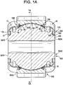
- a spherical bearing is generally designated by the numeral 500.
- the spherical bearing 500 has an inner ring 560 disposed partially in an outer ring 550.
- a seal 10 (e.g., a seal having triangular cross section) extends between the inner ring 560 and the outer ring 550 and defines a cavity 19 therebetween proximate each axial end of the outer ring 560.
- grease 21 or another lubricant is disposed in the cavity. 19.
- the outer ring 550 has two fractures F1, F2 extending axially therethrough so that the outer ring 550 defines a first segment 550A and a second segment 550B.
- a one piece swaged outer ring may be employed without departing from the broader aspects disclosed herein.
- a SpreadLock ® seal 98 e.g., V-shaped seal
- the spherical bearing 500 includes an outer ring 550 the outer ring 550 defines a spherical radially inner facing surface 551 defining a cavity 552 in the outer ring 550.
- the outer ring 550 defines a radially inward extending flange 553 that is spaced apart from an axially facing end 555 of the outer ring.
- the radially inward extending flange 553 and the axially facing end 555 define a radially inward facing groove 554.
- the inner ring 560 defining a spherical exterior surface 561 and having a radially outward extending flange 562 on an axial end 563A, 563B of the inner ring, the radially outward extending flange 562 defining an axially outward facing shoulder 565 and a radially outward facing shoulder 566.
- the first axial end 10A is secured to the axially outward facing shoulder 565 and/or the radially outward facing shoulder 566.
- the first axial end 10A slidingly engages the axially outward facing shoulder 565 and/or the radially outward facing shoulder 566.
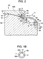
- the seal 10 includes an annular body portion 10C having an arcuate cross section extending between a first axial end 10A and a second axial end 10B.
- the second axial end 10B is positioned radially outward from the first axial end 10A.
- a first retaining ring 12 is embedded in the first axial end 10A.
- the first retaining ring 12 has a rectilinear cross section and is covered with an elastomeric material. For example, surrounded by an elastomeric material 12A, 12B and 12C ( FIG. 2 ) 112A, 112B and 112C ( FIG. 4 ).
- the elastomeric material is nitrile.
- the elastomeric material 12A, 12B and 12C ( FIG. 2 ) 112A, 112B and 112C ( FIG. 4 ) helps frictionally engage and secure the retaining ring 12, 112 in compression with the shoulders 565, 566, 665 and 666.
- the first retaining ring is manufactured from a metallic material that provides sufficient stiffness and rigidity to retain the seal 10, 110, 210, 310, 410 in frictional engagement with the shoulders 565, 566, 665 and 666 during misalignment of the outer ring 550 relative to the inner ring 560.
- the elastomeric material 12A, 112A on the first end 10A, 110A respectively is flush with the respective axial end 560A, 560B, 660A or 660B of the inner ring 560 or 660, to cause debris to fall off of the seal 10, 110 and away from the radially outward facing shoulder 56 and away from the exterior surface 561.
- the annular body portion 10C is a boot seal manufactured from an elastomeric material, such as but not limited to rubber or nitrile.
- second axial end 10B comprises an elastomeric material, such as but not limited to rubber or nitrile.
- a second retaining ring 14 is positioned proximate the second axial end 10B.
- a scraper seal 16 extends radially inward from the second end 10B.
- the scraper seal 16 has a wedge shaped cross section and is configured to scrape debris off of the spherical exterior surface 561.
- the second retaining ring 14 has an L-shaped cross section defined by an elongate first leg 14A extending radially outward and a second leg 14B extending axially outward from the first leg 14A, the first leg 14A being seated in a base portion 18 of the second axial end 10B.
- the base portion 18 is positioned radially outward from the first leg 14A.
- the second retaining ring 14 cooperates with the base portion 18 of the second end 10A to frictionally retain the second end 10A in compression in the groove 554.
- the scraper seal 16 deflects against the exterior surface 561 of the inner ring 560 causing force in the direction of the arrow K and a moment as indicated by the arrow M in FIG. 2 which further maintains the second end 10B engaged in compression in the groove 554, by
- the second retaining ring 14 assists in securing the first segment 550A to the second segment 550B of the outer ring 550.
- the scraper seal 16 includes a biasing feature configured to urge the second axial end 10B radially outward upon application of a force to the scraper seal 16.
- the scraper seal 16 exerts a radially outward force K on the second axial end 10B to secure the second axial end 10B in the radially inward facing groove 554.
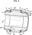
- the second retaining ring 114 has a C-shaped cross section, defined by a first L-shaped leg 114B and a second L-shaped leg 114C coupled to one another by a web 114E.
- the second retaining ring 114 has a receiving area 114D between the first L-shaped leg 114B and a second L-shaped leg 114C.
- the axially facing end 655 of the outer ring 650 defines a T-shaped flange comprising the radially inward extending flange 653 and a radially outward extending flange 653'.
- the second retaining ring 114 has a C-shaped cross section, defined by a first L-shaped leg 114B and a second L-shaped leg 114C coupled to one another by a web 114E, the second retaining ring 114 having a receiving area 114D between the first L-shaped leg 114B and a second L-shaped leg 114C, wherein the T-shaped head is disposed in the receiving area 114D.
- the C-shaped cross section and the T-shaped head cooperate in a labyrinth manner to retain the seal 10, 110 in the groove 554 and to assists in securing the first segment 550A to the second segment 550B of the outer ring 550.
- the first retaining ring 212,312, and 412 for the bearing 1100 has a circular cross section and comprises an elastomeric material, such as but not limited to rubber or nitrile.
- the second retaining ring 214 has a J-shaped cross section defined by an elongate first leg 214A extending radially outward and transitioning into an axially directed second leg 214 and a third leg 214C extending radially inward from the second leg 214B.
- the outer ring 750 includes a radially outward facing groove 754 for receiving the third leg 214C.
- the first leg 214A compresses the second end 210B of the seal 210 against an axial end of the outer ring 750.
- the second retaining ring 314 has an L-shaped cross section defined by an elongate first leg 314A extending radially outward and transitioning into an axially directed second leg 314B.
- the outer ring 850 includes a radially outward facing shoulder 854 for receiving the second leg 314B.
- the first leg 314A compresses the second end 310B of the seal 310 against an axial end of the outer ring 850.
- the second retaining ring 414 for the bearing 1100 has a L-shaped cross section defined by an elongate first leg 414A extending radially outward and transitioning into an axially directed second leg 414B and a third leg 414C extending angularly inward from the second leg 414B.
- the outer ring 1150 includes a radially outward facing groove 1154 for receiving the third leg 414C.
- the first leg 414A compresses the second end 410B of the seal 410 against an axial end of the outer ring 1150.
- the seals 10, 110, 210, 310 and 410 may be interchanged with any of the bearing assemblies 500 ( FIG. 1A ), 600 ( FIG. 3 ), 700 ( FIG. 5A ), 800 ( FIG. 6A ) and 1100 ( FIG. 7A ).
- the bearing assemblies 500 ( FIG. 1A ), 600 ( FIG. 3 ), 700 ( FIG. 5A ), 800 ( FIG. 6A ) and 1100 ( FIG. 7A ) with the seals 10, 110, 210, 310 and 410 therein, respectively, may be utilized in a variety of situations and applications, including, but not limited to, bearings for vehicle suspension systems (e.g., FIGS. 8A, 8B and 9 , see strut 222 and with the bearing assemblies (having the seal 10, 110) positioned in pivot connections 224 and 226) and steering systems for heavy haul trucks 220.
- bearings for vehicle suspension systems e.g., FIGS. 8A, 8B and 9 , see strut 222 and with the bearing assemblies (having the seal 10, 110) positioned in pivot connections 224 and 226) and steering systems for heavy haul trucks 220.
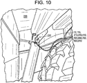
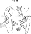
- the bearing assemblies may be utilized in a suspension system and/or a steering system of mining and construction vehicles 220 for pivotally or rotationally connecting structural components to the vehicle such as, for example, struts or other telescopic dampers, hydraulic cylinders (e.g., FIG. 10 see upper hoist cylinder with a bearing (having the seal 10, 110) located in at pivot connection 230) or other mechanical and pneumatic actuators, a panhard link (e.g., FIG. 11 , see panhard link 241 with bearings (having the seal 10, 110) located in pivot connections 240) or other link of a multi-link suspension system, and the like.
- hydraulic cylinders e.g., FIG. 10 see upper hoist cylinder with a bearing (having the seal 10, 110) located in at pivot connection 230) or other mechanical and pneumatic actuators
- a panhard link e.g., FIG. 11 , see panhard link 241 with bearings (having the seal 10, 110) located in pivot connections 240
- bearing assemblies having the seals 10 and 110 is not limited in this regard as it is contemplated to use such bearing assemblies in other applications, such as, for example, military vehicles including a tank or transport vehicle, and other heavy duty equipment, such as, for example, heavy duty pick-up trucks, dump trucks, fire trucks, and the like.
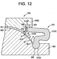
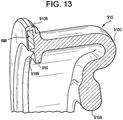
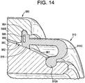
- the seal 910 of FIGS. 12-14 are similar to the seal 10 of FIG. 2 . Therefore, similar elements are designated with reference numbers starting with the numeral 9.
- the scraper seal 916 deflects against the exterior surface 961 of the inner ring 960 causing force in the direction of the arrow K and a movement as indicated by the arrow M in FIG. 12 which further maintains the second end 910B engaged in compression in the groove 954, by
- the second retaining ring 914 assists in securing the first segment 950A to the second segment 950B of the outer ring 550.
- the scraper seal is configured to scrape debris off of the exterior surface 961 by pushing or shoveling the debris axially outward during misalignment of the outer ring 950 relative to the inner ring 960 thereby preventing the debris from entering the cavity 952 between the inner ring 960 and the outer ring 950.
- the scraper seal 916 incudes a biasing feature configured to urge the second axial end 910B radially outward upon application of a force to the scraper seal 916.
- the scraper seal 916 exerts a radially outward force K on the second axial end 910B to secure the second axial end 910B in the radially inward facing groove 954. As shown in FIGS.
- the scraper seal 916 defines a base 916B that is radially aligned with the second axial end 910B and the radially inward facing groove 954.
- a lubricious liner 999 e.g., self lubricating liner, Polytetrafluoroethylene (PTFE)
- PTFE Polytetrafluoroethylene
- the second end 910B of the seal 910 includes a flat washer shaped (e.g., rectilinear cross section) retaining ring 998 therein.
- the first axial end 910A slidingly engages a groove 965 formed in the inner ring 960.
- the first axial end 910A is secured in the groove 965.
- the scraper seal 916 is made from an elastomeric material such as nitrile.
- the seal 910 is made from an elastomeric material such as nitrile.
- the scraper seal 916 is made from material that is stiffer and/or harder than the first end 910A, the annular body portion 910C and the second axial end 910B, which are made from an elastomeric material such as nitrile.
- the scraper seal 916 is integral with the first end 910A, the annular body portion 910C and the second axial end 910B. In one embodiment, the scraper seal 916 according to claim 1, is manufactured separate from the first end 910A, the annular body portion 910C and the second axial end 910B and a base portion 916B ( FIG. 12 ) is secured to a portion of the seal 910 proximate the second axial end 910B via a suitable bonding method.
Landscapes
- Engineering & Computer Science (AREA)
- General Engineering & Computer Science (AREA)
- Mechanical Engineering (AREA)
- Sealing Devices (AREA)
Claims (13)
- Dichtung (10, 910) für ein Gelenklager (500, 600, 700, 800, 1100), umfassend einen Außenring (550, 950) und einen Innenring (560, 960), wobei die Dichtung (10, 910) Folgendes umfasst:einen ringförmigen Körperabschnitt (10C, 910C), der einen bogenförmigen Querschnitt aufweist, der sich zwischen einem ersten axialen Ende (10A, 910A) und einem zweiten axialen Ende (10B, 910B) erstreckt, wobei das zweite axiale Ende (10B, 910B) radial auswärts von dem ersten axialen Ende (10A, 910A) angeordnet ist; dadurch gekennzeichnet, dassein erster Haltering (12) an dem ersten axialen Ende (10A, 910A) angeordnet ist;eine Abstreifdichtung (16, 916) sich von dem zweiten axialen Ende (10B, 910B) radial nach innen erstreckt;die Abstreifdichtung (16, 916) steifer und härter ist als das erste axiale Ende (10A, 910A), der ringförmige Körperabschnitt (910C) und das zweite axiale Ende (910B), einstückig mit dem ersten axialen Ende (910A), dem ringförmigen Körperabschnitt (910C) und dem zweiten axialen Ende (910B) ist, die aus einem Elastomermaterial hergestellt sind, und dazu ausgestaltet ist, Verunreinigungen von der sphärischen Außenfläche (561, 961) des Innenrings (560, 960) abzustreifen; unddie Abstreifdichtung (16, 916) ein Vorspannmerkmal umfasst, das derart ausgestaltet ist, dass, wenn die Dichtung (10, 910) in einem Lager montiert ist, eine Kraft auf die Abstreifdichtung (16, 916) aufgebracht wird, die das zweite axiale Ende (10B, 910B) radial nach außen drängt, um das zweite axiale Ende (10B, 910B) in einer radial nach innen weisenden Nut (554, 954) des Außenrings (560, 960) zu sichern.
- Dichtung (10, 910) nach Anspruch 1, wobei die Dichtung ein Elastomermaterial umfasst.
- Dichtung (10, 910) nach Anspruch 1, ferner umfassend einen zweiten Haltering (14, 914), der in der Nähe des zweiten axialen Endes (10B, 910B) angeordnet ist, wobei der zweite Haltering (14, 914) einen geradlinigen Querschnitt, einen L-förmigen Querschnitt, einen J-förmigen Querschnitt oder einen C-förmigen Querschnitt aufweist.
- Dichtung (10, 910) nach Anspruch 1, wobei der erste Haltering (12, 912) einen geradlinigen Querschnitt aufweist und mit einem Elastomermaterial abgedeckt in dem ersten axialen Ende (10A, 910A) eingebettet ist oder der erste Haltering (212, 312, 412) einen kreisförmigen Querschnitt aufweist und ein Elastomermaterial umfasst.
- Gelenklager (500, 600, 700, 800, 1100), umfassend:einen Außenring (550, 950), der eine sphärische, radial nach innen weisende Fläche (551, 951) definiert, die einen Hohlraum (552, 952) in dem Außenring definiert;einen Innenring (560, 960), der eine sphärische Außenfläche (561, 961) definiert, wobei der Innenring (560, 960) zumindest teilweise in dem Hohlraum angeordnet ist;eine Dichtung (10, 910), die sich zwischen dem Innenring (560, 960) und dem Außenring (550, 950) erstreckt, wobei die Dichtung Folgendes umfasst:einen ringförmigen Körperabschnitt (10C, 910C), der einen bogenförmigen Querschnitt aufweist, der sich zwischen einem ersten axialen Ende (10A, 910A) und einem zweiten (10B, 910B) axialen Ende erstreckt, wobei das zweite axiale Ende (10B, 910B) radial auswärts von dem ersten axialen Ende (10A, 910A) angeordnet ist; dadurch gekennzeichnet, dassein erster Haltering (12) an dem ersten axialen Ende (10A, 910A) angeordnet ist;eine Abstreifdichtung (16, 916) sich von dem zweiten axialen Ende (10B, 910B) radial nach innen erstreckt;die Abstreifdichtung (16, 916) steifer und härter ist als das erste axiale Ende (910A), der ringförmige Körperabschnitt (910C) und das zweite axiale Ende (910B), einstückig mit dem ersten axialen Ende (910A), dem ringförmigen Körperabschnitt (910C) und dem zweiten axialen Ende (910B) ist, die aus einem Elastomermaterial hergestellt sind, und dazu ausgestaltet ist, Verunreinigungen von der sphärischen Außenfläche abzustreifen; unddie Abstreifdichtung (16, 916) ein Vorspannmerkmal umfasst, das dazu ausgestaltet ist, bei Aufbringen einer Kraft auf die Abstreifdichtung (16, 916) das zweite axiale Ende (10B, 910B) radial nach außen zu drängen, um das zweite axiale Ende (910B) in einer radial nach innen weisenden Nut (554, 954) des Außenrings (550, 950) zu sichern.
- Gelenklager (500, 600, 700, 800, 1100) nach Anspruch 5, ferner umfassend einen zweiten Haltering (14), der in der Nähe des zweiten axialen Endes (10B) angeordnet ist, wobei der zweite Haltering (14) einen geradlinigen Querschnitt, einen L-förmigen Querschnitt, einen J-förmigen Querschnitt oder einen C-förmigen Querschnitt aufweist.
- Gelenklager (500, 600, 700, 800, 1100) nach Anspruch 5, wobei die Dichtung ein Elastomermaterial umfasst.
- Gelenklager (500, 600, 700, 800, 1100) nach Anspruch 5, wobei der Außenring (550) einen Flansch (553) definiert, der sich radial nach innen erstreckt, der von einem in axiale Richtung weisenden Ende (555) des Außenrings (550) beabstandet ist, wobei der Flansch (553), der sich radial nach innen erstreckt, und das in axiale Richtung weisende Ende eine radial nach innen weisende Nut (554) definieren; und
die Abstreifdichtung (16) eine radial nach außen gerichtete Kraft auf das zweite axiale Ende ausübt, um das zweite axiale Ende (10B) in der radial nach innen weisenden Nut (554) zu sichern. - Gelenklager (500, 600, 700, 800, 1100) nach Anspruch 5, wobei der erste Haltering (12) einen geradlinigen Querschnitt aufweist und mit einem Elastomermaterial abgedeckt in dem ersten axialen Ende (10A, 910A) eingebettet ist oder der erste Haltering (12) einen kreisförmigen Querschnitt aufweist und ein Elastomermaterial umfasst.
- Gelenklager (500, 600, 700, 800, 1100) nach Anspruch 5, wobei der Innenring (560) an einem axialen (560A, 560B, 660A, 660B) Ende davon einen Flansch (562) aufweist, der sich radial nach außen erstreckt, wobei der Flansch, der sich radial nach außen erstreckt, eine axial nach außen weisende Schulter (566) und eine radial nach außen weisende Schulter (565) definiert;
das Elastomermaterial des ersten axialen Endes (10A) an der axial nach außen weisenden Schulter und/oder der radial nach außen weisenden Schulter (565) gesichert ist; und
das erste axiale Ende (10A) bündig mit dem axialen Ende (560A, 560B, 660A, 660B) des Innenrings (560) ist, sodass Verunreinigungen von der Dichtung herunter und von der radial nach außen weisenden Schulter (56) ab und von der Außenfläche (561) abfallen. - Gelenklager (500, 600, 700, 800, 1100) nach Anspruch 5, wobei der Innenring (560) an einem axialen Ende (560A, 560B, 660A, 660B) davon einen Flansch (562) aufweist, der sich radial nach außen erstreckt, wobei der Flansch (562), der sich radial nach außen erstreckt, eine axial nach außen weisende Schulter (565) und eine radial nach außen weisende Schulter (566) definiert; und
das erste axiale Ende (10A) gleitend mit der axial nach außen weisenden Schulter (565) und/oder der radial nach außen weisenden Schulter (565) in Eingriff tritt. - Gelenklager (500, 600, 700, 800, 1100) nach Anspruch 5, wobei die Abstreifdichtung (16, 916) eine Basis (910B) definiert, die radial mit dem zweiten axialen Ende (10B) und der radial nach innen weisenden Nut (554) ausgerichtet ist.
- Gelenklager (500, 600, 700, 800, 1100) nach Anspruch 5, wobei der Außenring durch ihn hindurch mindestens zwei sich axial erstreckende Bruchstellen (F1, F2) umfasst, sodass der Außenring ein erstes Segment (550A) und ein zweites Segment (550B) definiert.
Applications Claiming Priority (1)
| Application Number | Priority Date | Filing Date | Title |
|---|---|---|---|
| US201462091928P | 2014-12-15 | 2014-12-15 |
Publications (2)
| Publication Number | Publication Date |
|---|---|
| EP3034897A1 EP3034897A1 (de) | 2016-06-22 |
| EP3034897B1 true EP3034897B1 (de) | 2020-04-08 |
Family
ID=54849830
Family Applications (1)
| Application Number | Title | Priority Date | Filing Date |
|---|---|---|---|
| EP15199806.9A Active EP3034897B1 (de) | 2014-12-15 | 2015-12-14 | Gelenklager mit ringdichtung mit einem zusätzlichen, daraus fortgesetzten dichtungsbein |
Country Status (2)
| Country | Link |
|---|---|
| US (1) | US9829044B2 (de) |
| EP (1) | EP3034897B1 (de) |
Families Citing this family (8)
| Publication number | Priority date | Publication date | Assignee | Title |
|---|---|---|---|---|
| US10288173B2 (en) * | 2014-10-06 | 2019-05-14 | Caterpillar Inc. | Seal member for joint of machine and method of assembling same |
| US10487878B2 (en) * | 2016-07-01 | 2019-11-26 | Roller Bearing Company Of America, Inc. | Multiple stage seal for a bearing assembly |
| JP6605530B2 (ja) * | 2017-03-31 | 2019-11-13 | ファナック株式会社 | ボールジョイントのシール部材 |
| US10598219B2 (en) | 2017-09-18 | 2020-03-24 | Roller Bearing Company Of America, Inc. | Bearing and sealing arrangement for joints in heavy duty vehicles |
| DE102018109484A1 (de) | 2018-04-20 | 2019-10-24 | Schaeffler Technologies AG & Co. KG | Dichtungsring für Gelenklager |
| US20230323917A1 (en) * | 2022-04-07 | 2023-10-12 | Federal-Mogul Motorparts Llc | Socket joint and method of manufacturing |
| US12281704B2 (en) * | 2023-01-13 | 2025-04-22 | Caterpillar Inc. | Seal member for joint assembly of a machine and systems, methods, and assemblies thereof |
| DE102023131609A1 (de) * | 2023-11-14 | 2025-05-15 | Schaeffler Technologies AG & Co. KG | Kippsegmenteinheit für eine Rotorwelle einer Windenergieanlage |
Family Cites Families (33)
| Publication number | Priority date | Publication date | Assignee | Title |
|---|---|---|---|---|
| US3848938A (en) | 1973-02-28 | 1974-11-19 | Torrington Co | Bearing and bearing seal |
| US4249782A (en) | 1979-09-11 | 1981-02-10 | Deere & Company | Self-aligning bearing and seal |
| US4331367A (en) | 1980-11-17 | 1982-05-25 | Gulf & Western Manufacturing Company | Sealed compound bearing |
| DE8536143U1 (de) * | 1985-12-21 | 1986-02-20 | SKF Gleitlager GmbH, 6625 Püttlingen | Anordnung zur Abdichtung von Lagern, insbesondere von Gelenklagern mit aus zwei Halbschalen zusammengesetztem Außenring |
| US5066159A (en) | 1991-02-08 | 1991-11-19 | Trw Inc. | Ball joint with integral seal |
| JPH0518411A (ja) * | 1991-07-11 | 1993-01-26 | Somitsuku Ishikawa:Kk | 球面滑り軸受 |
| JP3340553B2 (ja) | 1994-03-17 | 2002-11-05 | 日東工器株式会社 | 管継手 |
| US5931597A (en) | 1997-10-16 | 1999-08-03 | Trw Inc. | Ball joint |
| DE19834678C2 (de) * | 1998-07-31 | 2003-10-16 | Skf Gleitlager Gmbh | Abgedichtetes, Schwenkbewegungen ausführendes Gelenklager |
| BR0100428A (pt) | 2001-01-24 | 2004-06-22 | Dana Industrial Ltda | Construção de mancal e caixa para articulação esférica |
| US6626575B2 (en) | 2001-06-07 | 2003-09-30 | Roller Bearing Company Of America | Spherical plain bearing with spread lock dual sealing means |
| GB2400149B (en) | 2003-04-01 | 2005-03-23 | Minebea Co Ltd | A sealed bearing |
| US7438493B2 (en) | 2005-11-03 | 2008-10-21 | ZF Lemförder Metallwaren AG | Cross axis ball and socket joint with sealing ring for cross axis sleeve ends |
| US20070122232A1 (en) | 2005-11-28 | 2007-05-31 | Tomasz Buchner | Ball joint assembly |
| US9157480B2 (en) | 2006-07-19 | 2015-10-13 | Roller Bearing Company Of America, Inc. | Two stage seal for a bearing assembly |
| US7481595B2 (en) | 2006-09-06 | 2009-01-27 | Trw Automotive U.S. Llc | Ball joint |
| WO2008074063A1 (en) | 2006-12-18 | 2008-06-26 | Zf Boge Elastmetall Australia Pty Ltd | Ball joint |
| DE102006061974A1 (de) | 2006-12-21 | 2008-07-10 | Zf Friedrichshafen Ag | Kugelgelenk mit Verschlussring |
| JP5052264B2 (ja) | 2007-09-05 | 2012-10-17 | 光陽精機株式会社 | 制振用ダンパー、およびその設置方法 |
| DE102007055251A1 (de) * | 2007-11-16 | 2009-07-16 | Zf Friedrichshafen Ag | Gelenk- und/oder Lageranordnung |
| US8414215B2 (en) | 2008-11-07 | 2013-04-09 | Trw Automotive U.S. Llc | Sealing structure for use with a ball and socket joint |
| US8622644B2 (en) | 2010-05-28 | 2014-01-07 | Caterpillar Inc. | Seal assembly and method for forming a seal assembly |
| US8690690B2 (en) | 2010-06-30 | 2014-04-08 | American Axle & Manufacturing, Inc. | Constant velocity joint with quick connector and method |
| WO2012068237A1 (en) * | 2010-11-16 | 2012-05-24 | Roller Bearing Company Of America, Inc. | Spherical plain bearing and method for assembling the same |
| US9316257B2 (en) | 2011-04-01 | 2016-04-19 | Roller Bearing Company Of America, Inc. | Spherical bearing with sealing member member |
| US8783953B2 (en) | 2011-07-21 | 2014-07-22 | Roller Bearing Company Of America, Inc. | Low friction seal for bearings |
| US20130043719A1 (en) | 2011-08-18 | 2013-02-21 | Caterpillar Inc. | Elastomeric Bearing for Equalizer Bar of Undercarriage |
| US9103450B2 (en) | 2012-04-05 | 2015-08-11 | Cerro E.M.S. | Emergency control gas ball valve |
| US8967868B2 (en) | 2012-09-27 | 2015-03-03 | Caterpillar Inc. | Threaded bearing retainer |
| WO2014089434A1 (en) | 2012-12-07 | 2014-06-12 | Roller Bearing Company Of America, Inc. | Two stage seal for a bearing assembly |
| US9562567B2 (en) | 2014-02-07 | 2017-02-07 | Roller Bearing Company Of America, Inc. | Spherical bearing with axially compressed annular seal |
| EP2905486B1 (de) | 2014-02-11 | 2019-05-29 | Roller Bearing Company of America, Inc. | Verpresste lageranordnung mit darauf montiertem flansch |
| CN204025369U (zh) | 2014-06-23 | 2014-12-17 | 泛科轴承集团有限公司 | 能抗振散热的外球面球轴承 |
-
2015
- 2015-12-14 EP EP15199806.9A patent/EP3034897B1/de active Active
- 2015-12-14 US US14/967,541 patent/US9829044B2/en active Active
Non-Patent Citations (1)
| Title |
|---|
| None * |
Also Published As
| Publication number | Publication date |
|---|---|
| US20160169284A1 (en) | 2016-06-16 |
| US9829044B2 (en) | 2017-11-28 |
| EP3034897A1 (de) | 2016-06-22 |
Similar Documents
| Publication | Publication Date | Title |
|---|---|---|
| EP3034897B1 (de) | Gelenklager mit ringdichtung mit einem zusätzlichen, daraus fortgesetzten dichtungsbein | |
| US7597410B2 (en) | Track chain joint with radial seal unit | |
| US8801318B2 (en) | Joint | |
| EP2552766B1 (de) | Dichtungsbaugruppe für eine spurstift-gelenkbaugruppe | |
| US8678696B2 (en) | Seal assembly for track pin joint assembly | |
| EP3263927B1 (de) | Zweistufige dichtung für lageranordnung | |
| AU2015328283B2 (en) | Seal member for joint of machine | |
| JP5423409B2 (ja) | シーリングシステム | |
| US10598219B2 (en) | Bearing and sealing arrangement for joints in heavy duty vehicles | |
| US9958011B2 (en) | Bearing assembly having surface protrusions and a seal | |
| US10442480B2 (en) | Coating for seal assembly | |
| WO2012143991A1 (ja) | シーリングシステム | |
| EP2929198B1 (de) | Zweistufige dichtung für lageranordnung | |
| US9822883B2 (en) | Load ring for seal assembly and seal assembly of machine | |
| EP2905485B1 (de) | Dichtung und Ankersystem für Pendelkugellager | |
| US20160377180A1 (en) | Double sided outer seal | |
| KR20220024809A (ko) | 토크 저항성 씰 |
Legal Events
| Date | Code | Title | Description |
|---|---|---|---|
| PUAI | Public reference made under article 153(3) epc to a published international application that has entered the european phase |
Free format text: ORIGINAL CODE: 0009012 |
|
| AK | Designated contracting states |
Kind code of ref document: A1 Designated state(s): AL AT BE BG CH CY CZ DE DK EE ES FI FR GB GR HR HU IE IS IT LI LT LU LV MC MK MT NL NO PL PT RO RS SE SI SK SM TR |
|
| AX | Request for extension of the european patent |
Extension state: BA ME |
|
| STAA | Information on the status of an ep patent application or granted ep patent |
Free format text: STATUS: REQUEST FOR EXAMINATION WAS MADE |
|
| 17P | Request for examination filed |
Effective date: 20161222 |
|
| RBV | Designated contracting states (corrected) |
Designated state(s): AL AT BE BG CH CY CZ DE DK EE ES FI FR GB GR HR HU IE IS IT LI LT LU LV MC MK MT NL NO PL PT RO RS SE SI SK SM TR |
|
| STAA | Information on the status of an ep patent application or granted ep patent |
Free format text: STATUS: EXAMINATION IS IN PROGRESS |
|
| 17Q | First examination report despatched |
Effective date: 20190104 |
|
| GRAP | Despatch of communication of intention to grant a patent |
Free format text: ORIGINAL CODE: EPIDOSNIGR1 |
|
| STAA | Information on the status of an ep patent application or granted ep patent |
Free format text: STATUS: GRANT OF PATENT IS INTENDED |
|
| INTG | Intention to grant announced |
Effective date: 20191001 |
|
| GRAS | Grant fee paid |
Free format text: ORIGINAL CODE: EPIDOSNIGR3 |
|
| GRAA | (expected) grant |
Free format text: ORIGINAL CODE: 0009210 |
|
| STAA | Information on the status of an ep patent application or granted ep patent |
Free format text: STATUS: THE PATENT HAS BEEN GRANTED |
|
| AK | Designated contracting states |
Kind code of ref document: B1 Designated state(s): AL AT BE BG CH CY CZ DE DK EE ES FI FR GB GR HR HU IE IS IT LI LT LU LV MC MK MT NL NO PL PT RO RS SE SI SK SM TR |
|
| REG | Reference to a national code |
Ref country code: AT Ref legal event code: REF Ref document number: 1254764 Country of ref document: AT Kind code of ref document: T Effective date: 20200415 Ref country code: CH Ref legal event code: EP |
|
| REG | Reference to a national code |
Ref country code: IE Ref legal event code: FG4D |
|
| REG | Reference to a national code |
Ref country code: DE Ref legal event code: R096 Ref document number: 602015050191 Country of ref document: DE |
|
| REG | Reference to a national code |
Ref country code: NL Ref legal event code: MP Effective date: 20200408 |
|
| REG | Reference to a national code |
Ref country code: LT Ref legal event code: MG4D |
|
| PG25 | Lapsed in a contracting state [announced via postgrant information from national office to epo] |
Ref country code: IS Free format text: LAPSE BECAUSE OF FAILURE TO SUBMIT A TRANSLATION OF THE DESCRIPTION OR TO PAY THE FEE WITHIN THE PRESCRIBED TIME-LIMIT Effective date: 20200808 Ref country code: NO Free format text: LAPSE BECAUSE OF FAILURE TO SUBMIT A TRANSLATION OF THE DESCRIPTION OR TO PAY THE FEE WITHIN THE PRESCRIBED TIME-LIMIT Effective date: 20200708 Ref country code: FI Free format text: LAPSE BECAUSE OF FAILURE TO SUBMIT A TRANSLATION OF THE DESCRIPTION OR TO PAY THE FEE WITHIN THE PRESCRIBED TIME-LIMIT Effective date: 20200408 Ref country code: GR Free format text: LAPSE BECAUSE OF FAILURE TO SUBMIT A TRANSLATION OF THE DESCRIPTION OR TO PAY THE FEE WITHIN THE PRESCRIBED TIME-LIMIT Effective date: 20200709 Ref country code: PT Free format text: LAPSE BECAUSE OF FAILURE TO SUBMIT A TRANSLATION OF THE DESCRIPTION OR TO PAY THE FEE WITHIN THE PRESCRIBED TIME-LIMIT Effective date: 20200817 Ref country code: NL Free format text: LAPSE BECAUSE OF FAILURE TO SUBMIT A TRANSLATION OF THE DESCRIPTION OR TO PAY THE FEE WITHIN THE PRESCRIBED TIME-LIMIT Effective date: 20200408 Ref country code: LT Free format text: LAPSE BECAUSE OF FAILURE TO SUBMIT A TRANSLATION OF THE DESCRIPTION OR TO PAY THE FEE WITHIN THE PRESCRIBED TIME-LIMIT Effective date: 20200408 Ref country code: SE Free format text: LAPSE BECAUSE OF FAILURE TO SUBMIT A TRANSLATION OF THE DESCRIPTION OR TO PAY THE FEE WITHIN THE PRESCRIBED TIME-LIMIT Effective date: 20200408 |
|
| REG | Reference to a national code |
Ref country code: AT Ref legal event code: MK05 Ref document number: 1254764 Country of ref document: AT Kind code of ref document: T Effective date: 20200408 |
|
| PG25 | Lapsed in a contracting state [announced via postgrant information from national office to epo] |
Ref country code: LV Free format text: LAPSE BECAUSE OF FAILURE TO SUBMIT A TRANSLATION OF THE DESCRIPTION OR TO PAY THE FEE WITHIN THE PRESCRIBED TIME-LIMIT Effective date: 20200408 Ref country code: RS Free format text: LAPSE BECAUSE OF FAILURE TO SUBMIT A TRANSLATION OF THE DESCRIPTION OR TO PAY THE FEE WITHIN THE PRESCRIBED TIME-LIMIT Effective date: 20200408 Ref country code: HR Free format text: LAPSE BECAUSE OF FAILURE TO SUBMIT A TRANSLATION OF THE DESCRIPTION OR TO PAY THE FEE WITHIN THE PRESCRIBED TIME-LIMIT Effective date: 20200408 Ref country code: BG Free format text: LAPSE BECAUSE OF FAILURE TO SUBMIT A TRANSLATION OF THE DESCRIPTION OR TO PAY THE FEE WITHIN THE PRESCRIBED TIME-LIMIT Effective date: 20200708 |
|
| PG25 | Lapsed in a contracting state [announced via postgrant information from national office to epo] |
Ref country code: AL Free format text: LAPSE BECAUSE OF FAILURE TO SUBMIT A TRANSLATION OF THE DESCRIPTION OR TO PAY THE FEE WITHIN THE PRESCRIBED TIME-LIMIT Effective date: 20200408 |
|
| REG | Reference to a national code |
Ref country code: DE Ref legal event code: R097 Ref document number: 602015050191 Country of ref document: DE |
|
| PG25 | Lapsed in a contracting state [announced via postgrant information from national office to epo] |
Ref country code: SM Free format text: LAPSE BECAUSE OF FAILURE TO SUBMIT A TRANSLATION OF THE DESCRIPTION OR TO PAY THE FEE WITHIN THE PRESCRIBED TIME-LIMIT Effective date: 20200408 Ref country code: EE Free format text: LAPSE BECAUSE OF FAILURE TO SUBMIT A TRANSLATION OF THE DESCRIPTION OR TO PAY THE FEE WITHIN THE PRESCRIBED TIME-LIMIT Effective date: 20200408 Ref country code: AT Free format text: LAPSE BECAUSE OF FAILURE TO SUBMIT A TRANSLATION OF THE DESCRIPTION OR TO PAY THE FEE WITHIN THE PRESCRIBED TIME-LIMIT Effective date: 20200408 Ref country code: DK Free format text: LAPSE BECAUSE OF FAILURE TO SUBMIT A TRANSLATION OF THE DESCRIPTION OR TO PAY THE FEE WITHIN THE PRESCRIBED TIME-LIMIT Effective date: 20200408 Ref country code: CZ Free format text: LAPSE BECAUSE OF FAILURE TO SUBMIT A TRANSLATION OF THE DESCRIPTION OR TO PAY THE FEE WITHIN THE PRESCRIBED TIME-LIMIT Effective date: 20200408 Ref country code: ES Free format text: LAPSE BECAUSE OF FAILURE TO SUBMIT A TRANSLATION OF THE DESCRIPTION OR TO PAY THE FEE WITHIN THE PRESCRIBED TIME-LIMIT Effective date: 20200408 Ref country code: RO Free format text: LAPSE BECAUSE OF FAILURE TO SUBMIT A TRANSLATION OF THE DESCRIPTION OR TO PAY THE FEE WITHIN THE PRESCRIBED TIME-LIMIT Effective date: 20200408 Ref country code: IT Free format text: LAPSE BECAUSE OF FAILURE TO SUBMIT A TRANSLATION OF THE DESCRIPTION OR TO PAY THE FEE WITHIN THE PRESCRIBED TIME-LIMIT Effective date: 20200408 |
|
| PLBE | No opposition filed within time limit |
Free format text: ORIGINAL CODE: 0009261 |
|
| STAA | Information on the status of an ep patent application or granted ep patent |
Free format text: STATUS: NO OPPOSITION FILED WITHIN TIME LIMIT |
|
| PG25 | Lapsed in a contracting state [announced via postgrant information from national office to epo] |
Ref country code: PL Free format text: LAPSE BECAUSE OF FAILURE TO SUBMIT A TRANSLATION OF THE DESCRIPTION OR TO PAY THE FEE WITHIN THE PRESCRIBED TIME-LIMIT Effective date: 20200408 Ref country code: SK Free format text: LAPSE BECAUSE OF FAILURE TO SUBMIT A TRANSLATION OF THE DESCRIPTION OR TO PAY THE FEE WITHIN THE PRESCRIBED TIME-LIMIT Effective date: 20200408 |
|
| 26N | No opposition filed |
Effective date: 20210112 |
|
| PG25 | Lapsed in a contracting state [announced via postgrant information from national office to epo] |
Ref country code: SI Free format text: LAPSE BECAUSE OF FAILURE TO SUBMIT A TRANSLATION OF THE DESCRIPTION OR TO PAY THE FEE WITHIN THE PRESCRIBED TIME-LIMIT Effective date: 20200408 |
|
| REG | Reference to a national code |
Ref country code: CH Ref legal event code: PL |
|
| GBPC | Gb: european patent ceased through non-payment of renewal fee |
Effective date: 20201214 |
|
| PG25 | Lapsed in a contracting state [announced via postgrant information from national office to epo] |
Ref country code: MC Free format text: LAPSE BECAUSE OF FAILURE TO SUBMIT A TRANSLATION OF THE DESCRIPTION OR TO PAY THE FEE WITHIN THE PRESCRIBED TIME-LIMIT Effective date: 20200408 |
|
| REG | Reference to a national code |
Ref country code: BE Ref legal event code: MM Effective date: 20201231 |
|
| PG25 | Lapsed in a contracting state [announced via postgrant information from national office to epo] |
Ref country code: IE Free format text: LAPSE BECAUSE OF NON-PAYMENT OF DUE FEES Effective date: 20201214 Ref country code: FR Free format text: LAPSE BECAUSE OF NON-PAYMENT OF DUE FEES Effective date: 20201231 Ref country code: LU Free format text: LAPSE BECAUSE OF NON-PAYMENT OF DUE FEES Effective date: 20201214 |
|
| PG25 | Lapsed in a contracting state [announced via postgrant information from national office to epo] |
Ref country code: CH Free format text: LAPSE BECAUSE OF NON-PAYMENT OF DUE FEES Effective date: 20201231 Ref country code: GB Free format text: LAPSE BECAUSE OF NON-PAYMENT OF DUE FEES Effective date: 20201214 Ref country code: LI Free format text: LAPSE BECAUSE OF NON-PAYMENT OF DUE FEES Effective date: 20201231 |
|
| PG25 | Lapsed in a contracting state [announced via postgrant information from national office to epo] |
Ref country code: TR Free format text: LAPSE BECAUSE OF FAILURE TO SUBMIT A TRANSLATION OF THE DESCRIPTION OR TO PAY THE FEE WITHIN THE PRESCRIBED TIME-LIMIT Effective date: 20200408 Ref country code: MT Free format text: LAPSE BECAUSE OF FAILURE TO SUBMIT A TRANSLATION OF THE DESCRIPTION OR TO PAY THE FEE WITHIN THE PRESCRIBED TIME-LIMIT Effective date: 20200408 Ref country code: CY Free format text: LAPSE BECAUSE OF FAILURE TO SUBMIT A TRANSLATION OF THE DESCRIPTION OR TO PAY THE FEE WITHIN THE PRESCRIBED TIME-LIMIT Effective date: 20200408 |
|
| PG25 | Lapsed in a contracting state [announced via postgrant information from national office to epo] |
Ref country code: MK Free format text: LAPSE BECAUSE OF FAILURE TO SUBMIT A TRANSLATION OF THE DESCRIPTION OR TO PAY THE FEE WITHIN THE PRESCRIBED TIME-LIMIT Effective date: 20200408 |
|
| PG25 | Lapsed in a contracting state [announced via postgrant information from national office to epo] |
Ref country code: BE Free format text: LAPSE BECAUSE OF NON-PAYMENT OF DUE FEES Effective date: 20201231 |
|
| PGFP | Annual fee paid to national office [announced via postgrant information from national office to epo] |
Ref country code: DE Payment date: 20221213 Year of fee payment: 8 |
|
| REG | Reference to a national code |
Ref country code: DE Ref legal event code: R119 Ref document number: 602015050191 Country of ref document: DE |
|
| PG25 | Lapsed in a contracting state [announced via postgrant information from national office to epo] |
Ref country code: DE Free format text: LAPSE BECAUSE OF NON-PAYMENT OF DUE FEES Effective date: 20240702 |
|
| PG25 | Lapsed in a contracting state [announced via postgrant information from national office to epo] |
Ref country code: DE Free format text: LAPSE BECAUSE OF NON-PAYMENT OF DUE FEES Effective date: 20240702 |
|
| PG25 | Lapsed in a contracting state [announced via postgrant information from national office to epo] |
Ref country code: IS Free format text: LAPSE BECAUSE OF NON-PAYMENT OF DUE FEES Effective date: 20200808 |