EP3035005B1 - Ensemble rotorique, debitmetre, rotor et appareil transportant de l'eau - Google Patents
Ensemble rotorique, debitmetre, rotor et appareil transportant de l'eau Download PDFInfo
- Publication number
- EP3035005B1 EP3035005B1 EP15199291.4A EP15199291A EP3035005B1 EP 3035005 B1 EP3035005 B1 EP 3035005B1 EP 15199291 A EP15199291 A EP 15199291A EP 3035005 B1 EP3035005 B1 EP 3035005B1
- Authority
- EP
- European Patent Office
- Prior art keywords
- rotor
- housing
- fluid
- closure cap
- drive
- Prior art date
- Legal status (The legal status is an assumption and is not a legal conclusion. Google has not performed a legal analysis and makes no representation as to the accuracy of the status listed.)
- Active
Links
Images

Classifications
-
- G—PHYSICS
- G01—MEASURING; TESTING
- G01F—MEASURING VOLUME, VOLUME FLOW, MASS FLOW OR LIQUID LEVEL; METERING BY VOLUME
- G01F1/00—Measuring the volume flow or mass flow of fluid or fluent solid material wherein the fluid passes through a meter in a continuous flow
- G01F1/05—Measuring the volume flow or mass flow of fluid or fluent solid material wherein the fluid passes through a meter in a continuous flow by using mechanical effects
- G01F1/06—Measuring the volume flow or mass flow of fluid or fluent solid material wherein the fluid passes through a meter in a continuous flow by using mechanical effects using rotating vanes with tangential admission
- G01F1/075—Measuring the volume flow or mass flow of fluid or fluent solid material wherein the fluid passes through a meter in a continuous flow by using mechanical effects using rotating vanes with tangential admission with magnetic or electromagnetic coupling to the indicating device
Definitions
- the invention relates to a rotor assembly for a flow meter for measuring a fluid flow in a fluid line.
- the rotor assembly has a rotor which can be arranged at least in sections within the fluid line.
- the invention relates to a rotor for a rotor assembly, a flow meter with a rotor assembly and a water-bearing household appliance with a flow meter.
- EP 2 071 296 A2 , EP 1 693 651 A2 , EP 2 017 585 A1 , DE 100 14 106 A1 , EP 2 302 334 A1 , U.S. 6,789,434 B2 , WO 2012/138239 A1 and EP 0 121 734 A1 each disclose a rotor assembly for a flow meter for measuring a fluid flow rate in a fluid line.
- Modern water-bearing household appliances such as instantaneous water heaters are regularly equipped with a flow meter for flow measurement or volumetric flow measurement.
- Such known flowmeters have a rotor arranged at least in sections in a fluid line and a sensor device arranged outside the fluid line, which is used to detect a speed of the rotor and thus a volume of fluid flowing through.
- the rotor may be an impeller, the blades of which are impinged by fluid (such as water) flowing through the fluid line such that the impeller is rotated.
- the rotor is usually arranged in a housing in the flow meter in such a way that the fluid enters the rotor at an inlet opening, runs around the axis and thereby drives the rotor and finally exits the rotor again at an outlet opening.
- the rotor For easy insertion and, if necessary, replacement of the rotor, it can be preassembled and fixed on the axle, which in turn is anchored in a housing cap with a seal. The rotor and closure cap assembly formed in this way can then be easily inserted into the housing and close the corresponding insertion opening. To avoid friction losses, the rotor used is spaced apart from a housing base on the side opposite the housing closure cap.
- the fluid path essentially runs in a plane orthogonal to the axis.
- effects are additional to flow suction Centrifugal forces on the fluid, propelling it towards the outer periphery of the rotor.
- This creates a suction that allows fluid to flow into the rotor from the side opposite the closure cap.
- these flows and the resulting turbulence in the fluid lead to uneven stress on the rotor and thus to high wear.
- the object of the present invention is to provide a flow meter and a rotor assembly for a flow meter for measuring a flow of a fluid in a fluid line, which eliminates the aforementioned disadvantages. Furthermore, it is the object of the invention to provide a water-bearing household appliance with the flow meter and a rotor for the rotor assembly or for the flow meter.
- a rotor assembly according to the invention for a flow meter for measuring a fluid flow rate in a fluid line has a rotor and a housing closure cap.
- the housing closure cap is designed to close a housing for the rotor in the fluid line.
- the rotor is mounted on the housing closure cap so as to be rotatable about a rotor axis and has at least one drive vane protruding radially from the rotor axis.
- a fluid passage is formed between the at least one drive vane and the housing closure cap, which passage can be, for example, a gap or some other opening through which fluid can flow.
- the fluid line passes through the housing so that fluid flows therethrough Fluid can drive the rotor.
- the flow is preferably conducted in such a way that the fluid is guided from an entry point into the rotor to an exit point from the rotor, thereby changing direction by approximately 180°.
- the centrifugal forces that occur with such a (e.g. ⁇ -shaped, ⁇ -shaped or ⁇ -shaped) flow guide in the turning area ie in the area of the change of direction) cause the fluid to flow outwards, thus pushed in the direction of the rotor periphery.
- this flow causes fluid to be sucked into the rotor from the side (that is, from a direction parallel to the axis of rotation).
- the rotor assembly according to the invention allows a lateral inflow from both sides of the rotor, namely not only from the side opposite the housing closure cap, but also from the side of the housing closure cap: This is achieved by the fluid passage between the at least one drive vane and the housing closure cap allows, which allows the flow of the fluid.
- the two-way inflow means that the force is evenly applied, which avoids wear-intensive asymmetric loads.
- the fluid passage between the at least one drive vane and the housing closure cap is at least 2mm wide, more preferably at least 4mm.
- the rotor is preferably set up to be at least partially arranged in the fluid line in order to measure the fluid flow such that the rotor axis runs essentially horizontally.
- the rotor can additionally have one or more further drive vanes projecting radially from the rotor axis. This enables the rotor to be driven evenly by the fluid flowing through, in particular when all drive vanes are distributed evenly around the rotor axis in accordance with a preferred embodiment.
- the drive vanes are preferably separated from one another on the side facing the housing closure cap in such a way that fluid can flow between the drive vanes from this side.
- the drive vanes are preferably also arranged in such a way that a fluid passage is set up in each case between them and the housing closure cap.
- the fluid passages can be part of an annular material recess running around the rotor axis between the drive vanes and the housing closure cap, which allows fluid to flow through there.
- Such a structure enables a symmetrical lateral flow of fluid and thus reduces or avoids non-uniform, wear-intensive influences.
- the extension of the at least one drive vane in a direction parallel to the rotor axis is at most 8 times, more preferably at most 6 times, even more preferably at most 4 times the width of the fluid passage, i.e. its extension in the direction parallel to the rotor axis.
- the rotor assembly is preferably set up to be inserted into a housing which is formed in a section of the fluid line by the wall thereof.
- the housing sealing cap and a housing base lying opposite it then enclose the rotor in the axial direction.
- housing base is used here and in the following independently of a spatial orientation of the housing; in particular, it does not mean that the housing base has to close off the housing vertically downwards.
- the fluid passages on both sides of the at least one drive vane are therefore of the same size and are therefore equally effective. This causes an equal flow of fluid from both sides of the rotor and therefore reduces wear.
- the rotor may have a hub into which the rotor axle is or will be inserted.
- the hub can protrude at least partially beyond a side edge of the at least one drive vane that faces or is to face the housing closure cap.
- this embodiment allows a simple securing of a passage of fluid between the at least one drive vane and the housing base, which is opposite the housing closure cap, without the need for intermediate rings.
- the flow meter comprises a rotor, a housing for the rotor, through which the fluid line runs, and a sensor for detecting a rotation of the rotor.
- the housing can be an integral part of the fluid line or a separate component used in the fluid line; in the latter case the housing can also be part of the rotor assembly according to the invention.
- the rotor includes at least one drive vane and is inserted into the housing such that it is located in the housing between two housing walls, with a fluid passage between each housing wall and the at least one drive vane.
- the rotor can be a rotor of the rotor assembly described above, which is inserted into the flow meter.
- the housing walls are then formed by the housing sealing cap on the one hand and the housing base on the other.
- the rotor of the flow meter can be built directly into the housing, ie without the rotor being part of an assembly comprising a housing sealing cap.
- the rotor axis is at least substantially horizontal when measuring the fluid flow.
- the rotor has a plurality of drive vanes, which are preferably separated from one another on the sides facing the housing walls in such a way that fluid can flow between the drive vanes from these sides.
- the fluid passages between the housing walls and the at least one drive vane preferably both have substantially the same dimensions. As explained above for the rotor assembly, both fluid passages then let the same amount of fluid through at the same pressure, which causes a symmetrical and therefore low-wear loading of the rotor.
- the flow meter may have the features described above in relation to the rotor assembly.
- the expansion of the at least one drive vane in a direction parallel to the rotor axis is preferably at most 8 times, more preferably at most 6 times, even more preferably at most 4 times the width of each fluid passage, i.e. its expansion in the direction parallel to the rotor axis
- the rotor can comprise a hub which is formed in one piece with the at least one drive vane and protrudes in the axial direction at least on one side beyond the at least one drive vane.
- the flow meter can work according to the Hall principle using at least one permanent magnet, or it can detect the rotation of the rotor using an oscillating circuit.
- the rotor assembly comprises a rotor which
- rotors are cheap to manufacture and have a low mass, which has an advantageous effect on the response to the fluid flow.
- a water-bearing domestic appliance includes a flow meter according to the invention.
- a flow meter according to the invention.
- it can be a flow heater, a water meter or a beverage dispenser, for example a fully automatic hot beverage machine.
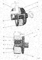
- the rotor assembly shown includes a rotor 12 and a housing closure cap 20 in which the rotor 12 is rotatably anchored.
- the rotor has drive vanes 56, 58, 60 and 62.
- the drive vanes 56, 58 and 60, 62 are connected to each other via two annular arcs at each end. In this way, in particular, stabilization of the drive vanes can be achieved.
- centrifugal forces are acting when the rotor rotates, which drives the fluid outwards, ie in the direction of the rotor periphery.
- the asymmetrical application of force leads to high wear on the assembly.
- an exemplary rotor assembly according to the invention is shown schematically. It comprises a rotor 13 and a housing sealing cap 20.
- the rotor 13 has a hub 54 which is slid onto the rotor axis and from which four identical drive vanes 55, 57, 59, 61 protrude, which are arranged evenly around the hub.
- the drive vanes have an extension D in the axial direction (i.e. in a direction parallel to the rotor axis).
- the hub 54 protrudes by the length d beyond the corresponding side edges of the drive vanes.
- the drive vanes 55, 57, 59, 61 are spaced apart from the housing closure cap 20 and a fluid passage of width d (in the direction parallel to the rotor axis) is created without an additional spacer ring having to be used between the housing closure cap 20 and rotor 13.
- An annular material recess 9 is created between the drive vanes and the housing sealing cap 20 around the rotor axis, which enables fluid to flow through. Fluid sucked in as a result of the centrifugal displacement can flow into the rotor 13 from both sides, which reduces wear on the parts used.
- FIG 3 shows an exemplary rotor assembly according to the invention in an exploded view.
- the housing sealing cap 20 is designed to close a rotor housing in a flow meter. It comprises two radially opposite stops 27, 28, which are designed like ears and each have a frontal stop surface 30, 32 for limiting an axial installation position of the rotor 12 in the housing.
- the housing closure cap 20 has a plate-like gripping element 38 which extends between the stops 27, 28.
- the housing sealing cap 20 has a peripheral groove 40 for receiving a sealing ring 21.
- drive vanes 56, 58 and 60 visible.
- the rotor axis 18 of the rotor 12 is according to figure 3 provided at both ends with an annular locking groove 42, 44.
- the housing sealing cap 20 facing (in the illustration of figure 3 right) locking groove 42 dips into a corresponding counter-element of the housing closure cap 20, as a result of which the rotor axis 18 is anchored in the housing closure cap 20 in a form-fitting manner.
- the one facing away from the housing sealing cap (as shown in figure 3 Left) locking groove 44 interacts with a locking ring 46 to be pushed onto the axis of rotation 18, by means of which the rotor 12 is secured on the rotor axis 18 in the axial direction.
- a spacer 48 is arranged between the rotor and the retaining ring in the illustrated embodiment.
- a spacer ring 50 is arranged between the rotor 18 and the housing closure cap 20 and creates a distance between the rotor 12 and the housing closure cap 20 .
- there is an annular material recess around the spacer ring 50 which forms a fluid passage between the drive vanes of the rotor and the housing closure cap 20 . If fluid is driven outwards in the rotating rotor 12 by the centrifugal force, fluid can thus be sucked in on the side of the rotor 12 facing the housing closure cap 20 .
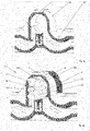
- FIG. 4a and 4b is a sectional view of a housing 23 integrated into a fluid line 2 of a flow meter 1, with the rotor assembly inserted in FIG Figure 4b and without the rotor assembly in Figure 4a .
- fluid flows in the direction indicated by the arrows into the housing 23 where it passes around the rotor axis 18 before exiting the housing and continuing in the direction of the arrow.
- the flow meter has a sensor unit 14 for detecting the rotation of the rotor.
- the amount of fluid that has flowed through can be deduced from its speed.
- the rotor assembly used has a housing sealing cap 20 which, in the perspective shown, closes the housing at the rear thereof. Not shown is the housing base arranged on the opposite side, which closes off the housing on the front side in the perspective shown.
- the rotor assembly comprises a rotor 12 having a hub 51 slid onto the rotor axle 18 and from which four similar drive vanes project; only the drive vanes 56, 58 and 60 can be seen in the illustration.
- the hub protrudes beyond the side edges of the drive vanes facing the housing closure cap, in particular beyond the side edge 58a of the drive vane 58, so that a fluid passage is present at this point.
- annular material recess 9 between the drive vanes and the housing closure cap, which enables a fluid flow between the drive vanes and closure cap and laterally into the rotor.
- a rotor assembly for a flow meter for measuring a fluid flow in a fluid line comprising a rotor which is mounted on a housing closure cap so as to be rotatable about a rotor axis and has at least one drive vane protruding radially from the rotor axis.
- a fluid passage is arranged between the at least one drive vane and the housing closure cap.
- a flow meter having a rotor with at least one drive vane and a housing in which the rotor is arranged axially between two housing walls. There is a fluid passage between the at least one drive vane and each housing wall. Also disclosed is a rotor for such a rotor assembly and/or for such a flow meter, as well as a water-bearing household appliance with a flow meter.
Landscapes
- Physics & Mathematics (AREA)
- Electromagnetism (AREA)
- Fluid Mechanics (AREA)
- General Physics & Mathematics (AREA)
- Measuring Volume Flow (AREA)
Claims (10)
- Ensemble de rotor (3) pour un débitmètre (1) pour la mesure d'un débit de fluide dans une conduite de fluide (2), l'ensemble de rotor comprenant un rotor (12, 13), qui est monté de manière rotative autour d'un axe de rotor (18) sur un capuchon de fermeture de boîtier (20) et présente au moins une ailette d'entraînement (56, 57, 58, 59) en saillie radialement à partir de l'axe de rotor, un passage de fluide étant agencé entre l'au moins une ailette d'entraînement et le capuchon de fermeture de boîtier, le rotor (12, 13) étant moulé en une matière plastique, caractérisé en ce que le rotor (12, 13) est entièrement ou partiellement revêtu d'un matériau à aimantation permanente ou électriquement conducteur.
- Ensemble de rotor selon la revendication 1, dans lequel le rotor (12, 13) présente deux ailettes d'entraînement ou plus (56, 57, 58, 59) en saillie radialement à partir de l'axe de rotor, qui sont espacées du capuchon de fermeture de boîtier (20) de telle sorte qu'un évidement de matériau annulaire (9) entre les ailettes d'entraînement et le capuchon de fermeture de boîtier autour de l'axe de rotor (18) permet un écoulement de fluide.
- Ensemble de rotor selon l'une quelconque des revendications précédentes, dans lequel le passage de fluide a une étendue (d) dans la direction parallèle à l'axe de rotor (18) qui est d'au moins 1/8, de manière davantage préférée d'au moins 1/6 ou d'au moins 1/4 d'une étendue (D) de l'au moins une ailette d'entraînement dans la direction axiale.
- Ensemble de rotor selon l'une quelconque des revendications 1 à 3, dans lequel le passage de fluide est un premier passage de fluide et le rotor (12, 13) est adapté pour être inséré dans un boîtier (23) formé dans une section de la conduite de fluide (2) à travers la paroi de celui-ci, de telle sorte que le rotor est agencé dans le boîtier entre le capuchon de fermeture de boîtier (20) et un fond de boîtier opposé à celui-ci, un deuxième passage de fluide étant situé entre le fond de boîtier et l'au moins une ailette d'entraînement (56, 57, 58, 59), et le premier et le deuxième passage de fluide ayant des dimensions essentiellement égales.
- Ensemble de rotor selon l'une quelconque des revendications précédentes, dans lequel le rotor présente un moyeu (51) qui, dans une direction parallèle à l'axe de rotor (18), dépasse au moins partiellement au-delà d'un bord latéral (58a) faisant face au capuchon de fermeture de boîtier (20) et/ou au-delà d'un bord latéral de l'au moins une ailette d'entraînement (56, 57, 58, 59) détourné du capuchon de fermeture de boîtier.
- Débitmètre (1) pour la mesure d'un débit de fluide dans une conduite de fluide (2), le débitmètre présentant un rotor (12) ayant au moins une ailette d'entraînement (56, 57, 58, 59) et un boîtier (23) pour le rotor, à travers lequel passe la conduite de fluide, le rotor étant agencé axialement dans le boîtier entre deux parois de boîtier, un passage de fluide (9) étant situé respectivement entre l'au moins une ailette d'entraînement et chaque paroi de boîtier, le rotor (12, 13) étant moulé en une matière plastique, caractérisé en ce que le rotor (12, 13) est entièrement ou partiellement revêtu d'un matériau à aimantation permanente ou électriquement conducteur.
- Débitmètre (1) selon la revendication 6, dans lequel le rotor fait partie d'un ensemble de rotor selon l'une quelconque des revendications 1 à 5.
- Débitmètre selon la revendication 6, dans lequel le rotor présente un moyeu (51) qui, dans une direction parallèle à l'axe de rotor (18), dépasse au moins partiellement au-delà d'un bord latéral (58a) de l'au moins une ailette d'entraînement (56, 57, 58, 59), qui est tourné vers l'une des parois de boîtier.
- Appareil ménager conduisant de l'eau, comprenant un débitmètre (1) selon l'une quelconque des revendications 6 ou 7.
- Rotor (12, 13) pour un ensemble de rotor selon la revendication 5, dans lequel le moyeu (51) est fabriqué d'un seul tenant avec l'au moins une ailette d'entraînement (56, 57, 58, 59).
Applications Claiming Priority (1)
| Application Number | Priority Date | Filing Date | Title |
|---|---|---|---|
| DE102014226444.8A DE102014226444A1 (de) | 2014-12-18 | 2014-12-18 | Rotorbaugruppe, Durchflussmesser, Rotor und wasserführendes Haushaltsgerät |
Publications (2)
| Publication Number | Publication Date |
|---|---|
| EP3035005A1 EP3035005A1 (fr) | 2016-06-22 |
| EP3035005B1 true EP3035005B1 (fr) | 2022-06-01 |
Family
ID=54850002
Family Applications (1)
| Application Number | Title | Priority Date | Filing Date |
|---|---|---|---|
| EP15199291.4A Active EP3035005B1 (fr) | 2014-12-18 | 2015-12-10 | Ensemble rotorique, debitmetre, rotor et appareil transportant de l'eau |
Country Status (2)
| Country | Link |
|---|---|
| EP (1) | EP3035005B1 (fr) |
| DE (1) | DE102014226444A1 (fr) |
Citations (3)
| Publication number | Priority date | Publication date | Assignee | Title |
|---|---|---|---|---|
| EP0121734A1 (fr) * | 1983-03-21 | 1984-10-17 | Socam | Dispositif de mesure de la rotation d'une turbine de compteurs de débit de fluide |
| US6789434B2 (en) * | 2001-10-23 | 2004-09-14 | Dwyer Instruments, Inc. | Fluid flowmeter having a hall effect sensor with an internal magnet |
| WO2012138239A1 (fr) * | 2011-04-07 | 2012-10-11 | Fila, Antoni Polska Fabryka Wodomierzy I Cieplomierzy Fila | Débitmètre de type vitesse à lecture électronique |
Family Cites Families (6)
| Publication number | Priority date | Publication date | Assignee | Title |
|---|---|---|---|---|
| AT409302B (de) * | 1999-03-23 | 2002-07-25 | Vaillant Gmbh | Flügelrad-durchflussmesser |
| AT502408B1 (de) * | 2005-02-21 | 2007-03-15 | Vaillant Gmbh | Wassermengenmesser |
| HUE035324T2 (en) * | 2007-07-19 | 2018-05-02 | Gealan Formteile Gmbh | Flowmeter |
| DE102008035629A1 (de) * | 2007-08-09 | 2009-02-12 | Zucholl, Klaus, Dr. | Durchflußmesser mit Leitwertmessung |
| DE102007060190A1 (de) * | 2007-12-14 | 2009-06-18 | BSH Bosch und Siemens Hausgeräte GmbH | Heizblock für Warmwassergerät |
| DE102009043344A1 (de) * | 2009-09-29 | 2011-03-31 | Aweco Appliance Systems Gmbh & Co. Kg | Oberteil für einen Durchflussmesser, Durchflussmesser sowie Verfahren zur Herstellung eines Oberteils für einen Durchflussmesser |
-
2014
- 2014-12-18 DE DE102014226444.8A patent/DE102014226444A1/de not_active Ceased
-
2015
- 2015-12-10 EP EP15199291.4A patent/EP3035005B1/fr active Active
Patent Citations (3)
| Publication number | Priority date | Publication date | Assignee | Title |
|---|---|---|---|---|
| EP0121734A1 (fr) * | 1983-03-21 | 1984-10-17 | Socam | Dispositif de mesure de la rotation d'une turbine de compteurs de débit de fluide |
| US6789434B2 (en) * | 2001-10-23 | 2004-09-14 | Dwyer Instruments, Inc. | Fluid flowmeter having a hall effect sensor with an internal magnet |
| WO2012138239A1 (fr) * | 2011-04-07 | 2012-10-11 | Fila, Antoni Polska Fabryka Wodomierzy I Cieplomierzy Fila | Débitmètre de type vitesse à lecture électronique |
Also Published As
| Publication number | Publication date |
|---|---|
| EP3035005A1 (fr) | 2016-06-22 |
| DE102014226444A1 (de) | 2016-06-23 |
Similar Documents
| Publication | Publication Date | Title |
|---|---|---|
| EP2495444B1 (fr) | Pompe | |
| EP3008346B1 (fr) | Pompe | |
| EP2377451B1 (fr) | Pompe avec dispositif de chauffage | |
| EP2677178A2 (fr) | Pompe | |
| DE102012000376A1 (de) | Axial- oder Diagonalventilator | |
| EP3880967B1 (fr) | Ventilateur diagonal équipé d'un dispositif directeur de sortie | |
| WO2015169496A1 (fr) | Rotor, en particulier pour une machine à canal latéral | |
| DE1498357A1 (de) | Durchflussmesser | |
| DE202014010710U1 (de) | Querstromströmungspumpe | |
| EP2546525B1 (fr) | Pompe centrifuge dotée d'un boîtier à spirales | |
| EP2754900B1 (fr) | Turbopompe comprenant dispositif de chauffage | |
| EP3035005B1 (fr) | Ensemble rotorique, debitmetre, rotor et appareil transportant de l'eau | |
| EP3184823B1 (fr) | Pompe centrifuge | |
| EP2862494A1 (fr) | Appareil ménager véhiculant de l'eau | |
| DE3415366C2 (fr) | ||
| DE102011004512A1 (de) | Seitenkanal-Maschinen-Anordnung | |
| DE112011101949B4 (de) | Pumpengruppe für einen Kühlkreislauf, insbesondere für ein Motorrad | |
| EP2606235B1 (fr) | Pompe à palettes | |
| DE102008052981A1 (de) | Leitschaufel eines Axialverdichters | |
| EP2835618B1 (fr) | Débitmètre avec un rotor pour un appareil ménager transportant de l'eau | |
| DE202013100271U1 (de) | Durchflussmesseinrichtung für eine Getränkezubereitungsmaschine | |
| DE3108507C2 (fr) | ||
| WO1999039105A1 (fr) | Roue mobile de pompe centrifuge, de structure radiale | |
| DE102013211181B3 (de) | Pumpe | |
| DE102016110224B4 (de) | Kreiselpumpe und Laufrad für eine Kreiselpumpe |
Legal Events
| Date | Code | Title | Description |
|---|---|---|---|
| PUAI | Public reference made under article 153(3) epc to a published international application that has entered the european phase |
Free format text: ORIGINAL CODE: 0009012 |
|
| AK | Designated contracting states |
Kind code of ref document: A1 Designated state(s): AL AT BE BG CH CY CZ DE DK EE ES FI FR GB GR HR HU IE IS IT LI LT LU LV MC MK MT NL NO PL PT RO RS SE SI SK SM TR |
|
| AX | Request for extension of the european patent |
Extension state: BA ME |
|
| STAA | Information on the status of an ep patent application or granted ep patent |
Free format text: STATUS: REQUEST FOR EXAMINATION WAS MADE |
|
| 17P | Request for examination filed |
Effective date: 20161222 |
|
| RBV | Designated contracting states (corrected) |
Designated state(s): AL AT BE BG CH CY CZ DE DK EE ES FI FR GB GR HR HU IE IS IT LI LT LU LV MC MK MT NL NO PL PT RO RS SE SI SK SM TR |
|
| STAA | Information on the status of an ep patent application or granted ep patent |
Free format text: STATUS: EXAMINATION IS IN PROGRESS |
|
| 17Q | First examination report despatched |
Effective date: 20170818 |
|
| RAP1 | Party data changed (applicant data changed or rights of an application transferred) |
Owner name: ROBERT BOSCH GMBH |
|
| RAP1 | Party data changed (applicant data changed or rights of an application transferred) |
Owner name: ROBERT BOSCH GMBH |
|
| GRAP | Despatch of communication of intention to grant a patent |
Free format text: ORIGINAL CODE: EPIDOSNIGR1 |
|
| STAA | Information on the status of an ep patent application or granted ep patent |
Free format text: STATUS: GRANT OF PATENT IS INTENDED |
|
| INTG | Intention to grant announced |
Effective date: 20220107 |
|
| GRAS | Grant fee paid |
Free format text: ORIGINAL CODE: EPIDOSNIGR3 |
|
| GRAA | (expected) grant |
Free format text: ORIGINAL CODE: 0009210 |
|
| STAA | Information on the status of an ep patent application or granted ep patent |
Free format text: STATUS: THE PATENT HAS BEEN GRANTED |
|
| AK | Designated contracting states |
Kind code of ref document: B1 Designated state(s): AL AT BE BG CH CY CZ DE DK EE ES FI FR GB GR HR HU IE IS IT LI LT LU LV MC MK MT NL NO PL PT RO RS SE SI SK SM TR |
|
| REG | Reference to a national code |
Ref country code: GB Ref legal event code: FG4D Free format text: NOT ENGLISH |
|
| REG | Reference to a national code |
Ref country code: AT Ref legal event code: REF Ref document number: 1495668 Country of ref document: AT Kind code of ref document: T Effective date: 20220615 Ref country code: CH Ref legal event code: EP |
|
| REG | Reference to a national code |
Ref country code: IE Ref legal event code: FG4D Free format text: LANGUAGE OF EP DOCUMENT: GERMAN |
|
| REG | Reference to a national code |
Ref country code: DE Ref legal event code: R096 Ref document number: 502015015871 Country of ref document: DE |
|
| REG | Reference to a national code |
Ref country code: LT Ref legal event code: MG9D |
|
| REG | Reference to a national code |
Ref country code: NL Ref legal event code: MP Effective date: 20220601 |
|
| PG25 | Lapsed in a contracting state [announced via postgrant information from national office to epo] |
Ref country code: SE Free format text: LAPSE BECAUSE OF FAILURE TO SUBMIT A TRANSLATION OF THE DESCRIPTION OR TO PAY THE FEE WITHIN THE PRESCRIBED TIME-LIMIT Effective date: 20220601 Ref country code: NO Free format text: LAPSE BECAUSE OF FAILURE TO SUBMIT A TRANSLATION OF THE DESCRIPTION OR TO PAY THE FEE WITHIN THE PRESCRIBED TIME-LIMIT Effective date: 20220901 Ref country code: LT Free format text: LAPSE BECAUSE OF FAILURE TO SUBMIT A TRANSLATION OF THE DESCRIPTION OR TO PAY THE FEE WITHIN THE PRESCRIBED TIME-LIMIT Effective date: 20220601 Ref country code: HR Free format text: LAPSE BECAUSE OF FAILURE TO SUBMIT A TRANSLATION OF THE DESCRIPTION OR TO PAY THE FEE WITHIN THE PRESCRIBED TIME-LIMIT Effective date: 20220601 Ref country code: GR Free format text: LAPSE BECAUSE OF FAILURE TO SUBMIT A TRANSLATION OF THE DESCRIPTION OR TO PAY THE FEE WITHIN THE PRESCRIBED TIME-LIMIT Effective date: 20220902 Ref country code: FI Free format text: LAPSE BECAUSE OF FAILURE TO SUBMIT A TRANSLATION OF THE DESCRIPTION OR TO PAY THE FEE WITHIN THE PRESCRIBED TIME-LIMIT Effective date: 20220601 Ref country code: ES Free format text: LAPSE BECAUSE OF FAILURE TO SUBMIT A TRANSLATION OF THE DESCRIPTION OR TO PAY THE FEE WITHIN THE PRESCRIBED TIME-LIMIT Effective date: 20220601 Ref country code: BG Free format text: LAPSE BECAUSE OF FAILURE TO SUBMIT A TRANSLATION OF THE DESCRIPTION OR TO PAY THE FEE WITHIN THE PRESCRIBED TIME-LIMIT Effective date: 20220901 |
|
| PG25 | Lapsed in a contracting state [announced via postgrant information from national office to epo] |
Ref country code: RS Free format text: LAPSE BECAUSE OF FAILURE TO SUBMIT A TRANSLATION OF THE DESCRIPTION OR TO PAY THE FEE WITHIN THE PRESCRIBED TIME-LIMIT Effective date: 20220601 Ref country code: PL Free format text: LAPSE BECAUSE OF FAILURE TO SUBMIT A TRANSLATION OF THE DESCRIPTION OR TO PAY THE FEE WITHIN THE PRESCRIBED TIME-LIMIT Effective date: 20220601 Ref country code: LV Free format text: LAPSE BECAUSE OF FAILURE TO SUBMIT A TRANSLATION OF THE DESCRIPTION OR TO PAY THE FEE WITHIN THE PRESCRIBED TIME-LIMIT Effective date: 20220601 |
|
| REG | Reference to a national code |
Ref country code: FR Ref legal event code: PLFP Year of fee payment: 8 |
|
| PG25 | Lapsed in a contracting state [announced via postgrant information from national office to epo] |
Ref country code: NL Free format text: LAPSE BECAUSE OF FAILURE TO SUBMIT A TRANSLATION OF THE DESCRIPTION OR TO PAY THE FEE WITHIN THE PRESCRIBED TIME-LIMIT Effective date: 20220601 |
|
| PG25 | Lapsed in a contracting state [announced via postgrant information from national office to epo] |
Ref country code: SM Free format text: LAPSE BECAUSE OF FAILURE TO SUBMIT A TRANSLATION OF THE DESCRIPTION OR TO PAY THE FEE WITHIN THE PRESCRIBED TIME-LIMIT Effective date: 20220601 Ref country code: SK Free format text: LAPSE BECAUSE OF FAILURE TO SUBMIT A TRANSLATION OF THE DESCRIPTION OR TO PAY THE FEE WITHIN THE PRESCRIBED TIME-LIMIT Effective date: 20220601 Ref country code: RO Free format text: LAPSE BECAUSE OF FAILURE TO SUBMIT A TRANSLATION OF THE DESCRIPTION OR TO PAY THE FEE WITHIN THE PRESCRIBED TIME-LIMIT Effective date: 20220601 Ref country code: PT Free format text: LAPSE BECAUSE OF FAILURE TO SUBMIT A TRANSLATION OF THE DESCRIPTION OR TO PAY THE FEE WITHIN THE PRESCRIBED TIME-LIMIT Effective date: 20221003 Ref country code: EE Free format text: LAPSE BECAUSE OF FAILURE TO SUBMIT A TRANSLATION OF THE DESCRIPTION OR TO PAY THE FEE WITHIN THE PRESCRIBED TIME-LIMIT Effective date: 20220601 Ref country code: CZ Free format text: LAPSE BECAUSE OF FAILURE TO SUBMIT A TRANSLATION OF THE DESCRIPTION OR TO PAY THE FEE WITHIN THE PRESCRIBED TIME-LIMIT Effective date: 20220601 |
|
| PG25 | Lapsed in a contracting state [announced via postgrant information from national office to epo] |
Ref country code: IS Free format text: LAPSE BECAUSE OF FAILURE TO SUBMIT A TRANSLATION OF THE DESCRIPTION OR TO PAY THE FEE WITHIN THE PRESCRIBED TIME-LIMIT Effective date: 20221001 |
|
| REG | Reference to a national code |
Ref country code: DE Ref legal event code: R097 Ref document number: 502015015871 Country of ref document: DE |
|
| PG25 | Lapsed in a contracting state [announced via postgrant information from national office to epo] |
Ref country code: AL Free format text: LAPSE BECAUSE OF FAILURE TO SUBMIT A TRANSLATION OF THE DESCRIPTION OR TO PAY THE FEE WITHIN THE PRESCRIBED TIME-LIMIT Effective date: 20220601 |
|
| PLBE | No opposition filed within time limit |
Free format text: ORIGINAL CODE: 0009261 |
|
| STAA | Information on the status of an ep patent application or granted ep patent |
Free format text: STATUS: NO OPPOSITION FILED WITHIN TIME LIMIT |
|
| PG25 | Lapsed in a contracting state [announced via postgrant information from national office to epo] |
Ref country code: DK Free format text: LAPSE BECAUSE OF FAILURE TO SUBMIT A TRANSLATION OF THE DESCRIPTION OR TO PAY THE FEE WITHIN THE PRESCRIBED TIME-LIMIT Effective date: 20220601 |
|
| 26N | No opposition filed |
Effective date: 20230302 |
|
| PG25 | Lapsed in a contracting state [announced via postgrant information from national office to epo] |
Ref country code: SI Free format text: LAPSE BECAUSE OF FAILURE TO SUBMIT A TRANSLATION OF THE DESCRIPTION OR TO PAY THE FEE WITHIN THE PRESCRIBED TIME-LIMIT Effective date: 20220601 |
|
| REG | Reference to a national code |
Ref country code: CH Ref legal event code: PL |
|
| REG | Reference to a national code |
Ref country code: BE Ref legal event code: MM Effective date: 20221231 |
|
| PG25 | Lapsed in a contracting state [announced via postgrant information from national office to epo] |
Ref country code: LU Free format text: LAPSE BECAUSE OF NON-PAYMENT OF DUE FEES Effective date: 20221210 |
|
| PG25 | Lapsed in a contracting state [announced via postgrant information from national office to epo] |
Ref country code: LI Free format text: LAPSE BECAUSE OF NON-PAYMENT OF DUE FEES Effective date: 20221231 Ref country code: IE Free format text: LAPSE BECAUSE OF NON-PAYMENT OF DUE FEES Effective date: 20221210 Ref country code: CH Free format text: LAPSE BECAUSE OF NON-PAYMENT OF DUE FEES Effective date: 20221231 |
|
| PG25 | Lapsed in a contracting state [announced via postgrant information from national office to epo] |
Ref country code: BE Free format text: LAPSE BECAUSE OF NON-PAYMENT OF DUE FEES Effective date: 20221231 |
|
| PG25 | Lapsed in a contracting state [announced via postgrant information from national office to epo] |
Ref country code: IT Free format text: LAPSE BECAUSE OF FAILURE TO SUBMIT A TRANSLATION OF THE DESCRIPTION OR TO PAY THE FEE WITHIN THE PRESCRIBED TIME-LIMIT Effective date: 20220601 |
|
| REG | Reference to a national code |
Ref country code: AT Ref legal event code: MM01 Ref document number: 1495668 Country of ref document: AT Kind code of ref document: T Effective date: 20221210 |
|
| PG25 | Lapsed in a contracting state [announced via postgrant information from national office to epo] |
Ref country code: HU Free format text: LAPSE BECAUSE OF FAILURE TO SUBMIT A TRANSLATION OF THE DESCRIPTION OR TO PAY THE FEE WITHIN THE PRESCRIBED TIME-LIMIT; INVALID AB INITIO Effective date: 20151210 |
|
| PG25 | Lapsed in a contracting state [announced via postgrant information from national office to epo] |
Ref country code: AT Free format text: LAPSE BECAUSE OF NON-PAYMENT OF DUE FEES Effective date: 20221210 |
|
| PG25 | Lapsed in a contracting state [announced via postgrant information from national office to epo] |
Ref country code: CY Free format text: LAPSE BECAUSE OF FAILURE TO SUBMIT A TRANSLATION OF THE DESCRIPTION OR TO PAY THE FEE WITHIN THE PRESCRIBED TIME-LIMIT Effective date: 20220601 Ref country code: AT Free format text: LAPSE BECAUSE OF NON-PAYMENT OF DUE FEES Effective date: 20221210 |
|
| PG25 | Lapsed in a contracting state [announced via postgrant information from national office to epo] |
Ref country code: MK Free format text: LAPSE BECAUSE OF FAILURE TO SUBMIT A TRANSLATION OF THE DESCRIPTION OR TO PAY THE FEE WITHIN THE PRESCRIBED TIME-LIMIT Effective date: 20220601 |
|
| PG25 | Lapsed in a contracting state [announced via postgrant information from national office to epo] |
Ref country code: MC Free format text: LAPSE BECAUSE OF FAILURE TO SUBMIT A TRANSLATION OF THE DESCRIPTION OR TO PAY THE FEE WITHIN THE PRESCRIBED TIME-LIMIT Effective date: 20220601 |
|
| PG25 | Lapsed in a contracting state [announced via postgrant information from national office to epo] |
Ref country code: TR Free format text: LAPSE BECAUSE OF FAILURE TO SUBMIT A TRANSLATION OF THE DESCRIPTION OR TO PAY THE FEE WITHIN THE PRESCRIBED TIME-LIMIT Effective date: 20220601 Ref country code: MC Free format text: LAPSE BECAUSE OF FAILURE TO SUBMIT A TRANSLATION OF THE DESCRIPTION OR TO PAY THE FEE WITHIN THE PRESCRIBED TIME-LIMIT Effective date: 20220601 |
|
| PG25 | Lapsed in a contracting state [announced via postgrant information from national office to epo] |
Ref country code: MT Free format text: LAPSE BECAUSE OF FAILURE TO SUBMIT A TRANSLATION OF THE DESCRIPTION OR TO PAY THE FEE WITHIN THE PRESCRIBED TIME-LIMIT Effective date: 20220601 |
|
| PG25 | Lapsed in a contracting state [announced via postgrant information from national office to epo] |
Ref country code: BG Free format text: LAPSE BECAUSE OF FAILURE TO SUBMIT A TRANSLATION OF THE DESCRIPTION OR TO PAY THE FEE WITHIN THE PRESCRIBED TIME-LIMIT Effective date: 20220601 |
|
| PG25 | Lapsed in a contracting state [announced via postgrant information from national office to epo] |
Ref country code: BG Free format text: LAPSE BECAUSE OF FAILURE TO SUBMIT A TRANSLATION OF THE DESCRIPTION OR TO PAY THE FEE WITHIN THE PRESCRIBED TIME-LIMIT Effective date: 20220601 |
|
| PGFP | Annual fee paid to national office [announced via postgrant information from national office to epo] |
Ref country code: GB Payment date: 20251218 Year of fee payment: 11 |
|
| PGFP | Annual fee paid to national office [announced via postgrant information from national office to epo] |
Ref country code: FR Payment date: 20251218 Year of fee payment: 11 |
|
| PGFP | Annual fee paid to national office [announced via postgrant information from national office to epo] |
Ref country code: DE Payment date: 20260223 Year of fee payment: 11 |