EP3035019B1 - Statorschlitztemperatursensor und montageverfahren dafür - Google Patents
Statorschlitztemperatursensor und montageverfahren dafür Download PDFInfo
- Publication number
- EP3035019B1 EP3035019B1 EP15200008.9A EP15200008A EP3035019B1 EP 3035019 B1 EP3035019 B1 EP 3035019B1 EP 15200008 A EP15200008 A EP 15200008A EP 3035019 B1 EP3035019 B1 EP 3035019B1
- Authority
- EP
- European Patent Office
- Prior art keywords
- lead wire
- temperature sensor
- sensor assembly
- stator slot
- wiring pattern
- Prior art date
- Legal status (The legal status is an assumption and is not a legal conclusion. Google has not performed a legal analysis and makes no representation as to the accuracy of the status listed.)
- Active
Links
Images
Classifications
-
- G—PHYSICS
- G01—MEASURING; TESTING
- G01K—MEASURING TEMPERATURE; MEASURING QUANTITY OF HEAT; THERMALLY-SENSITIVE ELEMENTS NOT OTHERWISE PROVIDED FOR
- G01K1/00—Details of thermometers not specially adapted for particular types of thermometer
- G01K1/14—Supports; Fastening devices; Arrangements for mounting thermometers in particular locations
-
- G—PHYSICS
- G01—MEASURING; TESTING
- G01K—MEASURING TEMPERATURE; MEASURING QUANTITY OF HEAT; THERMALLY-SENSITIVE ELEMENTS NOT OTHERWISE PROVIDED FOR
- G01K7/00—Measuring temperature based on the use of electric or magnetic elements directly sensitive to heat ; Power supply therefor, e.g. using thermoelectric elements
- G01K7/16—Measuring temperature based on the use of electric or magnetic elements directly sensitive to heat ; Power supply therefor, e.g. using thermoelectric elements using resistive elements
- G01K7/18—Measuring temperature based on the use of electric or magnetic elements directly sensitive to heat ; Power supply therefor, e.g. using thermoelectric elements using resistive elements the element being a linear resistance, e.g. platinum resistance thermometer
-
- H—ELECTRICITY
- H05—ELECTRIC TECHNIQUES NOT OTHERWISE PROVIDED FOR
- H05K—PRINTED CIRCUITS; CASINGS OR CONSTRUCTIONAL DETAILS OF ELECTRIC APPARATUS; MANUFACTURE OF ASSEMBLAGES OF ELECTRICAL COMPONENTS
- H05K1/00—Printed circuits
- H05K1/18—Printed circuits structurally associated with non-printed electric components
- H05K1/182—Printed circuits structurally associated with non-printed electric components associated with components mounted in printed circuit boards [PCB], e.g. insert-mounted components [IMC]
- H05K1/185—Printed circuits structurally associated with non-printed electric components associated with components mounted in printed circuit boards [PCB], e.g. insert-mounted components [IMC] associated with components encapsulated in the insulating substrate of the PCBs; associated with components incorporated in internal layers of multilayer circuit boards
-
- G—PHYSICS
- G01—MEASURING; TESTING
- G01K—MEASURING TEMPERATURE; MEASURING QUANTITY OF HEAT; THERMALLY-SENSITIVE ELEMENTS NOT OTHERWISE PROVIDED FOR
- G01K1/00—Details of thermometers not specially adapted for particular types of thermometer
- G01K1/08—Protective devices, e.g. casings
-
- G—PHYSICS
- G01—MEASURING; TESTING
- G01K—MEASURING TEMPERATURE; MEASURING QUANTITY OF HEAT; THERMALLY-SENSITIVE ELEMENTS NOT OTHERWISE PROVIDED FOR
- G01K7/00—Measuring temperature based on the use of electric or magnetic elements directly sensitive to heat ; Power supply therefor, e.g. using thermoelectric elements
- G01K7/16—Measuring temperature based on the use of electric or magnetic elements directly sensitive to heat ; Power supply therefor, e.g. using thermoelectric elements using resistive elements
-
- H—ELECTRICITY
- H02—GENERATION; CONVERSION OR DISTRIBUTION OF ELECTRIC POWER
- H02K—DYNAMO-ELECTRIC MACHINES
- H02K11/00—Structural association of dynamo-electric machines with electric components or with devices for shielding, monitoring or protection
-
- H—ELECTRICITY
- H05—ELECTRIC TECHNIQUES NOT OTHERWISE PROVIDED FOR
- H05K—PRINTED CIRCUITS; CASINGS OR CONSTRUCTIONAL DETAILS OF ELECTRIC APPARATUS; MANUFACTURE OF ASSEMBLAGES OF ELECTRICAL COMPONENTS
- H05K3/00—Apparatus or processes for manufacturing printed circuits
- H05K3/0011—Working of insulating substrates or insulating layers
-
- H—ELECTRICITY
- H05—ELECTRIC TECHNIQUES NOT OTHERWISE PROVIDED FOR
- H05K—PRINTED CIRCUITS; CASINGS OR CONSTRUCTIONAL DETAILS OF ELECTRIC APPARATUS; MANUFACTURE OF ASSEMBLAGES OF ELECTRICAL COMPONENTS
- H05K2201/00—Indexing scheme relating to printed circuits covered by H05K1/00
- H05K2201/10—Details of components or other objects attached to or integrated in a printed circuit board
- H05K2201/10613—Details of electrical connections of non-printed components, e.g. special leads
- H05K2201/10742—Details of leads
- H05K2201/1075—Shape details
- H05K2201/10757—Bent leads
Definitions
- the present invention relates to a stator slot temperature sensor assembly and a method of manufacturing the same and, more particularly, to a stator slot temperature sensor assembly including a flexible substrate and a laminate slot and a method of manufacturing the same.
- the slot of the stator core of a power generator includes a temperature sensor for continuously monitoring the state in order to prevent overheating or a undesirable state.
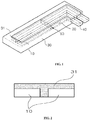
- FIG. 1a is a perspective view of a conventional stator slot temperature sensor assembly
- FIG. 1b is a cross-sectional view of the conventional stator slot temperature sensor assembly.
- a temperature sensor is formed between the top bar and bottom bar of a stator slot.
- the temperature sensor is a sensing resistor (RTD), and includes an element made of platinum and configured to have resistance changing depending on a temperature, a pair of parallel lead wires connected to the element, a laminate configured to mechanically protect and surround the element and the lead wire, and a lead wire drawn out part extended and protruded from the lead wire to the outside of the laminate.
- RTD sensing resistor
- the laminate is received in the element.
- a pair of the elements is received in a single slot in parallel, and resin is attached to the top thereof.
- the lead wire is extended to the lead wire drawn out part which is curved from one end of the laminate at 90 degrees and drawn.
- the lead wire and the element are coupled by soldering. Furthermore, the drawn out part and an external conducting wire connected to an external circuit are coupled by soldering.
- the conventional temperature sensor has a problem in that external pressure is applied when the temperature sensor is placed and assembled between the top bar and bottom bar of the stator slot and the external pressure is applied to the element or the lead wire, resulting in disconnection.
- Major causes of such disconnection may include disconnection occurring because the structure of the laminate and the resin forming the laminate is inefficient to protect the element or the lead wire, the disconnection of the lead wire generated due to the external pressure if the soldering is excessive, and disconnection attributable to a reduction of mechanical strength occurring because the lead wire extended to the drawn out part is subject to an excessive amount of bending, for example, when the lead wire is bent 90 degrees.
- DE 10 2011 008 179 A1 discloses a temperature sensor with at least one electronic temperature sensor.
- the electronic temperature sensor is connected to two sensor lines which are led out of the electronic temperature sensor through the suspension and out of the latter and are enclosed outside the suspension for electrical insulation in a ceramic insulation jacket.
- US 2007/0132541 A1 discloses a thermistor element unit with a lead conductor and a terminal plate welded outside a plate portion thereof to a distal end of the lead conductor.
- the lead conductors are curved to provide each intermediate portion with at least one bend.
- the terminal plate and the distal end of the lead conductor are welded together, so that these components are joined together with a weld in an alloyed state.
- Embodiments of the present disclosure are directed to solving the problems of the conventional stator slot temperature sensor assembly and a method of manufacturing the same by improving the shape of a laminate, mediating a connection unit between lead wires or between a lead wire and an element using a flexible substrate, and changing the angle of a lead wire extended to a drawn out part.
- a stator slot temperature sensor assembly which is placed between a plurality of stator coils stacked in a stator slot and comprises an element, a lead wire connected to the element, a laminate configured to surround the element and the lead wire, and a lead wire drawn out part extended and protruded from the lead wire to the outside of the laminate.
- the laminate may comprise element slots respectively configured to accommodate a pair of the elements and lead wire slots extended from the element slots and respectively configured to accommodate the pair of lead wires.
- the element may be pressed in the element slot.
- Resin for fixing the element may be disposed over the element.
- the lead wire may be pressed in the lead wire slot.
- the resin for fixing the lead wire may be disposed over the lead wire.
- the element and the lead wire is coupled through the medium of a flexible substrate.
- lead wire drawn out part and an external conducting wire connected to an external circuit may be coupled through the medium of the flexible substrate.
- the lead wire may have curvature and may be extended to the lead wire drawing unit.
- the curvature may be 5 mm to 15 mm.
- the internal angle ⁇ of a portion in which the lead wire comes in contact with the drawn out part may be more than 90 degrees and less than 180 degrees.
- a pair of the elements having resistance changing depending on a temperature may be configured.
- the element and the lead wire may be coupled through the medium of a flexible substrate.
- the flexible substrate may comprise a wiring pattern in which the element and the lead wire are coupled on a surface of an insulating base.
- the lead wire drawn out part and an external conducting wire connected to an external circuit may be coupled through the medium of the flexible substrate.
- the flexible substrate may comprise a wiring pattern in which the element and the lead wire are coupled on a surface of an insulating base.
- the element and the lead wire may be coupled through the medium of the flexible substrate.
- the flexible substrate may comprise a wiring pattern in which the element and the lead wire are coupled on a surface of the insulating base.
- An insulating film may be attached on a surface of the wiring pattern.
- the lead wire drawn out part and an external conducting wire connected to an external circuit may be coupled through the medium of the flexible substrate.
- the flexible substrate may comprise a wiring pattern in which the element and the lead wire are coupled on a surface of an insulating base.
- An insulating film may be attached on a surface of the wiring pattern.
- the element and the lead wire may be coupled through the medium of a flexible substrate.
- the flexible substrate may comprise a flexible printed circuit board
- the flexible substrate may comprise a wiring pattern in which the element and the lead wire are coupled on a surface of an insulating base, and etching holes for preventing disconnection of the wiring pattern attributable to a tensile load may be formed in the wiring pattern.
- the flexible substrate may comprise a flexible printed circuit board, the flexible substrate may comprise a wiring pattern in which the element and the lead wire are coupled on a surface of an insulating base, and etching holes for preventing disconnection of the wiring pattern attributable to a tensile load may be formed in the wiring pattern.
- a method of manufacturing a stator slot temperature sensor assembly comprise a first step of processing an element slot and a lead wire slot in a laminate in the length direction of a base and a second step of matching up the element with the element slot, matching up the lead wire with the lead wire slot, and attaching resin on top of the element and on top of the lead wire.
- the second step may comprise connecting the element to a terminal at the first end of the wiring pattern of a flexible printed circuit board by soldering and connecting the lead wire to a terminal at the second end of a wiring pattern of the flexible printed circuit board by soldering.
- the flexible substrate may be fabricated by processing polymer in an insulating base, stacking electrolytic copper foils on top of the insulating base by pressurization and heating with an adhesive layer interposed between the electrolytic copper foils and the insulating base and processing the wiring pattern comprise etching holes by etching using photolithography, and attaching an insulating film on top of the wiring pattern other than the terminals.
- the first step may comprise forming the internal angle of a section communicating with the outside of the laminate of the lead wire slot and the laminate so that the internal angle is more than 90 degrees and less than 180 degrees.
- the first step may comprise forming a section communicating with the outside of the laminate of the lead wire slot so that the section has curvature.
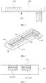
- FIG. 3 is a plan view of a stator slot temperature sensor assembly in accordance with an embodiment of the present disclosure
- FIG. 4 is a perspective view of the stator slot temperature sensor assembly in accordance with an embodiment of the present disclosure.
- FIG. 5 is a cross-sectional view on the side of an element of the stator slot temperature sensor assembly in accordance with an embodiment of the present disclosure.
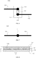
- FIG. 6 is a schematic diagram showing the state in which a lead wire and an element are coupled in accordance with an embodiment of the present disclosure.
- FIG. 7 is a schematic diagram showing the state in which a lead wire and an element are coupled in accordance with an example not according to the invention.
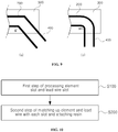
- FIG. 8 shows the side of the flexible substrate of the stator slot temperature sensor assembly in accordance with an embodiment of the present disclosure.
- FIG. 9 shows the drawn out part of the stator slot temperature sensor assembly in accordance with an embodiment of the present disclosure.
- the stator slot temperature sensor assembly in accordance with an embodiment of the present disclosure comprises elements 100 that are sensing resistors, lead wires 200, a laminate 300, and lead wire drawn out parts 400.
- the stator slot temperature sensor assembly may comprise internal conductors and external conductors in lieu of the lead wires 200 and the lead wire drawn out parts 400.
- the element 100 is made of a material having resistance changing depending on a temperature.
- the element 100 may be made of platinum.
- a pair of the lead wires 200 is arranged in parallel in the length direction thereof and connected to the elements 100.
- the pair of lead wires 200 functions to connect the element 100 to an external circuit capable of measuring the value of the resistance.
- the laminate 300 functions to surround the element 100 and the lead wires 200.
- the lead wire drawn out parts 400 are extended and protruded from the lead wire 200 to the outside of the laminate 300.
- the laminate 300 may comprise element slots 310 respectively configured to accommodate a pair of the elements 100 and lead wire slots 320 respectively extended from the element slots 310 and configured to accommodate the pair of lead wires 200.
- the elements 100 are pressed in the element slots 310. Resin 330 for fixing the elements 100 may be disposed on top of the elements 100.
- the lead wires 200 are pressed in the lead wire slots 320. The resin 330 for fixing the lead wires 200 may be disposed on top of the lead wires 200.
- stator slot temperature sensor assembly Unlike in a conventional stator slot temperature sensor assembly, disconnection can be minimized between the lead wire 200 and the element 100 attributable to pressure applied when the lead wires 200 are assembled with the respective lead wire slots 320, the elements 100 are assembled with the respective element slots 310, and the stator slot temperature sensor assembly is assembled between stator coils (not shown).
- the element 100 and the lead wire 200 are coupled based on a connection unit 500.
- the connection unit 500 the element 100 and the lead wire 200 may be directly coupled through soldering 11.
- the element 100 and the lead wire 200 may be coupled through the medium of a flexible substrate 150.
- FIGS. 6 and 7 are schematic diagrams for illustrating a method of coupling the lead wire and the element.
- the coupling of the element 100 and the lead wire 200 in the connection unit 500 is schematically shown based on FIGS. 3 and 4 .
- the element 100 and the lead wire 200 may be coupled together through the medium of the flexible substrate 150.
- the lead wire drawn out part 400 and an external conducting wire connected to an external circuit may be coupled together through the medium of the flexible substrate 150.
- the flexible substrate 150 is a flexible printed circuit board, and comprises a wiring pattern 153 configured to have the element 100 and the lead wire 200 coupled on a surface of an insulating base 151 and an insulating film 154 attached to a surface of the wiring pattern 153.
- Holes 153a for preventing the disconnection of the wiring pattern 153 attributable to a tensile load may be formed in the wiring pattern 153.
- the holes 153a may be formed using various methods, such as etching.
- Holes 153a may be formed with a diameter d.
- a foil 152 may be stacked on the insulating base 151 with an adhesive layer interposed between the foil and the insulating base 151.
- the foil 152 may be, for example, an electrolytic copper foil.
- the soldering part of a conventional stator slot temperature sensor assembly can be prevented from being frequently disconnected.
- Coupling using a common flexible printed circuit board itself has some advantage in that it can prevent the disconnection of the wiring pattern 153.
- the wiring pattern 153 is easily increased when a tensile load is applied to the wiring pattern 153 because the fine holes 153a are formed in the wiring pattern 153.
- the wiring pattern 153 is not cracked when it is deformed because a tensile load is repeatedly applied to the wiring pattern 153 or the wiring pattern 153 is extended to a specific range, but replaces the mechanical strength of soldering between the lead wires 200 or the soldering of the lead wire 200 and the element 100, thereby being capable of preventing disconnection.
- the lead wire 200 may have curvature R and may be extended to the lead wire drawn out part 400.
- the radius of curvature may be set to lie within a range, wherein the range is from 5 mm to 15 mm. In an exemplary embodiment the range is about 5 mm to about 15 mm.
- an internal angle ⁇ of a portion in which the lead wire 200 comes in contact with the lead wire drawn out part 400 may be set to lie within a range, wherein the internal angle ⁇ is in a range of more than 90 degrees and less than 180 degrees.
- a pair of the elements 100 may be configured to have resistance changing depending on a temperature.
- the element 100 and the lead wire 200 may be coupled through the medium of the flexible substrate 150.
- the flexible substrate 150 may be equipped with a wiring pattern in which the element 100 and the lead wire 200 are coupled on a surface of an insulating base.
- the lead wire drawn out part 400 and the external conducting wire connected to the external circuit may be coupled through the medium of the flexible substrate 150.
- the flexible substrate 150 may be equipped with a wiring pattern in which the element 100 and the lead wire 200 are coupled on a surface of an insulating base.
- the element 100 and the lead wire 200 may be coupled through the medium of the flexible substrate 150.
- the flexible substrate 150 may comprise a wiring pattern in which the element 100 and the lead wire 200 are coupled on a surface of an insulating base.
- the insulating film 154 may be attached to a surface of the wiring pattern.
- the lead wire drawn out part 400 and the external conducting wire connected to the external circuit may be coupled through the medium of the flexible substrate 150.
- the flexible substrate 150 may be equipped with a wiring pattern in which the element 100 and the lead wire 200 are coupled on a surface of an insulating base.
- the insulating film 154 may be attached to a surface of the wiring pattern.
- the element 100 and the lead wire 200 may be coupled through the medium of the flexible substrate 150.
- the flexible substrate 150 is a flexible printed circuit board, and may comprise a wiring pattern in which the element 100 and the lead wire 200 are coupled on a surface of an insulating base. Etching holes for preventing the disconnection of the wiring pattern attributable to a tensile load may be formed in the wiring pattern.
- the lead wire drawn out part 400 and an external conducting wire connected to an external circuit may be coupled through the medium of the flexible substrate 150.
- the flexible substrate 150 is a flexible printed circuit board, and may comprise a wiring pattern in which the element 100 and the lead wire 200 are coupled on a surface of an insulating base. Etching holes for preventing the disconnection of the wiring pattern attributable to a tensile load may be formed in the wiring pattern.
- stator slot temperature sensor assembly A method of manufacturing the stator slot temperature sensor assembly is described below.
- FIG. 10 shows a method of manufacturing the stator slot temperature sensor assembly in accordance with an embodiment of the present disclosure.
- the method of manufacturing the stator slot temperature sensor assembly in accordance with an embodiment of the present present disclosure comprises processing the element slot and the lead wire slot in the laminate in the length direction of the base at step S100 and matching up the element with the element slot, matching up the lead wire with the lead wire slot, and attaching the resin on top of the element and on top of the lead wire at step S200.
- the second step may comprise aligning the lead wire with the lead wire slot.
- the element may be connected to a terminal at one end of the wiring pattern of the flexible printed circuit board by soldering, and the lead wire may be connected to a terminal at the other end of the wiring pattern of the flexible printed circuit board by soldering.
- the method of manufacturing the stator slot temperature sensor assembly may comprise processing polymer into the insulating base, stacking electrolytic copper foils on the insulating base with an adhesive layer interposed between the electrolytic copper foils on the insulating base through pressurization and heating, processing the wiring pattern comprising the holes by etching using photolithography, and attaching the insulating film to a top surface of the wiring pattern other than the terminals.
- the method may comprise forming an internal angle of a section communicating with the outside of the laminate of the lead wire slot and the laminate so that the internal angle is in a range of more than 90 degrees and less than 180 degrees.
- the method may comprise forming the section communicating with the outside of the laminate of the lead wire slot so that the section has a specified level of curvature, or more.
- the embodiments of the present disclosure can improve the shape of the laminate and can prevent disconnection between the lead wire and the element by mediating the connection unit between the lead wires or between the lead wire and the element using the flexible substrate and changing the angle of the lead wire extended to the drawn out part.
Landscapes
- Physics & Mathematics (AREA)
- General Physics & Mathematics (AREA)
- Engineering & Computer Science (AREA)
- Microelectronics & Electronic Packaging (AREA)
- Power Engineering (AREA)
- Manufacturing & Machinery (AREA)
- Parts Printed On Printed Circuit Boards (AREA)
Claims (14)
- Statorschlitz-Temperatursensoranordnung, die zwischen mehreren Statorspulen angeordnet ist, die in einem Statorschlitz gestapelt sind, die Statorschlitz-Temperatursensoranordnung umfassend:ein Widerstandselement (100);einen Leitungsdraht (200), der mit dem Widerstandselement (100) verbunden ist;ein Laminat (300), das konfiguriert ist, um das Widerstandselement (100) und den Leitungsdraht (200) zu umgeben; undeinen herausgezogenen Leitungsdrahtteil (400), der vom Leitungsdraht (200) zu einer Außenseite des Laminats (300) erweitert ist und vorsteht,dadurch gekennzeichnet, dass
das Widerstandselement (100) und der Leitungsdraht (200) mittels eines flexiblen Substrats (150) verbunden sind. - Statorschlitz-Temperatursensoranordnung nach Anspruch 1, wobei das Widerstandselement (100) aus einem Paar Widerstandselementen (100) und der Leitungsdraht (200) aus einem Paar Leitungsdrähten besteht, das Laminat (300) umfassend:Elementschlitze (310), die jeweils konfiguriert sind, um das Paar Widerstandselemente (100) aufzunehmen; undLeitungsdrahtschlitze (320), die von den Elementschlitzen (310) erweitert sind und jeweils konfiguriert sind, um das Paar Leitungsdrähte (200) aufzunehmen.
- Statorschlitz-Temperatursensoranordnung nach Anspruch 2, wobei das Paar Widerstandselemente (100) in die Elementschlitze (310) gepresst ist,
wobei ein Harz (330) zum Fixieren des Paares Widerstandselemente (100) über den Widerstandselementen (100) angeordnet ist,
das Paar Leitungsdrähte (200) in die Leitungsdrahtschlitze (320) gepresst ist, und
Harz zum Fixieren des Paares Leitungsdrähte (200) über dem Paar Leitungsdrähte (200) angeordnet ist. - Statorschlitz-Temperatursensoranordnung nach einem der Ansprüche 1 bis 3, wobei der herausgezogene Leitungsdrahtteil (400) und ein externer leitender Draht, der mit einer externen Schaltung verbunden ist, durch ein flexibles Substrat (150) verbunden sind.
- Statorschlitz-Temperatursensoranordnung nach einem der Ansprüche 1 bis 4, wobei der Leitungsdraht (200) gekrümmt und zum herausgezogenen Leitungsdrahtteil (400) erweitert ist.
- Statorschlitz-Temperatursensoranordnung nach Anspruch 5, wobei der Leitungsdraht (200) einen Krümmungsradius in einem Bereich von etwa 5 mm bis etwa 15 mm aufweist.
- Statorschlitz-Temperatursensoranordnung nach einem der vorhergehenden Ansprüche, wobei ein Innenwinkel θ eines Abschnitts, in dem der Leitungsdraht (200) den herausgezogenen Leitungsdrahtteil (400) berührt, im Bereich von über 90 Grad und unter 180 Grad liegt.
- Statorschlitz-Temperatursensoranordnung nach einem der Ansprüche 1 bis 7, wobei das Widerstandselement (100) aus einem Paar Widerstandselementen (100) besteht, deren Widerstand sich in Abhängigkeit von der Temperatur ändert.
- Statorschlitz-Temperatursensoranordnung nach einem der Ansprüche 1 bis 4, wobei das flexible Substrat (150) ein Verdrahtungsmuster (153) umfasst, in dem das Widerstandselement (100) und der Leitungsdraht (200) auf einer Fläche einer isolierenden Basis (151) verbunden sind.
- Statorschlitz-Temperatursensoranordnung nach einem der Ansprüche 1 bis 4, wobei:das flexible Substrat (150) ein Verdrahtungsmuster (153) umfasst, in dem das Widerstandselement (100) und der Leitungsdraht (200) auf einer Fläche einer isolierenden Basis (151) verbunden sind, undein Isolierfilm (154) auf eine Fläche des Verdrahtungsmusters (153) aufgebracht ist.
- Statorschlitz-Temperatursensoranordnung nach einem der Ansprüche 1 bis 4, wobei:das flexible Substrat (150) eine flexible Leiterplatte umfasst;das flexible Substrat (150) ein Verdrahtungsmuster (153) umfasst, in dem das Widerstandselement (100) und der Leitungsdraht (200) auf einer Fläche einer isolierenden Basis (151) verbunden sind; und Ätzlöcher (153a) zum Verhindern einer Trennung des Verdrahtungsmusters (153), die einer Zugbelastung zuzuschreiben ist, in dem Verdrahtungsmuster (153) gebildet sind.
- Verfahren zur Herstellung einer Statorschlitz-Temperatursensoranordnung nach einem der vorhergehenden Ansprüche, das Verfahren umfassend:Verarbeiten (S100) eines Elementschlitzes (310) für ein Widerstandselement (100) und eines Leitungsdrahtschlitzes (320) für einen Leitungsdraht (200) in einem Laminat (300) in einer Längenrichtung einer Basis; undAusrichten des Widerstandselements (100) mit dem Elementschlitz (310), Ausrichten des Leitungsdrahtes (200) mit dem Leitungsdrahtschlitz (320), und Aufbringen von Harz (330) auf das Widerstandselement (100) und auf den Leitungsdraht (200).
- Verfahren nach Anspruch 12, ferner umfassend:Verbinden des Widerstandselements (100) mit einem Anschluss an einem ersten Ende eines Verdrahtungsmusters (153) einer flexiblen Leiterplatte durch Verlöten, undVerbinden des Leitungsdrahtes (200) mit einem Anschluss an einem zweiten Ende eines Verdrahtungsmusters (153) der flexiblen Leiterplatte durch Verlöten, undVerarbeiten von Polymer zu einer isolierenden Basis (151) ;Stapeln von elektrolytischen Kupferfolien (152) auf der isolierenden Basis (151) durch Druckbeaufschlagung und Erhitzen mit einer Haftschicht, die den elektrolytischen Kupferfolien (152) und der isolierenden Basis (151) zwischengefügt ist und Verarbeiten des Verdrahtungsmusters (153), das Ätzlöcher (153a) umfasst, durch Ätzen mittels Photolithographie; undAufbringen eines Isolierfilms (154) auf das Verdrahtungsmuster (153) an Stellen, die nicht die Anschlüsse sind.
- Verfahren nach einem der Ansprüche 12 bis 13, ferner umfassend:Bilden eines Innenwinkels eines Abschnitts, der mit der Außenseite des Laminats (300) des Leitungsdrahtschlitzes (320) und dem Laminat (300) in Verbindung steht, sodass der Innenwinkel in einem Bereich von über 90 Grad und weniger als 180 Grad liegt, undwobei der erste Schritt das Bilden eines Bereichs umfasst, der mit einer Außenseite des Laminats (300) des Leitungsdrahtschlitzes (320) in Verbindung steht, sodass der Abschnitt eine Krümmung aufweist.
Applications Claiming Priority (1)
| Application Number | Priority Date | Filing Date | Title |
|---|---|---|---|
| KR1020140183571A KR101602218B1 (ko) | 2014-12-18 | 2014-12-18 | 고정자 슬롯 온도센서 및 그 제조 방법 |
Publications (2)
| Publication Number | Publication Date |
|---|---|
| EP3035019A1 EP3035019A1 (de) | 2016-06-22 |
| EP3035019B1 true EP3035019B1 (de) | 2019-02-20 |
Family
ID=54850020
Family Applications (1)
| Application Number | Title | Priority Date | Filing Date |
|---|---|---|---|
| EP15200008.9A Active EP3035019B1 (de) | 2014-12-18 | 2015-12-15 | Statorschlitztemperatursensor und montageverfahren dafür |
Country Status (4)
| Country | Link |
|---|---|
| US (1) | US10094716B2 (de) |
| EP (1) | EP3035019B1 (de) |
| KR (1) | KR101602218B1 (de) |
| CN (1) | CN105722319B (de) |
Families Citing this family (4)
| Publication number | Priority date | Publication date | Assignee | Title |
|---|---|---|---|---|
| JP2018146403A (ja) * | 2017-03-06 | 2018-09-20 | Koa株式会社 | 温度センサ素子 |
| EP3706293B1 (de) | 2017-11-02 | 2023-09-06 | LG Innotek Co., Ltd. | Motor |
| CN112242763B (zh) * | 2019-07-17 | 2025-11-25 | 浙江万安科技股份有限公司 | 一种具有柔性pcb电路板的定子的安装结构 |
| CN114459624B (zh) * | 2022-01-24 | 2023-05-16 | 清华大学 | 内埋式薄膜热电偶及其制备方法 |
Family Cites Families (14)
| Publication number | Priority date | Publication date | Assignee | Title |
|---|---|---|---|---|
| JP2952379B2 (ja) * | 1991-09-26 | 1999-09-27 | アンリツ株式会社 | 感温装置 |
| KR100481929B1 (ko) * | 2002-06-18 | 2005-04-11 | 쌍신전자통신주식회사 | 써미스터 박막을 이용한 온도센서 및 그 제조방법 |
| US20090240249A1 (en) * | 2004-11-08 | 2009-09-24 | Cardima, Inc. | System and Method for Performing Ablation and Other Medical Procedures Using An Electrode Array with Flexible Circuit |
| KR100840601B1 (ko) * | 2005-08-02 | 2008-06-23 | 제이.비.에이치. 가부시키가이샤 | 온도센서 및 이것을 사용한 난방 시스템 |
| JP4530169B2 (ja) * | 2005-12-09 | 2010-08-25 | Tdk株式会社 | サーミスタ装置、及び、サーミスタ装置の製造方法 |
| US7997795B2 (en) * | 2006-05-02 | 2011-08-16 | Watlow Electric Manufacturing Company | Temperature sensors and methods of manufacture thereof |
| US7665890B2 (en) * | 2006-06-22 | 2010-02-23 | Watlow Electric Manufacturing Company | Temperature sensor assembly and method of manufacturing thereof |
| JP4380711B2 (ja) * | 2007-02-27 | 2009-12-09 | 株式会社デンソー | 温度センサ及びその製造方法 |
| EP2204566B1 (de) | 2008-12-29 | 2011-06-29 | Fiat Group Automobiles S.p.A. | Adaptives Steuersystem des Luft-Kraftstoff-Verhältnisses einer Brennkraftmaschine mit einem variablen Ventilsteuerungssystem |
| US8520986B2 (en) * | 2010-04-05 | 2013-08-27 | George Franklin Dailey | Use of fiber optic sensor techniques for monitoring and diagnostics of large AC generators |
| DE102011008179B4 (de) * | 2011-01-10 | 2012-11-29 | Paul Rüster & Co. GmbH | Temperaturfühler |
| DE102011085064A1 (de) * | 2011-10-24 | 2013-04-25 | Robert Bosch Gmbh | Sensoranordnung mit mechanischer Vorspannung |
| US20130156071A1 (en) * | 2011-12-16 | 2013-06-20 | Remy Technologies, Llc | Electric Machine Including Insulated Slot Liner With Temperature Sensor |
| US8863586B2 (en) * | 2012-11-07 | 2014-10-21 | General Electric Company | Self-calibrating resistive flexure sensor |
-
2014
- 2014-12-18 KR KR1020140183571A patent/KR101602218B1/ko active Active
-
2015
- 2015-12-15 EP EP15200008.9A patent/EP3035019B1/de active Active
- 2015-12-17 CN CN201510954931.XA patent/CN105722319B/zh active Active
- 2015-12-18 US US14/974,315 patent/US10094716B2/en active Active
Non-Patent Citations (1)
| Title |
|---|
| None * |
Also Published As
| Publication number | Publication date |
|---|---|
| KR101602218B1 (ko) | 2016-03-10 |
| US20160178451A1 (en) | 2016-06-23 |
| EP3035019A1 (de) | 2016-06-22 |
| CN105722319A (zh) | 2016-06-29 |
| CN105722319B (zh) | 2018-11-13 |
| US10094716B2 (en) | 2018-10-09 |
Similar Documents
| Publication | Publication Date | Title |
|---|---|---|
| US12080910B2 (en) | Wiring material and battery module | |
| US10575399B2 (en) | Multilayer substrate | |
| KR102035382B1 (ko) | 무선 충전 코일 | |
| CN205335029U (zh) | 电感桥及电子设备 | |
| KR102382391B1 (ko) | 인쇄 회로 기판 | |
| EP3035019B1 (de) | Statorschlitztemperatursensor und montageverfahren dafür | |
| CN112636041B (zh) | 柔性扁平电缆 | |
| KR20140131571A (ko) | 낮은 프로파일 전기 장치를 위한 가요성 케이블 | |
| JP5393681B2 (ja) | Mid回路支持体およびこれに接続される結合インタフェースを備えた電気回路装置 | |
| US20150082629A1 (en) | Connecting-and-fixing method for cable | |
| JP4897964B2 (ja) | 電流検出装置 | |
| CN107230536B (zh) | 表面安装型电阻器 | |
| JP5697020B2 (ja) | 基板および基板の製造方法 | |
| US9949368B2 (en) | Resin substrate and electronic device | |
| JP2010103388A (ja) | 積層フレキシブル配線基板、その製造方法、及びそれを用いたrfid用電子タグのアンテナ | |
| US6538871B2 (en) | Connecting structure of flat circuit member with reinforced connection boundary | |
| EP2942837B1 (de) | Verbinderanordnung mit flexibler Leiterplatte | |
| US11439005B2 (en) | Inductor bridge and electronic device | |
| JP2017513203A (ja) | 配線部材 | |
| JP6585031B2 (ja) | 携帯機器 | |
| CN209250938U (zh) | 复合基板 | |
| KR20130034787A (ko) | 카메라 모듈 | |
| CN216014845U (zh) | 一种适用于光通讯设备的导电件 | |
| JP5255592B2 (ja) | 基板 | |
| KR101052160B1 (ko) | 멀티 배선 레이어를 구비한 플랫 케이블 |
Legal Events
| Date | Code | Title | Description |
|---|---|---|---|
| PUAI | Public reference made under article 153(3) epc to a published international application that has entered the european phase |
Free format text: ORIGINAL CODE: 0009012 |
|
| 17P | Request for examination filed |
Effective date: 20151215 |
|
| AK | Designated contracting states |
Kind code of ref document: A1 Designated state(s): AL AT BE BG CH CY CZ DE DK EE ES FI FR GB GR HR HU IE IS IT LI LT LU LV MC MK MT NL NO PL PT RO RS SE SI SK SM TR |
|
| AX | Request for extension of the european patent |
Extension state: BA ME |
|
| RBV | Designated contracting states (corrected) |
Designated state(s): AL AT BE BG CH CY CZ DE DK EE ES FI FR GB GR HR HU IE IS IT LI LT LU LV MC MK MT NL NO PL PT RO RS SE SI SK SM TR |
|
| RIC1 | Information provided on ipc code assigned before grant |
Ipc: G01K 7/18 20060101ALI20180716BHEP Ipc: G01K 7/16 20060101AFI20180716BHEP |
|
| GRAP | Despatch of communication of intention to grant a patent |
Free format text: ORIGINAL CODE: EPIDOSNIGR1 |
|
| STAA | Information on the status of an ep patent application or granted ep patent |
Free format text: STATUS: GRANT OF PATENT IS INTENDED |
|
| INTG | Intention to grant announced |
Effective date: 20180907 |
|
| GRAS | Grant fee paid |
Free format text: ORIGINAL CODE: EPIDOSNIGR3 |
|
| GRAA | (expected) grant |
Free format text: ORIGINAL CODE: 0009210 |
|
| STAA | Information on the status of an ep patent application or granted ep patent |
Free format text: STATUS: THE PATENT HAS BEEN GRANTED |
|
| AK | Designated contracting states |
Kind code of ref document: B1 Designated state(s): AL AT BE BG CH CY CZ DE DK EE ES FI FR GB GR HR HU IE IS IT LI LT LU LV MC MK MT NL NO PL PT RO RS SE SI SK SM TR |
|
| REG | Reference to a national code |
Ref country code: GB Ref legal event code: FG4D |
|
| REG | Reference to a national code |
Ref country code: CH Ref legal event code: EP |
|
| REG | Reference to a national code |
Ref country code: DE Ref legal event code: R096 Ref document number: 602015024797 Country of ref document: DE |
|
| REG | Reference to a national code |
Ref country code: AT Ref legal event code: REF Ref document number: 1098815 Country of ref document: AT Kind code of ref document: T Effective date: 20190315 |
|
| REG | Reference to a national code |
Ref country code: IE Ref legal event code: FG4D |
|
| REG | Reference to a national code |
Ref country code: NL Ref legal event code: MP Effective date: 20190220 |
|
| REG | Reference to a national code |
Ref country code: LT Ref legal event code: MG4D |
|
| PG25 | Lapsed in a contracting state [announced via postgrant information from national office to epo] |
Ref country code: NO Free format text: LAPSE BECAUSE OF FAILURE TO SUBMIT A TRANSLATION OF THE DESCRIPTION OR TO PAY THE FEE WITHIN THE PRESCRIBED TIME-LIMIT Effective date: 20190520 Ref country code: FI Free format text: LAPSE BECAUSE OF FAILURE TO SUBMIT A TRANSLATION OF THE DESCRIPTION OR TO PAY THE FEE WITHIN THE PRESCRIBED TIME-LIMIT Effective date: 20190220 Ref country code: LT Free format text: LAPSE BECAUSE OF FAILURE TO SUBMIT A TRANSLATION OF THE DESCRIPTION OR TO PAY THE FEE WITHIN THE PRESCRIBED TIME-LIMIT Effective date: 20190220 Ref country code: PT Free format text: LAPSE BECAUSE OF FAILURE TO SUBMIT A TRANSLATION OF THE DESCRIPTION OR TO PAY THE FEE WITHIN THE PRESCRIBED TIME-LIMIT Effective date: 20190620 Ref country code: SE Free format text: LAPSE BECAUSE OF FAILURE TO SUBMIT A TRANSLATION OF THE DESCRIPTION OR TO PAY THE FEE WITHIN THE PRESCRIBED TIME-LIMIT Effective date: 20190220 Ref country code: NL Free format text: LAPSE BECAUSE OF FAILURE TO SUBMIT A TRANSLATION OF THE DESCRIPTION OR TO PAY THE FEE WITHIN THE PRESCRIBED TIME-LIMIT Effective date: 20190220 |
|
| PG25 | Lapsed in a contracting state [announced via postgrant information from national office to epo] |
Ref country code: GR Free format text: LAPSE BECAUSE OF FAILURE TO SUBMIT A TRANSLATION OF THE DESCRIPTION OR TO PAY THE FEE WITHIN THE PRESCRIBED TIME-LIMIT Effective date: 20190521 Ref country code: BG Free format text: LAPSE BECAUSE OF FAILURE TO SUBMIT A TRANSLATION OF THE DESCRIPTION OR TO PAY THE FEE WITHIN THE PRESCRIBED TIME-LIMIT Effective date: 20190520 Ref country code: RS Free format text: LAPSE BECAUSE OF FAILURE TO SUBMIT A TRANSLATION OF THE DESCRIPTION OR TO PAY THE FEE WITHIN THE PRESCRIBED TIME-LIMIT Effective date: 20190220 Ref country code: HR Free format text: LAPSE BECAUSE OF FAILURE TO SUBMIT A TRANSLATION OF THE DESCRIPTION OR TO PAY THE FEE WITHIN THE PRESCRIBED TIME-LIMIT Effective date: 20190220 Ref country code: IS Free format text: LAPSE BECAUSE OF FAILURE TO SUBMIT A TRANSLATION OF THE DESCRIPTION OR TO PAY THE FEE WITHIN THE PRESCRIBED TIME-LIMIT Effective date: 20190620 Ref country code: LV Free format text: LAPSE BECAUSE OF FAILURE TO SUBMIT A TRANSLATION OF THE DESCRIPTION OR TO PAY THE FEE WITHIN THE PRESCRIBED TIME-LIMIT Effective date: 20190220 |
|
| REG | Reference to a national code |
Ref country code: AT Ref legal event code: MK05 Ref document number: 1098815 Country of ref document: AT Kind code of ref document: T Effective date: 20190220 |
|
| PG25 | Lapsed in a contracting state [announced via postgrant information from national office to epo] |
Ref country code: AL Free format text: LAPSE BECAUSE OF FAILURE TO SUBMIT A TRANSLATION OF THE DESCRIPTION OR TO PAY THE FEE WITHIN THE PRESCRIBED TIME-LIMIT Effective date: 20190220 Ref country code: EE Free format text: LAPSE BECAUSE OF FAILURE TO SUBMIT A TRANSLATION OF THE DESCRIPTION OR TO PAY THE FEE WITHIN THE PRESCRIBED TIME-LIMIT Effective date: 20190220 Ref country code: DK Free format text: LAPSE BECAUSE OF FAILURE TO SUBMIT A TRANSLATION OF THE DESCRIPTION OR TO PAY THE FEE WITHIN THE PRESCRIBED TIME-LIMIT Effective date: 20190220 Ref country code: IT Free format text: LAPSE BECAUSE OF FAILURE TO SUBMIT A TRANSLATION OF THE DESCRIPTION OR TO PAY THE FEE WITHIN THE PRESCRIBED TIME-LIMIT Effective date: 20190220 Ref country code: CZ Free format text: LAPSE BECAUSE OF FAILURE TO SUBMIT A TRANSLATION OF THE DESCRIPTION OR TO PAY THE FEE WITHIN THE PRESCRIBED TIME-LIMIT Effective date: 20190220 Ref country code: SK Free format text: LAPSE BECAUSE OF FAILURE TO SUBMIT A TRANSLATION OF THE DESCRIPTION OR TO PAY THE FEE WITHIN THE PRESCRIBED TIME-LIMIT Effective date: 20190220 Ref country code: RO Free format text: LAPSE BECAUSE OF FAILURE TO SUBMIT A TRANSLATION OF THE DESCRIPTION OR TO PAY THE FEE WITHIN THE PRESCRIBED TIME-LIMIT Effective date: 20190220 Ref country code: ES Free format text: LAPSE BECAUSE OF FAILURE TO SUBMIT A TRANSLATION OF THE DESCRIPTION OR TO PAY THE FEE WITHIN THE PRESCRIBED TIME-LIMIT Effective date: 20190220 |
|
| REG | Reference to a national code |
Ref country code: DE Ref legal event code: R097 Ref document number: 602015024797 Country of ref document: DE |
|
| PG25 | Lapsed in a contracting state [announced via postgrant information from national office to epo] |
Ref country code: SM Free format text: LAPSE BECAUSE OF FAILURE TO SUBMIT A TRANSLATION OF THE DESCRIPTION OR TO PAY THE FEE WITHIN THE PRESCRIBED TIME-LIMIT Effective date: 20190220 Ref country code: PL Free format text: LAPSE BECAUSE OF FAILURE TO SUBMIT A TRANSLATION OF THE DESCRIPTION OR TO PAY THE FEE WITHIN THE PRESCRIBED TIME-LIMIT Effective date: 20190220 |
|
| PLBE | No opposition filed within time limit |
Free format text: ORIGINAL CODE: 0009261 |
|
| STAA | Information on the status of an ep patent application or granted ep patent |
Free format text: STATUS: NO OPPOSITION FILED WITHIN TIME LIMIT |
|
| PG25 | Lapsed in a contracting state [announced via postgrant information from national office to epo] |
Ref country code: AT Free format text: LAPSE BECAUSE OF FAILURE TO SUBMIT A TRANSLATION OF THE DESCRIPTION OR TO PAY THE FEE WITHIN THE PRESCRIBED TIME-LIMIT Effective date: 20190220 |
|
| 26N | No opposition filed |
Effective date: 20191121 |
|
| PG25 | Lapsed in a contracting state [announced via postgrant information from national office to epo] |
Ref country code: SI Free format text: LAPSE BECAUSE OF FAILURE TO SUBMIT A TRANSLATION OF THE DESCRIPTION OR TO PAY THE FEE WITHIN THE PRESCRIBED TIME-LIMIT Effective date: 20190220 |
|
| PG25 | Lapsed in a contracting state [announced via postgrant information from national office to epo] |
Ref country code: TR Free format text: LAPSE BECAUSE OF FAILURE TO SUBMIT A TRANSLATION OF THE DESCRIPTION OR TO PAY THE FEE WITHIN THE PRESCRIBED TIME-LIMIT Effective date: 20190220 |
|
| REG | Reference to a national code |
Ref country code: CH Ref legal event code: PL |
|
| REG | Reference to a national code |
Ref country code: BE Ref legal event code: MM Effective date: 20191231 |
|
| PG25 | Lapsed in a contracting state [announced via postgrant information from national office to epo] |
Ref country code: MC Free format text: LAPSE BECAUSE OF FAILURE TO SUBMIT A TRANSLATION OF THE DESCRIPTION OR TO PAY THE FEE WITHIN THE PRESCRIBED TIME-LIMIT Effective date: 20190220 |
|
| GBPC | Gb: european patent ceased through non-payment of renewal fee |
Effective date: 20191215 |
|
| PG25 | Lapsed in a contracting state [announced via postgrant information from national office to epo] |
Ref country code: LU Free format text: LAPSE BECAUSE OF NON-PAYMENT OF DUE FEES Effective date: 20191215 Ref country code: FR Free format text: LAPSE BECAUSE OF NON-PAYMENT OF DUE FEES Effective date: 20191231 Ref country code: GB Free format text: LAPSE BECAUSE OF NON-PAYMENT OF DUE FEES Effective date: 20191215 Ref country code: IE Free format text: LAPSE BECAUSE OF NON-PAYMENT OF DUE FEES Effective date: 20191215 |
|
| PG25 | Lapsed in a contracting state [announced via postgrant information from national office to epo] |
Ref country code: BE Free format text: LAPSE BECAUSE OF NON-PAYMENT OF DUE FEES Effective date: 20191231 Ref country code: LI Free format text: LAPSE BECAUSE OF NON-PAYMENT OF DUE FEES Effective date: 20191231 Ref country code: CH Free format text: LAPSE BECAUSE OF NON-PAYMENT OF DUE FEES Effective date: 20191231 |
|
| PG25 | Lapsed in a contracting state [announced via postgrant information from national office to epo] |
Ref country code: CY Free format text: LAPSE BECAUSE OF FAILURE TO SUBMIT A TRANSLATION OF THE DESCRIPTION OR TO PAY THE FEE WITHIN THE PRESCRIBED TIME-LIMIT Effective date: 20190220 |
|
| PG25 | Lapsed in a contracting state [announced via postgrant information from national office to epo] |
Ref country code: HU Free format text: LAPSE BECAUSE OF FAILURE TO SUBMIT A TRANSLATION OF THE DESCRIPTION OR TO PAY THE FEE WITHIN THE PRESCRIBED TIME-LIMIT; INVALID AB INITIO Effective date: 20151215 Ref country code: MT Free format text: LAPSE BECAUSE OF FAILURE TO SUBMIT A TRANSLATION OF THE DESCRIPTION OR TO PAY THE FEE WITHIN THE PRESCRIBED TIME-LIMIT Effective date: 20190220 |
|
| PG25 | Lapsed in a contracting state [announced via postgrant information from national office to epo] |
Ref country code: MK Free format text: LAPSE BECAUSE OF FAILURE TO SUBMIT A TRANSLATION OF THE DESCRIPTION OR TO PAY THE FEE WITHIN THE PRESCRIBED TIME-LIMIT Effective date: 20190220 |
|
| REG | Reference to a national code |
Ref country code: DE Ref legal event code: R082 Ref document number: 602015024797 Country of ref document: DE Representative=s name: TER MEER STEINMEISTER & PARTNER PATENTANWAELTE, DE |
|
| PGFP | Annual fee paid to national office [announced via postgrant information from national office to epo] |
Ref country code: DE Payment date: 20250930 Year of fee payment: 11 |