EP3035408B1 - Einsatzführungsvorrichtung für eine filmbeschichtete batterie - Google Patents
Einsatzführungsvorrichtung für eine filmbeschichtete batterie Download PDFInfo
- Publication number
- EP3035408B1 EP3035408B1 EP14836505.9A EP14836505A EP3035408B1 EP 3035408 B1 EP3035408 B1 EP 3035408B1 EP 14836505 A EP14836505 A EP 14836505A EP 3035408 B1 EP3035408 B1 EP 3035408B1
- Authority
- EP
- European Patent Office
- Prior art keywords
- terminal
- film
- film armored
- battery
- armored battery
- Prior art date
- Legal status (The legal status is an assumption and is not a legal conclusion. Google has not performed a legal analysis and makes no representation as to the accuracy of the status listed.)
- Active
Links
Images


Classifications
-
- H—ELECTRICITY
- H01—ELECTRIC ELEMENTS
- H01M—PROCESSES OR MEANS, e.g. BATTERIES, FOR THE DIRECT CONVERSION OF CHEMICAL ENERGY INTO ELECTRICAL ENERGY
- H01M10/00—Secondary cells; Manufacture thereof
- H01M10/42—Methods or arrangements for servicing or maintenance of secondary cells or secondary half-cells
- H01M10/48—Accumulators combined with arrangements for measuring, testing or indicating the condition of cells, e.g. the level or density of the electrolyte
- H01M10/482—Accumulators combined with arrangements for measuring, testing or indicating the condition of cells, e.g. the level or density of the electrolyte for several batteries or cells simultaneously or sequentially
-
- H—ELECTRICITY
- H01—ELECTRIC ELEMENTS
- H01M—PROCESSES OR MEANS, e.g. BATTERIES, FOR THE DIRECT CONVERSION OF CHEMICAL ENERGY INTO ELECTRICAL ENERGY
- H01M50/00—Constructional details or processes of manufacture of the non-active parts of electrochemical cells other than fuel cells, e.g. hybrid cells
- H01M50/10—Primary casings; Jackets or wrappings
- H01M50/102—Primary casings; Jackets or wrappings characterised by their shape or physical structure
- H01M50/105—Pouches or flexible bags
-
- H—ELECTRICITY
- H01—ELECTRIC ELEMENTS
- H01M—PROCESSES OR MEANS, e.g. BATTERIES, FOR THE DIRECT CONVERSION OF CHEMICAL ENERGY INTO ELECTRICAL ENERGY
- H01M50/00—Constructional details or processes of manufacture of the non-active parts of electrochemical cells other than fuel cells, e.g. hybrid cells
- H01M50/20—Mountings; Secondary casings or frames; Racks, modules or packs; Suspension devices; Shock absorbers; Transport or carrying devices; Holders
- H01M50/204—Racks, modules or packs for multiple batteries or multiple cells
- H01M50/207—Racks, modules or packs for multiple batteries or multiple cells characterised by their shape
- H01M50/211—Racks, modules or packs for multiple batteries or multiple cells characterised by their shape adapted for pouch cells
-
- H—ELECTRICITY
- H01—ELECTRIC ELEMENTS
- H01M—PROCESSES OR MEANS, e.g. BATTERIES, FOR THE DIRECT CONVERSION OF CHEMICAL ENERGY INTO ELECTRICAL ENERGY
- H01M50/00—Constructional details or processes of manufacture of the non-active parts of electrochemical cells other than fuel cells, e.g. hybrid cells
- H01M50/20—Mountings; Secondary casings or frames; Racks, modules or packs; Suspension devices; Shock absorbers; Transport or carrying devices; Holders
- H01M50/244—Secondary casings; Racks; Suspension devices; Carrying devices; Holders characterised by their mounting method
-
- H—ELECTRICITY
- H01—ELECTRIC ELEMENTS
- H01M—PROCESSES OR MEANS, e.g. BATTERIES, FOR THE DIRECT CONVERSION OF CHEMICAL ENERGY INTO ELECTRICAL ENERGY
- H01M50/00—Constructional details or processes of manufacture of the non-active parts of electrochemical cells other than fuel cells, e.g. hybrid cells
- H01M50/50—Current conducting connections for cells or batteries
- H01M50/543—Terminals
- H01M50/547—Terminals characterised by the disposition of the terminals on the cells
- H01M50/55—Terminals characterised by the disposition of the terminals on the cells on the same side of the cell
-
- H—ELECTRICITY
- H01—ELECTRIC ELEMENTS
- H01M—PROCESSES OR MEANS, e.g. BATTERIES, FOR THE DIRECT CONVERSION OF CHEMICAL ENERGY INTO ELECTRICAL ENERGY
- H01M50/00—Constructional details or processes of manufacture of the non-active parts of electrochemical cells other than fuel cells, e.g. hybrid cells
- H01M50/50—Current conducting connections for cells or batteries
- H01M50/543—Terminals
- H01M50/552—Terminals characterised by their shape
- H01M50/553—Terminals adapted for prismatic, pouch or rectangular cells
- H01M50/557—Plate-shaped terminals
-
- H—ELECTRICITY
- H01—ELECTRIC ELEMENTS
- H01M—PROCESSES OR MEANS, e.g. BATTERIES, FOR THE DIRECT CONVERSION OF CHEMICAL ENERGY INTO ELECTRICAL ENERGY
- H01M10/00—Secondary cells; Manufacture thereof
- H01M10/04—Construction or manufacture in general
- H01M10/0481—Compression means other than compression means for stacks of electrodes and separators
-
- H—ELECTRICITY
- H01—ELECTRIC ELEMENTS
- H01M—PROCESSES OR MEANS, e.g. BATTERIES, FOR THE DIRECT CONVERSION OF CHEMICAL ENERGY INTO ELECTRICAL ENERGY
- H01M10/00—Secondary cells; Manufacture thereof
- H01M10/05—Accumulators with non-aqueous electrolyte
- H01M10/052—Li-accumulators
- H01M10/0525—Rocking-chair batteries, i.e. batteries with lithium insertion or intercalation in both electrodes; Lithium-ion batteries
-
- Y—GENERAL TAGGING OF NEW TECHNOLOGICAL DEVELOPMENTS; GENERAL TAGGING OF CROSS-SECTIONAL TECHNOLOGIES SPANNING OVER SEVERAL SECTIONS OF THE IPC; TECHNICAL SUBJECTS COVERED BY FORMER USPC CROSS-REFERENCE ART COLLECTIONS [XRACs] AND DIGESTS
- Y02—TECHNOLOGIES OR APPLICATIONS FOR MITIGATION OR ADAPTATION AGAINST CLIMATE CHANGE
- Y02E—REDUCTION OF GREENHOUSE GAS [GHG] EMISSIONS, RELATED TO ENERGY GENERATION, TRANSMISSION OR DISTRIBUTION
- Y02E60/00—Enabling technologies; Technologies with a potential or indirect contribution to GHG emissions mitigation
- Y02E60/10—Energy storage using batteries
-
- Y—GENERAL TAGGING OF NEW TECHNOLOGICAL DEVELOPMENTS; GENERAL TAGGING OF CROSS-SECTIONAL TECHNOLOGIES SPANNING OVER SEVERAL SECTIONS OF THE IPC; TECHNICAL SUBJECTS COVERED BY FORMER USPC CROSS-REFERENCE ART COLLECTIONS [XRACs] AND DIGESTS
- Y02—TECHNOLOGIES OR APPLICATIONS FOR MITIGATION OR ADAPTATION AGAINST CLIMATE CHANGE
- Y02P—CLIMATE CHANGE MITIGATION TECHNOLOGIES IN THE PRODUCTION OR PROCESSING OF GOODS
- Y02P70/00—Climate change mitigation technologies in the production process for final industrial or consumer products
- Y02P70/50—Manufacturing or production processes characterised by the final manufactured product
Definitions
- the present invention relates to an insertion guide device for a film armored battery.
- a compression device For a flat film armored battery with a tab-shaped terminal guided out from a side edge of a rectangular outer packaging body, compression is performed by a compression device in a step such as a screening step for detecting a metallic foreign matter (contamination) as described in Patent Publication 1.
- a film armored battery is inserted into a predetermined space between a plurality of plates which are arranged in a predetermined plate stacking direction with the space interposed therebetween, and the plates are pressurized in the plate stacking direction to compress the film armored battery.
- Patent Publication 1 Japanese Patent Application Publication No. 2012-003950
- a tab-shaped terminal made of, for example, an electrically conductive metal foil is very thin and fragile, when inserting a film armored battery into a space between plates, more particularly, when inserting the battery with a posture laterally locating the terminal such that a side edge of an outer packaging body from which the terminal is guided out can be along the insertion direction, it is apprehended that the terminal may not be successfully inserted into the space, and may interfere with the plates to be bent, or may be inserted into another neighboring space between plates.
- a guide member for guiding insertion of a terminal is provided at an upper position of plates through which the terminal passes during insertion. If the terminal is in such a situation as having been bent before insertion, however, there is apprehension that the terminal still may get caught on the guide member or may be inserted into another neighboring space.
- An object of the present invention is to provide a new insertion guide device for a film armored battery which device can suitably insert a tab-shaped terminal into a predetermined space between plates even if the terminal is in such a situation as being bent.
- the present invention assumes that a flat film armored battery with a tab-shaped terminal guided out from a side edge of a rectangular outer packaging body is inserted into a space between a plurality of plates which are arranged in a predetermined plate stacking direction to be spaced at predetermined intervals, in a predetermined insertion direction perpendicular to the plate stacking direction.
- the film armored battery is inserted with a posture allowing the side edge of the outer packaging body from which the terminal is guided out to be along the insertion direction.
- a guide member for guiding the terminal to the space between the plates during the insertion of the film armored battery is provided.
- a portion corresponding to a base portion close to the outer packaging body in the terminal that is, a portion contacted to a base portion of the terminal in a sliding manner, is relatively projected toward the counter-insertion direction in comparison with a portion contacted in a sliding manner to a tip portion far from the outer packaging body in the terminal, that is, a tip portion of the terminal.
- Such a construction when inserting a film armored battery, results in a configuration in which the base portion having a small amount of deformation in the terminal will be initially contacted to the guide member in a sliding manner, so that the deformation of the terminal will be gradually corrected and modified from the base portion by the guide member. Even if the tip portion of the terminal has a large amount of deformation, therefore, the terminal can be well guided to the appropriate space.
- the guide member is more preferably provided with a guide surface portion tapered toward a counter-insertion direction which is a direction opposed to the insertion direction. Then, the shape of the guide surface portion is set to be of triangular cross-section tapered toward the counter-insertion direction. This allows the terminal to be reliably guided by an inclined surface of the guide surface portion to a predetermined space even if the terminal hits the neighborhood of an apex portion of the guide surface portion in the counter-insertion direction.
- a terminal guided out from an outer packaging body can be reliably guided into the space.
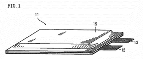
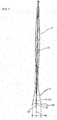
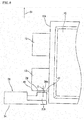
- Film armored battery 11 will be described based on Figs. 1 and 2 .
- Film armored battery 11 is, for example, a lithium ion secondary battery, has an appearance of a shape of a flat rectangle and comprises a pair of tab-shaped terminals 12 and 13 made of an electrically conductive metal foil at one end edge in a longitudinal direction, as shown in Fig. 1 .
- film armored battery 11 contains rectangular power generating element 14 along with an electrolytic solution in outer packaging body 15 made of a laminate film.
- Power generating element 14 comprises a plurality of positive electrode plates 16 and negative electrode plates 17 stacked alternately via separators 18. It includes, for example, three (3) negative electrode plates 17, two (2) positive electrode plates 16, and four (4) separators 18 therebetween. That is, in this embodiment, negative electrodes 17 are located at both faces of power generating element 14. However, there may be a construction in which positive electrodes 16 are located at the outermost layers of power generating element 14. In addition, the dimensions of each part in Fig. 2 are not always accurate and are exaggerated for the purpose of explanation.
- Positive electrode plate 16 comprises positive electrode active material layers 16B and 16C formed on both faces of rectangular positive electrode collector 16A.
- Positive electrode collector 16A is formed of, for example, an electrochemically stable metal foil such as aluminum foil, aluminum alloy foil, copper foil or nickel foil.
- positive electrode active material layers 16B and 16C are formed by, for example, mixing a positive electrode active material such as lithium composite oxide, for example, lithium nickel oxide (LiNiO 2 ), lithium manganese oxide (LiMnO 2 ) or lithium cobalt oxide (LiCoO 2 ), a conductive agent such as carbon black, and a binder, applying the resulting mixture composition to the main surfaces of positive electrode collector 16A and subjecting the applied mixture composition to drying and rolling.
- a positive electrode active material such as lithium composite oxide, for example, lithium nickel oxide (LiNiO 2 ), lithium manganese oxide (LiMnO 2 ) or lithium cobalt oxide (LiCoO 2 )
- a conductive agent such as carbon black
- Negative electrode plate 17 comprises negative electrode active material layers 17B and 17C formed on both faces of rectangular negative electrode collector 17A.
- Negative electrode collector 17 is formed of, for example, an electrochemically stable metal foil such as nickel foil, copper foil, stainless steel foil or iron foil.
- Negative electrode active material layers 17B and 17C are formed by, for example, mixing a negative electrode active material capable of absorbing and desorbing lithium ions of the positive electrode active material, such as amorphous carbon material, hardly-graphitized carbon, easily-graphitized carbon or graphite, with a binder, applying the resulting mixture composition to the main surfaces of negative electrode collector 17A and subjecting the applied mixture composition to drying and rolling.
- Portions of end edges in a longitudinal direction of negative electrode collector 17A extend as extending portions which do not have negative electrode active material layers 17B and 17C, and extremities of the extending portions are joined to negative electrode terminal 13.
- portions of end edges in a longitudinal direction of positive electrode collector 16A extend as extending portions which do not have positive electrode active material layers 16B and 16C, and extremities of the extending portions are joined to positive electrode terminal 12, although not shown in Fig. 2 .
- Separators 18 function to prevent a short circuit between positive and negative electrode plates 16 and 17, and, at the same time, to retain the electrolyte material, and comprise, for example, a microporous film of polyolefin etc. such as polyethylene (PE) or polypropylene (PP) so as to close pores in the porous film by heat generation with the passage of overcurrent and thereby exhibit a current interrupt function.
- separator 18 is not limited to a single-layer film of polyolefin etc. It is also possible to use a three-layer structure in which a polypropylene film is sandwiched between polyethylene films or a laminated structure prepared by laminating a microporous polyolefin film, an organic nonwoven fabric, etc.
- the electrolytic solution there is no particular limitation on the electrolytic solution.
- Outer packaging body 15 which contains power generating element 14 having the above construction, along with an electrolytic solution, is made of a laminate film having a three-layer structure of heat-fusion bonding layer 15A, metal layer 15B and protective layer 15C, as partially shown in enlarged dimension in Fig. 2 .
- Intermediate metal layer 15B is formed of, for example, aluminum foil
- heat-fusion bonding layer 15A which covers an inside surface of metal layer 15B is formed of a synthetic resin capable of heat-fusion bonding such as polypropylene (PP)
- protective layer 15C which covers an outside surface of metal layer 15B is formed of a synthetic resin excellent in durability such as polyethylene terephthalate (PET).
- PET polyethylene terephthalate
- a laminate film having a larger number of layers may be used.
- the synthetic resin layer on the outside surface of metal layer 15B is not necessarily essential. There may be a construction in which a layer of synthetic resin is provided only on the inside surface of metal layer 15B.
- outer packaging body 15 assumes a two-layer structure of one laminate film located on the lower surface side of power generating element 14 in Fig. 2 and the other laminate film located on the upper surface side of power generating element 14, and has a construction in which respective four (4) peripheral sides of the two laminate films are superposed on each other and heat-bonded to each other.
- the illustrated embodiment shows outer packaging body 15 having such a two-layer structure.
- outer packaging body 15 is made of one relatively large laminate film and has a construction in which power generating element 14 is located inside of the laminate film being folded into two, and then the respective three (3) peripheral sides of the two are superposed on each other and heat-bonded to each other.
- the pair of terminals 12 and 13 located on the side of a short side of rectangular film armored battery 11 is drawn through the bonding interface of the laminate film to extend outside of the laminate film when heat bonding the laminate film. Further, although the pair of terminals 12 and 13 is located side by side at the same one end edge in the illustrated embodiment, positive electrode terminal 12 may be located at one end edge and negative electrode terminal 13 may be located at the other end edge.
- Manufacturing procedures of film armored battery 11 are as follows. First, positive electrode plates 16, negative electrode plates 16 and separators 18 are laminated in succession, and terminals 12 and 13 are attached by spot welding etc. to form power generating element 14. Then, power generating element 14 is covered with laminate films as outer packaging body 15 and four peripheral sides (three peripheral sides in the above two-fold) are heat-bonded to each other to leave a relatively small filling port. Then, an electrolytic solution is put into the interior of outer packaging body 15 through the filling port, and then the filling port is heat bonded to bring outer packaging body 15 into an enclosed state. Since film armored battery 11 is thus completed, film armored battery 11 is then charged to a required level and aged in this state for a predetermined length of time. After completion of the aging, film armored battery 11 is charged again for screening such as voltage inspection, and then shipped.
- film armored battery 11 of this type is used as a battery module which contains a plurality of film armored batteries 11 in a flat box type casing.
- outer packaging body 15 may be in a state to be compressed to some extent in a plate stacking direction of power generating element 14 (in a direction perpendicular to the main surface of power generating element 14) by, for example, a portion of the casing or an elastic member which is separate from the casing.
- the screening step a plurality of film armored batteries 11 are stored in compression device 20 (see Fig. 3 ), film armored batteries 11 are compressed as will be described hereinafter, and then whether or not a metallic foreign matter (contamination) exists in the interior of film armored batteries 11 is detected and diagnosed.
- the screening step is performed at an appropriate time after injecting an electrolytic solution and complete enclosing of outer packaging body 15 (sealing of a filling port) in the above manufacturing step.
- the screening step may be provided immediately before shipping as film armored battery 11 or the screening step may be provided immediately after complete enclosing of outer packaging body 15. Further, since a foreign matter may be precipitated in the interior in the aging step, it is also effective to provide the screening step immediately after the aging step.
- a screening step is required to detect (diagnose) whether or not a metallic foreign matter creeps into the interior of film armored battery 11. What should be done to see whether or not the positive electrode active material and the negative electrode active material are short-circuited by a metallic foreign matter is to monitor voltage across a pair of terminals 12 and 13.
- film armored battery 11 is compressed in a plate stacking direction by compression device 20 as will be described hereinafter, and inspection is performed with film armored battery 11 remaining in the compressed state such that a metallic foreign matter can be reliably detected, that is, a metallic foreign matter passes through separator 18.
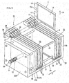
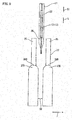
- Figs. 3 to 5 show compression device 20 for film armored battery 11 to which an insertion guide device of the present embodiment is applied.
- the number of movable plates 25 or film armored batteries 11 is not limited to that shown in Fig. 3 , etc.
- Compression device 11 has a lidless box type housing 24 and a plurality of rectangular plate-shaped movable plates (plates) 25.
- Housing 24 has fore wall 24A, aft wall 24B and bottom wall 24C connecting both fore wall 24A and aft wall 24B.
- the plurality of movable plates 25 are arranged in such a state that movable plates 25 can move in predetermined plate stacking direction F.
- Movable plates 25 are of the same shape.
- Movable plates 25 are for applying a surface pressure on the portion of power generating elements 14 of film armored batteries 11 from both sides in plate stacking direction F.
- Each of movable plate 25 is provided with a slide mechanism capable of sliding in plate stacking direction F such that movable plate 25 does not trail along bottom wall 24C of housing 24.
- the slide mechanism has guide holes 26 provided at four (4) corners of movable plate 25 and rod-shaped guide rods 27 which pass loosely through guide holes 26. That is, guide holes 26 are provided at four corners of each movable plate 25 to allow each of stick-shaped guide rods 27 to pass through each of guide holes 26.
- both ends of stick-shaped guide rods 27 are secured to fore wall 24A and aft wall 24B, respectively, such that all movable plates 25 are capable of sliding in plate stacking direction F.
- each of movable plates 25 is provided with bottom wall portion 28 which is bent in a section of L-shape to support the lower end of film armored battery 11.
- Movable plate 25 which is positioned in a leftmost end in Fig. 3 is thick plate 29 for compression which is of slightly larger sectional area and thickness than all other movable plates 25.
- One end of clamping rod 30 externally formed with external threads 31 is secured to thick plate 29.
- Threaded bore 32 internally formed with internal threads having a threaded engagement with external threads 31 at the outer periphery of clamping rod 30 passes through and is defined in fore wall 24A of housing 24.
- clamping rod 30 can move via the thread engaging portion in plate stacking direction F, relative to fore wall 24A of housing 24 to allow thick plate 29 to move in plate stacking direction F. Further, thick plate 29 moves only linearly in plate stacking direction F, without transfer of the rotation of clamping rod 30. Compression force (fastening torque) and compression time by nut runner 23 are managed and controlled by a control portion (not shown).
- each film armored battery 11 is compressed in plate stacking direction F.
- each film armored battery 11 is such that a surface pressure applied on the portion of power generating element 14 thereof from both sides in right and left direction is kept in a state as uniform as possible.
- film armored battery 11 is inserted into space 33 between adjacent movable plates 25 with a posture allowing side edge 15A of outer packaging body 15 from which terminals 12 and 13 are guided out to be along insertion direction S (downward direction in Fig. 3 ) of film armored battery 11 perpendicular to plate stacking direction F.
- the plurality of movable plates 25 are kept in such a state that movable plates 25 are arranged to be spaced equidistantly at regular intervals in plate stacking direction F, with a jig (not shown).
- film armored batteries 11 before insertion are also kept in such a state that film armored batteries 11 are arranged to be spaced equidistantly at regular intervals in plate stacking direction F, with a jig (not shown), that is, each of film armored battery 11 is arranged to be along insertion direction S, above space 33 between movable plates 25.
- film armored battery 11 is inserted into corresponding space 33 by moving film armored battery 11 along insertion direction S to the side of movable plate 25.
- guide member 34 as an insertion guide device for guiding insertion of tab-shaped terminals 12 and 13 when inserting film armored battery is provided.
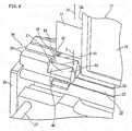
- Guide member 34 is disposed at an upper position of movable plate 25 through which terminals 12 and 13 pass when inserting film armored battery 11, and a plurality of block-shaped guide blocks 36 are secured to attachment plate 35 extending in plate stacking direction F.
- the plurality of guide blocks 36 are arranged to be spaced equidistantly at regular intervals in plate stacking direction in a manner similar to movable plates 25.
- each of guide blocks 36 is provided with guide surface portion 37 tapered toward counter-insertion direction S1 which is a direction opposed to insertion direction S.
- Guide surface portion 37 assumes a triangular cross-section tapered toward apex portion 38 assuming a ridgeline on the side of counter-insertion direction S1, and is located such that each apex portion 38 is positioned at a center of space 33 between movable plates 25 with respect to plate stacking direction F.
- a portion corresponding to base portion 41 close to outer packaging body 15 in terminals 12 and 13, that is, a portion capable of being contacted to base portion 41 of terminals 12 and 13 in a sliding manner is relatively projected toward counter-insertion direction S1, in comparison with a portion corresponding to tip portion 42 far from outer packaging body 15 in terminals 12 and 13, that is, a portion capable of being contacted to tip portion 42 in a sliding manner.
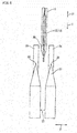
- apex portion 38 takes a tapered shape relatively inclined toward counter-insertion direction S1 (upward direction in Fig. 5 ) as apex portion 38 proceeds from the tip side to the base side of the terminals (that is, as it approaches outer packaging body 15), relative to side edge 39 on the side of insertion direction S of terminals 12 and 13.
- guide surface portion 37 has a construction formed by bending such that, into the side of counter-insertion direction S1 of first inclined surface portion 43 having a relatively small interior angle between two (2) inclined surfaces, second inclined surface portion 44 having a relatively large interior angle between two (2) inclined surfaces merges.
- Guide surface portion 37 assumes such a shape that the formed area of second inclined surface portion 44 gradually becomes larger as guide surface portion 37 proceeds from the base side to the tip side of terminals 12 and 13.
- guide surface portion 37 in apex portion 38 as well as in the portion of the inclined surface is projected toward counter-insertion direction S1 as guide surface portion 37 proceeds from the tip to the base side of the terminals.
- terminal 12 (13) has a larger deformation such as warpage, that is, a larger amount of deformation (amount of warpage) relative to reference plane 45 at a center of a main surface of film armored battery 11, in tip portion 42 than base portion 41 connected to the side of relatively thick outer packaging body 15.
- a portion corresponding to base portion 41 is projected toward the side of counter-insertion direction S1 in comparison with a portion corresponding to tip portion 42.
- guide surface portion 37 is set to be of triangular cross-section, terminals 12 and 13 are reliably guided by an inclined surface of guide surface portion 37 to predetermined space 33 even if terminals 12 and 13 hit the neighborhood of apex portion 38 of guide surface portion 37.
- an inclination angle of apex portion 38 of guide surface portion 37 relative to side edge 39 of the terminal has a slight angle, for example, an angle of 0.2 degrees or more, the effect can be obtained.
- the height difference in apex portion 38 of guide surface portion 37 has a small dimension, for example, a dimension of 0.2 mm or more, the desired effect can be obtained.
- apex portion 38A may be formed in a stepped-shape such that the height of guide surface portion 37A changes in a stepwise fashion, for example, as in another embodiment shown in Fig. 8 . Even in such a case, the portion of guide surface portion 37 on the base side is projected beyond the portion on the tip side so that an effect similar to that in the embodiment can be obtained.
- guide surface portion 37 is set to be of triangular cross-section in the embodiment, the shape of guide surface portion 37 is not limited to such a shape but may be any shape that is tapered toward counter-insertion direction S1, for example, guide surface portion 37B may have the shape of a semicircular cross-section as shown in Fig. 9 .
- guide surface portion 37B has the shape of a semicircular cross-section as just described, however, inclination around the neighborhood of apex portion 38B becomes relatively gentle so that terminals 12 and 13 can enter neighboring spaces other than appropriate space 33 when terminals 12 and 13 hit the neighborhood of apex portion 38B. Therefore, it is most preferable that guide surface portion 37 have the shape of a triangular cross-section like the embodiment.
Landscapes
- Chemical & Material Sciences (AREA)
- Chemical Kinetics & Catalysis (AREA)
- Electrochemistry (AREA)
- General Chemical & Material Sciences (AREA)
- Engineering & Computer Science (AREA)
- Manufacturing & Machinery (AREA)
- Battery Mounting, Suspending (AREA)
- Sealing Battery Cases Or Jackets (AREA)
- Secondary Cells (AREA)
- Materials Engineering (AREA)
Claims (4)
- Einsatzführungsvorrichtung für eine filmbeschichtete Batterie (11), die eine flache filmbeschichtete Batterie (11) mit einer streifenförmigen Anschlussklemme (12, 13), welche von einem Seitenrand (15A) eines rechtwinkligen äußeren Verpackungskörpers (15) herausgeführt wird, in einen Raum (33) zwischen einer Vielzahl von Platten (25), die in einer vorgegebenen Plattenstapelrichtung (F) angeordnet sind, so dass sie einander in vorgegebenen Intervallen beabstanden, in einer vorgegebenen Einsatzrichtung (S) lotrecht zu der Plattenstapelrichtung (F) einsetzt,
wobei die filmbeschichtete Batterie (11) mit einer solchen Ausrichtung eingesetzt wird, dass der Seitenrand (15A) des äußeren Verpackungskörpers (15) von dem die Anschlussklemme (12, 13) herausgeführt wird, entlang der Einsatzrichtung (S) verlaufen kann, und
wobei ein Führungselement (34) zum Führen der Anschlussklemme (12, 13) in den Raum (33) zwischen den Platten (25) während des Einsetzens der filmbeschichteten Batterie (11) vorgesehen ist,
wobei in dem Führungselement (34) ein Abschnitt entsprechend einem Basisabschnitt (41) in der Nähe des äußeren Verpackungskörpers (15) in der Anschlussklemme (12, 13) relativ in Richtung einer der Einsatzrichtung entgegengesetzten Richtung (S1) vorsteht, im Vergleich zu einem Abschnitt entsprechend einem Spitzenabschnitt (42), der von dem äußeren Verpackungskörper (15) in der Anschlussklemme (12, 13) weit entfernt ist. - Einsatzführungsvorrichtung für eine filmbeschichtete Batterie (11) nach Anspruch 1, wobei das Führungselement (34) einen Führungsflächenabschnitt (37) aufweist, der in Richtung einer der Einsatzrichtung entgegengesetzten Richtung (S1) verjüngt ist, bei der es sich um eine Richtung gegen die Einsatzrichtung (S) handelt.
- Einsatzführungsvorrichtung für eine filmbeschichtete Batterie (11) nach Anspruch 2, wobei ein Scheitelabschnitt (38) des Führungsflächenabschnitts (37) solcher Art geneigt ist, dass der Abschnitt entsprechend dem Basisabschnitt (41) der Anschlussklemme (12, 13) in Richtung der der Einsatzrichtung entgegengesetzten Richtung (S1) relativ zu einem Seitenrand (39) auf der Seite der Einführung der Anschlussklemme (12, 13) vorsteht.
- Einsatzführungsvorrichtung für eine filmbeschichtete Batterie nach Anspruch 2 oder 3, wobei der Führungsflächenabschnitt (37) eine Form mit einem dreieckigen Querschnitt aufweist, die sich in Richtung des Scheitelabschnitts (38) verjüngt.
Applications Claiming Priority (2)
| Application Number | Priority Date | Filing Date | Title |
|---|---|---|---|
| JP2013168417 | 2013-08-14 | ||
| PCT/JP2014/066231 WO2015022811A1 (ja) | 2013-08-14 | 2014-06-19 | フィルム外装電池の挿入案内装置 |
Publications (3)
| Publication Number | Publication Date |
|---|---|
| EP3035408A1 EP3035408A1 (de) | 2016-06-22 |
| EP3035408A4 EP3035408A4 (de) | 2016-08-31 |
| EP3035408B1 true EP3035408B1 (de) | 2017-08-09 |
Family
ID=52468201
Family Applications (1)
| Application Number | Title | Priority Date | Filing Date |
|---|---|---|---|
| EP14836505.9A Active EP3035408B1 (de) | 2013-08-14 | 2014-06-19 | Einsatzführungsvorrichtung für eine filmbeschichtete batterie |
Country Status (6)
| Country | Link |
|---|---|
| US (1) | US9905815B2 (de) |
| EP (1) | EP3035408B1 (de) |
| JP (1) | JP6088054B2 (de) |
| KR (1) | KR101896162B1 (de) |
| CN (1) | CN105594013B (de) |
| WO (1) | WO2015022811A1 (de) |
Families Citing this family (14)
| Publication number | Priority date | Publication date | Assignee | Title |
|---|---|---|---|---|
| JP6540368B2 (ja) * | 2015-08-21 | 2019-07-10 | 日産自動車株式会社 | 電池セル収納装置 |
| WO2017176462A1 (en) | 2016-04-03 | 2017-10-12 | Brammo, Inc. | Battery pack and method of manufacture |
| JP6885798B2 (ja) * | 2016-07-20 | 2021-06-16 | 株式会社エンビジョンAescジャパン | 電池取出装置 |
| JP6800419B2 (ja) * | 2017-02-03 | 2020-12-16 | 株式会社エンビジョンAescジャパン | チャック装置 |
| AT519967B1 (de) * | 2017-06-08 | 2018-12-15 | Avl List Gmbh | Einbauverfahren für batteriezellen in ein gehäuse sowie einbauvorrichtung hierfür |
| KR102015901B1 (ko) * | 2019-04-25 | 2019-08-28 | 백영진 | 2차전지셀 케이스 삽입 장치 |
| CN110482176B (zh) * | 2019-08-09 | 2024-12-20 | 苏州富强科技有限公司 | 一种扶正导向机构 |
| CN110436172B (zh) * | 2019-08-09 | 2024-08-02 | 苏州富强科技有限公司 | 一种顶升式物料取出装置 |
| KR102832709B1 (ko) | 2019-08-30 | 2025-07-09 | 주식회사 엘지에너지솔루션 | 이차전지 충방전 장치 |
| DE102021115451A1 (de) * | 2021-06-15 | 2022-12-15 | Bayerische Motoren Werke Aktiengesellschaft | Vorrichtung zum Komprimieren zumindest eines Abschnitts einer Energiespeicherzelle sowie System und Verfahren zur elektrischen Sicherheitsprüfung |
| CN113540704B (zh) * | 2021-07-14 | 2023-06-20 | 东莞新能安科技有限公司 | 电池模组及用电设备 |
| KR20230082138A (ko) * | 2021-12-01 | 2023-06-08 | 주식회사 엘지에너지솔루션 | 탭 가이드 및 탭 가이드를 포함하는 탭 가이드 장치 |
| CN115570049B (zh) * | 2022-10-25 | 2023-11-28 | 宿迁市华力新材料科技有限公司 | 一种腐蚀箔波浪边的矫正装置 |
| KR102865025B1 (ko) * | 2022-11-24 | 2025-09-29 | 주식회사 성우하이텍 | 배터리 셀 조립용 센싱 블록 및 이를 포함하는 배터리 모듈 |
Family Cites Families (12)
| Publication number | Priority date | Publication date | Assignee | Title |
|---|---|---|---|---|
| US5558956A (en) * | 1995-08-30 | 1996-09-24 | Gujer; Rudolf | System for isolating batteries during testing |
| JP3952345B2 (ja) | 1999-02-04 | 2007-08-01 | 日立マクセル株式会社 | 密閉型の電池 |
| JP2001057197A (ja) * | 1999-08-18 | 2001-02-27 | Toshiba Battery Co Ltd | 薄型電池用搬送治具 |
| JP2002231320A (ja) * | 2001-01-31 | 2002-08-16 | Sony Corp | 電池用トレイ |
| JP5582815B2 (ja) * | 2010-02-18 | 2014-09-03 | 日本航空電子工業株式会社 | 電池間接続装置 |
| JP5533317B2 (ja) | 2010-06-17 | 2014-06-25 | 日産自動車株式会社 | ラミネート型電池の加圧装置 |
| JP5499928B2 (ja) * | 2010-06-17 | 2014-05-21 | 日産自動車株式会社 | ラミネート型電池の加圧装置 |
| JP5831923B2 (ja) * | 2011-03-31 | 2015-12-09 | Necエナジーデバイス株式会社 | 電池パック |
| JP5765769B2 (ja) * | 2011-03-31 | 2015-08-19 | Necエナジーデバイス株式会社 | 電池パック |
| US9356278B2 (en) * | 2011-03-31 | 2016-05-31 | Nec Energy Devices, Ltd. | Battery pack |
| JP2013143309A (ja) * | 2012-01-12 | 2013-07-22 | Hitachi Maxell Ltd | トレー、主トレー、およびトレーセット |
| JP5946648B2 (ja) * | 2012-02-13 | 2016-07-06 | 日産自動車株式会社 | 電池セル搬送システム |
-
2014
- 2014-06-19 KR KR1020167003088A patent/KR101896162B1/ko active Active
- 2014-06-19 US US14/909,649 patent/US9905815B2/en active Active
- 2014-06-19 EP EP14836505.9A patent/EP3035408B1/de active Active
- 2014-06-19 WO PCT/JP2014/066231 patent/WO2015022811A1/ja not_active Ceased
- 2014-06-19 CN CN201480044229.3A patent/CN105594013B/zh active Active
- 2014-06-19 JP JP2015531740A patent/JP6088054B2/ja active Active
Non-Patent Citations (1)
| Title |
|---|
| None * |
Also Published As
| Publication number | Publication date |
|---|---|
| WO2015022811A1 (ja) | 2015-02-19 |
| JP6088054B2 (ja) | 2017-03-01 |
| EP3035408A4 (de) | 2016-08-31 |
| CN105594013B (zh) | 2018-01-09 |
| EP3035408A1 (de) | 2016-06-22 |
| CN105594013A (zh) | 2016-05-18 |
| JPWO2015022811A1 (ja) | 2017-03-02 |
| KR20160027193A (ko) | 2016-03-09 |
| US9905815B2 (en) | 2018-02-27 |
| KR101896162B1 (ko) | 2018-09-07 |
| US20160172636A1 (en) | 2016-06-16 |
Similar Documents
| Publication | Publication Date | Title |
|---|---|---|
| EP3035408B1 (de) | Einsatzführungsvorrichtung für eine filmbeschichtete batterie | |
| EP2254176B1 (de) | Wiederaufladbare Batterie | |
| KR101379957B1 (ko) | 단차를 갖는 전극 조립체 및 이를 포함하는 전지셀, 전지팩 및 디바이스 | |
| US20160260978A1 (en) | Electrode and Battery Including Electrode | |
| JP6531486B2 (ja) | 電池 | |
| KR20130097881A (ko) | 이차전지의 제조방법 및 이를 이용하여 생산되는 이차전지 | |
| DE112014001987T5 (de) | Akkumulatorvorrichtung | |
| WO2017169130A1 (ja) | 積層型リチウムイオン電池 | |
| KR20160111855A (ko) | 축전 소자 | |
| JP2015037047A (ja) | フィルム外装電池の加圧方法 | |
| KR101580086B1 (ko) | 복합 구조로 형성된 전극조립체 | |
| JP6693453B2 (ja) | 蓄電装置及び蓄電装置の製造方法 | |
| KR101245288B1 (ko) | 셀 어셈블리와 파우치형 케이스의 밀착성을 향상시킨 이차전지 및 그 제조방법 | |
| KR20220002540A (ko) | 셀 배터리 | |
| JP2019061881A (ja) | 蓄電素子 | |
| JP2009117255A (ja) | 二次電池、組電池および車両 | |
| JP7133137B2 (ja) | 蓄電素子 | |
| JP6781074B2 (ja) | 二次電池 | |
| US10930979B2 (en) | Energy storage device and method of manufacturing energy storage device | |
| KR102317274B1 (ko) | 배터리 모듈 및 이를 포함하는 배터리 팩 | |
| KR102108208B1 (ko) | 원형 전극을 포함하는 원통형 이차전지 | |
| JP7237513B2 (ja) | 電気化学素子 | |
| JP5216292B2 (ja) | 蓄電素子 | |
| KR102267586B1 (ko) | 배터리 모듈 | |
| KR20160054268A (ko) | 이차전지셀 및 이를 포함하는 배터리 모듈 |
Legal Events
| Date | Code | Title | Description |
|---|---|---|---|
| PUAI | Public reference made under article 153(3) epc to a published international application that has entered the european phase |
Free format text: ORIGINAL CODE: 0009012 |
|
| 17P | Request for examination filed |
Effective date: 20160314 |
|
| AK | Designated contracting states |
Kind code of ref document: A1 Designated state(s): AL AT BE BG CH CY CZ DE DK EE ES FI FR GB GR HR HU IE IS IT LI LT LU LV MC MK MT NL NO PL PT RO RS SE SI SK SM TR |
|
| AX | Request for extension of the european patent |
Extension state: BA ME |
|
| A4 | Supplementary search report drawn up and despatched |
Effective date: 20160803 |
|
| RIC1 | Information provided on ipc code assigned before grant |
Ipc: H01M 10/04 20060101ALI20160728BHEP Ipc: H01M 2/10 20060101AFI20160728BHEP Ipc: H01M 10/48 20060101ALI20160728BHEP Ipc: H01M 2/02 20060101ALI20160728BHEP |
|
| DAX | Request for extension of the european patent (deleted) | ||
| GRAP | Despatch of communication of intention to grant a patent |
Free format text: ORIGINAL CODE: EPIDOSNIGR1 |
|
| RIC1 | Information provided on ipc code assigned before grant |
Ipc: H01M 2/10 20060101AFI20170316BHEP Ipc: H01M 10/04 20060101ALN20170316BHEP Ipc: H01M 10/48 20060101ALI20170316BHEP Ipc: H01M 2/02 20060101ALI20170316BHEP Ipc: H01M 10/052 20100101ALN20170316BHEP |
|
| INTG | Intention to grant announced |
Effective date: 20170331 |
|
| GRAS | Grant fee paid |
Free format text: ORIGINAL CODE: EPIDOSNIGR3 |
|
| GRAA | (expected) grant |
Free format text: ORIGINAL CODE: 0009210 |
|
| AK | Designated contracting states |
Kind code of ref document: B1 Designated state(s): AL AT BE BG CH CY CZ DE DK EE ES FI FR GB GR HR HU IE IS IT LI LT LU LV MC MK MT NL NO PL PT RO RS SE SI SK SM TR |
|
| REG | Reference to a national code |
Ref country code: GB Ref legal event code: FG4D |
|
| REG | Reference to a national code |
Ref country code: CH Ref legal event code: EP Ref country code: AT Ref legal event code: REF Ref document number: 917719 Country of ref document: AT Kind code of ref document: T Effective date: 20170815 |
|
| REG | Reference to a national code |
Ref country code: IE Ref legal event code: FG4D |
|
| REG | Reference to a national code |
Ref country code: DE Ref legal event code: R096 Ref document number: 602014013040 Country of ref document: DE |
|
| REG | Reference to a national code |
Ref country code: NL Ref legal event code: MP Effective date: 20170809 |
|
| REG | Reference to a national code |
Ref country code: LT Ref legal event code: MG4D |
|
| REG | Reference to a national code |
Ref country code: AT Ref legal event code: MK05 Ref document number: 917719 Country of ref document: AT Kind code of ref document: T Effective date: 20170809 |
|
| PG25 | Lapsed in a contracting state [announced via postgrant information from national office to epo] |
Ref country code: AT Free format text: LAPSE BECAUSE OF FAILURE TO SUBMIT A TRANSLATION OF THE DESCRIPTION OR TO PAY THE FEE WITHIN THE PRESCRIBED TIME-LIMIT Effective date: 20170809 Ref country code: NL Free format text: LAPSE BECAUSE OF FAILURE TO SUBMIT A TRANSLATION OF THE DESCRIPTION OR TO PAY THE FEE WITHIN THE PRESCRIBED TIME-LIMIT Effective date: 20170809 Ref country code: NO Free format text: LAPSE BECAUSE OF FAILURE TO SUBMIT A TRANSLATION OF THE DESCRIPTION OR TO PAY THE FEE WITHIN THE PRESCRIBED TIME-LIMIT Effective date: 20171109 Ref country code: FI Free format text: LAPSE BECAUSE OF FAILURE TO SUBMIT A TRANSLATION OF THE DESCRIPTION OR TO PAY THE FEE WITHIN THE PRESCRIBED TIME-LIMIT Effective date: 20170809 Ref country code: HR Free format text: LAPSE BECAUSE OF FAILURE TO SUBMIT A TRANSLATION OF THE DESCRIPTION OR TO PAY THE FEE WITHIN THE PRESCRIBED TIME-LIMIT Effective date: 20170809 Ref country code: SE Free format text: LAPSE BECAUSE OF FAILURE TO SUBMIT A TRANSLATION OF THE DESCRIPTION OR TO PAY THE FEE WITHIN THE PRESCRIBED TIME-LIMIT Effective date: 20170809 Ref country code: LT Free format text: LAPSE BECAUSE OF FAILURE TO SUBMIT A TRANSLATION OF THE DESCRIPTION OR TO PAY THE FEE WITHIN THE PRESCRIBED TIME-LIMIT Effective date: 20170809 |
|
| PG25 | Lapsed in a contracting state [announced via postgrant information from national office to epo] |
Ref country code: ES Free format text: LAPSE BECAUSE OF FAILURE TO SUBMIT A TRANSLATION OF THE DESCRIPTION OR TO PAY THE FEE WITHIN THE PRESCRIBED TIME-LIMIT Effective date: 20170809 Ref country code: GR Free format text: LAPSE BECAUSE OF FAILURE TO SUBMIT A TRANSLATION OF THE DESCRIPTION OR TO PAY THE FEE WITHIN THE PRESCRIBED TIME-LIMIT Effective date: 20171110 Ref country code: BG Free format text: LAPSE BECAUSE OF FAILURE TO SUBMIT A TRANSLATION OF THE DESCRIPTION OR TO PAY THE FEE WITHIN THE PRESCRIBED TIME-LIMIT Effective date: 20171109 Ref country code: PL Free format text: LAPSE BECAUSE OF FAILURE TO SUBMIT A TRANSLATION OF THE DESCRIPTION OR TO PAY THE FEE WITHIN THE PRESCRIBED TIME-LIMIT Effective date: 20170809 Ref country code: RS Free format text: LAPSE BECAUSE OF FAILURE TO SUBMIT A TRANSLATION OF THE DESCRIPTION OR TO PAY THE FEE WITHIN THE PRESCRIBED TIME-LIMIT Effective date: 20170809 Ref country code: IS Free format text: LAPSE BECAUSE OF FAILURE TO SUBMIT A TRANSLATION OF THE DESCRIPTION OR TO PAY THE FEE WITHIN THE PRESCRIBED TIME-LIMIT Effective date: 20171209 Ref country code: LV Free format text: LAPSE BECAUSE OF FAILURE TO SUBMIT A TRANSLATION OF THE DESCRIPTION OR TO PAY THE FEE WITHIN THE PRESCRIBED TIME-LIMIT Effective date: 20170809 |
|
| PG25 | Lapsed in a contracting state [announced via postgrant information from national office to epo] |
Ref country code: DK Free format text: LAPSE BECAUSE OF FAILURE TO SUBMIT A TRANSLATION OF THE DESCRIPTION OR TO PAY THE FEE WITHIN THE PRESCRIBED TIME-LIMIT Effective date: 20170809 Ref country code: CZ Free format text: LAPSE BECAUSE OF FAILURE TO SUBMIT A TRANSLATION OF THE DESCRIPTION OR TO PAY THE FEE WITHIN THE PRESCRIBED TIME-LIMIT Effective date: 20170809 Ref country code: RO Free format text: LAPSE BECAUSE OF FAILURE TO SUBMIT A TRANSLATION OF THE DESCRIPTION OR TO PAY THE FEE WITHIN THE PRESCRIBED TIME-LIMIT Effective date: 20170809 |
|
| REG | Reference to a national code |
Ref country code: FR Ref legal event code: PLFP Year of fee payment: 5 Ref country code: DE Ref legal event code: R097 Ref document number: 602014013040 Country of ref document: DE |
|
| PG25 | Lapsed in a contracting state [announced via postgrant information from national office to epo] |
Ref country code: SM Free format text: LAPSE BECAUSE OF FAILURE TO SUBMIT A TRANSLATION OF THE DESCRIPTION OR TO PAY THE FEE WITHIN THE PRESCRIBED TIME-LIMIT Effective date: 20170809 Ref country code: EE Free format text: LAPSE BECAUSE OF FAILURE TO SUBMIT A TRANSLATION OF THE DESCRIPTION OR TO PAY THE FEE WITHIN THE PRESCRIBED TIME-LIMIT Effective date: 20170809 Ref country code: IT Free format text: LAPSE BECAUSE OF FAILURE TO SUBMIT A TRANSLATION OF THE DESCRIPTION OR TO PAY THE FEE WITHIN THE PRESCRIBED TIME-LIMIT Effective date: 20170809 Ref country code: SK Free format text: LAPSE BECAUSE OF FAILURE TO SUBMIT A TRANSLATION OF THE DESCRIPTION OR TO PAY THE FEE WITHIN THE PRESCRIBED TIME-LIMIT Effective date: 20170809 |
|
| PLBE | No opposition filed within time limit |
Free format text: ORIGINAL CODE: 0009261 |
|
| STAA | Information on the status of an ep patent application or granted ep patent |
Free format text: STATUS: NO OPPOSITION FILED WITHIN TIME LIMIT |
|
| 26N | No opposition filed |
Effective date: 20180511 |
|
| PG25 | Lapsed in a contracting state [announced via postgrant information from national office to epo] |
Ref country code: SI Free format text: LAPSE BECAUSE OF FAILURE TO SUBMIT A TRANSLATION OF THE DESCRIPTION OR TO PAY THE FEE WITHIN THE PRESCRIBED TIME-LIMIT Effective date: 20170809 |
|
| REG | Reference to a national code |
Ref country code: CH Ref legal event code: PL |
|
| REG | Reference to a national code |
Ref country code: BE Ref legal event code: MM Effective date: 20180630 |
|
| REG | Reference to a national code |
Ref country code: IE Ref legal event code: MM4A |
|
| PG25 | Lapsed in a contracting state [announced via postgrant information from national office to epo] |
Ref country code: LU Free format text: LAPSE BECAUSE OF NON-PAYMENT OF DUE FEES Effective date: 20180619 Ref country code: MC Free format text: LAPSE BECAUSE OF FAILURE TO SUBMIT A TRANSLATION OF THE DESCRIPTION OR TO PAY THE FEE WITHIN THE PRESCRIBED TIME-LIMIT Effective date: 20170809 |
|
| PG25 | Lapsed in a contracting state [announced via postgrant information from national office to epo] |
Ref country code: IE Free format text: LAPSE BECAUSE OF NON-PAYMENT OF DUE FEES Effective date: 20180619 Ref country code: CH Free format text: LAPSE BECAUSE OF NON-PAYMENT OF DUE FEES Effective date: 20180630 Ref country code: LI Free format text: LAPSE BECAUSE OF NON-PAYMENT OF DUE FEES Effective date: 20180630 |
|
| PG25 | Lapsed in a contracting state [announced via postgrant information from national office to epo] |
Ref country code: BE Free format text: LAPSE BECAUSE OF NON-PAYMENT OF DUE FEES Effective date: 20180630 |
|
| REG | Reference to a national code |
Ref country code: DE Ref legal event code: R082 Ref document number: 602014013040 Country of ref document: DE Representative=s name: GRUENECKER PATENT- UND RECHTSANWAELTE PARTG MB, DE Ref country code: DE Ref legal event code: R081 Ref document number: 602014013040 Country of ref document: DE Owner name: ENVISION AESC JAPAN LTD., ZAMA-SHI, JP Free format text: FORMER OWNERS: AUTOMOTIVE ENERGY SUPPLY CORP., ZAMA-SHI, KANAGAWA, JP; NISSAN MOTOR CO., LTD., YOKOHAMA-SHI, KANAGAWA-KEN, JP |
|
| REG | Reference to a national code |
Ref country code: GB Ref legal event code: 732E Free format text: REGISTERED BETWEEN 20190926 AND 20191002 |
|
| PG25 | Lapsed in a contracting state [announced via postgrant information from national office to epo] |
Ref country code: MT Free format text: LAPSE BECAUSE OF NON-PAYMENT OF DUE FEES Effective date: 20180619 |
|
| PG25 | Lapsed in a contracting state [announced via postgrant information from national office to epo] |
Ref country code: TR Free format text: LAPSE BECAUSE OF FAILURE TO SUBMIT A TRANSLATION OF THE DESCRIPTION OR TO PAY THE FEE WITHIN THE PRESCRIBED TIME-LIMIT Effective date: 20170809 |
|
| PG25 | Lapsed in a contracting state [announced via postgrant information from national office to epo] |
Ref country code: PT Free format text: LAPSE BECAUSE OF FAILURE TO SUBMIT A TRANSLATION OF THE DESCRIPTION OR TO PAY THE FEE WITHIN THE PRESCRIBED TIME-LIMIT Effective date: 20170809 |
|
| PG25 | Lapsed in a contracting state [announced via postgrant information from national office to epo] |
Ref country code: HU Free format text: LAPSE BECAUSE OF FAILURE TO SUBMIT A TRANSLATION OF THE DESCRIPTION OR TO PAY THE FEE WITHIN THE PRESCRIBED TIME-LIMIT; INVALID AB INITIO Effective date: 20140619 Ref country code: MK Free format text: LAPSE BECAUSE OF NON-PAYMENT OF DUE FEES Effective date: 20170809 Ref country code: CY Free format text: LAPSE BECAUSE OF FAILURE TO SUBMIT A TRANSLATION OF THE DESCRIPTION OR TO PAY THE FEE WITHIN THE PRESCRIBED TIME-LIMIT Effective date: 20170809 |
|
| PG25 | Lapsed in a contracting state [announced via postgrant information from national office to epo] |
Ref country code: AL Free format text: LAPSE BECAUSE OF FAILURE TO SUBMIT A TRANSLATION OF THE DESCRIPTION OR TO PAY THE FEE WITHIN THE PRESCRIBED TIME-LIMIT Effective date: 20170809 |
|
| REG | Reference to a national code |
Ref country code: DE Ref legal event code: R079 Ref document number: 602014013040 Country of ref document: DE Free format text: PREVIOUS MAIN CLASS: H01M0002100000 Ipc: H01M0050200000 |
|
| P01 | Opt-out of the competence of the unified patent court (upc) registered |
Effective date: 20230330 |
|
| PGFP | Annual fee paid to national office [announced via postgrant information from national office to epo] |
Ref country code: DE Payment date: 20250423 Year of fee payment: 12 |
|
| PGFP | Annual fee paid to national office [announced via postgrant information from national office to epo] |
Ref country code: GB Payment date: 20250501 Year of fee payment: 12 |
|
| PGFP | Annual fee paid to national office [announced via postgrant information from national office to epo] |
Ref country code: FR Payment date: 20250422 Year of fee payment: 12 |