EP3035490A1 - Testeur de dispositif mobile pour mesure de puissance inductive précise et unité d'étalonnage correspondant - Google Patents
Testeur de dispositif mobile pour mesure de puissance inductive précise et unité d'étalonnage correspondant Download PDFInfo
- Publication number
- EP3035490A1 EP3035490A1 EP15201227.4A EP15201227A EP3035490A1 EP 3035490 A1 EP3035490 A1 EP 3035490A1 EP 15201227 A EP15201227 A EP 15201227A EP 3035490 A1 EP3035490 A1 EP 3035490A1
- Authority
- EP
- European Patent Office
- Prior art keywords
- mdt
- transmitter coil
- primary transmitter
- voltage
- inductive power
- Prior art date
- Legal status (The legal status is an assumption and is not a legal conclusion. Google has not performed a legal analysis and makes no representation as to the accuracy of the status listed.)
- Granted
Links
Images

Classifications
-
- H—ELECTRICITY
- H04—ELECTRIC COMMUNICATION TECHNIQUE
- H04B—TRANSMISSION
- H04B5/00—Near-field transmission systems, e.g. inductive or capacitive transmission systems
- H04B5/70—Near-field transmission systems, e.g. inductive or capacitive transmission systems specially adapted for specific purposes
- H04B5/79—Near-field transmission systems, e.g. inductive or capacitive transmission systems specially adapted for specific purposes for data transfer in combination with power transfer
-
- G—PHYSICS
- G01—MEASURING; TESTING
- G01R—MEASURING ELECTRIC VARIABLES; MEASURING MAGNETIC VARIABLES
- G01R31/00—Arrangements for testing electric properties; Arrangements for locating electric faults; Arrangements for electrical testing characterised by what is being tested not provided for elsewhere
-
- H—ELECTRICITY
- H02—GENERATION; CONVERSION OR DISTRIBUTION OF ELECTRIC POWER
- H02J—ELECTRIC POWER NETWORKS; CIRCUIT ARRANGEMENTS OR SYSTEMS FOR SUPPLYING OR DISTRIBUTING ELECTRIC POWER; SYSTEMS FOR STORING ELECTRIC ENERGY
- H02J50/00—Circuit arrangements or systems for wireless supply or distribution of electric power
- H02J50/10—Circuit arrangements or systems for wireless supply or distribution of electric power using inductive coupling
-
- G—PHYSICS
- G01—MEASURING; TESTING
- G01R—MEASURING ELECTRIC VARIABLES; MEASURING MAGNETIC VARIABLES
- G01R21/00—Arrangements for measuring electric power or power factor
- G01R21/133—Arrangements for measuring electric power or power factor by using digital technique
-
- H—ELECTRICITY
- H02—GENERATION; CONVERSION OR DISTRIBUTION OF ELECTRIC POWER
- H02J—ELECTRIC POWER NETWORKS; CIRCUIT ARRANGEMENTS OR SYSTEMS FOR SUPPLYING OR DISTRIBUTING ELECTRIC POWER; SYSTEMS FOR STORING ELECTRIC ENERGY
- H02J50/00—Circuit arrangements or systems for wireless supply or distribution of electric power
- H02J50/10—Circuit arrangements or systems for wireless supply or distribution of electric power using inductive coupling
- H02J50/12—Circuit arrangements or systems for wireless supply or distribution of electric power using inductive coupling of the resonant type
-
- H—ELECTRICITY
- H04—ELECTRIC COMMUNICATION TECHNIQUE
- H04B—TRANSMISSION
- H04B5/00—Near-field transmission systems, e.g. inductive or capacitive transmission systems
- H04B5/20—Near-field transmission systems, e.g. inductive or capacitive transmission systems characterised by the transmission technique; characterised by the transmission medium
- H04B5/24—Inductive coupling
- H04B5/26—Inductive coupling using coils
-
- G—PHYSICS
- G01—MEASURING; TESTING
- G01R—MEASURING ELECTRIC VARIABLES; MEASURING MAGNETIC VARIABLES
- G01R31/00—Arrangements for testing electric properties; Arrangements for locating electric faults; Arrangements for electrical testing characterised by what is being tested not provided for elsewhere
- G01R31/28—Testing of electronic circuits, e.g. by signal tracer
- G01R31/2832—Specific tests of electronic circuits not provided for elsewhere
- G01R31/2836—Fault-finding or characterising
- G01R31/2839—Fault-finding or characterising using signal generators, power supplies or circuit analysers
-
- G—PHYSICS
- G01—MEASURING; TESTING
- G01R—MEASURING ELECTRIC VARIABLES; MEASURING MAGNETIC VARIABLES
- G01R31/00—Arrangements for testing electric properties; Arrangements for locating electric faults; Arrangements for electrical testing characterised by what is being tested not provided for elsewhere
- G01R31/40—Testing power supplies
Definitions
- the present invention relates to a test unit for testing the inductive charging capabilities of a mobile device. More particularly, the present invention relates to a test unit with a precisely calibrated power output for testing the inductive charging capabilities of a mobile device.
- test unit In order to assess the inductive power charging capabilities of a mobile device, such as a mobile phone or smart phone, a test unit is used.
- a problem of conventional test unit is that the accuracy of the inductive power transmitted by such a test unit in use, is poor.
- a test unit for testing inductive power charging of a mobile device, with a precisely calibrated power output.
- the test unit comprises an electrical circuit being powered by a DC power source, the circuit being capable of generating electrical power at each of a number of frequencies f , the electrical circuit comprising a primary transmitter coil for inductively transmitting power to a secondary receiver coil of the mobile device in use, and a capacitor connected in series with the primary transmitter in order to get a resonance circuit with resonance at a certain frequency.
- the test unit further comprises a control unit configured to operate in a calibration mode and a testing mode. In the power calibration mode the control unit is configured to:
- a calibrator unit for calibrating a test unit.
- the calibrator comprises an electrical circuit having a secondary receiver coil for receiving electrical power of a certain frequency from a primary transmitter coil of the test unit in use, and a resistor connected in series with the secondary receiver coil and having a well defined resistance R CAL .
- the calibrator unit further comprises a calibrator control unit configured to:
- a method for testing inductive power charging of a mobile device, using a test unit having a precisely calibrated power output and operating in a calibration mode comprises:
- An advantage according to some embodiments is that a very precise power output measurement is achieved by the test unit. This allows for a very accurate quality assessment of the inductive power charging capability of a mobile device when connected to the test unit.
- a general idea of the present invention is to provide a test unit for testing inductive power charging of a mobile device, wherein the test unit has a precisely calibrated power output.
- the test unit calculates a number of constants required for determining the precisely calibrated output.
- the test unit is capable of calculating its inductive power output, regardless of the type of secondary receiver coil of any device being inductively connected thereto.
- the test unit calculates the power output when a mobile device is inductively connected thereto, and compares this calculated output to the measurement values of the received inductive power sent by the mobile device to determine a quality assessment of the inductive power measuring capability of the mobile device.
- test unit may throughout the present specification also be referred to as a mobile device test (MDT) unit being used for testing the inductive power charging capability of a mobile device.
- MDT mobile device test
- mobile device may throughout the present specification be a mobile terminal, such as a mobile phone, or smartphone, being capable of inductive charging.
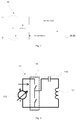
- a test unit 10 for testing inductive power charging of a mobile device 30 comprises an electrical circuit 11 being powered by a DC power source 113.
- the circuit is capable of generating electrical power at each of a number of frequencies f .
- the electrical circuit 11 comprises a primary transmitter coil 111 for inductively transmitting power to a secondary receiver coil of the mobile device in use.
- the electrical circuit 11 further comprises a capacitor 112 connected in series with the primary transmitter coil in order to get a resonance circuit with resonance at a certain frequency.
- the test unit 10 further comprises a control unit 12 configured to operate in a calibration mode and a testing mode.
- the control unit 12 may be a conventional processor with a memory. The control unit is able to store the result of any derived parameter, calculation, and/or processing made into its memory.
- control unit 12 In the calibration mode the control unit 12 is configured to receive a measurement of a voltage U supplied over the primary transmitter coil 111. The voltage is measured using a high resolution ADC (not shown) over the primary transmitter coil 111. It may be observed from Fig. 2 , that a switch configuration 114 creates an AC signal seen on the right of the switch configuration 114 of Fig. 2 , from a DC signal seen on the left side originating from the DC power source.
- the control unit 12 is further configured to receive measurement of a current I flowing through the primary transmitter coil. The current measurement may be measured using a current sense transformer connected to a high resolution ADC (not shown).
- the control unit 12 In order for the control unit 12 to precisely calculate the inductive power transmitted from the primary transmitter coil 111, it is configured to execute a number of parameters affecting the power output.
- a time compensation parameter ⁇ t(f) is derived for each power frequency f of the power supplied by the power source.
- the time compensation parameter ⁇ t(f) compensates for phase shifts in the signal paths in the electrical circuit 11 between the measured voltage U and the measured current I .
- the time compensation parameter is derived by time or phase shifting the measured current I in relation to the measured voltage U, such that the integrated product of I ⁇ t( ⁇ ) and U over a period is zero when no secondary receiver coil is inductively coupled to the primary transmitter coil.
- the control unit is configured to store each time compensation parameter in its memory.
- the time compensation parameter is required for a mathematical formula used to calculate the inductive power transmitted from the primary transmitter coil.
- the time compensation parameter ⁇ t(f) defines the relation between the measured current I and measured voltage U, such that the integrated product, i.e. the calculated power, of I and U over a period is zero when no secondary receiver coil is inductively coupled to the primary transmitter coil.
- the current is time or phase shifted by the time compensation parameter or the measured voltage could be time or phase shifted.
- the measured current I is time compensated by the time compensation parameter, although the scope of the present specification also encompasses the embodiment where the measured voltage could be time compensated.
- the control unit 12 can determine a voltage amplification constant K U-MDT (f).
- the voltage amplification constant K U-MDT (f) is measured in a state where no secondary receiver coil is inductively coupled to the primary transmitter coil.
- the voltage amplification constant attains a single value for each power frequency.
- a mean constant relevant for a number of power frequencies may also be determined for simplicity.
- the external voltmeter measures the voltage directly over the primary transmitter coil, thereby giving a reference voltage.
- the voltage amplification constant K U-MDT (f) is derived such that the product of the voltage measured by the high resolution ADC and the voltage amplification constant K U-MDT (f) equals the reference voltage for each power frequency. Once each voltage amplification constant K U-MDT (f) over the range of power frequencies has been derived by the control unit, the external voltmeter is disconnected.
- the control unit is further configured to receive a signal containing data comprising information of actual inductive power transmitted from the primary transmitter coil P TX-ACTUAL (f) from a calibrator unit 20 comprising a secondary receiver coil 211 being inductively coupled to the primary transmitter coil 111 in use.
- control unit 12 uses the actual inductive power transmitted from the primary transmitter coil P TX-ACTUAL (f) to derive a current amplification constant K I-MDT (f) when the primary transmitter coil 111 is inductively coupled to the secondary receiver coil 211.
- the voltage amplification constant and the current amplification constant derived are required for calculating the inductive power transmitted from the primary transmitter coil P TX (f) such that P TX (f) is equal to P TX-ACTUAL (f) for the measured voltage U, current I , and time compensation parameter ⁇ t.
- U denotes the measured voltage
- K U-MDT denotes the derived voltage amplification constant
- I ⁇ t(f) denotes the time compensated measured current
- K I-MDT (f) denotes the derived current amplification
- R ESR (f) denotes a known transmitter coil equivalent series resistance for power frequency f , which may be derived by an external instrument. The integral is made over a period of time.
- U ⁇ t(f) denotes the time compensated measured voltage U .
- the current amplification constant K I-MDT (f) is derived from Equation 1 where P TX (f) is replaced by P TX - ACTUAL (f). Based on Equation 1 the current amplification constant K I-MD (f) may be tuned in for each power frequency when the secondary receiver coil 211 of the calibrator unit 20 is inductively connected to the primary transmitter coil 111 of the test unit 10. Theoretically, the current amplification constant may also be calculated from Equation 1 where P TX (f) is replaced by P TX-ACTUAL (f).
- the inductive power loss P LOSS (f) in the primary transmitter coil leading to heat emitted from the primary transmitter coil corresponds to R ESR (f) * I 2 * K I-MDT (f) 2 .
- the time compensated measured current I ⁇ t(f) may be calculated for the condition the inductive power transmitted is set to zero.
- P TX (f) P TX (f)
- ⁇ t may be varied until P TX (f) is zero.
- control unit In the testing mode the control unit is configured to for each relevant power frequency receive a signal containing data comprising information of a measure of received inductive power P RX (f) from a mobile device 30 comprising a secondary receiver coil (not shown) being inductively coupled to the primary transmitter coil 111 in use, e.g. similarly to that the secondary inductor coil 211 in Fig. 5 .
- control unit is configured to receive a further measurement of a voltage U supplied over the primary transmitter coil and a further measurement of a current I flowing through the primary transmitter coil 111. Moreover, the control unit is configured to calculate the power P TX (f) transmitted from the primary transmitter coil 111 using Equation 1.
- control unit 12 is configured to determine a quality assessment of the inductive power charging capability of the mobile device 30 by comparing the calculated inductive power transmitted from the primary transmitter coil P TX (f) with the received inductive power P RX (f).
- the quality assessment may be transmitted in a signal to an external unit, e.g. processing unit with memory.
- an external unit e.g. processing unit with memory.
- a decision is made that the mobile device does not meet the requirements for inductive power charging certification. The decision may be made by the control unit of the test unit or by the external unit.
- the test unit 10 is configured to sample the voltage measurements over a predefined period, in order to derive an average rms voltage during said time period.
- the average rms voltage U is used by the control unit in the calculations and the associated equations rather than discrete voltage measurements received by the control unit.
- the test unit 10 is configured to sample the current measurements over a predefined period, in order to derive an average rms current during said time period.
- the average rms current I is used in the calculations, and in the equations associated therewith, being executed by the control unit rather than discrete current measurements.
- the inductive power transmitted to said device and the power frequency thereof will vary.
- the inductive power transmitted to said device and the power frequency thereof will vary.
- a first continuous polynomial function relating any power frequency to the time compensation may be generated by the control unit, e.g. by interpolating the discrete time compensation parameters calculated by the control unit in the calibration mode.
- the control unit is further configured to generate a first polynomial function describing the relation between any power frequency and a corresponding time compensation ⁇ t(f) .
- a second continuous polynomial function relating any power frequency to a current amplification constant may be generated by the control unit, e.g. by interpolating the discrete current amplification parameters calculated by the control unit in the calibration mode.
- the control unit is configured to generate a second polynomial function describing the relation between current amplification constant K I-MDT (f) and the power frequency.
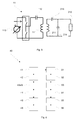
- a calibrator unit 20 for calibrating a test unit 10 comprises an electrical circuit 21 comprising a secondary receiver coil 211 for receiving electrical power of a certain frequency from a primary transmitter coil of the test unit 10 in use.
- the electrical circuit 21 further comprises a resistor 212 connected in series with the secondary receiver coil and having a well defined resistance R CAL .
- the calibrator unit 20 comprises a calibrator control unit 22.
- the calibrator control unit may comprise a processor and a memory.
- the calibrator control unit 22 is configured to, for each power frequency of the inductive power received, receive a voltage measurement of U CAL (f) over the precision resistor 212.
- the measured voltage U CAL (f) may be conducted by means of a high resolution ADC, similarly to that of the test unit.
- an external voltmeter (not shown) may be connected to the precision resistor 212.
- the voltage amplification constant is derived such that the product of K U-CAL (f) and the voltage measured by the ADC is equal to the reference voltage measured by the voltmeter.
- the calibrator control unit 22 is further configured to calculate the actual inductive power P TX-ACTUAL (f) received by the secondary receiver coil 211 based solely on the measured voltage and resistance of the resistor by using Ohm's Law.
- the calibrator control unit 22 is configured to transmit a signal, containing data comprising information of the calculated actual electrical power P TX-ACTUAL received by the secondary receiver coil, to the test unit 10 in use.
- Fig 5 shows a general electrical circuit 11 of a test unit 10 and the electrical circuit 21 of a calibrator unit 20 when the test unit 10 is inductively coupled to the calibrator unit 20 according to an embodiment.
- a method 40 for testing inductive power charging of the mobile device 30, using the test unit 10 having a precisely calibrated power output is provided.
- Steps 41 thru 46 relates to the calibration mode of the test unit 10. The method comprises the steps of:
- the steps 51 thru 56 relates to the calibration mode of the test unit 10. Hence, the method further comprises the steps of:
- K U-MDT denotes the derived voltage amplification constant
- U ⁇ t(f) denotes the time compensated measured voltage U
- I denotes the measured current
- K I-MDT (f) denotes the derived current amplification
- R ESR (f) denotes a known transmitter coil equivalent series resistance for power frequency f
- P TX f U * K U - MDT f * I ⁇ t f * K I - MDT f - R ESR f * I 2 * K I - MDT f 2 , wherein
- K U-MDT denotes the derived voltage amplification constant
- I ⁇ t(f) denotes the time compensated measured current I
- U denotes the measured voltage
- K I-MDT (f) denotes the derived current amplification
- R ESR (f) denotes a known transmitter coil equivalent series resistance for power frequency f
Landscapes
- Engineering & Computer Science (AREA)
- Computer Networks & Wireless Communication (AREA)
- Power Engineering (AREA)
- Signal Processing (AREA)
- Physics & Mathematics (AREA)
- General Physics & Mathematics (AREA)
- Charge And Discharge Circuits For Batteries Or The Like (AREA)
- Testing Electric Properties And Detecting Electric Faults (AREA)
Applications Claiming Priority (1)
| Application Number | Priority Date | Filing Date | Title |
|---|---|---|---|
| SE1451610A SE541339C2 (en) | 2014-12-19 | 2014-12-19 | A mobile device tester for precise inductive power measurement and a calibration unit therefor |
Publications (2)
| Publication Number | Publication Date |
|---|---|
| EP3035490A1 true EP3035490A1 (fr) | 2016-06-22 |
| EP3035490B1 EP3035490B1 (fr) | 2019-08-14 |
Family
ID=55023942
Family Applications (1)
| Application Number | Title | Priority Date | Filing Date |
|---|---|---|---|
| EP15201227.4A Active EP3035490B1 (fr) | 2014-12-19 | 2015-12-18 | Testeur de dispositif mobile pour mesure de puissance inductive précise et unité d'étalonnage correspondant |
Country Status (7)
| Country | Link |
|---|---|
| US (1) | US10317440B2 (fr) |
| EP (1) | EP3035490B1 (fr) |
| JP (1) | JP6659349B2 (fr) |
| KR (1) | KR101901837B1 (fr) |
| CN (1) | CN105717389B (fr) |
| SE (1) | SE541339C2 (fr) |
| TW (1) | TWI701887B (fr) |
Cited By (2)
| Publication number | Priority date | Publication date | Assignee | Title |
|---|---|---|---|---|
| EP4089432A1 (fr) | 2021-05-14 | 2022-11-16 | ElectDis AB | Procédés et systèmes permettant de fournir une référence secondaire pour les mesures de transfert d'énergie sans fil et d'évaluer un dispositif de mesure d'énergie sans fil |
| WO2023153995A1 (fr) * | 2022-02-11 | 2023-08-17 | Electdis Ab | Procédé d'étalonnage de puissance |
Families Citing this family (6)
| Publication number | Priority date | Publication date | Assignee | Title |
|---|---|---|---|---|
| SE541339C2 (en) * | 2014-12-19 | 2019-07-16 | Nok9 Ip Ab | A mobile device tester for precise inductive power measurement and a calibration unit therefor |
| US10116145B2 (en) * | 2015-10-16 | 2018-10-30 | uBeam Inc. | Performance adjustment for wireless power transfer devices |
| EP3379268B1 (fr) * | 2017-03-23 | 2022-05-04 | Rohde & Schwarz GmbH & Co. KG | Dispositif d'essai et de mesure et procédé de fonctionnement |
| EP3547487B1 (fr) * | 2018-03-29 | 2020-03-25 | NOK9 ip AB | Dispositif de test pour tester un dispositif émetteur d'énergie sans fil et procédé associé |
| TWI806675B (zh) * | 2022-06-23 | 2023-06-21 | 瑞昱半導體股份有限公司 | 發射器與功率校正方法 |
| CN121027611B (zh) * | 2025-10-31 | 2025-12-30 | 青岛英利达新能源有限公司 | 一种提高电能表电流采样精度的补偿方法 |
Citations (6)
| Publication number | Priority date | Publication date | Assignee | Title |
|---|---|---|---|---|
| US20110196544A1 (en) * | 2010-02-08 | 2011-08-11 | Access Business Group International Llc | Input parasitic metal detection |
| WO2012109610A1 (fr) * | 2011-02-11 | 2012-08-16 | Qualcomm Incorporated | Systèmes et procédés pour étalonner un transmetteur d'énergie sans fil |
| US20120326658A1 (en) * | 2011-06-24 | 2012-12-27 | Samsung Electro-Mechanics Company, Ltd. | Calibration and assignment processes in wireless power transfer systems |
| US20130026847A1 (en) * | 2011-07-28 | 2013-01-31 | Samsung Electronics Co., Ltd. | Wireless power transmission system, method and apparatus for tracking resonance frequency in wireless power transmission system |
| US20140001877A1 (en) * | 2004-05-11 | 2014-01-02 | Access Business Group International Llc | Controlling inductive power transfer system |
| WO2014060871A1 (fr) * | 2012-10-16 | 2014-04-24 | Koninklijke Philips N.V. | Transfert de puissance inductive sans fil |
Family Cites Families (12)
| Publication number | Priority date | Publication date | Assignee | Title |
|---|---|---|---|---|
| GB2414120B (en) * | 2004-05-11 | 2008-04-02 | Splashpower Ltd | Controlling inductive power transfer systems |
| US7952322B2 (en) * | 2006-01-31 | 2011-05-31 | Mojo Mobility, Inc. | Inductive power source and charging system |
| DE102008034109B4 (de) * | 2008-07-21 | 2016-10-13 | Dspace Digital Signal Processing And Control Engineering Gmbh | Schaltung zur Nachbildung einer elektrischen Last |
| PL2340595T3 (pl) * | 2008-10-20 | 2013-01-31 | Siemens Ag | Urządzenie i sposób do kompensacji mocy biernej transformatora probierczego |
| WO2012112461A2 (fr) * | 2011-02-14 | 2012-08-23 | Kogel Frank William | Procédé de configuration de paramètre pour des éléments d'un convertisseur de correction de facteur de puissance |
| US20140252866A1 (en) * | 2011-11-03 | 2014-09-11 | Jim Walsh | Presence and range detection of wireless power receiving devices and method thereof |
| CN103545882B (zh) * | 2013-10-11 | 2015-07-22 | 华为技术有限公司 | 电池在位检测方法、装置及充电系统 |
| US9391470B2 (en) * | 2013-11-06 | 2016-07-12 | Blackberry Limited | Energy transfer optimization by detecting and mitigating magnetic saturation in wireless charging with foreign object detection |
| CN103728533B (zh) * | 2014-01-16 | 2016-05-18 | 北京航空航天大学 | 一种大功率非接触充电系统主电路故障检测装置 |
| SE541339C2 (en) * | 2014-12-19 | 2019-07-16 | Nok9 Ip Ab | A mobile device tester for precise inductive power measurement and a calibration unit therefor |
| US9985481B2 (en) * | 2016-03-28 | 2018-05-29 | Intel IP Corporation | Dynamic power adjustment mechanism for mitigating wireless power interference |
| EP3244542B1 (fr) * | 2016-05-09 | 2019-07-24 | Intel IP Corporation | Procédé et dispositif pour atténuer une interférence due à un signal de charge sans fil |
-
2014
- 2014-12-19 SE SE1451610A patent/SE541339C2/en unknown
-
2015
- 2015-12-18 TW TW104142764A patent/TWI701887B/zh active
- 2015-12-18 JP JP2015247677A patent/JP6659349B2/ja active Active
- 2015-12-18 US US14/974,693 patent/US10317440B2/en active Active
- 2015-12-18 KR KR1020150182047A patent/KR101901837B1/ko active Active
- 2015-12-18 EP EP15201227.4A patent/EP3035490B1/fr active Active
- 2015-12-21 CN CN201510965280.4A patent/CN105717389B/zh active Active
Patent Citations (6)
| Publication number | Priority date | Publication date | Assignee | Title |
|---|---|---|---|---|
| US20140001877A1 (en) * | 2004-05-11 | 2014-01-02 | Access Business Group International Llc | Controlling inductive power transfer system |
| US20110196544A1 (en) * | 2010-02-08 | 2011-08-11 | Access Business Group International Llc | Input parasitic metal detection |
| WO2012109610A1 (fr) * | 2011-02-11 | 2012-08-16 | Qualcomm Incorporated | Systèmes et procédés pour étalonner un transmetteur d'énergie sans fil |
| US20120326658A1 (en) * | 2011-06-24 | 2012-12-27 | Samsung Electro-Mechanics Company, Ltd. | Calibration and assignment processes in wireless power transfer systems |
| US20130026847A1 (en) * | 2011-07-28 | 2013-01-31 | Samsung Electronics Co., Ltd. | Wireless power transmission system, method and apparatus for tracking resonance frequency in wireless power transmission system |
| WO2014060871A1 (fr) * | 2012-10-16 | 2014-04-24 | Koninklijke Philips N.V. | Transfert de puissance inductive sans fil |
Cited By (4)
| Publication number | Priority date | Publication date | Assignee | Title |
|---|---|---|---|---|
| EP4089432A1 (fr) | 2021-05-14 | 2022-11-16 | ElectDis AB | Procédés et systèmes permettant de fournir une référence secondaire pour les mesures de transfert d'énergie sans fil et d'évaluer un dispositif de mesure d'énergie sans fil |
| WO2022238498A1 (fr) | 2021-05-14 | 2022-11-17 | Electdis Ab | Procédés et systèmes pour fournir une référence secondaire pour évaluer une précision de mesure de puissance sans fil, et pour évaluer une précision de mesure de puissance d'un dispositif de mesure de puissance sans fil à l'essai |
| WO2023153995A1 (fr) * | 2022-02-11 | 2023-08-17 | Electdis Ab | Procédé d'étalonnage de puissance |
| EP4476555A4 (fr) * | 2022-02-11 | 2026-02-18 | Electdis Ab | Procédé d'étalonnage de puissance |
Also Published As
| Publication number | Publication date |
|---|---|
| TW201633659A (zh) | 2016-09-16 |
| JP6659349B2 (ja) | 2020-03-04 |
| EP3035490B1 (fr) | 2019-08-14 |
| SE1451610A1 (en) | 2016-06-20 |
| TWI701887B (zh) | 2020-08-11 |
| CN105717389A (zh) | 2016-06-29 |
| KR20160075369A (ko) | 2016-06-29 |
| US10317440B2 (en) | 2019-06-11 |
| KR101901837B1 (ko) | 2018-11-07 |
| JP2016140234A (ja) | 2016-08-04 |
| US20160178676A1 (en) | 2016-06-23 |
| SE541339C2 (en) | 2019-07-16 |
| CN105717389B (zh) | 2020-09-15 |
Similar Documents
| Publication | Publication Date | Title |
|---|---|---|
| EP3035490B1 (fr) | Testeur de dispositif mobile pour mesure de puissance inductive précise et unité d'étalonnage correspondant | |
| JP2016140234A5 (fr) | ||
| JP5869497B2 (ja) | 入力寄生金属の検出 | |
| US20210273492A1 (en) | Enhanced method for foreign objects detection | |
| US20110136449A1 (en) | Testing System and Power Calibration Method Thereof | |
| KR102038814B1 (ko) | 임피던스 추정 장치 | |
| EP3215860B1 (fr) | Systèmes et procédés de mesure et de détermination de paramètres de bruit | |
| JP2013519355A5 (fr) | ||
| US9544070B2 (en) | Frequency-converting sensor and system for providing a radio frequency signal parameter | |
| US8400165B2 (en) | Power calibration system | |
| CN107861091B (zh) | 一种基于动态电能校准器的动态性能溯源方法 | |
| US20220416588A1 (en) | Wireless charging method, device and system | |
| CN104535954A (zh) | 有源泄露电流测试仪的校准装置 | |
| JP6834849B2 (ja) | インピーダンス推定装置 | |
| US10436827B2 (en) | Measurement device and method for measuring the impedance of a device under test | |
| US10718635B2 (en) | Contact detection circuit of four-terminal measurement device | |
| CN103929770B (zh) | 校正待测装置以无线进行通信的方法 | |
| CN103698044A (zh) | 基于卫星温度遥测的测温误差分析方法 | |
| CN107589396B (zh) | 一种基于常规电能校准器的动态性能溯源方法 | |
| US10345420B2 (en) | Method, a calibration unit and a system for determining system errors and power values for the calibration of a network analyser | |
| US10120008B2 (en) | Method and apparatus for estimating the noise introduced by a device | |
| JP2016099194A (ja) | 無線周波数パラメーターの校正方法 | |
| US11480536B2 (en) | Method and sensor for determining the permittivity of a cell population | |
| RU2468334C1 (ru) | Способ коррекции результатов измерения тензометрическим мостовым датчиком с инструментальным усилителем | |
| KR100626207B1 (ko) | 자체 송수신 장치를 이용한 케이블 캘리브레이션 방법 및그 장치와, 그 방법을 포함하는 프로그램을 저장한기록매체 |
Legal Events
| Date | Code | Title | Description |
|---|---|---|---|
| PUAI | Public reference made under article 153(3) epc to a published international application that has entered the european phase |
Free format text: ORIGINAL CODE: 0009012 |
|
| AK | Designated contracting states |
Kind code of ref document: A1 Designated state(s): AL AT BE BG CH CY CZ DE DK EE ES FI FR GB GR HR HU IE IS IT LI LT LU LV MC MK MT NL NO PL PT RO RS SE SI SK SM TR |
|
| AX | Request for extension of the european patent |
Extension state: BA ME |
|
| STAA | Information on the status of an ep patent application or granted ep patent |
Free format text: STATUS: REQUEST FOR EXAMINATION WAS MADE |
|
| 17P | Request for examination filed |
Effective date: 20161220 |
|
| RBV | Designated contracting states (corrected) |
Designated state(s): AL AT BE BG CH CY CZ DE DK EE ES FI FR GB GR HR HU IE IS IT LI LT LU LV MC MK MT NL NO PL PT RO RS SE SI SK SM TR |
|
| STAA | Information on the status of an ep patent application or granted ep patent |
Free format text: STATUS: EXAMINATION IS IN PROGRESS |
|
| 17Q | First examination report despatched |
Effective date: 20180329 |
|
| RIC1 | Information provided on ipc code assigned before grant |
Ipc: G01R 35/04 20060101ALN20190130BHEP Ipc: G01R 31/40 20140101ALN20190130BHEP Ipc: H04B 5/00 20060101ALN20190130BHEP Ipc: H02J 50/10 20160101AFI20190130BHEP Ipc: H02J 50/12 20160101ALI20190130BHEP Ipc: G01R 35/00 20060101ALI20190130BHEP Ipc: H02J 7/02 20160101ALN20190130BHEP Ipc: G01R 31/28 20060101ALN20190130BHEP |
|
| RIC1 | Information provided on ipc code assigned before grant |
Ipc: H02J 50/10 20160101AFI20190206BHEP Ipc: G01R 31/40 20140101ALN20190206BHEP Ipc: H02J 50/12 20160101ALI20190206BHEP Ipc: H02J 7/02 20160101ALN20190206BHEP Ipc: G01R 31/28 20060101ALN20190206BHEP Ipc: G01R 35/04 20060101ALN20190206BHEP Ipc: H04B 5/00 20060101ALN20190206BHEP Ipc: G01R 35/00 20060101ALI20190206BHEP |
|
| GRAP | Despatch of communication of intention to grant a patent |
Free format text: ORIGINAL CODE: EPIDOSNIGR1 |
|
| STAA | Information on the status of an ep patent application or granted ep patent |
Free format text: STATUS: GRANT OF PATENT IS INTENDED |
|
| INTG | Intention to grant announced |
Effective date: 20190320 |
|
| RAP1 | Party data changed (applicant data changed or rights of an application transferred) |
Owner name: NOK9 IP AB |
|
| GRAS | Grant fee paid |
Free format text: ORIGINAL CODE: EPIDOSNIGR3 |
|
| GRAA | (expected) grant |
Free format text: ORIGINAL CODE: 0009210 |
|
| STAA | Information on the status of an ep patent application or granted ep patent |
Free format text: STATUS: THE PATENT HAS BEEN GRANTED |
|
| AK | Designated contracting states |
Kind code of ref document: B1 Designated state(s): AL AT BE BG CH CY CZ DE DK EE ES FI FR GB GR HR HU IE IS IT LI LT LU LV MC MK MT NL NO PL PT RO RS SE SI SK SM TR |
|
| REG | Reference to a national code |
Ref country code: GB Ref legal event code: FG4D |
|
| REG | Reference to a national code |
Ref country code: CH Ref legal event code: EP Ref country code: AT Ref legal event code: REF Ref document number: 1168170 Country of ref document: AT Kind code of ref document: T Effective date: 20190815 |
|
| REG | Reference to a national code |
Ref country code: IE Ref legal event code: FG4D |
|
| REG | Reference to a national code |
Ref country code: DE Ref legal event code: R096 Ref document number: 602015035742 Country of ref document: DE |
|
| REG | Reference to a national code |
Ref country code: NL Ref legal event code: MP Effective date: 20190814 |
|
| REG | Reference to a national code |
Ref country code: LT Ref legal event code: MG4D |
|
| PG25 | Lapsed in a contracting state [announced via postgrant information from national office to epo] |
Ref country code: NO Free format text: LAPSE BECAUSE OF FAILURE TO SUBMIT A TRANSLATION OF THE DESCRIPTION OR TO PAY THE FEE WITHIN THE PRESCRIBED TIME-LIMIT Effective date: 20191114 Ref country code: NL Free format text: LAPSE BECAUSE OF FAILURE TO SUBMIT A TRANSLATION OF THE DESCRIPTION OR TO PAY THE FEE WITHIN THE PRESCRIBED TIME-LIMIT Effective date: 20190814 Ref country code: SE Free format text: LAPSE BECAUSE OF FAILURE TO SUBMIT A TRANSLATION OF THE DESCRIPTION OR TO PAY THE FEE WITHIN THE PRESCRIBED TIME-LIMIT Effective date: 20190814 Ref country code: BG Free format text: LAPSE BECAUSE OF FAILURE TO SUBMIT A TRANSLATION OF THE DESCRIPTION OR TO PAY THE FEE WITHIN THE PRESCRIBED TIME-LIMIT Effective date: 20191114 Ref country code: FI Free format text: LAPSE BECAUSE OF FAILURE TO SUBMIT A TRANSLATION OF THE DESCRIPTION OR TO PAY THE FEE WITHIN THE PRESCRIBED TIME-LIMIT Effective date: 20190814 Ref country code: LT Free format text: LAPSE BECAUSE OF FAILURE TO SUBMIT A TRANSLATION OF THE DESCRIPTION OR TO PAY THE FEE WITHIN THE PRESCRIBED TIME-LIMIT Effective date: 20190814 Ref country code: HR Free format text: LAPSE BECAUSE OF FAILURE TO SUBMIT A TRANSLATION OF THE DESCRIPTION OR TO PAY THE FEE WITHIN THE PRESCRIBED TIME-LIMIT Effective date: 20190814 Ref country code: PT Free format text: LAPSE BECAUSE OF FAILURE TO SUBMIT A TRANSLATION OF THE DESCRIPTION OR TO PAY THE FEE WITHIN THE PRESCRIBED TIME-LIMIT Effective date: 20191216 |
|
| REG | Reference to a national code |
Ref country code: AT Ref legal event code: MK05 Ref document number: 1168170 Country of ref document: AT Kind code of ref document: T Effective date: 20190814 |
|
| PG25 | Lapsed in a contracting state [announced via postgrant information from national office to epo] |
Ref country code: ES Free format text: LAPSE BECAUSE OF FAILURE TO SUBMIT A TRANSLATION OF THE DESCRIPTION OR TO PAY THE FEE WITHIN THE PRESCRIBED TIME-LIMIT Effective date: 20190814 Ref country code: GR Free format text: LAPSE BECAUSE OF FAILURE TO SUBMIT A TRANSLATION OF THE DESCRIPTION OR TO PAY THE FEE WITHIN THE PRESCRIBED TIME-LIMIT Effective date: 20191115 Ref country code: LV Free format text: LAPSE BECAUSE OF FAILURE TO SUBMIT A TRANSLATION OF THE DESCRIPTION OR TO PAY THE FEE WITHIN THE PRESCRIBED TIME-LIMIT Effective date: 20190814 Ref country code: IS Free format text: LAPSE BECAUSE OF FAILURE TO SUBMIT A TRANSLATION OF THE DESCRIPTION OR TO PAY THE FEE WITHIN THE PRESCRIBED TIME-LIMIT Effective date: 20191214 Ref country code: RS Free format text: LAPSE BECAUSE OF FAILURE TO SUBMIT A TRANSLATION OF THE DESCRIPTION OR TO PAY THE FEE WITHIN THE PRESCRIBED TIME-LIMIT Effective date: 20190814 Ref country code: AL Free format text: LAPSE BECAUSE OF FAILURE TO SUBMIT A TRANSLATION OF THE DESCRIPTION OR TO PAY THE FEE WITHIN THE PRESCRIBED TIME-LIMIT Effective date: 20190814 |
|
| PG25 | Lapsed in a contracting state [announced via postgrant information from national office to epo] |
Ref country code: TR Free format text: LAPSE BECAUSE OF FAILURE TO SUBMIT A TRANSLATION OF THE DESCRIPTION OR TO PAY THE FEE WITHIN THE PRESCRIBED TIME-LIMIT Effective date: 20190814 |
|
| PG25 | Lapsed in a contracting state [announced via postgrant information from national office to epo] |
Ref country code: EE Free format text: LAPSE BECAUSE OF FAILURE TO SUBMIT A TRANSLATION OF THE DESCRIPTION OR TO PAY THE FEE WITHIN THE PRESCRIBED TIME-LIMIT Effective date: 20190814 Ref country code: PL Free format text: LAPSE BECAUSE OF FAILURE TO SUBMIT A TRANSLATION OF THE DESCRIPTION OR TO PAY THE FEE WITHIN THE PRESCRIBED TIME-LIMIT Effective date: 20190814 Ref country code: DK Free format text: LAPSE BECAUSE OF FAILURE TO SUBMIT A TRANSLATION OF THE DESCRIPTION OR TO PAY THE FEE WITHIN THE PRESCRIBED TIME-LIMIT Effective date: 20190814 Ref country code: RO Free format text: LAPSE BECAUSE OF FAILURE TO SUBMIT A TRANSLATION OF THE DESCRIPTION OR TO PAY THE FEE WITHIN THE PRESCRIBED TIME-LIMIT Effective date: 20190814 Ref country code: IT Free format text: LAPSE BECAUSE OF FAILURE TO SUBMIT A TRANSLATION OF THE DESCRIPTION OR TO PAY THE FEE WITHIN THE PRESCRIBED TIME-LIMIT Effective date: 20190814 Ref country code: AT Free format text: LAPSE BECAUSE OF FAILURE TO SUBMIT A TRANSLATION OF THE DESCRIPTION OR TO PAY THE FEE WITHIN THE PRESCRIBED TIME-LIMIT Effective date: 20190814 |
|
| PG25 | Lapsed in a contracting state [announced via postgrant information from national office to epo] |
Ref country code: CZ Free format text: LAPSE BECAUSE OF FAILURE TO SUBMIT A TRANSLATION OF THE DESCRIPTION OR TO PAY THE FEE WITHIN THE PRESCRIBED TIME-LIMIT Effective date: 20190814 Ref country code: SK Free format text: LAPSE BECAUSE OF FAILURE TO SUBMIT A TRANSLATION OF THE DESCRIPTION OR TO PAY THE FEE WITHIN THE PRESCRIBED TIME-LIMIT Effective date: 20190814 Ref country code: SM Free format text: LAPSE BECAUSE OF FAILURE TO SUBMIT A TRANSLATION OF THE DESCRIPTION OR TO PAY THE FEE WITHIN THE PRESCRIBED TIME-LIMIT Effective date: 20190814 Ref country code: IS Free format text: LAPSE BECAUSE OF FAILURE TO SUBMIT A TRANSLATION OF THE DESCRIPTION OR TO PAY THE FEE WITHIN THE PRESCRIBED TIME-LIMIT Effective date: 20200224 |
|
| REG | Reference to a national code |
Ref country code: DE Ref legal event code: R097 Ref document number: 602015035742 Country of ref document: DE |
|
| PLBE | No opposition filed within time limit |
Free format text: ORIGINAL CODE: 0009261 |
|
| STAA | Information on the status of an ep patent application or granted ep patent |
Free format text: STATUS: NO OPPOSITION FILED WITHIN TIME LIMIT |
|
| PG2D | Information on lapse in contracting state deleted |
Ref country code: IS |
|
| REG | Reference to a national code |
Ref country code: CH Ref legal event code: PL |
|
| 26N | No opposition filed |
Effective date: 20200603 |
|
| REG | Reference to a national code |
Ref country code: BE Ref legal event code: MM Effective date: 20191231 |
|
| PG25 | Lapsed in a contracting state [announced via postgrant information from national office to epo] |
Ref country code: SI Free format text: LAPSE BECAUSE OF FAILURE TO SUBMIT A TRANSLATION OF THE DESCRIPTION OR TO PAY THE FEE WITHIN THE PRESCRIBED TIME-LIMIT Effective date: 20190814 Ref country code: MC Free format text: LAPSE BECAUSE OF FAILURE TO SUBMIT A TRANSLATION OF THE DESCRIPTION OR TO PAY THE FEE WITHIN THE PRESCRIBED TIME-LIMIT Effective date: 20190814 |
|
| REG | Reference to a national code |
Ref country code: DE Ref legal event code: R081 Ref document number: 602015035742 Country of ref document: DE Owner name: ELECTDIS AB, SE Free format text: FORMER OWNER: NOK9 IP AB, MALMOE, SE |
|
| PG25 | Lapsed in a contracting state [announced via postgrant information from national office to epo] |
Ref country code: LU Free format text: LAPSE BECAUSE OF NON-PAYMENT OF DUE FEES Effective date: 20191218 Ref country code: IE Free format text: LAPSE BECAUSE OF NON-PAYMENT OF DUE FEES Effective date: 20191218 |
|
| PG25 | Lapsed in a contracting state [announced via postgrant information from national office to epo] |
Ref country code: CH Free format text: LAPSE BECAUSE OF NON-PAYMENT OF DUE FEES Effective date: 20191231 Ref country code: BE Free format text: LAPSE BECAUSE OF NON-PAYMENT OF DUE FEES Effective date: 20191231 Ref country code: LI Free format text: LAPSE BECAUSE OF NON-PAYMENT OF DUE FEES Effective date: 20191231 |
|
| PG25 | Lapsed in a contracting state [announced via postgrant information from national office to epo] |
Ref country code: CY Free format text: LAPSE BECAUSE OF FAILURE TO SUBMIT A TRANSLATION OF THE DESCRIPTION OR TO PAY THE FEE WITHIN THE PRESCRIBED TIME-LIMIT Effective date: 20190814 |
|
| PG25 | Lapsed in a contracting state [announced via postgrant information from national office to epo] |
Ref country code: HU Free format text: LAPSE BECAUSE OF FAILURE TO SUBMIT A TRANSLATION OF THE DESCRIPTION OR TO PAY THE FEE WITHIN THE PRESCRIBED TIME-LIMIT; INVALID AB INITIO Effective date: 20151218 Ref country code: MT Free format text: LAPSE BECAUSE OF FAILURE TO SUBMIT A TRANSLATION OF THE DESCRIPTION OR TO PAY THE FEE WITHIN THE PRESCRIBED TIME-LIMIT Effective date: 20190814 |
|
| PG25 | Lapsed in a contracting state [announced via postgrant information from national office to epo] |
Ref country code: MK Free format text: LAPSE BECAUSE OF FAILURE TO SUBMIT A TRANSLATION OF THE DESCRIPTION OR TO PAY THE FEE WITHIN THE PRESCRIBED TIME-LIMIT Effective date: 20190814 |
|
| P01 | Opt-out of the competence of the unified patent court (upc) registered |
Effective date: 20230421 |
|
| PGFP | Annual fee paid to national office [announced via postgrant information from national office to epo] |
Ref country code: DE Payment date: 20251212 Year of fee payment: 11 |
|
| PGFP | Annual fee paid to national office [announced via postgrant information from national office to epo] |
Ref country code: GB Payment date: 20251209 Year of fee payment: 11 |
|
| PGFP | Annual fee paid to national office [announced via postgrant information from national office to epo] |
Ref country code: FR Payment date: 20251209 Year of fee payment: 11 |