EP3035534A1 - Tastatur mit verbesserter zuverlässigkeit - Google Patents
Tastatur mit verbesserter zuverlässigkeit Download PDFInfo
- Publication number
- EP3035534A1 EP3035534A1 EP15200021.2A EP15200021A EP3035534A1 EP 3035534 A1 EP3035534 A1 EP 3035534A1 EP 15200021 A EP15200021 A EP 15200021A EP 3035534 A1 EP3035534 A1 EP 3035534A1
- Authority
- EP
- European Patent Office
- Prior art keywords
- waveguide
- face
- wave
- keyboard
- plunger
- Prior art date
- Legal status (The legal status is an assumption and is not a legal conclusion. Google has not performed a legal analysis and makes no representation as to the accuracy of the status listed.)
- Granted
Links
Images

Classifications
-
- G—PHYSICS
- G06—COMPUTING OR CALCULATING; COUNTING
- G06F—ELECTRIC DIGITAL DATA PROCESSING
- G06F3/00—Input arrangements for transferring data to be processed into a form capable of being handled by the computer; Output arrangements for transferring data from processing unit to output unit, e.g. interface arrangements
- G06F3/01—Input arrangements or combined input and output arrangements for interaction between user and computer
- G06F3/02—Input arrangements using manually operated switches, e.g. using keyboards or dials
- G06F3/0202—Constructional details or processes of manufacture of the input device
-
- G—PHYSICS
- G06—COMPUTING OR CALCULATING; COUNTING
- G06F—ELECTRIC DIGITAL DATA PROCESSING
- G06F3/00—Input arrangements for transferring data to be processed into a form capable of being handled by the computer; Output arrangements for transferring data from processing unit to output unit, e.g. interface arrangements
- G06F3/01—Input arrangements or combined input and output arrangements for interaction between user and computer
- G06F3/02—Input arrangements using manually operated switches, e.g. using keyboards or dials
- G06F3/023—Arrangements for converting discrete items of information into a coded form, e.g. arrangements for interpreting keyboard generated codes as alphanumeric codes, operand codes or instruction codes
-
- H—ELECTRICITY
- H03—ELECTRONIC CIRCUITRY
- H03K—PULSE TECHNIQUE
- H03K17/00—Electronic switching or gating, i.e. not by contact-making and –breaking
- H03K17/94—Electronic switching or gating, i.e. not by contact-making and –breaking characterised by the way in which the control signals are generated
- H03K17/965—Switches controlled by moving an element forming part of the switch
- H03K17/968—Switches controlled by moving an element forming part of the switch using opto-electronic devices
- H03K17/969—Switches controlled by moving an element forming part of the switch using opto-electronic devices having a plurality of control members, e.g. keyboard
Definitions
- the invention relates to a keyboard whose reliability is improved. Keyboards are present in many electronic equipment. They are used for a user to enter data.
- Known keyboards include keys intended to be manipulated by a user.
- the operation of a key causes that of a switch for making an electrical connection between two points in order to pass or not an electrical signal depending on the pressing of the key.
- the switch comprises for example a metal dome integral with a printed circuit.
- the dome is destined to collapse under the effect of pressing the key. Collapsing, the dome creates an electrical contact on the printed circuit.
- the invention provides a solution to this problem by providing a keyboard much simpler to achieve.
- the keyboard is made around an optical waveguide fulfilling many functions such as decoupling the movement of the key of the formation of a signal representative of the movement of the key.
- This physical isolation protects the part forming the signals of dust or liquids that can pollute the keys.
- the protection of keyboards vis-à-vis electromagnetic disturbances can cause problems. Indeed, in conventional keyboards, the electrical signals passing through the switches can be disturbed or disrupt other equipment. The presence of moving parts of the keyboards can make it difficult to achieve shielding screens to isolate signals from the external environment. The presence of the waveguide solves this problem easily.
- the keyboard advantageously comprises an electric shielding screen disposed on one of the faces of the waveguide, the shielding screen being transparent to the wave propagated in the waveguide.
- the keyboard comprises at least one cover for protecting each of the sensors of a parasite wave not coming from the frustration caused by the contact of the plunger associated with the sensor.
- the cover may be formed by a mask that is opaque to the wave propagating in the waveguide, the mask covering the second face, with the exception of a hole centered opposite an area intended to receive the contact of the plunger on the first side.
- the altered zone may include means for focusing the light extracted by the first face around a direction perpendicular to the plane of the waveguide.
- the keyboard may include first and second wave sources propagating in the waveguide and each transmitting in a wavelength band, the two bands being distinct.
- the sensor is then configured to detect a wave of the band of the first source and the band of the second source is used to exit the waveguide by the altered zone.
- the keyboard comprises a light source controlled by the representative signal and allowing feedback to the user according to the contact of the plunger with the first face of the waveguide.
- the light source for the feedback can be arranged to emit light perpendicular to the waveguide through it.
- the light source allowing the feedback can emit in a wavelength band distinct from that for which the sensor is configured.
- the figure 1 represents a keyboard 10 comprising two keys 11 and 12.
- a keyboard according to the invention may comprise a greater number of keys, which is for example the case in a keyboard for entering alphanumeric characters.
- the invention can be implemented in a keyboard having only one key.
- the keys 11 and 12 are movable in translation relative to a support 13 for example plan and attached to an electronic equipment. Solidarity of each key 11 and 12, a plunger, respectively 14 and 15 follows the translational movement of the key in question.
- the key and the plunger associated with it can be formed by the same mechanical part or by two separate mechanical parts fixed to one another. One can, however, distinguish the function of the key which is to receive the support of a user and the function of the diver who is to transmit this support.
- the plungers 14 and 15 can move in translation each along an axis, respectively 16 and 17, these axes being parallel to each other and perpendicular to the support 13.
- the axes 16 and 17 are shown vertically and the movement of the keys 11 and 12 is from top to bottom along their respective axis.
- the displacement of each of the keys 11 and 12 is limited upwards by a stop, respectively 18 and 19, formed in the support 13.
- Each of the plungers 14 and 15 bears against its respective abutment.
- a return spring, respectively 20 and 21 can push the plunger towards its respective stop. In this position, pressing against its stop, the key and its plunger are in a rest position, that is to say a position not activated by a user.
- the corresponding plunger leaves its support against its stop and pushes the associated return spring.
- the support 13 can be formed of two mechanical parts 13a and 13b fixed together to allow the mounting of the plunger and the corresponding spring.
- the return spring 20 or 21 exerts on the corresponding plunger 14 or 15 a force proportional to its displacement. It is possible to provide a tactile feedback to the non-proportional user, having for example a force / displacement curve having a maximum.
- This type of curve can be obtained for example by means of a "hard point" in the displacement of the plunger.
- This hard point may include a cam made on the plunger.
- a cam follower such as a ball, which can move horizontally relative to the support 13, is held in abutment against the cam by means of a spring.
- the shape of the cam defines the desired effort / displacement curve.
- the keyboard 10 comprises a plane waveguide 20 substantially perpendicular to the axes 16 and 17.
- the waveguide 20 serves to guide an electromagnetic wave, such as for example a light wave, in a central layer 24, bounded by two external faces. 22 and 23.
- the refractive index of the central layer 24 is greater than that of the medium in which the waveguide 20 is placed, such as air. This gives a total reflection of the wave propagating in the central layer 24 on the two outer faces 22 and 23.
- the waveguide 20 is for example made of glass or poly methacrylate methyl known by the abbreviated name PMMA , from its abbreviation Anglo-Saxon: "Polymethyl methacrylate”.
- the plunger 14 or 15 can move between two positions, one in contact with the face 22 and the other at a distance from the face 22 and bearing against its abutment 18 or 19.
- the plunger 14 is shown at a distance from the face 22 and the plunger 15 is shown in contact with the face 22.
- the contact of the plunger 15 on the face 22 causes a local frustration of the reflection of the wave in the guide 20. This frustration causes a backscattering of the wave that passes through the guide 20 perpendicular to its plane. Part of the wave then passes through the face 23 when the plunger 15 is in contact with the face 22. In the absence of contact between the plunger and the face 22, no frustration occurs and the reflection of the wave is total on the two faces 22 and 23.
- the keyboard 10 comprises a printed circuit 25 arranged parallel to the waveguide 20 on the side of the face 23.
- the printed circuit carries a sensor 26 disposed opposite the plunger 14 on the axis 16 and a sensor 27 disposed facing the plunger
- the sensors 26 and 27 are, for example, photodiodes sensitive to the light wave propagated in the waveguide 20.
- the sensors 26 and 27 form a signal representative of the support of the respective keys 11 and 12 by a user.
- the representative signal is electrical and can be processed by other components arranged on the printed circuit 25.
- the current from a photodiode can be processed by means of a voltage current converter followed by an operational amplifier comparing the voltage generated by the converter at a threshold.
- a binary and available signal representing the detection of a key press for one of the levels and the absence of support for the other binary level.
- other types of sensors can be implemented in the context of the invention, such as for example a sensor delivering an optical signal.
- the figure 2 represents a simulation of the backscattered wave for simultaneous support on four adjacent keys of the keyboard 10.
- the backscattered wave during the contact of a plunger on the face 22 is emitted around a direction perpendicular to the plane of the waveguide 20.
- the various divers are spotted 35 on the figure 2 .
- the intensity of the backscattered wave is maximum in the direction perpendicular to the plane of the waveguide 20 and decreases for directions away from the perpendicular direction.
- lines represent the presence of a backscattered wave. The closer the traints are, the greater the intensity of the backscattered wave.
- the keyboard 10 comprises at least one cover for protecting the sensor 26 or 27 from a parasitic wave not originating from the frustration caused by the contact of the plunger associated with the sensor.
- the cover can be formed by a wall 28 disposed on the printed circuit 25 between the sensors 26 and 27. It is also possible to provide a wall surrounding each of the sensors 26 and 27.
- the cover can also be formed by an opaque mask 29 arranged on the face 23 preventing an oblique backscattered wave from emerging from the waveguide 20.
- the mask may cover the face assembly 23 with the exception of holes, for example circular, centered on the axes 16 and 17, in other words, except for a hole if the keyboard comprises only one key or several holes each centered opposite a zone intended to receive the contact of one of the divers 14 or 15 on the first face 22.
- the waveguide 20 can be used to backlight the keyboard 10.
- This illumination can be implemented to display images, text areas or icons present between the keys on the support 13. These images serve for example as a caption for the different keys of the keyboard 10.
- Light extracted from the waveguide 20 passes through the support 13 which is transparent or at least partially transparent. It is possible to allow the light to pass through the support 13 only in areas where the images are present. Outside of these image areas, the support may be covered with opaque paint, for example black. The support may also have diffuser properties in order to homogenize the light passing through it. It is also possible to backlight the keys of the keyboard 10.
- the face 22 comprises one or more altered zones 37 so that a part of the wave propagating in the guide sort of the waveguide 20 by the altered zone or zones 37.
- the altered zones may be produced by means of a diffusing paint disposed on the face 22.
- the altered zones comprise means for focusing the light extracted by the face 22 around a direction perpendicular to the plane of the waveguide 20.
- the focusing means are for example formed by a micro film prism, well known in the British literature as BEF for the abbreviation of Brightness Enhancement Film.
- BEF for the abbreviation of Brightness Enhancement Film.
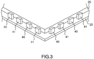
- the figure 3 schematically represents a keyboard 10 in perspective.
- sources for generating the wave propagated in the waveguide 20 are shown.
- the keyboard 10 is flat and extends for example according to a parallelepiped surface.
- the waveguide 20 extends substantially over the entire surface of the keyboard 10.
- the wave sources propagating in the waveguide 20 may be formed of light-emitting diodes disposed around the periphery of the waveguide 20 and the waveguide 20. illuminating by its slice.
- the sources can all be identical and all emit on the same wavelength.
- the sources it is possible to differentiate the sources according to their use. More specifically, it is possible to use different sources of wavelength for the detection of the support by the divers and for the backlighting of the keyboard 10.
- diodes emitting in an infrared band for the detecting the support of the plungers and diodes emitting in a band of visible wavelength for the backlighting The two types of diodes are for example alternated around the waveguide. The proportion of diodes emitting in each of the bands is adapted according to the need. Thus, the risk of interference between the backlight and the detection of the support by the divers is reduced.
- the sensors 26 and 27 are also adapted to detect the wavelength band chosen for the diodes provided for detecting the support of the divers.
- diodes 40 emit in the infrared and diodes 41 emit in a band of visible length.
- the altered zones 37 may comprise a particular treatment to limit the wavelength transmission chosen for the diodes provided for detecting the support of the divers.
- the keyboard comprises a light source 45 controlled by the representative signal from the corresponding sensor.
- This light source 45 is activated according to the support by the user on the corresponding key.
- the feedback can be direct, the light source 45 can be active only in case of support.
- the feedback can be indirect, for example when a single-effect key is used to control a relay.
- the light source 45 is activated when the key activating the relay is pressed for the first time and deactivated during a subsequent press deactivating the relay.
- the light source 45 may be arranged to emit in the waveguide 20. The source is then disposed at the periphery of the waveguide 20 as the sources 40 and 41. Alternatively, the light source 45 is disposed of to emit light perpendicular to the waveguide 20 through it. This alternative is well suited to a keyboard with several keys and for which we want a separate order of return for each of the keys.
- the light source 45 is for example formed of one or more light-emitting diodes arranged on the printed circuit 25 near the sensor corresponding to the key for which feedback is desired. The wall 28 can separate the light source 45 from the corresponding sensor.
- the senor may be insensitive to the light emitted by the source 45.
- the sensor can work in the infrared, the backlight in the red and the feedback in the green. It is possible to provide several different colors for different feedback, for a keyboard 10 to several keys, or for the same key depending on its use.
- a keyboard according to the invention makes it possible to separate the mechanical action on the key from the detection of this mechanical action. Physically this separation is done by the waveguide 20. This physical separation can be used to electromagnetically isolate the keys of the keyboard 10 and the electrical signals deviated by the keyboard as a function of key presses.
- the keyboard 10 comprises an electric shielding screen 50 disposed on one of the faces of the waveguide, the screen of shielding being transparent to the wave (or waves) propagated in the waveguide 20 and optionally transparent to the light used for the return of order.
- the shielding screen is for example made by means of a transparent conductive electrode disposed on one of the faces 22 and 23.
- This electrode is for example made of indium oxide doped with tin well known under the name of ITO for its abbreviation Anglo-Saxon: Indium tin oxide.
- Other technologies can be implemented to achieve the shielding screen 50, such as for example the implementation of a transparent film incorporating a conductive grid. This type of film is known in the Anglo-Saxon literature under the name of "micro mesh film”.
- the shielding screen 50 covers the entire surface of the waveguide 20 and is connected to an electrical ground of the keyboard, for example by means of the printed circuit 25.
Landscapes
- Engineering & Computer Science (AREA)
- General Engineering & Computer Science (AREA)
- Theoretical Computer Science (AREA)
- Human Computer Interaction (AREA)
- Physics & Mathematics (AREA)
- General Physics & Mathematics (AREA)
- Input From Keyboards Or The Like (AREA)
- Push-Button Switches (AREA)
- Switches Operated By Changes In Physical Conditions (AREA)
Applications Claiming Priority (1)
| Application Number | Priority Date | Filing Date | Title |
|---|---|---|---|
| FR1402876A FR3030797B1 (fr) | 2014-12-17 | 2014-12-17 | Clavier a fiabilite amelioree |
Publications (2)
| Publication Number | Publication Date |
|---|---|
| EP3035534A1 true EP3035534A1 (de) | 2016-06-22 |
| EP3035534B1 EP3035534B1 (de) | 2018-04-04 |
Family
ID=53177512
Family Applications (1)
| Application Number | Title | Priority Date | Filing Date |
|---|---|---|---|
| EP15200021.2A Active EP3035534B1 (de) | 2014-12-17 | 2015-12-15 | Tastatur mit verbesserter zuverlässigkeit |
Country Status (4)
| Country | Link |
|---|---|
| US (1) | US9778753B2 (de) |
| EP (1) | EP3035534B1 (de) |
| CA (1) | CA2915340C (de) |
| FR (1) | FR3030797B1 (de) |
Families Citing this family (7)
| Publication number | Priority date | Publication date | Assignee | Title |
|---|---|---|---|---|
| US10037087B2 (en) * | 2015-10-29 | 2018-07-31 | Dell Products L.P. | Low profile information handling system keyboard |
| TW201816817A (zh) * | 2016-10-28 | 2018-05-01 | 致伸科技股份有限公司 | 按鍵結構 |
| US11770123B2 (en) | 2018-01-05 | 2023-09-26 | Darfon Electronics Corp. | Optical keyswitch comprising a keycap having a light transmission area and a keycap projection area projected on a circuit board |
| US11018667B2 (en) | 2018-01-05 | 2021-05-25 | Darfon Electronics Corp. | Optical keyswitch |
| US10637470B2 (en) | 2018-01-05 | 2020-04-28 | Darfon Electronics Corp. | Optical keyswitch |
| US11735379B2 (en) | 2021-04-07 | 2023-08-22 | Darfon Electronics Corp. | Keyswitch assembly |
| US11721500B2 (en) | 2021-04-07 | 2023-08-08 | Darfon Electronics Corp. | Keyswitch assembly and support mechanism thereof |
Citations (11)
| Publication number | Priority date | Publication date | Assignee | Title |
|---|---|---|---|---|
| GB2074428A (en) * | 1980-04-16 | 1981-10-28 | Western Electric Co | Touch sensitive device |
| FR2521330A1 (fr) * | 1982-02-11 | 1983-08-12 | Western Electric Co | Dispositif sensible au toucher |
| US5975711A (en) * | 1995-06-27 | 1999-11-02 | Lumitex, Inc. | Integrated display panel assemblies |
| DE19856008A1 (de) * | 1998-12-04 | 2000-06-21 | Bayer Ag | Berührungssensor |
| US20030052257A1 (en) * | 2001-08-21 | 2003-03-20 | Sarun Sumriddetchkajorn | Optical touch switch structures |
| US20030193421A1 (en) * | 2002-04-12 | 2003-10-16 | Nokia Corporation | Switch arrangement and a switch matrix structure for a keypad |
| US6741189B1 (en) * | 1999-10-06 | 2004-05-25 | Microsoft Corporation | Keypad having optical waveguides |
| JP2004214059A (ja) * | 2003-01-06 | 2004-07-29 | Smk Corp | 操作パネル入力装置 |
| GB2409515A (en) * | 2003-12-24 | 2005-06-29 | Nokia Corp | Analogue navigation device utilising differing refractive indices |
| WO2005125011A1 (en) * | 2004-06-19 | 2005-12-29 | United Kingdom Atomic Energy Authority | An optical touch pad |
| US20100326803A1 (en) * | 2009-06-24 | 2010-12-30 | Keetae Um | Keypad with a light guide pad |
Family Cites Families (5)
| Publication number | Priority date | Publication date | Assignee | Title |
|---|---|---|---|---|
| US7275836B2 (en) * | 2005-08-13 | 2007-10-02 | Palm, Inc. | Lighting and usability features for key structures and keypads on computing devices |
| WO2008102196A1 (en) * | 2007-02-23 | 2008-08-28 | Nokia Corporation | Optical actuators in keypads |
| CN102473037A (zh) * | 2009-08-07 | 2012-05-23 | 株式会社藤仓 | 键盘装置 |
| TW201409512A (zh) * | 2012-08-23 | 2014-03-01 | Hon Hai Prec Ind Co Ltd | 一種按鍵裝置及其導光膜層 |
| TWI459425B (zh) * | 2012-12-19 | 2014-11-01 | Primax Electronics Ltd | 發光鍵盤 |
-
2014
- 2014-12-17 FR FR1402876A patent/FR3030797B1/fr not_active Expired - Fee Related
-
2015
- 2015-12-15 CA CA2915340A patent/CA2915340C/fr active Active
- 2015-12-15 EP EP15200021.2A patent/EP3035534B1/de active Active
- 2015-12-16 US US14/971,966 patent/US9778753B2/en active Active
Patent Citations (11)
| Publication number | Priority date | Publication date | Assignee | Title |
|---|---|---|---|---|
| GB2074428A (en) * | 1980-04-16 | 1981-10-28 | Western Electric Co | Touch sensitive device |
| FR2521330A1 (fr) * | 1982-02-11 | 1983-08-12 | Western Electric Co | Dispositif sensible au toucher |
| US5975711A (en) * | 1995-06-27 | 1999-11-02 | Lumitex, Inc. | Integrated display panel assemblies |
| DE19856008A1 (de) * | 1998-12-04 | 2000-06-21 | Bayer Ag | Berührungssensor |
| US6741189B1 (en) * | 1999-10-06 | 2004-05-25 | Microsoft Corporation | Keypad having optical waveguides |
| US20030052257A1 (en) * | 2001-08-21 | 2003-03-20 | Sarun Sumriddetchkajorn | Optical touch switch structures |
| US20030193421A1 (en) * | 2002-04-12 | 2003-10-16 | Nokia Corporation | Switch arrangement and a switch matrix structure for a keypad |
| JP2004214059A (ja) * | 2003-01-06 | 2004-07-29 | Smk Corp | 操作パネル入力装置 |
| GB2409515A (en) * | 2003-12-24 | 2005-06-29 | Nokia Corp | Analogue navigation device utilising differing refractive indices |
| WO2005125011A1 (en) * | 2004-06-19 | 2005-12-29 | United Kingdom Atomic Energy Authority | An optical touch pad |
| US20100326803A1 (en) * | 2009-06-24 | 2010-12-30 | Keetae Um | Keypad with a light guide pad |
Also Published As
| Publication number | Publication date |
|---|---|
| CA2915340A1 (fr) | 2016-06-17 |
| FR3030797A1 (fr) | 2016-06-24 |
| US9778753B2 (en) | 2017-10-03 |
| EP3035534B1 (de) | 2018-04-04 |
| US20160179212A1 (en) | 2016-06-23 |
| FR3030797B1 (fr) | 2018-05-11 |
| CA2915340C (fr) | 2022-08-30 |
Similar Documents
| Publication | Publication Date | Title |
|---|---|---|
| EP3035534B1 (de) | Tastatur mit verbesserter zuverlässigkeit | |
| US11699558B2 (en) | Keycaps having reduced thickness | |
| EP2045923B1 (de) | Vorrichtung mit beleuchteter, auf dem kapazitiven Effekt beruhenden berührungsempfindlichen Taste und Steuertastatur, die eine solche Vorrichtung umfasst | |
| CN105678255B (zh) | 一种光学式指纹识别显示屏及显示装置 | |
| KR102436320B1 (ko) | 근조도 센서 및 이를 포함하는 휴대용 단말기 | |
| FR2697935A1 (fr) | Terminal de communication compact et ergonomique muni de surfaces de détection de proximité. | |
| US20110272262A1 (en) | Luminous keyboard | |
| EP4495681A3 (de) | Lichtemittierende vorrichtung | |
| JP5020050B2 (ja) | 操作スイッチ用カバー部材 | |
| CN102621613B (zh) | 光组件以及光分析装置 | |
| US20110031380A1 (en) | Optical pointing device | |
| CN104678474A (zh) | 电子器件以及电子设备 | |
| US20090059378A1 (en) | Devices, Systems, and/or Methods for Providing Illumination | |
| CA2915339C (fr) | Codeur optique robuste | |
| JP2018006228A (ja) | 操作表示装置 | |
| KR102024862B1 (ko) | 표시 장치 | |
| CN104850839A (zh) | 光学采集模组的光控制组件及成型方法 | |
| US20130114296A1 (en) | Light guide apparatus and electronic device using the same | |
| JP7656511B2 (ja) | 押しボタンスイッチ | |
| KR101140991B1 (ko) | 레이져 네비게이션 모듈 | |
| JP2016081587A (ja) | 可動接点体及びこれを用いたスイッチ | |
| KR101148670B1 (ko) | 레이져 네비게이션 모듈 | |
| US20200365349A1 (en) | Keyboard | |
| FR2906947A1 (fr) | Dispositif a touche sensitive par effet capacitif retro eclaire et clavier de commande comprenant un tel dispositif. | |
| JP2003242814A (ja) | 照明装置及び液晶表示装置 |
Legal Events
| Date | Code | Title | Description |
|---|---|---|---|
| PUAI | Public reference made under article 153(3) epc to a published international application that has entered the european phase |
Free format text: ORIGINAL CODE: 0009012 |
|
| AK | Designated contracting states |
Kind code of ref document: A1 Designated state(s): AL AT BE BG CH CY CZ DE DK EE ES FI FR GB GR HR HU IE IS IT LI LT LU LV MC MK MT NL NO PL PT RO RS SE SI SK SM TR |
|
| AX | Request for extension of the european patent |
Extension state: BA ME |
|
| 17P | Request for examination filed |
Effective date: 20161215 |
|
| RBV | Designated contracting states (corrected) |
Designated state(s): AL AT BE BG CH CY CZ DE DK EE ES FI FR GB GR HR HU IE IS IT LI LT LU LV MC MK MT NL NO PL PT RO RS SE SI SK SM TR |
|
| GRAP | Despatch of communication of intention to grant a patent |
Free format text: ORIGINAL CODE: EPIDOSNIGR1 |
|
| INTG | Intention to grant announced |
Effective date: 20171027 |
|
| GRAS | Grant fee paid |
Free format text: ORIGINAL CODE: EPIDOSNIGR3 |
|
| GRAA | (expected) grant |
Free format text: ORIGINAL CODE: 0009210 |
|
| AK | Designated contracting states |
Kind code of ref document: B1 Designated state(s): AL AT BE BG CH CY CZ DE DK EE ES FI FR GB GR HR HU IE IS IT LI LT LU LV MC MK MT NL NO PL PT RO RS SE SI SK SM TR |
|
| REG | Reference to a national code |
Ref country code: GB Ref legal event code: FG4D Free format text: NOT ENGLISH |
|
| REG | Reference to a national code |
Ref country code: CH Ref legal event code: EP |
|
| REG | Reference to a national code |
Ref country code: AT Ref legal event code: REF Ref document number: 986633 Country of ref document: AT Kind code of ref document: T Effective date: 20180415 |
|
| REG | Reference to a national code |
Ref country code: IE Ref legal event code: FG4D Free format text: LANGUAGE OF EP DOCUMENT: FRENCH |
|
| REG | Reference to a national code |
Ref country code: DE Ref legal event code: R096 Ref document number: 602015009515 Country of ref document: DE |
|
| REG | Reference to a national code |
Ref country code: NL Ref legal event code: MP Effective date: 20180404 |
|
| REG | Reference to a national code |
Ref country code: LT Ref legal event code: MG4D |
|
| PG25 | Lapsed in a contracting state [announced via postgrant information from national office to epo] |
Ref country code: NL Free format text: LAPSE BECAUSE OF FAILURE TO SUBMIT A TRANSLATION OF THE DESCRIPTION OR TO PAY THE FEE WITHIN THE PRESCRIBED TIME-LIMIT Effective date: 20180404 |
|
| PG25 | Lapsed in a contracting state [announced via postgrant information from national office to epo] |
Ref country code: ES Free format text: LAPSE BECAUSE OF FAILURE TO SUBMIT A TRANSLATION OF THE DESCRIPTION OR TO PAY THE FEE WITHIN THE PRESCRIBED TIME-LIMIT Effective date: 20180404 Ref country code: SE Free format text: LAPSE BECAUSE OF FAILURE TO SUBMIT A TRANSLATION OF THE DESCRIPTION OR TO PAY THE FEE WITHIN THE PRESCRIBED TIME-LIMIT Effective date: 20180404 Ref country code: AL Free format text: LAPSE BECAUSE OF FAILURE TO SUBMIT A TRANSLATION OF THE DESCRIPTION OR TO PAY THE FEE WITHIN THE PRESCRIBED TIME-LIMIT Effective date: 20180404 Ref country code: FI Free format text: LAPSE BECAUSE OF FAILURE TO SUBMIT A TRANSLATION OF THE DESCRIPTION OR TO PAY THE FEE WITHIN THE PRESCRIBED TIME-LIMIT Effective date: 20180404 Ref country code: BG Free format text: LAPSE BECAUSE OF FAILURE TO SUBMIT A TRANSLATION OF THE DESCRIPTION OR TO PAY THE FEE WITHIN THE PRESCRIBED TIME-LIMIT Effective date: 20180704 Ref country code: NO Free format text: LAPSE BECAUSE OF FAILURE TO SUBMIT A TRANSLATION OF THE DESCRIPTION OR TO PAY THE FEE WITHIN THE PRESCRIBED TIME-LIMIT Effective date: 20180704 Ref country code: PL Free format text: LAPSE BECAUSE OF FAILURE TO SUBMIT A TRANSLATION OF THE DESCRIPTION OR TO PAY THE FEE WITHIN THE PRESCRIBED TIME-LIMIT Effective date: 20180404 Ref country code: LT Free format text: LAPSE BECAUSE OF FAILURE TO SUBMIT A TRANSLATION OF THE DESCRIPTION OR TO PAY THE FEE WITHIN THE PRESCRIBED TIME-LIMIT Effective date: 20180404 |
|
| PG25 | Lapsed in a contracting state [announced via postgrant information from national office to epo] |
Ref country code: HR Free format text: LAPSE BECAUSE OF FAILURE TO SUBMIT A TRANSLATION OF THE DESCRIPTION OR TO PAY THE FEE WITHIN THE PRESCRIBED TIME-LIMIT Effective date: 20180404 Ref country code: GR Free format text: LAPSE BECAUSE OF FAILURE TO SUBMIT A TRANSLATION OF THE DESCRIPTION OR TO PAY THE FEE WITHIN THE PRESCRIBED TIME-LIMIT Effective date: 20180705 Ref country code: LV Free format text: LAPSE BECAUSE OF FAILURE TO SUBMIT A TRANSLATION OF THE DESCRIPTION OR TO PAY THE FEE WITHIN THE PRESCRIBED TIME-LIMIT Effective date: 20180404 Ref country code: RS Free format text: LAPSE BECAUSE OF FAILURE TO SUBMIT A TRANSLATION OF THE DESCRIPTION OR TO PAY THE FEE WITHIN THE PRESCRIBED TIME-LIMIT Effective date: 20180404 |
|
| REG | Reference to a national code |
Ref country code: AT Ref legal event code: MK05 Ref document number: 986633 Country of ref document: AT Kind code of ref document: T Effective date: 20180404 |
|
| PG25 | Lapsed in a contracting state [announced via postgrant information from national office to epo] |
Ref country code: PT Free format text: LAPSE BECAUSE OF FAILURE TO SUBMIT A TRANSLATION OF THE DESCRIPTION OR TO PAY THE FEE WITHIN THE PRESCRIBED TIME-LIMIT Effective date: 20180806 |
|
| REG | Reference to a national code |
Ref country code: DE Ref legal event code: R097 Ref document number: 602015009515 Country of ref document: DE |
|
| PG25 | Lapsed in a contracting state [announced via postgrant information from national office to epo] |
Ref country code: CZ Free format text: LAPSE BECAUSE OF FAILURE TO SUBMIT A TRANSLATION OF THE DESCRIPTION OR TO PAY THE FEE WITHIN THE PRESCRIBED TIME-LIMIT Effective date: 20180404 Ref country code: RO Free format text: LAPSE BECAUSE OF FAILURE TO SUBMIT A TRANSLATION OF THE DESCRIPTION OR TO PAY THE FEE WITHIN THE PRESCRIBED TIME-LIMIT Effective date: 20180404 Ref country code: EE Free format text: LAPSE BECAUSE OF FAILURE TO SUBMIT A TRANSLATION OF THE DESCRIPTION OR TO PAY THE FEE WITHIN THE PRESCRIBED TIME-LIMIT Effective date: 20180404 Ref country code: AT Free format text: LAPSE BECAUSE OF FAILURE TO SUBMIT A TRANSLATION OF THE DESCRIPTION OR TO PAY THE FEE WITHIN THE PRESCRIBED TIME-LIMIT Effective date: 20180404 Ref country code: SK Free format text: LAPSE BECAUSE OF FAILURE TO SUBMIT A TRANSLATION OF THE DESCRIPTION OR TO PAY THE FEE WITHIN THE PRESCRIBED TIME-LIMIT Effective date: 20180404 Ref country code: DK Free format text: LAPSE BECAUSE OF FAILURE TO SUBMIT A TRANSLATION OF THE DESCRIPTION OR TO PAY THE FEE WITHIN THE PRESCRIBED TIME-LIMIT Effective date: 20180404 |
|
| PLBE | No opposition filed within time limit |
Free format text: ORIGINAL CODE: 0009261 |
|
| STAA | Information on the status of an ep patent application or granted ep patent |
Free format text: STATUS: NO OPPOSITION FILED WITHIN TIME LIMIT |
|
| PG25 | Lapsed in a contracting state [announced via postgrant information from national office to epo] |
Ref country code: SM Free format text: LAPSE BECAUSE OF FAILURE TO SUBMIT A TRANSLATION OF THE DESCRIPTION OR TO PAY THE FEE WITHIN THE PRESCRIBED TIME-LIMIT Effective date: 20180404 |
|
| 26N | No opposition filed |
Effective date: 20190107 |
|
| PG25 | Lapsed in a contracting state [announced via postgrant information from national office to epo] |
Ref country code: SI Free format text: LAPSE BECAUSE OF FAILURE TO SUBMIT A TRANSLATION OF THE DESCRIPTION OR TO PAY THE FEE WITHIN THE PRESCRIBED TIME-LIMIT Effective date: 20180404 |
|
| REG | Reference to a national code |
Ref country code: CH Ref legal event code: PL |
|
| PG25 | Lapsed in a contracting state [announced via postgrant information from national office to epo] |
Ref country code: LU Free format text: LAPSE BECAUSE OF NON-PAYMENT OF DUE FEES Effective date: 20181215 Ref country code: MC Free format text: LAPSE BECAUSE OF FAILURE TO SUBMIT A TRANSLATION OF THE DESCRIPTION OR TO PAY THE FEE WITHIN THE PRESCRIBED TIME-LIMIT Effective date: 20180404 |
|
| REG | Reference to a national code |
Ref country code: IE Ref legal event code: MM4A |
|
| PG25 | Lapsed in a contracting state [announced via postgrant information from national office to epo] |
Ref country code: IE Free format text: LAPSE BECAUSE OF NON-PAYMENT OF DUE FEES Effective date: 20181215 |
|
| PG25 | Lapsed in a contracting state [announced via postgrant information from national office to epo] |
Ref country code: CH Free format text: LAPSE BECAUSE OF NON-PAYMENT OF DUE FEES Effective date: 20181231 Ref country code: LI Free format text: LAPSE BECAUSE OF NON-PAYMENT OF DUE FEES Effective date: 20181231 |
|
| PG25 | Lapsed in a contracting state [announced via postgrant information from national office to epo] |
Ref country code: MT Free format text: LAPSE BECAUSE OF FAILURE TO SUBMIT A TRANSLATION OF THE DESCRIPTION OR TO PAY THE FEE WITHIN THE PRESCRIBED TIME-LIMIT Effective date: 20180404 |
|
| PG25 | Lapsed in a contracting state [announced via postgrant information from national office to epo] |
Ref country code: TR Free format text: LAPSE BECAUSE OF FAILURE TO SUBMIT A TRANSLATION OF THE DESCRIPTION OR TO PAY THE FEE WITHIN THE PRESCRIBED TIME-LIMIT Effective date: 20180404 |
|
| PG25 | Lapsed in a contracting state [announced via postgrant information from national office to epo] |
Ref country code: HU Free format text: LAPSE BECAUSE OF FAILURE TO SUBMIT A TRANSLATION OF THE DESCRIPTION OR TO PAY THE FEE WITHIN THE PRESCRIBED TIME-LIMIT; INVALID AB INITIO Effective date: 20151215 Ref country code: MK Free format text: LAPSE BECAUSE OF NON-PAYMENT OF DUE FEES Effective date: 20180404 Ref country code: CY Free format text: LAPSE BECAUSE OF FAILURE TO SUBMIT A TRANSLATION OF THE DESCRIPTION OR TO PAY THE FEE WITHIN THE PRESCRIBED TIME-LIMIT Effective date: 20180404 |
|
| PG25 | Lapsed in a contracting state [announced via postgrant information from national office to epo] |
Ref country code: IS Free format text: LAPSE BECAUSE OF FAILURE TO SUBMIT A TRANSLATION OF THE DESCRIPTION OR TO PAY THE FEE WITHIN THE PRESCRIBED TIME-LIMIT Effective date: 20180804 |
|
| GBPC | Gb: european patent ceased through non-payment of renewal fee |
Effective date: 20191215 |
|
| PG25 | Lapsed in a contracting state [announced via postgrant information from national office to epo] |
Ref country code: GB Free format text: LAPSE BECAUSE OF NON-PAYMENT OF DUE FEES Effective date: 20191215 |
|
| P01 | Opt-out of the competence of the unified patent court (upc) registered |
Effective date: 20230427 |
|
| PGFP | Annual fee paid to national office [announced via postgrant information from national office to epo] |
Ref country code: IT Payment date: 20231128 Year of fee payment: 9 |
|
| PG25 | Lapsed in a contracting state [announced via postgrant information from national office to epo] |
Ref country code: IT Free format text: LAPSE BECAUSE OF NON-PAYMENT OF DUE FEES Effective date: 20241215 |
|
| PGFP | Annual fee paid to national office [announced via postgrant information from national office to epo] |
Ref country code: DE Payment date: 20251119 Year of fee payment: 11 |
|
| PGFP | Annual fee paid to national office [announced via postgrant information from national office to epo] |
Ref country code: FR Payment date: 20251124 Year of fee payment: 11 |
|
| PGFP | Annual fee paid to national office [announced via postgrant information from national office to epo] |
Ref country code: BE Payment date: 20251117 Year of fee payment: 11 |