EP3035623B1 - Prétraitement pour un émetteur optique basé sur une transformée de Fourier non linéaire - Google Patents
Prétraitement pour un émetteur optique basé sur une transformée de Fourier non linéaire Download PDFInfo
- Publication number
- EP3035623B1 EP3035623B1 EP14307102.5A EP14307102A EP3035623B1 EP 3035623 B1 EP3035623 B1 EP 3035623B1 EP 14307102 A EP14307102 A EP 14307102A EP 3035623 B1 EP3035623 B1 EP 3035623B1
- Authority
- EP
- European Patent Office
- Prior art keywords
- signal
- complex
- domain signal
- time domain
- complex frequency
- Prior art date
- Legal status (The legal status is an assumption and is not a legal conclusion. Google has not performed a legal analysis and makes no representation as to the accuracy of the status listed.)
- Active
Links
Images



Classifications
-
- H—ELECTRICITY
- H04—ELECTRIC COMMUNICATION TECHNIQUE
- H04L—TRANSMISSION OF DIGITAL INFORMATION, e.g. TELEGRAPHIC COMMUNICATION
- H04L27/00—Modulated-carrier systems
- H04L27/26—Systems using multi-frequency codes
- H04L27/2601—Multicarrier modulation systems
- H04L27/2697—Multicarrier modulation systems in combination with other modulation techniques
-
- H—ELECTRICITY
- H04—ELECTRIC COMMUNICATION TECHNIQUE
- H04B—TRANSMISSION
- H04B10/00—Transmission systems employing electromagnetic waves other than radio-waves, e.g. infrared, visible or ultraviolet light, or employing corpuscular radiation, e.g. quantum communication
- H04B10/25—Arrangements specific to fibre transmission
- H04B10/2507—Arrangements specific to fibre transmission for the reduction or elimination of distortion or dispersion
- H04B10/2543—Arrangements specific to fibre transmission for the reduction or elimination of distortion or dispersion due to fibre non-linearities, e.g. Kerr effect
-
- H—ELECTRICITY
- H04—ELECTRIC COMMUNICATION TECHNIQUE
- H04B—TRANSMISSION
- H04B10/00—Transmission systems employing electromagnetic waves other than radio-waves, e.g. infrared, visible or ultraviolet light, or employing corpuscular radiation, e.g. quantum communication
- H04B10/50—Transmitters
- H04B10/516—Details of coding or modulation
- H04B10/548—Phase or frequency modulation
-
- H—ELECTRICITY
- H04—ELECTRIC COMMUNICATION TECHNIQUE
- H04L—TRANSMISSION OF DIGITAL INFORMATION, e.g. TELEGRAPHIC COMMUNICATION
- H04L27/00—Modulated-carrier systems
- H04L27/26—Systems using multi-frequency codes
- H04L27/2601—Multicarrier modulation systems
- H04L27/2626—Arrangements specific to the transmitter only
- H04L27/2627—Modulators
- H04L27/2634—Inverse fast Fourier transform [IFFT] or inverse discrete Fourier transform [IDFT] modulators in combination with other circuits for modulation
- H04L27/2636—Inverse fast Fourier transform [IFFT] or inverse discrete Fourier transform [IDFT] modulators in combination with other circuits for modulation with FFT or DFT modulators, e.g. standard single-carrier frequency-division multiple access [SC-FDMA] transmitter or DFT spread orthogonal frequency division multiplexing [DFT-SOFDM]
Definitions
- Embodiments described in the following relate to signal transformation circuitries, methods and computer programs for a signal transformation circuitry, preferrably to signal transformation circuitries comprised by an optical communication system with an optical communication channel.
- Fibers are widely used in fiber-optic communications, where they may permit transmission over longer distances and at higher bandwidths or data rates than wire cables.
- Fibers are used for a variety of applications, including sensors and fiber lasers. They are in some cases used instead of metal wires because signals may travel along them with less loss and are also less prone to some error sources, for example electromagnetic interference.
- An increase of the optical power which should allow the transportation of more information bits in a given spectral range introduces nonlinear distortion. Fiber nonlinearities may arise from several mechanisms.
- Fiber nonlinearities may impose a fundamental limit to the amount of data that can be transmitted on a single optic fiber. On a receiver side these nonlinearities may lead to complex digital signal processing (DSP) steps that may be required to retrieve an originally transmitted signal from a received signal.
- DSP digital signal processing
- NFT nonlinear Fourier transform
- inventions provide a signal transformation circuitry.
- the signal transformation circuitry comprises a first transform module configured to transform a time domain signal to a complex frequency domain signal.
- the signal transformation circuitry further comprises a second transform module configured to perform an inverse transformation based on a non-zero imaginary part of the complex frequency domain signal to obtain a modified time domain signal.
- a better use of existing signal power e.g. in optical applications, may thus be achieved.
- this may enable a possibility for signal preprocessing, e.g. for a transmitter, that may lessen distortion effects during transmission and hence simplify signal detection on a receiver side.
- the complex frequency domain signal comprises one or more complex frequencies.
- the second transform module is further configured to perform the inverse transformation based on one or more complex frequencies in the upper or lower complex half-plane.
- the first transform module is further configured to obtain the one or more complex frequencies in the upper or lower complex half-plane from the transformation of the time domain signal.
- the second transform module is configured to perform the inverse transformation if an imaginary part of the one or more complex frequencies is outside a predetermined interval comprising zero.
- the second transform module is further configured to set a value of the complex frequency domain signal to zero if a complex frequency assigned to the value of the complex frequency domain signal is a real number value.
- the second transform module is further configured to perform the inverse transformation using a complex frequency with a non-zero imaginary part and a value of the complex frequency domain signal if the value is assigned to the complex frequency or equal zero.
- the first transform module is further configured to transform the time domain signal to the complex frequency domain signal using a nonlinear signal transformation.
- the first transform module is further configured to transform the time domain signal to the complex frequency domain signal using a nonlinear Fourier transform.
- the second transform module is further configured to perform the inverse transformation as an inverse nonlinear Fourier transform.
- the second transform module is further configured to perform the inverse nonlinear Fourier transform corresponding to a Darboux transform.
- the complex frequency domain signal exhibits at least a local maximum or pole assigned to a complex frequency with an imaginary part larger than zero.
- the second transform module is configured to obtain the modified time domain signal from the transformation as an optical signal.
- the at least one local maximum or pole therein corresponds to at least one soliton of the modified time domain signal.
- the second transform module is configured to obtain the modified time domain signal from the transformation as an optical signal. Therein, at least 50 per cent of a signal power of the modified time domain signal is caused by one or more solitons of the modified time domain signal.
- the second transform module is configured to obtain the modified time domain signal from the transformation as an optical signal. Therein, less than 5 per cent of a signal power of the modified time domain signal is caused by a fraction of the complex frequency domain signal assigned to a complex frequency with an imaginary part equal to zero.
- the transmitter comprises said signal transformation circuitry and a transmission interface configured to provide the modified time domain signal as a transmit signal.
- the transmission interface is coupled to an optical transmission channel.
- the transmit signal therein is an optical signal.
- a method for a signal transformation circuitry comprises a transforming of a time domain transmit signal to a complex frequency domain transmit signal.
- the method further comprises a performing of an inverse transformation based on a non-zero imaginary part of the complex frequency domain signal to obtain a modified time domain signal.
- Some embodiments comprise a computer readable storage medium storing instructions which, when executed by a computer, cause the computer to implement the method described herein, or a digital control circuit installed within the apparatus for performing the method.
- a digital control circuit e.g. a digital signal processor (DSP)
- DSP digital signal processor
- yet further embodiments also provide a computer program having a program code for performing embodiments of the method, when the computer program is executed on a computer or a digital processor.
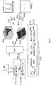
- Fig. 1 provides an overview of mathematical operations comprised by a nonlinear Fourier transform (NFT) according to a conventional solution.
- E(t') is a coherently detected optical signal, wherein t' is a time-related variable. Due to the abovementioned effects of nonlinearity the detected signal undergoes distortion, which is resolved by transforming into the nonlinear frequency domain.
- This transformation comprises different steps. First the time t' is transformed to a modified temporal variable t via equation (1-1), and signal E(t') to a modified signal Q(t) via eq. (1-2).
- ⁇ 2,NL denotes a dispersion coefficient of an ideal fiber channel, ⁇ NL a nonlinear coefficient of the fiber channel, L NL a length of the fiber channel, and P NL a mean signal power.
- the NFT is performed according to an iterative principle with k running from 0 to N which is described in eq. (1-3) and is known as the Ablowitz-Ladik method.
- a signal vector (v 1 , v 2 ) for iteration step k+1 may be obtained from a preceding signal vector (v 1 , v 2 ) for iteration step k.
- the logarithms of a( ⁇ ) and b( ⁇ ) are shown as three-dimensional contour plots in the center of Fig.1 . Inserting a( ⁇ ) and b( ⁇ ) in eq. (1-6) leads to the amplitudes q( ⁇ ) of the continuous spectrum for continuous frequencies ⁇ along the real axis of the complex plane and q( ⁇ i ) at the discrete frequency points.
- SSMF standard single mode fiber
- the NFT requires the channel parameter ⁇ 2,NL and ⁇ NL in addition.
- the complex spectral amplitude q( ⁇ ) at a frequency point ⁇ is determined in three computational steps.
- the discrete frequency points may be found by applying a search on zeros of
- a ′ k ⁇ j ⁇ ⁇ t ⁇ exp ⁇ j ⁇ ⁇ t 0 0 j ⁇ ⁇ ⁇ t ⁇ exp j ⁇ ⁇ t already described above.
- a first part is a continuous part which is the amplitude q c ( ⁇ ) over the nonlinear frequency ⁇ (see upper right drawing in Fig.1 ), and can be obtained from eq. (1-6).
- the continuous part corresponds to a real part of the frequency spectrum.
- a second part is a discrete part of the spectrum which are isolated nonlinear frequency points ⁇ j in the upper complex plane (see lower right drawing in Fig.1 ) with the amplitude q d ( ⁇ j ).
- the frequency points ⁇ j are often referred to as eigenvalues.
- the frequency points may be found by a zero search of the spectral coefficient a( ⁇ ) for ⁇ in the complex plane.
- the corresponding amplitude q d ( ⁇ j ) may be obtained from eq. (1-7) using the derivative of a( ⁇ ) by frequency ⁇ according to the aforementioned calculation rules.
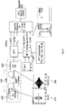
- Fig. 2 schematically displays a signal detection scheme as is conventionally done in a maximum likelihood nonlinear detection process.
- a transmitter 205 sends a transmit signal 210 (E(t,0)) through an optical fiber 215, which in an example has a length between 80 and 240 km. Transmit signal 210 undergoes notable distortion while passing fiber 215, and is received as a receive signal 220 (Re(E(t,L))) by a receiver 225.
- Receive signal 220 is transformed with the NFT described in Fig. 1 .
- the NFT in both cases uses the optical fiber parameters ⁇ 2,NL , ⁇ NL , L NL , and P NL .
- the continuous frequency domain signal q c ( ⁇ ), the discrete frequency domain signal q d ( ⁇ j ), and discrete frequency point ⁇ j as well as a multitude of hypothetical continuous frequency domain signals q c,ref-i ( ⁇ ), hypothetical discrete frequency domain signals q d,ref-i ( ⁇ j,ref-i ), and discrete frequency point ⁇ j,refi can be obtained.
- the received continuous spectrum and frequency point are compared with each hypothetical continuous spectrum and frequency point, which results in a differential value called the spectral distance D. From the multitude of results for D, with each result corresponding to a distinct hypothetical signal, the minimum value of all D decides which hypothetical signal is most likely corresponding to the original transmit signal 210.
- ML-NS maximum likelihood nonlinear spectrum
- the mean difference of the continuous spectrum ⁇ (q c -q c,ref-i ) 2 > is minimum or of the discrete frequency points ⁇ j ( ⁇ j - ⁇ j,ref-i ) 2 is minimum or of the discrete amplitudes ⁇ (q d ( ⁇ j )-q d,ref-i ( ⁇ j,ref-i )) 2 > at these discrete frequency points ( ⁇ j,ref-i ) is minimum or a combination of two or three of these three mean differences is minimum.
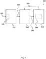
- Fig. 3 shows an exemplary embodiment of a receiver 300.
- Receiver 300 comprises a transform module 310 configured to transform a received time domain signal 320 to a spectral receive signal 330.
- Receiver 300 further comprises a detection module 340 configured to detect a transmit signal based on a comparison of the spectral receive signal 330 with at least one of a plurality of hypothetical spectral receive signals.
- a hypothetical spectral receive signal, or each hypothetical spectral receive signal corresponds to a respective hypothetical transmit signal.
- Receiver 300 also comprises an update module 350 configured to update a hypothetical spectral receive signal of the plurality based on at least one previous spectral receive signal 360 that led to a detection of the transmit signal corresponding to the hypothetical spectral receive signal.
- Received time-domain signal 320 may comprise a real- or complex-valued amplitude plotted against time. Transformation may convert time domain signals into frequency domain.
- spectral receive signal 330 (or also previous spectral receive signal 360) may be a complex frequency domain signal comprising a real- or complex-valued amplitude plotted against complex-valued frequency. That is to say, complex frequency domain signal may comprise one or more couples of values, each couple formed by a complex frequency and a real- or complex-valued amplitude assigned to each other.
- Receiver 300 may be coupled to an optical transmission channel, e.g. an optical fiber, and hence received time domain signal 320 may be an optical signal. In other embodiments, received time domain signal 320 may also be an electronic signal, and receiver 300 may comprise for example an interface for a wire-bound connection or an antenna. Transform module 310, detection module 340 and update module 350 may in a different embodiment be implemented as a common physical unit, for instance a microprocessor or any other programmable hardware component, or also comprise one another. Receiver 300 may further exhibit a reception interface 390 to receive time domain signal 320. Received time domain signal 320 may correspond to signal E(t') as explained in Fig. 1 .
- a better agreement between a signal hypothesis and a signal actually received by the receiver may possibly be accomplished. That is, information related to distortion effects affecting previous transmissions may be memorized and taken into account in future evaluation of the actually received signal. This may lead to higher exactness in receiver-sided signal detection.
- received time domain signal 320 is transformed to spectral receive signal 330 using a nonlinear Fourier transform.
- Spectral receive signal 330 may be described in frequency-domain, and comprise a real-valued frequency domain signal q c ( ⁇ ) (in the following denominated as a continuous frequency domain signal), a complex-valued discrete frequency domain signal q d ( ⁇ j ) (in the following denominated as a discrete frequency domain signal), and a complex-valued (also denominated discrete) frequency point ⁇ j .
- These frequency points ⁇ j may resemble eigenvalues related to the transformation.
- the frequency points ⁇ j may indicate a soliton, e.g. propagating through an optical fiber.
- a soliton may be a wave, a wave packet or a pulse that maintains its shape while it travels at constant speed.
- Solitons may be caused by a cancellation of nonlinear and dispersive effects in a medium.
- a hypothetical spectral receive signal may correspond to or comprise one or more of the reference signals q c,ref-i ( ⁇ ), q d,ref-j ( ⁇ j ), and ⁇ j,ref-i (compare Fig. 2 ).
- Spectral receive signal 330 may be compared to a multitude of such reference signals, and a decision may be made by detection module 340, for example by finding a minimum Euclidean distance between a specific reference signal value ⁇ j,ref-i and a value ⁇ j related to spectral receive signal 330.
- the Euclidean distance may be a calculable number value for a spatial distance in complex space.
- Spectral receive signal 330 may be identified as a transmit signal corresponding to the reference signal exhibiting the minimum Euclidean distance to value ⁇ j . Such a decision may have been made previously, and the respective reference signal may be resembled by (previous) spectral receive signal 360 that led to a detection of the transmit signal corresponding to the hypothetical spectral receive signal.
- Previous spectral receive signal 360 may be available to update module 350 for further use.
- receiver 300 may comprise a storage module 380 to store an information related to previous spectral receive signal 360.
- Storage module 380 may optionally be comprised by update module 350, as is shown in Fig.3 .
- Previous spectral receive signal 360 may be used to update the corresponding reference signal or hypothetical spectral receive signal, and an updated hypothetical spectral receive signal 370 may result.
- updated hypothetical spectral receive signal 370 may be provided to detection module 340 by update module 350.
- the discrete part of the reference spectra i.e. amplitudes q d,ref-i and discrete frequency points ⁇ j,ref-i , may be calculated by multiplication of the transmitter spectra with an all pass filter H.
- a decision directed adaptation of the complex frequencies ⁇ j,ref-i and of the amplitudes (phase and magnitude) q d,ref,i ( ⁇ j,ref-i ) is applied.
- spectral receive signal 330 comprises one or more complex frequencies ⁇ j .
- Update module 350 is further configured to update a portion of the hypothetical spectral receive signal corresponding to one or more complex frequencies ⁇ j,ref-i in the upper or lower complex half-plane based on at least one portion of previous spectral receive signal 360 corresponding to one or more complex frequencies in the upper or lower complex half-plane that led to a detection of the transmit signal corresponding to the hypothetical spectral receive signal.
- the complex frequencies ⁇ j of spectral receive signal 330 and ⁇ j,ref-i of the hypothetical spectral receive signal may be used for a comparison.
- the complex frequency ⁇ j,ref-i may be updated using another complex frequency ⁇ j i,ref-i of previous spectral receive signal 360
- update module 350 is configured to update a portion of the hypothetical spectral receive signal corresponding to one or more complex frequencies ⁇ i,ref in the upper or lower complex half-plane based on a mean value of at least two previous spectral receive signal portions corresponding to one or more complex frequencies ⁇ j,ref-i (j may be an index number to differentiate between different complex frequencies) in the upper or lower complex half-plane that led to a detection of the transmit signal corresponding to the hypothetical spectral receive signal. In other words, there may have been a number of N decisions in the past that led to an identification of received time domain signal 320 as a signal corresponding to one specific hypothesis.
- ⁇ j and q d ( ⁇ j )) is an element of a set of N passed received spectra which were decided as i. The average over these received discrete spectra is used as update of the reference spectrum ⁇ j,ref-i and q d,ref-i ( ⁇ j ) which will be used for future decisions.
- It may further be possible in a further embodiment to update the signal hypotheses i 1...16 of the continuous spectra, e.g. q c,ref-i ( ⁇ ) using a mean value of a number of N passed received spectra.
- Embodiments may thus introduce an approach involving decision directed training for the discrete frequency points ⁇ j . These points may however not be viewed or treated as constellation points in some exemplary embodiments.
- a transmitted signal burst (or, correspondingly, spectral receive signal 330) may exhibit more than one point at a time, as is e.g. visualized by the two points in the complex planes in Fig.2 (bottom right panel).
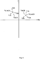
- Fig. 4 visualizes an exemplary process for an update of a hypothetical receive signal exhibiting two complex frequency points in a complex coordinate system, which are labeled ⁇ ref,A and ⁇ ref,B herein.
- a first set of complex frequency points ⁇ 1A , ⁇ 1B of a first spectral receive signal, a second set of complex frequency points ⁇ 2A , ⁇ 2B of a second spectral receive signal and a third set of complex frequency points ⁇ 3A , ⁇ 3B of a third spectral receive signal have been calculated previously from their respective received time domain signals.
- points ⁇ 1A , ⁇ 2A and ⁇ 3A have been assigned to the reference signal complex frequency point ⁇ ref,A
- points ⁇ 1B , ⁇ 2B and ⁇ 3B have been assigned to the reference signal complex frequency point ⁇ ref,B for signal detection.
- the mean value of ⁇ 1A , ⁇ 2A and ⁇ 3A is calculated, resulting in an updated reference signal complex frequency point ⁇ U,ref,A , which may replace complex frequency point ⁇ ref,A , in a future signal detection process, and likewise an updated reference signal complex frequency point ⁇ U,ref,B , which may replace complex frequency point ⁇ ref,B .
- the detection module is configured to detect the transmit signal as the respective hypothetical transmit signal based on an Euclidean distance between the spectral receive signal and an updated hypothetical spectral receive signal corresponding to the respective hypothetical transmit signal.
- the detection module is further configured to detect the transmit signal as a first hypothetical transmit receive signal if an Euclidean distance between the spectral receive signal (e.g. ⁇ 1A ) and the first hypothetical spectral receive signal (e.g. ⁇ ref,A ) corresponding to first hypothetical transmit receive signal is smaller than an Euclidean distance between the spectral receive signal and a second hypothetical spectral receive signal.
- a first and a second updated hypothetical spectral receive signal (e.g. ⁇ U,ref,A ) may be used for the comparison of Euclidean distance.
- the spectral receive signal may, however, comprise a number of complex frequency points which differs from a number of complex frequency points of the reference signal.
- the spectral receive signal may comprise three complex frequency points, whereas the reference signal may comprise four.
- the decision may comprise one or more additional rules. These rules may for example introduce a factor for a calculation related to signal agreement, the factor being based on a number value of the difference in complex frequency points, or even exclude reference signals with a differing number of complex frequency points.
- the update module is configured to receive at least one previous spectral receive signal portion corresponding to one or more complex frequencies in the upper or lower complex half-plane that led to a detection of the transmit signal corresponding to the hypothetical spectral receive signal.
- the previous spectral receive signal portion comprises a previously updated hypothetical spectral receive signal.
- a complex frequency value of an updated hypothetical spectral receive signal e.g. ⁇ U,ref,A
- the update module is configured to receive at least one previous spectral receive signal portion corresponding to one or more complex frequencies in the upper or lower complex half-plane that led to a detection of the transmit signal corresponding to the hypothetical spectral receive signal as a predetermined value.
- the predetermined values may be part of a training sequence, or may also be entered manually as default values.
- a known trainings sequence may be used as initial starting value for ⁇ j,ref-i .
- the detection scheme of Fig. 2 may be used to provide first guesses of ⁇ j,ref-i , which may offer a possibility to obtain decisions with a reduced amount of errors.
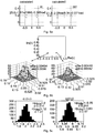
- Fig. 5a shows the received spectral points ⁇ j,ref-i labeled by 'received' and the calculated points labeled by 'calculated' and obtained by multiplication of simulated transmitted spectra with an all-pass filter H (see also middle part in Fig.2 ). Even though the received and calculated points are not identical, they may be similar, e.g. deviate by no more than a predefined Euclidean distance.
- Fig. 5b shows 3D histograms of ⁇ j values, or, in other words, a 3D visualization of the received spectral points of Fig. 5a .
- the x- and y-axes each display an interval spanning 0.03 units in complex frequency space, and the z-axis an amplitude q d ( ⁇ j ), respectively. It may be seen from Fig. 5b , that the spectral points correspond to a local maximum of the amplitude q d ( ⁇ j ).
- Fig. 5c shows histograms of phases of complex amplitudes q d at frequencies ⁇ j .
- Fig. 6 shows a block diagram of an embodiment of a method 600 for a receiver.
- Method 600 comprises a transforming 610 of a received time domain signal to a spectral receive signal.
- Method 600 further comprises a detecting 620 of a transmit signal based on a comparison of the spectral receive signal with at least one of a plurality of hypothetical spectral receive signals.
- a hypothetical spectral receive signal corresponds to a respective hypothetical transmit signal.
- Method 600 also comprises an updating 630 of a hypothetical spectral receive signal of the plurality based on at least one previous spectral receive signal that led to a detection of the transmit signal corresponding to the hypothetical spectral receive signal.
- the precision of the discrete spectrum part may be stable under noise.
- propagation calculated in the frequency domain may deviate to some extend from measured results.
- the aforementioned embodiments may offer a possibility to provide a trainings sequence based channel estimation for these discrete frequencies points and their amplitudes.
- Signal transformation circuitry 700 comprises a first transform module 710 configured to transform a time domain signal 720 to a complex frequency domain signal 730.
- Signal transformation circuitry 700 further comprises a second transform module 740 configured to perform an inverse transformation based on a non-zero imaginary part of complex frequency domain signal 730 to obtain a modified time domain signal 750.
- a better use of existing signal power, e.g. in optical applications, may thus be achieved.
- this may enable a possibility for signal preprocessing, e.g. for a transmitter, that may lessen distortion effects during transmission and hence simplify signal detection on a receiver side.
- Signal transformation circuitry 700 may be suitable for a transmitter.
- Time domain signal 720 may hence be a transmit signal.
- First transform module 710 and second transform module 740 may in a different embodiment be implemented as a common physical unit, for instance a microprocessor or any other programmable hardware component, or also comprise one another.
- signal transformation circuitry 700 may be comprised by a transmitter.
- Said transmitter may have a transmission interface configured to provide modified time domain signal 750 as a transmit signal.
- the transmission interface is in one embodiment coupled to an optical transmission channel, e.g. a fiber, and hence the transmit signal may be an optical signal.
- the signals may just as well be electronic signals.
- Complex frequency domain signal 730 may comprise a real- or complex-valued amplitude plotted against complex-valued frequency. That is to say, complex frequency domain signal 730 may comprise one or more couples of values, each couple formed by a complex frequency and a real- or complex-valued amplitude assigned to each other.
- Time domain signal 720 and modified time domain signal 750 may, accordingly, comprise a real- or complex-valued amplitude plotted against time.
- time domain signal 720 may be limited and/or predetermined in bandwidth.
- second transform module 740 is configured to perform an inverse transformation taking into account only a non-zero imaginary part of complex frequency domain signal 730 to obtain a modified time domain signal 750.
- complex frequency domain signal 730 may comprise one or more complex frequencies. Said one or more complex frequencies may result directly from the transformation performed by first transform module 710.
- first transform module 710 is further configured to obtain the one or more complex frequencies in the upper or lower complex half-plane from the transformation of time domain signal 720.
- Second transform module 740 is in some embodiments configured to perform the inverse transformation based on one or more complex frequencies in the upper or lower complex half-plane. In an embodiment, Second transform module 740 is even configured to perform the inverse transformation taking into account only one or more complex frequencies in the upper or lower complex half-plane. In other words, a part of the complex space may be excluded from the inverse transformation. This part may comprise complex frequencies with an imaginary part equal to zero, or the real axis. In another embodiment, said part of complex space may comprise a predetermined interval around the real axis. Second transform module 740 may then perform the transformation if (or only if) an imaginary part of one or more complex frequencies is outside the interval, or if an absolute value of the imaginary part exceeds a predetermined threshold.
- signal transformation circuitry 700 relates to a communication system, which further comprises one of the aforementioned embodiments related to receiver 300 (compare Fig. 3 ).
- a receiver-sided signal detection process may disregard complex frequencies having an imaginary part equal to zero and amplitude values assigned to the former.
- This portion of complex frequency domain signal 730 corresponds e.g. to the continuous spectrum q c ( ⁇ ) in the right-hand insets of Figs. 1 and 2 . Disregarding this portion may be motivated due to a relative amount of power in this portion, which is reduced when signal power of symbols is increased. A further motivation may arise from an increased variance of the continuous spectrum q c ( ⁇ ) close to soliton propagation which may degrade decisions based on the continuous spectrum.
- signals are created, or, in other words, time domain signals 720 are modified in a way that the modified time domain signal 750 may be limited in bandwidth, but carries low or no energy in the continuous spectrum q c ( ⁇ ).
- Said modification may in one embodiment be accomplished by signal transformation circuitry 800 shown in Fig. 8 .
- Components therein corresponding to like components in Fig. 7 are not explained again. In the following section, differences to Fig. 7 are rather lined out.
- a signal generator 810 comprises a bit-to-symbol mapper 820 to receive a given configuration of data bits 830 and a pulse former 840 to generate time domain signal 720, which is illustrated herein an amplitude-versus-time diagram.
- First transform module 710 is in some embodiments configured to transform time domain signal 720 to complex frequency domain signal 730 using a nonlinear transformation.
- the nonlinear transformation may in further embodiments be a nonlinear Fourier transform (NFT), as shown in Fig. 8 .
- NFT nonlinear Fourier transform
- a discrete Fourier transform, fast Fourier transform or any linear transformation may just as well be used.
- Second transform module 740 is in some embodiments configured to transform complex frequency domain signal 730 at least partially to modified time domain signal 720 using an inverse nonlinear transformation.
- the inverse nonlinear transformation may in further embodiments be a corresponding inverse operation to the transformation performed by first transform module 710. Accordingly, in Fig. 8 , the inverse nonlinear transformation is an inverse nonlinear Fourier transform (INFT).
- an inverse operation to a discrete Fourier transform, fast Fourier transform or any linear transformation may for example be used as well.
- the NFT and INFT performed in Fig. 8 may invoke a set of parameters 870 related to a transmission channel, for example the dispersion coefficient of an ideal fiber channel ⁇ 2,NL , the nonlinear coefficient of the fiber channel ⁇ NL , the length of the fiber channel L NL , and the mean signal power P NL .
- Modified time domain signal 750 is further provided to a modulator 850 by second transform module 740.
- Modulator 850 is configured to provide a modulated modified time domain signal 860.
- second transform module 740 is configured to set a value (e.g. amplitude) of complex frequency domain signal 730 to zero if a complex frequency assigned to the value (e.g. amplitude) of complex frequency domain signal 730 is a real number value, or if an imaginary part of the complex frequency lies within a predetermined interval comprising zero. That is, the discrete part of the spectrum ( ⁇ j and q d ( ⁇ j ) is used unchanged for the inverse transformation, while the continuous part (q c ( ⁇ )) is set to 0 before the inverse transformation.
- complex frequencies ⁇ j with an imaginary part different from zero and amplitudes q d ( ⁇ j ) that are assigned to said complex frequencies or equal zero may then be used.
- complex frequency domain signal 730 may be depicted in a 3D diagram as a real- or complex-valued amplitude plotted against complex-valued frequency (see e.g. Fig. 5b for comparison).
- the amplitude may exhibit at least a local maximum or pole assigned to a complex frequency with an imaginary part larger than zero.
- the complex frequency may correspond to an eigenvalue related to the transformation.
- the local maximum or pole corresponds to a soliton of the modified time domain signal.
- At least 50 per cent of a signal power of modified time domain signal 750 is caused by solitons.
- less than 5 per cent of the modified time domain signal is caused by a fraction of complex frequency domain signal 730, which is assigned to a complex frequency with an imaginary part equal to zero. That is to say, less than 5 per cent or even none of the signal power originates from the continuous portion q c ( ⁇ ) of complex frequency domain signal 730. It is thus possible to provide a preprocessed signal for transmission in a way that may simplify signal detection on a receiver side due to better agreement of complex frequency points of the received signal and a reference signal.
- the INFT may correspond to a Darboux transformation (DT), whose equations are presented in the following.
- the non-canonical eigenvectors v(t, ⁇ j ) may be written as [ A j e -j ⁇ j t ,B j e j ⁇ j t ] T .
- the coefficients A j and B j control the spectral amplitudes and the shape of the pulses, and may be determined from the discrete amplitude q d ( ⁇ j ).
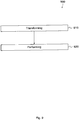
- Fig. 9 further shows a block diagram of an embodiment of a method 900 for a signal transformation circuitry.
- Method 900 comprises a transforming 910 of a time domain transmit signal to a complex frequency domain transmit signal.
- Method 900 further comprises a performing 920 of an inverse transformation based on a non-zero imaginary part of the complex frequency domain signal to obtain a modified time domain signal.
- Embodiments may improve or even optimize the sensitivity of these schemes. With increasing launch power (or increasing fiber nonlinearity) the relative amount of power in the continuous part of the nonlinear spectrum may decrease. Embodiments may present a possibility to preprocess a transmitter signal by transforming an initial bandwidth limited transmitter signal to a similar, refined transmitter signal, which contains only or dominantly discrete spectral components (higher order solitons). These exemplary spectra may possibly be more efficiently detected by a receiver, for example receiver 300 presented in the embodiment of Fig. 3 .
- the optical communication system may comprise an optical transmission channel, for instance an optical fiber, and a transmitter comprising the aforementioned signal transformation circuitry.
- the signal transformation circuitry may be coupled to the optical fiber.
- the optical communication system may comprise the aforementioned receiver, and the receiver may be coupled to the optical fiber.
- the set of channel parameters 870 (P NL , L NL , ⁇ NL , ⁇ 2,NL ) of the NFT are shown in the bottom center box and are also used in the equations in left box of Fig.1 .
- the nonlinear coefficient ⁇ NL and the dispersion coefficient ⁇ 2,NL are kept at values that are true for the fiber used, or deviate by no more than 5 per cent from these (e.g. 1.15 km -1 W -1 and 17 ps/nm/km, respectively).
- the NFT power P NL is set equal to P ⁇ L eff /L span .
- values of channel-related parameters, which are used for the mathematical NFT operation may be quantified in some embodiments. This embodiment may be helpful for some schemes applying NFT in a realistic fiber link, like for example the previously presented embodiments.
- a further embodiment is a computer readable storage medium storing instructions which, when executed by a computer, cause the computer to implement one of the methods described herein.
- Other embodiments are a computer program or a computer program product having a program code for performing any one of the above described methods, when the computer program or computer program product is executed on a processor, computer, or programmable hardware.
- program storage devices e.g., digital data storage media, which are machine or computer readable and encode machine-executable or computer-executable programs of instructions where said instructions perform some or all of the steps of methods described herein.
- the program storage devices may be, e.g., digital memories, magnetic storage media such as magnetic disks and magnetic tapes, hard drives, or optically readable digital data storage media.
- the embodiments are also intended to cover computers programmed to perform said steps of methods described herein or (field) programmable logic arrays ((F)PLAs) or (field) programmable gate arrays ((F)PGAs), programmed to perform said steps of the above-described methods.
- any functional block described herein may correspond to or be implemented as "one or more modules", “one or more devices”, “one or more units”, etc.
- the functions may be provided by a single dedicated processor, by a single shared processor, or by a plurality of individual processors, some of which may be shared.
- explicit use of the term "processor” or “controller” should not be construed to refer exclusively to hardware capable of executing software, and may implicitly include, without limitation, digital signal processor (DSP) hardware, network processor, application specific integrated circuit (ASIC), field programmable gate array (FPGA), read only memory (ROM) for storing software, random access memory (RAM), and non-volatile storage. Other hardware, conventional and/or custom, may also be included.
- DSP digital signal processor
- ASIC application specific integrated circuit
- FPGA field programmable gate array
- ROM read only memory
- RAM random access memory
- non-volatile storage Other hardware, conventional and/or custom, may also be included.
- any block diagrams herein represent conceptual views of illustrative circuitry embodying the principles of the invention.
- any flow charts, flow diagrams, state transition diagrams, pseudo code, and the like represent various processes which may be substantially represented in computer readable medium and so executed by a computer or processor, whether or not such computer or processor is explicitly shown.
Landscapes
- Engineering & Computer Science (AREA)
- Computer Networks & Wireless Communication (AREA)
- Signal Processing (AREA)
- Physics & Mathematics (AREA)
- Electromagnetism (AREA)
- Discrete Mathematics (AREA)
- General Physics & Mathematics (AREA)
- Mathematical Physics (AREA)
- Nonlinear Science (AREA)
- Optical Communication System (AREA)
Claims (13)
- Circuit de transformation de signal (700; 800), comprenant :un premier module de transformation (710) configuré pour transformer, par le biais d'une transformation de Fourier non-linéaire, un signal de domaine de temps (720) en un signal de domaine de fréquence complexe (730), selon lequel le signal de domaine de fréquence complexe (730) comprend une partie spectrale à valeur complexe comprenant une ou plusieurs fréquences complexes ; etun deuxième module de transformation (740) configuré pour effectuer une transformation de Fourier non-linéaire inverse sur la base d'une partie imaginaire non-zéro du signal de domaine de fréquence complexe (730) afin d'obtenir un signal de domaine de temps modifié (750), et configuré pour effectuer la transformation de Fourier non-linéaire inverse sur la base d'une ou plusieurs fréquences complexes du demi-plan complexe supérieur ou inférieur.
- Circuit de transformation de signal (700; 800) selon la revendication 1, selon lequel le premier module de transformation (710) est en outre configuré pour obtenir la ou les plusieurs fréquences complexes dans le demi-plan complexe supérieur ou inférieur à partir de la transformation du signal du domaine de temps (720).
- Circuit de transformation de signal (700; 800) selon la revendication 1, selon lequel le deuxième module de transformation (740) est configuré pour effectuer la transformation de Fourier non-linéaire inverse si une partie imaginaire de la ou des plusieurs fréquences complexes se situent en dehors d'un intervalle prédéterminé comprenant le zéro.
- Circuit de transformation de signal (700; 800) selon la revendication 1, selon lequel le deuxième module de transformation (740) est en outre configuré pour définir une valeur du signal de domaine de fréquence complexe (730) à zéro si une fréquence complexe attribuée à la valeur du signal de domaine de fréquence complexe (730) est une valeur de nombre réel.
- Circuit de transformation de signal (700; 800) selon la revendication 1, selon lequel le deuxième module de transformation (740) est en outre configuré pour effectuer la transformation de Fourier non-linéaire inverse en :utilisant une fréquence complexe ayant une partie imaginaire non-zéro et une valeur de signal de domaine de fréquence complexe (730) si la valeur est attribuée à la fréquence complexe ou si la valeur est égale à zéro.
- Circuit de transformation de signal (700; 800) selon la revendication 1, selon lequel le deuxième module de transformation (740) est en outre configuré pour effectuer la transformation de Fourier non-linéaire inverse correspondant à une transformation de Darboux.
- Circuit de transformation de signal (700; 800) selon la revendication 1, selon lequel le signal de domaine de fréquence complexe (730) présente au moins un maximum local ou un pôle attribué à une fréquence complexe ayant une partie imaginaire qui est supérieure à zéro, et selon lequel le deuxième module de transformation (740) est configuré pour obtenir le signal de domaine de temps modifié (750) à partir de la transformation de Fourier non-linéaire en tant que signal optique, selon lequel le au moins un maximum local ou pôle correspond à au moins un soliton du signal de domaine de temps modifié (750).
- Circuit de transformation de signal (700; 800) selon la revendication 1, selon lequel le deuxième module de transformation (740) est configuré pour obtenir le signal de domaine de temps modifié (750) à partir de la transformation de Fourier non-linéaire en tant que signal optique, selon lequel au moins 50 pour cent d'une puissance de signal du signal de domaine de temps modifié (750) proviennent d'un ou de plusieurs solitons du signal de domaine de temps modifié (750).
- Circuit de transformation de signal (700; 800) selon la revendication 1, selon lequel le deuxième module de transformation (740) est configuré pour obtenir le signal de domaine de temps modifié (750) à partir de la transformation de Fourier non-linéaire en tant que signal optique, selon lequel moins de 5 pour cent d'une puissance de signal du signal de domaine de temps modifié (750) proviennent d'une fraction du signal de domaine de fréquence complexe (730) attribuée à une fréquence complexe ayant une partie imaginaire égale à zéro.
- Émetteur comprenant :le circuit de transformation de signal (700; 800) selon la revendication 1 ; etune interface de transmission configurée pour fournir le signal de domaine de temps modifié en tant que signal de transmission.
- L'émetteur selon la revendication 10, selon lequel l'interface de transmission est couplée à un canal de transmission optique, et selon lequel le signal de transmission est un signal optique.
- Procédé (900) d'un circuit de transformation de signal, comprenant :la transformation (910), par le biais d'une transformation de Fourier non-linéaire, d'un signal de domaine de temps (720) en un signal de domaine de fréquence complexe (730), selon lequel le signal de domaine de fréquence complexe (730) comprend une ou plusieurs fréquences complexes ; etl'exécution (920) d'une transformation de Fourier non-linéaire inverse sur la base d'une partie imaginaire non-zéro du signal de domaine de fréquence complexe, afin d'obtenir un signal de domaine de temps modifié, et sur la base d'une ou plusieurs fréquences complexes du demi-plan complexe supérieur ou inférieur.
- Programme d'ordinateur présentant du code de programmation pour la mise en oeuvre du procédé selon la revendication 12, selon lequel le programme d'ordinateur est exécuté sur un ordinateur ou sur un processeur.
Priority Applications (1)
| Application Number | Priority Date | Filing Date | Title |
|---|---|---|---|
| EP14307102.5A EP3035623B1 (fr) | 2014-12-19 | 2014-12-19 | Prétraitement pour un émetteur optique basé sur une transformée de Fourier non linéaire |
Applications Claiming Priority (1)
| Application Number | Priority Date | Filing Date | Title |
|---|---|---|---|
| EP14307102.5A EP3035623B1 (fr) | 2014-12-19 | 2014-12-19 | Prétraitement pour un émetteur optique basé sur une transformée de Fourier non linéaire |
Publications (2)
| Publication Number | Publication Date |
|---|---|
| EP3035623A1 EP3035623A1 (fr) | 2016-06-22 |
| EP3035623B1 true EP3035623B1 (fr) | 2020-02-05 |
Family
ID=52394850
Family Applications (1)
| Application Number | Title | Priority Date | Filing Date |
|---|---|---|---|
| EP14307102.5A Active EP3035623B1 (fr) | 2014-12-19 | 2014-12-19 | Prétraitement pour un émetteur optique basé sur une transformée de Fourier non linéaire |
Country Status (1)
| Country | Link |
|---|---|
| EP (1) | EP3035623B1 (fr) |
Families Citing this family (1)
| Publication number | Priority date | Publication date | Assignee | Title |
|---|---|---|---|---|
| CN111385029B (zh) * | 2018-12-28 | 2022-09-13 | 中兴通讯股份有限公司 | 光纤非线性损伤补偿方法及装置 |
-
2014
- 2014-12-19 EP EP14307102.5A patent/EP3035623B1/fr active Active
Non-Patent Citations (1)
| Title |
|---|
| None * |
Also Published As
| Publication number | Publication date |
|---|---|
| EP3035623A1 (fr) | 2016-06-22 |
Similar Documents
| Publication | Publication Date | Title |
|---|---|---|
| Wang et al. | Data-driven optical fiber channel modeling: A deep learning approach | |
| Jihad et al. | Evaluation of impairment mitigations for optical fiber communications using dispersion compensation techniques | |
| US10270537B2 (en) | Method and system for nonlinear interference mitigation | |
| US20050175339A1 (en) | Dynamic broadband optical equalizer | |
| Kamalian et al. | On the design of NFT-based communication systems with lumped amplification | |
| CN104980379A (zh) | 非线性失真的估计装置、方法以及接收机 | |
| CN103067084A (zh) | 对多模光纤的给定比特错误率的功率损失进行评估的方法 | |
| US9825708B2 (en) | Compensation apparatus and method for inter-channel nonlinear damage | |
| Zhang et al. | Correlated eigenvalues of multi-soliton optical communications | |
| EP3143708B1 (fr) | Égalisation d'affaiblissement de propagation non linéaire | |
| EP3035564A1 (fr) | Prétraitement et détection pour un récepteur optique basé sur une transformée de Fourier non linéaire | |
| EP3035623A1 (fr) | Prétraitement pour un émetteur optique basé sur une transformée de Fourier non linéaire | |
| Aref et al. | An efficient nonlinear Fourier transform algorithm for detection of eigenvalues from continuous spectrum | |
| EP2993849A1 (fr) | Prétraitement et détection pour un récepteur optique basé sur une transformée de Fourier non linéaire | |
| Aamir et al. | Fiber parameter identification and monitoring using a Koopman-based identification method | |
| EP4107878B1 (fr) | Détermination de la dispersion chromatique dans une liaison optique | |
| Uduagbomen et al. | Physics-informed neural network for fibre channel modelling in optical communication systems | |
| de Koster et al. | Experimental investigation of nonlinear Fourier transform based fibre nonlinearity characterisation | |
| Aref | Nonlinear fourier transform of truncated multi-soliton pulses | |
| Fayzullayeva et al. | Analysis of chromatic dispersion on the performance of a standard single mode fiber-optics communication systems | |
| Mohammed et al. | Analysis of Dispersion Compensation in a Single Mode Optical Fiber Communication System | |
| CN118414796A (zh) | 光传输特性估计装置、光传输特性估计方法及程序 | |
| Kaliteevskiy et al. | Power penalties for multi-level PAM modulation formats at arbitrary bit error rates | |
| de Koster et al. | Fibre model identification for nonlinear Fourier transform-based transmission | |
| Pratama et al. | Optimizing Optical Signal Quality with Deep Learning Dispersion Compensation at Various Distances |
Legal Events
| Date | Code | Title | Description |
|---|---|---|---|
| PUAI | Public reference made under article 153(3) epc to a published international application that has entered the european phase |
Free format text: ORIGINAL CODE: 0009012 |
|
| AK | Designated contracting states |
Kind code of ref document: A1 Designated state(s): AL AT BE BG CH CY CZ DE DK EE ES FI FR GB GR HR HU IE IS IT LI LT LU LV MC MK MT NL NO PL PT RO RS SE SI SK SM TR |
|
| AX | Request for extension of the european patent |
Extension state: BA ME |
|
| STAA | Information on the status of an ep patent application or granted ep patent |
Free format text: STATUS: REQUEST FOR EXAMINATION WAS MADE |
|
| 17P | Request for examination filed |
Effective date: 20161222 |
|
| RBV | Designated contracting states (corrected) |
Designated state(s): AL AT BE BG CH CY CZ DE DK EE ES FI FR GB GR HR HU IE IS IT LI LT LU LV MC MK MT NL NO PL PT RO RS SE SI SK SM TR |
|
| RAP1 | Party data changed (applicant data changed or rights of an application transferred) |
Owner name: ALCATEL LUCENT |
|
| GRAP | Despatch of communication of intention to grant a patent |
Free format text: ORIGINAL CODE: EPIDOSNIGR1 |
|
| STAA | Information on the status of an ep patent application or granted ep patent |
Free format text: STATUS: GRANT OF PATENT IS INTENDED |
|
| INTG | Intention to grant announced |
Effective date: 20190913 |
|
| GRAS | Grant fee paid |
Free format text: ORIGINAL CODE: EPIDOSNIGR3 |
|
| GRAA | (expected) grant |
Free format text: ORIGINAL CODE: 0009210 |
|
| STAA | Information on the status of an ep patent application or granted ep patent |
Free format text: STATUS: THE PATENT HAS BEEN GRANTED |
|
| AK | Designated contracting states |
Kind code of ref document: B1 Designated state(s): AL AT BE BG CH CY CZ DE DK EE ES FI FR GB GR HR HU IE IS IT LI LT LU LV MC MK MT NL NO PL PT RO RS SE SI SK SM TR |
|
| REG | Reference to a national code |
Ref country code: GB Ref legal event code: FG4D |
|
| REG | Reference to a national code |
Ref country code: AT Ref legal event code: REF Ref document number: 1230673 Country of ref document: AT Kind code of ref document: T Effective date: 20200215 |
|
| REG | Reference to a national code |
Ref country code: DE Ref legal event code: R096 Ref document number: 602014060588 Country of ref document: DE |
|
| REG | Reference to a national code |
Ref country code: IE Ref legal event code: FG4D |
|
| REG | Reference to a national code |
Ref country code: CH Ref legal event code: EP |
|
| REG | Reference to a national code |
Ref country code: NL Ref legal event code: MP Effective date: 20200205 |
|
| PG25 | Lapsed in a contracting state [announced via postgrant information from national office to epo] |
Ref country code: FI Free format text: LAPSE BECAUSE OF FAILURE TO SUBMIT A TRANSLATION OF THE DESCRIPTION OR TO PAY THE FEE WITHIN THE PRESCRIBED TIME-LIMIT Effective date: 20200205 Ref country code: RS Free format text: LAPSE BECAUSE OF FAILURE TO SUBMIT A TRANSLATION OF THE DESCRIPTION OR TO PAY THE FEE WITHIN THE PRESCRIBED TIME-LIMIT Effective date: 20200205 Ref country code: PT Free format text: LAPSE BECAUSE OF FAILURE TO SUBMIT A TRANSLATION OF THE DESCRIPTION OR TO PAY THE FEE WITHIN THE PRESCRIBED TIME-LIMIT Effective date: 20200628 Ref country code: NO Free format text: LAPSE BECAUSE OF FAILURE TO SUBMIT A TRANSLATION OF THE DESCRIPTION OR TO PAY THE FEE WITHIN THE PRESCRIBED TIME-LIMIT Effective date: 20200505 |
|
| REG | Reference to a national code |
Ref country code: LT Ref legal event code: MG4D |
|
| PG25 | Lapsed in a contracting state [announced via postgrant information from national office to epo] |
Ref country code: BG Free format text: LAPSE BECAUSE OF FAILURE TO SUBMIT A TRANSLATION OF THE DESCRIPTION OR TO PAY THE FEE WITHIN THE PRESCRIBED TIME-LIMIT Effective date: 20200505 Ref country code: IS Free format text: LAPSE BECAUSE OF FAILURE TO SUBMIT A TRANSLATION OF THE DESCRIPTION OR TO PAY THE FEE WITHIN THE PRESCRIBED TIME-LIMIT Effective date: 20200605 Ref country code: LV Free format text: LAPSE BECAUSE OF FAILURE TO SUBMIT A TRANSLATION OF THE DESCRIPTION OR TO PAY THE FEE WITHIN THE PRESCRIBED TIME-LIMIT Effective date: 20200205 Ref country code: SE Free format text: LAPSE BECAUSE OF FAILURE TO SUBMIT A TRANSLATION OF THE DESCRIPTION OR TO PAY THE FEE WITHIN THE PRESCRIBED TIME-LIMIT Effective date: 20200205 Ref country code: GR Free format text: LAPSE BECAUSE OF FAILURE TO SUBMIT A TRANSLATION OF THE DESCRIPTION OR TO PAY THE FEE WITHIN THE PRESCRIBED TIME-LIMIT Effective date: 20200506 Ref country code: HR Free format text: LAPSE BECAUSE OF FAILURE TO SUBMIT A TRANSLATION OF THE DESCRIPTION OR TO PAY THE FEE WITHIN THE PRESCRIBED TIME-LIMIT Effective date: 20200205 |
|
| PG25 | Lapsed in a contracting state [announced via postgrant information from national office to epo] |
Ref country code: NL Free format text: LAPSE BECAUSE OF FAILURE TO SUBMIT A TRANSLATION OF THE DESCRIPTION OR TO PAY THE FEE WITHIN THE PRESCRIBED TIME-LIMIT Effective date: 20200205 |
|
| PG25 | Lapsed in a contracting state [announced via postgrant information from national office to epo] |
Ref country code: ES Free format text: LAPSE BECAUSE OF FAILURE TO SUBMIT A TRANSLATION OF THE DESCRIPTION OR TO PAY THE FEE WITHIN THE PRESCRIBED TIME-LIMIT Effective date: 20200205 Ref country code: CZ Free format text: LAPSE BECAUSE OF FAILURE TO SUBMIT A TRANSLATION OF THE DESCRIPTION OR TO PAY THE FEE WITHIN THE PRESCRIBED TIME-LIMIT Effective date: 20200205 Ref country code: RO Free format text: LAPSE BECAUSE OF FAILURE TO SUBMIT A TRANSLATION OF THE DESCRIPTION OR TO PAY THE FEE WITHIN THE PRESCRIBED TIME-LIMIT Effective date: 20200205 Ref country code: DK Free format text: LAPSE BECAUSE OF FAILURE TO SUBMIT A TRANSLATION OF THE DESCRIPTION OR TO PAY THE FEE WITHIN THE PRESCRIBED TIME-LIMIT Effective date: 20200205 Ref country code: SM Free format text: LAPSE BECAUSE OF FAILURE TO SUBMIT A TRANSLATION OF THE DESCRIPTION OR TO PAY THE FEE WITHIN THE PRESCRIBED TIME-LIMIT Effective date: 20200205 Ref country code: LT Free format text: LAPSE BECAUSE OF FAILURE TO SUBMIT A TRANSLATION OF THE DESCRIPTION OR TO PAY THE FEE WITHIN THE PRESCRIBED TIME-LIMIT Effective date: 20200205 Ref country code: EE Free format text: LAPSE BECAUSE OF FAILURE TO SUBMIT A TRANSLATION OF THE DESCRIPTION OR TO PAY THE FEE WITHIN THE PRESCRIBED TIME-LIMIT Effective date: 20200205 Ref country code: SK Free format text: LAPSE BECAUSE OF FAILURE TO SUBMIT A TRANSLATION OF THE DESCRIPTION OR TO PAY THE FEE WITHIN THE PRESCRIBED TIME-LIMIT Effective date: 20200205 |
|
| REG | Reference to a national code |
Ref country code: DE Ref legal event code: R097 Ref document number: 602014060588 Country of ref document: DE |
|
| REG | Reference to a national code |
Ref country code: AT Ref legal event code: MK05 Ref document number: 1230673 Country of ref document: AT Kind code of ref document: T Effective date: 20200205 |
|
| PLBE | No opposition filed within time limit |
Free format text: ORIGINAL CODE: 0009261 |
|
| STAA | Information on the status of an ep patent application or granted ep patent |
Free format text: STATUS: NO OPPOSITION FILED WITHIN TIME LIMIT |
|
| 26N | No opposition filed |
Effective date: 20201106 |
|
| PG25 | Lapsed in a contracting state [announced via postgrant information from national office to epo] |
Ref country code: AT Free format text: LAPSE BECAUSE OF FAILURE TO SUBMIT A TRANSLATION OF THE DESCRIPTION OR TO PAY THE FEE WITHIN THE PRESCRIBED TIME-LIMIT Effective date: 20200205 Ref country code: IT Free format text: LAPSE BECAUSE OF FAILURE TO SUBMIT A TRANSLATION OF THE DESCRIPTION OR TO PAY THE FEE WITHIN THE PRESCRIBED TIME-LIMIT Effective date: 20200205 |
|
| PG25 | Lapsed in a contracting state [announced via postgrant information from national office to epo] |
Ref country code: PL Free format text: LAPSE BECAUSE OF FAILURE TO SUBMIT A TRANSLATION OF THE DESCRIPTION OR TO PAY THE FEE WITHIN THE PRESCRIBED TIME-LIMIT Effective date: 20200205 Ref country code: SI Free format text: LAPSE BECAUSE OF FAILURE TO SUBMIT A TRANSLATION OF THE DESCRIPTION OR TO PAY THE FEE WITHIN THE PRESCRIBED TIME-LIMIT Effective date: 20200205 |
|
| REG | Reference to a national code |
Ref country code: CH Ref legal event code: PL |
|
| PG25 | Lapsed in a contracting state [announced via postgrant information from national office to epo] |
Ref country code: MC Free format text: LAPSE BECAUSE OF FAILURE TO SUBMIT A TRANSLATION OF THE DESCRIPTION OR TO PAY THE FEE WITHIN THE PRESCRIBED TIME-LIMIT Effective date: 20200205 |
|
| REG | Reference to a national code |
Ref country code: BE Ref legal event code: MM Effective date: 20201231 |
|
| PG25 | Lapsed in a contracting state [announced via postgrant information from national office to epo] |
Ref country code: LU Free format text: LAPSE BECAUSE OF NON-PAYMENT OF DUE FEES Effective date: 20201219 Ref country code: IE Free format text: LAPSE BECAUSE OF NON-PAYMENT OF DUE FEES Effective date: 20201219 |
|
| PG25 | Lapsed in a contracting state [announced via postgrant information from national office to epo] |
Ref country code: CH Free format text: LAPSE BECAUSE OF NON-PAYMENT OF DUE FEES Effective date: 20201231 Ref country code: LI Free format text: LAPSE BECAUSE OF NON-PAYMENT OF DUE FEES Effective date: 20201231 |
|
| REG | Reference to a national code |
Ref country code: DE Ref legal event code: R082 Ref document number: 602014060588 Country of ref document: DE Representative=s name: METACOM LEGAL RECHTSANWAELTE, DE Ref country code: DE Ref legal event code: R082 Ref document number: 602014060588 Country of ref document: DE Representative=s name: METACOM LEGAL, DE Ref country code: DE Ref legal event code: R082 Ref document number: 602014060588 Country of ref document: DE Representative=s name: METACOM LEGAL NAGEL MARKOWSKY VOSSIUS RECHTSAN, DE |
|
| PG25 | Lapsed in a contracting state [announced via postgrant information from national office to epo] |
Ref country code: TR Free format text: LAPSE BECAUSE OF FAILURE TO SUBMIT A TRANSLATION OF THE DESCRIPTION OR TO PAY THE FEE WITHIN THE PRESCRIBED TIME-LIMIT Effective date: 20200205 Ref country code: MT Free format text: LAPSE BECAUSE OF FAILURE TO SUBMIT A TRANSLATION OF THE DESCRIPTION OR TO PAY THE FEE WITHIN THE PRESCRIBED TIME-LIMIT Effective date: 20200205 Ref country code: CY Free format text: LAPSE BECAUSE OF FAILURE TO SUBMIT A TRANSLATION OF THE DESCRIPTION OR TO PAY THE FEE WITHIN THE PRESCRIBED TIME-LIMIT Effective date: 20200205 |
|
| PG25 | Lapsed in a contracting state [announced via postgrant information from national office to epo] |
Ref country code: MK Free format text: LAPSE BECAUSE OF FAILURE TO SUBMIT A TRANSLATION OF THE DESCRIPTION OR TO PAY THE FEE WITHIN THE PRESCRIBED TIME-LIMIT Effective date: 20200205 Ref country code: AL Free format text: LAPSE BECAUSE OF FAILURE TO SUBMIT A TRANSLATION OF THE DESCRIPTION OR TO PAY THE FEE WITHIN THE PRESCRIBED TIME-LIMIT Effective date: 20200205 |
|
| PG25 | Lapsed in a contracting state [announced via postgrant information from national office to epo] |
Ref country code: BE Free format text: LAPSE BECAUSE OF NON-PAYMENT OF DUE FEES Effective date: 20201231 |
|
| P01 | Opt-out of the competence of the unified patent court (upc) registered |
Effective date: 20230606 |
|
| PGFP | Annual fee paid to national office [announced via postgrant information from national office to epo] |
Ref country code: DE Payment date: 20250529 Year of fee payment: 11 |
|
| PGFP | Annual fee paid to national office [announced via postgrant information from national office to epo] |
Ref country code: GB Payment date: 20250527 Year of fee payment: 11 |
|
| PGFP | Annual fee paid to national office [announced via postgrant information from national office to epo] |
Ref country code: FR Payment date: 20250526 Year of fee payment: 11 |