EP3036121B1 - Steuerung für elektrisches hybridfahrzeug und verfahren - Google Patents
Steuerung für elektrisches hybridfahrzeug und verfahren Download PDFInfo
- Publication number
- EP3036121B1 EP3036121B1 EP14752888.9A EP14752888A EP3036121B1 EP 3036121 B1 EP3036121 B1 EP 3036121B1 EP 14752888 A EP14752888 A EP 14752888A EP 3036121 B1 EP3036121 B1 EP 3036121B1
- Authority
- EP
- European Patent Office
- Prior art keywords
- powertrain
- mode
- engine
- vehicle
- controller
- Prior art date
- Legal status (The legal status is an assumption and is not a legal conclusion. Google has not performed a legal analysis and makes no representation as to the accuracy of the status listed.)
- Active
Links
Images


Classifications
-
- B—PERFORMING OPERATIONS; TRANSPORTING
- B60—VEHICLES IN GENERAL
- B60W—CONJOINT CONTROL OF VEHICLE SUB-UNITS OF DIFFERENT TYPE OR DIFFERENT FUNCTION; CONTROL SYSTEMS SPECIALLY ADAPTED FOR HYBRID VEHICLES; ROAD VEHICLE DRIVE CONTROL SYSTEMS FOR PURPOSES NOT RELATED TO THE CONTROL OF A PARTICULAR SUB-UNIT
- B60W20/00—Control systems specially adapted for hybrid vehicles
-
- B—PERFORMING OPERATIONS; TRANSPORTING
- B60—VEHICLES IN GENERAL
- B60W—CONJOINT CONTROL OF VEHICLE SUB-UNITS OF DIFFERENT TYPE OR DIFFERENT FUNCTION; CONTROL SYSTEMS SPECIALLY ADAPTED FOR HYBRID VEHICLES; ROAD VEHICLE DRIVE CONTROL SYSTEMS FOR PURPOSES NOT RELATED TO THE CONTROL OF A PARTICULAR SUB-UNIT
- B60W20/00—Control systems specially adapted for hybrid vehicles
- B60W20/40—Controlling the engagement or disengagement of prime movers, e.g. for transition between prime movers
-
- B—PERFORMING OPERATIONS; TRANSPORTING
- B60—VEHICLES IN GENERAL
- B60K—ARRANGEMENT OR MOUNTING OF PROPULSION UNITS OR OF TRANSMISSIONS IN VEHICLES; ARRANGEMENT OR MOUNTING OF PLURAL DIVERSE PRIME-MOVERS IN VEHICLES; AUXILIARY DRIVES FOR VEHICLES; INSTRUMENTATION OR DASHBOARDS FOR VEHICLES; ARRANGEMENTS IN CONNECTION WITH COOLING, AIR INTAKE, GAS EXHAUST OR FUEL SUPPLY OF PROPULSION UNITS IN VEHICLES
- B60K6/00—Arrangement or mounting of plural diverse prime-movers for mutual or common propulsion, e.g. hybrid propulsion systems comprising electric motors and internal combustion engines
- B60K6/20—Arrangement or mounting of plural diverse prime-movers for mutual or common propulsion, e.g. hybrid propulsion systems comprising electric motors and internal combustion engines the prime-movers consisting of electric motors and internal combustion engines, e.g. HEVs
- B60K6/42—Arrangement or mounting of plural diverse prime-movers for mutual or common propulsion, e.g. hybrid propulsion systems comprising electric motors and internal combustion engines the prime-movers consisting of electric motors and internal combustion engines, e.g. HEVs characterised by the architecture of the hybrid electric vehicle
- B60K6/48—Parallel type
-
- B—PERFORMING OPERATIONS; TRANSPORTING
- B60—VEHICLES IN GENERAL
- B60K—ARRANGEMENT OR MOUNTING OF PROPULSION UNITS OR OF TRANSMISSIONS IN VEHICLES; ARRANGEMENT OR MOUNTING OF PLURAL DIVERSE PRIME-MOVERS IN VEHICLES; AUXILIARY DRIVES FOR VEHICLES; INSTRUMENTATION OR DASHBOARDS FOR VEHICLES; ARRANGEMENTS IN CONNECTION WITH COOLING, AIR INTAKE, GAS EXHAUST OR FUEL SUPPLY OF PROPULSION UNITS IN VEHICLES
- B60K6/00—Arrangement or mounting of plural diverse prime-movers for mutual or common propulsion, e.g. hybrid propulsion systems comprising electric motors and internal combustion engines
- B60K6/20—Arrangement or mounting of plural diverse prime-movers for mutual or common propulsion, e.g. hybrid propulsion systems comprising electric motors and internal combustion engines the prime-movers consisting of electric motors and internal combustion engines, e.g. HEVs
- B60K6/50—Architecture of the driveline characterised by arrangement or kind of transmission units
- B60K6/52—Driving a plurality of drive axles, e.g. four-wheel drive
-
- B—PERFORMING OPERATIONS; TRANSPORTING
- B60—VEHICLES IN GENERAL
- B60W—CONJOINT CONTROL OF VEHICLE SUB-UNITS OF DIFFERENT TYPE OR DIFFERENT FUNCTION; CONTROL SYSTEMS SPECIALLY ADAPTED FOR HYBRID VEHICLES; ROAD VEHICLE DRIVE CONTROL SYSTEMS FOR PURPOSES NOT RELATED TO THE CONTROL OF A PARTICULAR SUB-UNIT
- B60W10/00—Conjoint control of vehicle sub-units of different type or different function
- B60W10/04—Conjoint control of vehicle sub-units of different type or different function including control of propulsion units
- B60W10/06—Conjoint control of vehicle sub-units of different type or different function including control of propulsion units including control of combustion engines
-
- B—PERFORMING OPERATIONS; TRANSPORTING
- B60—VEHICLES IN GENERAL
- B60W—CONJOINT CONTROL OF VEHICLE SUB-UNITS OF DIFFERENT TYPE OR DIFFERENT FUNCTION; CONTROL SYSTEMS SPECIALLY ADAPTED FOR HYBRID VEHICLES; ROAD VEHICLE DRIVE CONTROL SYSTEMS FOR PURPOSES NOT RELATED TO THE CONTROL OF A PARTICULAR SUB-UNIT
- B60W10/00—Conjoint control of vehicle sub-units of different type or different function
- B60W10/04—Conjoint control of vehicle sub-units of different type or different function including control of propulsion units
- B60W10/08—Conjoint control of vehicle sub-units of different type or different function including control of propulsion units including control of electric propulsion units, e.g. motors or generators
-
- B—PERFORMING OPERATIONS; TRANSPORTING
- B60—VEHICLES IN GENERAL
- B60W—CONJOINT CONTROL OF VEHICLE SUB-UNITS OF DIFFERENT TYPE OR DIFFERENT FUNCTION; CONTROL SYSTEMS SPECIALLY ADAPTED FOR HYBRID VEHICLES; ROAD VEHICLE DRIVE CONTROL SYSTEMS FOR PURPOSES NOT RELATED TO THE CONTROL OF A PARTICULAR SUB-UNIT
- B60W10/00—Conjoint control of vehicle sub-units of different type or different function
- B60W10/24—Conjoint control of vehicle sub-units of different type or different function including control of energy storage means
- B60W10/26—Conjoint control of vehicle sub-units of different type or different function including control of energy storage means for electrical energy, e.g. batteries or capacitors
-
- B—PERFORMING OPERATIONS; TRANSPORTING
- B60—VEHICLES IN GENERAL
- B60W—CONJOINT CONTROL OF VEHICLE SUB-UNITS OF DIFFERENT TYPE OR DIFFERENT FUNCTION; CONTROL SYSTEMS SPECIALLY ADAPTED FOR HYBRID VEHICLES; ROAD VEHICLE DRIVE CONTROL SYSTEMS FOR PURPOSES NOT RELATED TO THE CONTROL OF A PARTICULAR SUB-UNIT
- B60W20/00—Control systems specially adapted for hybrid vehicles
- B60W20/10—Controlling the power contribution of each of the prime movers to meet required power demand
- B60W20/11—Controlling the power contribution of each of the prime movers to meet required power demand using model predictive control [MPC] strategies, i.e. control methods based on models predicting performance
-
- B—PERFORMING OPERATIONS; TRANSPORTING
- B60—VEHICLES IN GENERAL
- B60W—CONJOINT CONTROL OF VEHICLE SUB-UNITS OF DIFFERENT TYPE OR DIFFERENT FUNCTION; CONTROL SYSTEMS SPECIALLY ADAPTED FOR HYBRID VEHICLES; ROAD VEHICLE DRIVE CONTROL SYSTEMS FOR PURPOSES NOT RELATED TO THE CONTROL OF A PARTICULAR SUB-UNIT
- B60W20/00—Control systems specially adapted for hybrid vehicles
- B60W20/10—Controlling the power contribution of each of the prime movers to meet required power demand
- B60W20/13—Controlling the power contribution of each of the prime movers to meet required power demand in order to stay within battery power input or output limits; in order to prevent overcharging or battery depletion
-
- B—PERFORMING OPERATIONS; TRANSPORTING
- B60—VEHICLES IN GENERAL
- B60W—CONJOINT CONTROL OF VEHICLE SUB-UNITS OF DIFFERENT TYPE OR DIFFERENT FUNCTION; CONTROL SYSTEMS SPECIALLY ADAPTED FOR HYBRID VEHICLES; ROAD VEHICLE DRIVE CONTROL SYSTEMS FOR PURPOSES NOT RELATED TO THE CONTROL OF A PARTICULAR SUB-UNIT
- B60W20/00—Control systems specially adapted for hybrid vehicles
- B60W20/10—Controlling the power contribution of each of the prime movers to meet required power demand
- B60W20/15—Control strategies specially adapted for achieving a particular effect
- B60W20/16—Control strategies specially adapted for achieving a particular effect for reducing engine exhaust emissions
-
- B—PERFORMING OPERATIONS; TRANSPORTING
- B60—VEHICLES IN GENERAL
- B60W—CONJOINT CONTROL OF VEHICLE SUB-UNITS OF DIFFERENT TYPE OR DIFFERENT FUNCTION; CONTROL SYSTEMS SPECIALLY ADAPTED FOR HYBRID VEHICLES; ROAD VEHICLE DRIVE CONTROL SYSTEMS FOR PURPOSES NOT RELATED TO THE CONTROL OF A PARTICULAR SUB-UNIT
- B60W20/00—Control systems specially adapted for hybrid vehicles
- B60W20/10—Controlling the power contribution of each of the prime movers to meet required power demand
- B60W20/15—Control strategies specially adapted for achieving a particular effect
- B60W20/17—Control strategies specially adapted for achieving a particular effect for noise reduction
-
- B—PERFORMING OPERATIONS; TRANSPORTING
- B60—VEHICLES IN GENERAL
- B60W—CONJOINT CONTROL OF VEHICLE SUB-UNITS OF DIFFERENT TYPE OR DIFFERENT FUNCTION; CONTROL SYSTEMS SPECIALLY ADAPTED FOR HYBRID VEHICLES; ROAD VEHICLE DRIVE CONTROL SYSTEMS FOR PURPOSES NOT RELATED TO THE CONTROL OF A PARTICULAR SUB-UNIT
- B60W20/00—Control systems specially adapted for hybrid vehicles
- B60W20/20—Control strategies involving selection of hybrid configuration, e.g. selection between series or parallel configuration
-
- B—PERFORMING OPERATIONS; TRANSPORTING
- B60—VEHICLES IN GENERAL
- B60W—CONJOINT CONTROL OF VEHICLE SUB-UNITS OF DIFFERENT TYPE OR DIFFERENT FUNCTION; CONTROL SYSTEMS SPECIALLY ADAPTED FOR HYBRID VEHICLES; ROAD VEHICLE DRIVE CONTROL SYSTEMS FOR PURPOSES NOT RELATED TO THE CONTROL OF A PARTICULAR SUB-UNIT
- B60W30/00—Purposes of road vehicle drive control systems not related to the control of a particular sub-unit, e.g. of systems using conjoint control of vehicle sub-units
- B60W30/18—Propelling the vehicle
- B60W30/182—Selecting between different operative modes, e.g. comfort and performance modes
-
- B—PERFORMING OPERATIONS; TRANSPORTING
- B60—VEHICLES IN GENERAL
- B60W—CONJOINT CONTROL OF VEHICLE SUB-UNITS OF DIFFERENT TYPE OR DIFFERENT FUNCTION; CONTROL SYSTEMS SPECIALLY ADAPTED FOR HYBRID VEHICLES; ROAD VEHICLE DRIVE CONTROL SYSTEMS FOR PURPOSES NOT RELATED TO THE CONTROL OF A PARTICULAR SUB-UNIT
- B60W2510/00—Input parameters relating to a particular sub-units
- B60W2510/24—Energy storage means
- B60W2510/242—Energy storage means for electrical energy
- B60W2510/244—Charge state
-
- B—PERFORMING OPERATIONS; TRANSPORTING
- B60—VEHICLES IN GENERAL
- B60W—CONJOINT CONTROL OF VEHICLE SUB-UNITS OF DIFFERENT TYPE OR DIFFERENT FUNCTION; CONTROL SYSTEMS SPECIALLY ADAPTED FOR HYBRID VEHICLES; ROAD VEHICLE DRIVE CONTROL SYSTEMS FOR PURPOSES NOT RELATED TO THE CONTROL OF A PARTICULAR SUB-UNIT
- B60W2540/00—Input parameters relating to occupants
-
- B—PERFORMING OPERATIONS; TRANSPORTING
- B60—VEHICLES IN GENERAL
- B60W—CONJOINT CONTROL OF VEHICLE SUB-UNITS OF DIFFERENT TYPE OR DIFFERENT FUNCTION; CONTROL SYSTEMS SPECIALLY ADAPTED FOR HYBRID VEHICLES; ROAD VEHICLE DRIVE CONTROL SYSTEMS FOR PURPOSES NOT RELATED TO THE CONTROL OF A PARTICULAR SUB-UNIT
- B60W2540/00—Input parameters relating to occupants
- B60W2540/215—Selection or confirmation of options
-
- B—PERFORMING OPERATIONS; TRANSPORTING
- B60—VEHICLES IN GENERAL
- B60W—CONJOINT CONTROL OF VEHICLE SUB-UNITS OF DIFFERENT TYPE OR DIFFERENT FUNCTION; CONTROL SYSTEMS SPECIALLY ADAPTED FOR HYBRID VEHICLES; ROAD VEHICLE DRIVE CONTROL SYSTEMS FOR PURPOSES NOT RELATED TO THE CONTROL OF A PARTICULAR SUB-UNIT
- B60W2710/00—Output or target parameters relating to a particular sub-units
- B60W2710/06—Combustion engines, Gas turbines
- B60W2710/0666—Engine torque
-
- B—PERFORMING OPERATIONS; TRANSPORTING
- B60—VEHICLES IN GENERAL
- B60W—CONJOINT CONTROL OF VEHICLE SUB-UNITS OF DIFFERENT TYPE OR DIFFERENT FUNCTION; CONTROL SYSTEMS SPECIALLY ADAPTED FOR HYBRID VEHICLES; ROAD VEHICLE DRIVE CONTROL SYSTEMS FOR PURPOSES NOT RELATED TO THE CONTROL OF A PARTICULAR SUB-UNIT
- B60W2710/00—Output or target parameters relating to a particular sub-units
- B60W2710/08—Electric propulsion units
- B60W2710/083—Torque
-
- B—PERFORMING OPERATIONS; TRANSPORTING
- B60—VEHICLES IN GENERAL
- B60W—CONJOINT CONTROL OF VEHICLE SUB-UNITS OF DIFFERENT TYPE OR DIFFERENT FUNCTION; CONTROL SYSTEMS SPECIALLY ADAPTED FOR HYBRID VEHICLES; ROAD VEHICLE DRIVE CONTROL SYSTEMS FOR PURPOSES NOT RELATED TO THE CONTROL OF A PARTICULAR SUB-UNIT
- B60W50/00—Details of control systems for road vehicle drive control not related to the control of a particular sub-unit, e.g. process diagnostic or vehicle driver interfaces
- B60W50/08—Interaction between the driver and the control system
- B60W50/082—Selecting or switching between different modes of propelling
-
- Y—GENERAL TAGGING OF NEW TECHNOLOGICAL DEVELOPMENTS; GENERAL TAGGING OF CROSS-SECTIONAL TECHNOLOGIES SPANNING OVER SEVERAL SECTIONS OF THE IPC; TECHNICAL SUBJECTS COVERED BY FORMER USPC CROSS-REFERENCE ART COLLECTIONS [XRACs] AND DIGESTS
- Y02—TECHNOLOGIES OR APPLICATIONS FOR MITIGATION OR ADAPTATION AGAINST CLIMATE CHANGE
- Y02T—CLIMATE CHANGE MITIGATION TECHNOLOGIES RELATED TO TRANSPORTATION
- Y02T10/00—Road transport of goods or passengers
- Y02T10/10—Internal combustion engine [ICE] based vehicles
- Y02T10/40—Engine management systems
-
- Y—GENERAL TAGGING OF NEW TECHNOLOGICAL DEVELOPMENTS; GENERAL TAGGING OF CROSS-SECTIONAL TECHNOLOGIES SPANNING OVER SEVERAL SECTIONS OF THE IPC; TECHNICAL SUBJECTS COVERED BY FORMER USPC CROSS-REFERENCE ART COLLECTIONS [XRACs] AND DIGESTS
- Y02—TECHNOLOGIES OR APPLICATIONS FOR MITIGATION OR ADAPTATION AGAINST CLIMATE CHANGE
- Y02T—CLIMATE CHANGE MITIGATION TECHNOLOGIES RELATED TO TRANSPORTATION
- Y02T10/00—Road transport of goods or passengers
- Y02T10/60—Other road transportation technologies with climate change mitigation effect
- Y02T10/62—Hybrid vehicles
-
- Y—GENERAL TAGGING OF NEW TECHNOLOGICAL DEVELOPMENTS; GENERAL TAGGING OF CROSS-SECTIONAL TECHNOLOGIES SPANNING OVER SEVERAL SECTIONS OF THE IPC; TECHNICAL SUBJECTS COVERED BY FORMER USPC CROSS-REFERENCE ART COLLECTIONS [XRACs] AND DIGESTS
- Y02—TECHNOLOGIES OR APPLICATIONS FOR MITIGATION OR ADAPTATION AGAINST CLIMATE CHANGE
- Y02T—CLIMATE CHANGE MITIGATION TECHNOLOGIES RELATED TO TRANSPORTATION
- Y02T10/00—Road transport of goods or passengers
- Y02T10/60—Other road transportation technologies with climate change mitigation effect
- Y02T10/72—Electric energy management in electromobility
-
- Y—GENERAL TAGGING OF NEW TECHNOLOGICAL DEVELOPMENTS; GENERAL TAGGING OF CROSS-SECTIONAL TECHNOLOGIES SPANNING OVER SEVERAL SECTIONS OF THE IPC; TECHNICAL SUBJECTS COVERED BY FORMER USPC CROSS-REFERENCE ART COLLECTIONS [XRACs] AND DIGESTS
- Y02—TECHNOLOGIES OR APPLICATIONS FOR MITIGATION OR ADAPTATION AGAINST CLIMATE CHANGE
- Y02T—CLIMATE CHANGE MITIGATION TECHNOLOGIES RELATED TO TRANSPORTATION
- Y02T10/00—Road transport of goods or passengers
- Y02T10/80—Technologies aiming to reduce greenhouse gasses emissions common to all road transportation technologies
- Y02T10/84—Data processing systems or methods, management, administration
-
- Y—GENERAL TAGGING OF NEW TECHNOLOGICAL DEVELOPMENTS; GENERAL TAGGING OF CROSS-SECTIONAL TECHNOLOGIES SPANNING OVER SEVERAL SECTIONS OF THE IPC; TECHNICAL SUBJECTS COVERED BY FORMER USPC CROSS-REFERENCE ART COLLECTIONS [XRACs] AND DIGESTS
- Y10—TECHNICAL SUBJECTS COVERED BY FORMER USPC
- Y10S—TECHNICAL SUBJECTS COVERED BY FORMER USPC CROSS-REFERENCE ART COLLECTIONS [XRACs] AND DIGESTS
- Y10S903/00—Hybrid electric vehicles, HEVS
- Y10S903/902—Prime movers comprising electrical and internal combustion motors
- Y10S903/903—Prime movers comprising electrical and internal combustion motors having energy storing means, e.g. battery, capacitor
- Y10S903/93—Conjoint control of different elements
Definitions
- the present invention relates to controllers for hybrid electric vehicles.
- controllers for hybrid electric vehicles operable in a parallel mode.
- a vehicle control system determines when to switch the internal combustion engine on or off, and when to open or close a clutch K0 between the engine and a transmission.
- the electric propulsion motor is integrated into the transmission.
- starters include belt-integrated starter/generators. Such devices are operable as electrical generators driven by the engine as well as a starter.
- the vehicle may include a belt integrated starter generator in addition to a starter for starting the engine, in some embodiments.
- EP2559578A1 (Toyota ) relates to a Hybrid Vehicle.
- EP2168828A1 (Toyota ) relates to a Hybrid vehicle and hybrid vehicle control method.
- JP2012 030667A Mitsubishi
- JP2012 106672A TOYOTA
- aspects of the present invention provide a controller, a hybrid electric vehicle powertrain, a hybrid electric vehicle, a method and a computer readable medium.
- a controller for a hybrid electric vehicle according to claim 1.
- Embodiments of the present invention have the advantage that the operating mode of the powertrain at a given moment in time may be influenced by adjustment of the reference value of the state of charge depending on the selected hybrid driving mode.
- the controller is configured to favour operation of the powertrain in the EV mode when a particular driving mode is selected.
- the user may select a corresponding hybrid driving mode.
- an instant state of charge is to be understood to mean a prevailing or current state of charge of the energy storage means.
- the instant state of charge may be the most recently available measured value of state of charge of the energy storage means in some embodiments.
- the engine may be an internal combustion engine.
- the engine may be petrol fired or diesel fired. Other arrangements are also useful.
- the controller may be operable to determine the appropriate powertrain operating mode in dependence at least in part on a deviation of the signal indicative of the instant state of charge from the reference value of state of charge.
- the controller is arranged to promote charging of the energy storage means to a higher state of charge when the powertrain is in the engine charging mode, thus favouring operation of the powertrain in the EV mode for longer periods when the engine is switched off.
- the controller is operable to determine which of the powertrain operating modes is appropriate at a given moment in time according to a value of a cost function for each powertrain operating mode, the value of the cost function being determined at least in part by reference to the signal indicative of the instant state of charge and the reference value of state of charge of the respective powertrain operating modes.
- the value of the cost function of each powertrain operating mode is determined at least in part in further dependence on at least one selected from amongst a rate of fuel consumption of the vehicle, a rate of emission of a gas by the vehicle and an amount of noise generated by the vehicle.
- the controller may be configured to determine the required powertrain operating mode according to a feedback Stackelberg equilibrium control optimisation methodology.
- the cost function is responsive at least in part to a deviation of a state of charge of the energy storage means from the reference value.
- the controller may be arranged to receive a signal indicative of the required hybrid driving mode from a user.
- the user may input a signal indicative of the required hybrid driving mode.
- the hybrid driving modes include a first driving mode favouring prolonged operation in EV mode, and a second driving mode favouring a reduction in fuel consumption, wherein the value of reference state of charge in the first driving mode is higher than that in the second driving mode.
- the first mode may correspond to a selectable electric vehicle (SEV) mode.
- the second mode may correspond to a general or default hybrid electric vehicle (HEV) driving mode.
- SEV selectable electric vehicle
- HEV hybrid electric vehicle
- other modes may be available and/or useful.
- the controller when the powertrain is in the EV powertrain mode the controller may be operable to cause the powertrain to assume the engine charging powertrain mode in dependence at least in part on driver torque demand. If the vehicle is in the first mode and the powertrain is in the EV powertrain mode, the controller may be arranged to cause the powertrain to switch from the EV mode to the engine charging powertrain mode only above a threshold value of driver torque demand that is higher than that when the vehicle is operating in the second mode.
- the controller when the powertrain is in the engine charging operating mode the controller may be configured to cause the generator means to apply a greater charging load to the engine when the vehicle is in the first driving mode compared with the second driving mode.
- This feature has the advantage that, because the energy storage means is charged more aggressively in the first mode, the state of charge increases more quickly, enabling the vehicle to spend a greater amount of time in the EV powertrain operating mode.
- the controller is operable to cause the engine to switch on when vehicle speed exceeds a prescribed value, the prescribed value being higher when the vehicle is operating in the first mode relative to the second mode.
- the prescribed vehicle speed for engine start may be gradient dependent. That is, the threshold may be greater when the vehicle is descending a hill compared with travel over flat terrain, or uphill. The speed may increase with increasing downhill gradient steepness.
- the engine may be switched on to provide drive torque in the case of a parallel hybrid vehicle, or so that the powertrain can assume the engine charging mode in the case of a parallel hybrid electric vehicle or a series hybrid electric vehicle.
- the controller when the controller causes the vehicle to operate in the first mode or the second mode the controller causes the engine to turn on in dependence at least in part on an amount by which an accelerator pedal is depressed.
- the controller may cause the powertrain to remain in the EV mode.
- the vehicle may remain in the EV mode.
- the state of charge of the energy storage means is permitted to take a value from a prescribed absolute minimum state of charge to a prescribed soft minimum value greater than the prescribed absolute minimum state of charge only when the vehicle is operating in the first hybrid operating mode or upon vehicle initialisation.
- the magnitude of the interval from the prescribed absolute minimum state of charge to the prescribed soft minimum value may be approximately 10% of the magnitude of the interval from the prescribed absolute minimum state of charge to a prescribed absolute maximum state of charge.
- the reserved interval may be used automatically upon vehicle initialisation thus providing a smooth vehicle departure from rest. Once the vehicle has operated in the reserved interval, the controller may subsequently inhibit vehicle operation in said reserved interval when the state of charge value increases above the prescribed soft minimum value. This helps to some extent to ensure that the driver does not experience prolonged periods when the engine is on and/or periods where a greater charging load to the engine is applied when the vehicle is no longer operating in the first mode.
- the controller may be operable to cause the engine to be drivably coupled to one or more wheels of the vehicle in addition to the electric propulsion means.
- controller may be suitable for controlling a parallel hybrid vehicle.
- the controller may be operable to cause the engine to deliver drive torque when the powertrain is operated in the engine charging mode.
- the controller may be operable to cause the powertrain to operate in a parallel boost mode in which the engine delivers drive torque in addition to the electric propulsion means.
- the electric generator means and the electric propulsion means are each provided by an electric machine.
- the controller may be operable to cause the electric machine to be operated as a propulsion motor or a generator.
- the generator means may comprise an electric generator and the electric propulsion means may comprise a propulsion motor.
- the vehicle may be operable in a parallel mode in which the engine delivers drive torque to the powertrain.
- the vehicle may be operable in a series mode in which the engine drives the generator means to develop charge to recharge the battery or power the propulsion motor whilst the propulsion motor delivers drive torque to the powertrain.
- a hybrid electric vehicle 100 is provided as shown in FIG. 1 .
- the vehicle 100 has an engine 121 coupled to a belt integrated starter generator (BISG) 123B.
- the BISG 123B may also be referred to as a belt integrated (or belt mounted) motor generator and is operable to crank the engine 121 when starting is required.
- a dedicated starter motor may be provided.
- a BISG may be provided but a separate starter motor is employed for starting the engine 121.
- the engine 121 is coupled in turn to a crankshaft-integrated starter/generator (CIMG) 123C by means of a clutch 122.
- the clutch 122 may also be referred to as a K0 clutch 122.
- the CIMG 123C is integrated into a housing of a transmission 124 which is in turn coupled to a driveline 130 of the vehicle 100 thereby to drive a pair of front wheels 111, 112 and a pair of rear wheels 114, 115 of the vehicle 100.
- the driveline 130 in combination with the transmission 124, CIMG 123C, clutch 122, engine 121 and BISG 123B may be considered to form part of a powertrain 131 of the vehicle 100.
- Wheels 111, 112, 114, 115 arranged to be driven by the driveline 130 may also be considered to form part of the powertrain 131.
- the driveline 130 may be arranged to drive the pair of front wheels 111, 112 only or the pair of rear wheels 114, 115 only, or to be switchable between a two wheel drive mode in which the front or rear wheels only are driven and a four wheel drive mode in which the front and rear wheels are driven.
- the BISG 123B and CIMG 123C are arranged to be electrically coupled to a charge storage module 150 having a battery and an inverter.
- the module 150 is operable to supply the BISG 123B and/or CIMG 123C with electrical power when one or both are operated as propulsion motors.
- the module 150 may receive and store electrical power generated by the BISG 123B and/or CIMG 123C when one or both are operated as electrical generators.
- the CIMG 123C and BISG 123B may be configured to generate different electrical potentials to one another.
- each is connected to a respective inverter adapted to operate at the corresponding potential of the CIMG 123C or BISG 123B.
- Each inverter may have a respective battery associated therewith.
- the CIMG 123C and BISG 123B may be coupled to a single inverter which is adapted to receive charge from the CIMG 123C and BISG 123B at the respective potentials and to store the charge in a single battery. Other arrangements are also useful.
- the BISG 123B has an electric machine 123BM that is drivably coupled to a crankshaft 121C of the engine 121 by means of a belt 123BB.
- the BISG 123B is operable to provide torque to the crankshaft 121C when it is required to start the engine 121 or when it is required to provide torque-assist to the driveline 130 as discussed in further detail below.
- the vehicle 100 has a vehicle controller 140 operable to command a powertrain controller 141 PT to control the engine 121 to switch on or off and to generate a required amount of torque.
- the vehicle controller 140 is also operable to command the powertrain controller 141PT to control the BISG 123B to apply a required value of positive or negative torque (operating as a propulsion motor or a generator) to the engine 121.
- the vehicle controller 140 may command the CIMG 123C to apply a required value of positive or negative torque (again operating as a propulsion motor or a generator) to the driveline 130 via the transmission 124.
- the vehicle has an accelerator pedal 171 and a brake pedal 172.
- the accelerator pedal 171 provides an output signal to the vehicle controller 140 indicative of an amount by which the pedal 171 is depressed.
- the vehicle controller 140 is arranged to determine the amount of driver demanded torque based on the accelerator pedal position and one or more other vehicle parameters including engine speed W.
- the vehicle 100 of FIG. 1 is operable by the vehicle controller 140 in an electric vehicle (EV) mode in which the clutch 122 is open and the crankshaft 121C is stationary.
- EV mode the CIMG 123C is operable to apply positive or negative torque to the driveline 130 via the transmission 124. Negative torque may be applied for example when regenerative braking is required under the control of a brake controller 142B.
- the powertrain 131 is operable in one of a plurality of parallel modes in which the engine 121 is switched on and the clutch 122 is closed.
- the parallel modes include a 'parallel boost' mode in which the CIMG 123C is operated as a motor to provide drive torque to the driveline 130 in addition to the torque provided by the engine 121.
- the powertrain 131 is operated in the parallel boost configuration when the amount of driver demanded torque exceeds the maximum torque available from the engine 121.
- the amount of additional torque available from the CIMG 123C may be determined in dependence on the vehicle configuration as described in more detail below. It is to be understood that the feature of torque boost increases the available drive torque beyond that which is available from the engine 121 alone.
- the parallel modes also include a parallel torque filling mode and a parallel torque assist mode.
- the parallel torque filling mode is a mode in which the CIMG 123C delivers drive torque to the driveline 130 in addition to the engine 121 in order to meet driver demand for torque more quickly than if the engine 121 alone delivers drive torque. Torque filling provides the benefit that driver torque demand may be satisfied more quickly, improving a responsiveness of the vehicle to an increase in torque demand.
- torque filling is implemented when a rate of increase of driver torque demand relative to the amount of torque delivered by the engine 121 exceeds a prescribed value. Once driver torque demand has been satisfied, the amount of torque delivered by the CIMG 123C decreases as the amount of torque delivered by the engine 121 increases to meet driver demand substantially entirely, without a requirement for additional torque from the CIMG 123C.
- Torque-assist parallel mode the CIMG 123C provides steady-state drive torque in addition to the engine 121 in order to relieve loading on the engine 121. This may assist in reducing fuel consumption.
- Torque-assist may be considered to be distinct from 'torque filling', the latter being employed in a transient manner when an increase in drive torque is required.
- the powertrain 131 may alternatively be operated in a parallel recharge mode in which the CIMG 123C is driven as a generator by the engine 121 to recharge the charge storage module 150.
- the vehicle 100 is also operable in one of a plurality of hybrid operating modes.
- the hybrid operating modes include a default hybrid electric vehicle (HEV) operating mode and a user-selectable EV hybrid operating mode, referred to herein as a 'selectable EV operating mode' (SEV operating mode).
- HEV hybrid electric vehicle
- SEV operating mode is selected by a user by means of SEV selector button 145 accessible to a driver whilst driving. When depressed, the SEV button 145 illuminates to confirm the SEV operating mode has been selected.
- the vehicle 100 is also operable in a selectable hybrid inhibit (SHI) hybrid operating mode in which the controller 140 causes the engine 121 to latch in the on condition, and in a command shift or 'tip shift' (TIP) hybrid operating mode.
- SHI selectable hybrid inhibit
- TIP command shift or 'tip shift'
- the controller 140 is configured to determine in which available powertrain mode the powertrain 131 should be operated in dependence on an energy optimisation strategy that employs game theory. It is to be understood that in the SHI hybrid operating mode the EV mode is not available since the engine 121 is latched in the on condition. The controller 140 is configured to take this factor into account in determining the required powertrain mode, however in the present embodiment the controller 140 still employs the same energy optimisation strategy. Other arrangements are also useful.
- the non-cooperative approach of game theory is applied by considering a multi-stage game played by the following two players: a) a first player, the driver, represented by a discrete set of load sites (for example wheel torque, wheel speed and gear selected), covering the powertrain capability, and b) a second player, the powertrain, represented by a discrete set of operating modes.
- the first player is interested in minimizing a cost functional while the second player is interested in maximizing the cost functional.
- the cost functional is formed as a sum of incremental cost values over a finite horizon.
- the cost functional of the game is based on the following incremental cost function L related to the control action, u , the state vector, x , and the operating variable, w :
- L x , u , w ⁇ ⁇ Fuel u , w + ⁇ ⁇ NOx u , w + ⁇ ⁇ SoC S e t P o int ⁇ x ⁇ ⁇ SoC u w 2 + ⁇ ⁇ G w
- u ⁇ U is the control action (U is the set of powertrain modes in this case which include the parallel boost mode and parallel recharge mode)
- x ⁇ X is the state vector
- X is the set of discretised high voltage battery SoC (state of charge) values in this case
- w ⁇ W is the vector of operating variables which is also referred to as the load site (discretised wheel speed, wheel torque and gear selected in this case).
- Fuel denotes engine fuel consumption
- NOx denotes engine NOx emission mass flow rate
- SoC SetPoint denotes the desired SoC set-point at the end of the cycle
- ⁇ SoC(u , w) denotes the deviation of SoC resulting from a defined control action at a given load site.
- G denotes a positive Gaussian function with the centre at the centre of mass of a defined drive cycle, introduced to focus the optimization on specific load sites.
- the value of SoC set-point (which may be referred to also as a target value or a reference value) is changed in dependence on whether the vehicle 100 is operated in the SEV mode, the HEV mode or the TIP mode.
- the SoC set-point may also be changed in dependence on transmission operating mode.
- the value of SoC set-point is set to a higher value for operation in the SEV mode, TIP mode and transmission sport operating mode (when in the HEV mode) compared with operation in the HEV mode in the drive transmission operating mode in order to promote charging of the charge storage module 150.
- SoC set-point that is, Game Theory setpoint, also referred to as target value or reference value
- target value or reference value the value of SoC set-point
- SoC set-point is set to 52%.
- Other values are also useful.
- other values of SoC set-point whilst operating in various hybrid and transmission operating modes are also useful.
- SoC set-point For operation in the SHI and TIP hybrid modes, the SoC set-point may be set to the same value as the HEV mode, or to any other suitable value.
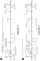
- FIG. 2 and FIG. 3 are graphical illustrations of the manner in which the controller 140 causes the vehicle 100 to operate when the HEV and SEV driving modes are selected, respectively.
- the figures show state of charge of the charge storage module 150 along a horizontal axis. The content of the figures will now be discussed.
- the controller 140 is configured to implement the following measures:
- the controller 140 forces the powertrain to assume the parallel recharge mode until the SoC of the charge storage module 150 exceeds a prescribed minimum engine stop SoC value.
- the powertrain 131 may resume operation in the EV mode if the controller 140 determines this is the optimum mode according to the energy optimisation strategy. If the powertrain 131 resumes operation in the EV mode once the SoC exceeds the prescribed minimum engine stop SoC value following an engine start due to the SoC falling below the engine start SoC value, the minimum engine stop SoC value is incremented by a prescribed increment amount.
- the prescribed increment amount is higher when operating in SEV mode compared with HEV mode although in some embodiments the increment amounts may be substantially equal. This feature has the effect that when the engine 121 is next started, it must charge the energy storage module 150 to a higher SoC before the engine 121 may be switched off, increasing the available charge for operation in EV mode.
- the prescribed increment amount when operating in HEV mode the prescribed increment amount is 2% each time the engine is stopped as soon as the SoC reaches the minimum engine stop SoC value.
- the prescribed increment amount when operating in SEV mode the prescribed increment amount is 3%. Other values are also useful.
- the minimum engine stop SoC is higher when operating in the SEV mode compared with the HEV mode. This allows longer uninterrupted periods of operation in EV mode in a number of situations.
- the minimum engine stop SoC is around 43% when operating in HEV mode and around 44.5% when operating in SEV mode. Other values are also useful.
- This feature has the advantage that a time period for which the powertrain 131 operates in EV mode may be increased.
- the controller 140 When the powertrain 131 is operated in a parallel mode, the controller 140 is operable to assume the parallel torque boost mode when an amount of driver torque demand exceeds that which may be provided by the engine 121 alone at its maximum torque output. As noted above, driver torque demand is related to accelerator pedal position. In the SEV mode, the controller 140 limits provision of torque boost to situations in which the accelerator pedal is depressed more than a prescribed amount (which may be specified in terms of a proportion of full travel in some embodiments). In the present embodiment, when the vehicle is operated in the SEV mode the parallel torque boost mode is only permitted when the accelerator pedal 171 is depressed by more than 95%, corresponding to movement of the pedal 171 beyond the 'kick down' detent in the present embodiment. Other arrangements are also useful. However, this feature advantageously reduces draining of charge from charge storage module 150 relative to operation in the HEV hybrid operating mode.
- controller 140 may suspend provision of torque boost in the SEV mode altogether.
- torque filling is also restricted when in the SEV mode compared with the HEV mode. In some embodiments torque filling is not permitted in the SEV mode.
- energy overrun charging i.e. use of the engine to drive the CIMG 123C in order to slow the vehicle when the engine 121 is switched on
- HEV mode is not permitted in the HEV mode, but is permitted in the SEV mode.
- Other arrangements are also useful.
- controller 140 is configured to store computer program code for causing one or more computing devices of the controller 140 to perform the method of vehicle control described herein. It is to be understood that a controller according to an embodiment of the present invention may be provided by a plurality of computing devices. The functionality described as being performed by the controller may be performed by a plurality of computing devices, control modules or the like, optionally at different physical locations of a vehicle.
Landscapes
- Engineering & Computer Science (AREA)
- Transportation (AREA)
- Mechanical Engineering (AREA)
- Automation & Control Theory (AREA)
- Chemical & Material Sciences (AREA)
- Combustion & Propulsion (AREA)
- Human Computer Interaction (AREA)
- Electric Propulsion And Braking For Vehicles (AREA)
- Hybrid Electric Vehicles (AREA)
- Control Of Electric Motors In General (AREA)
Claims (14)
- Steuerung (140) für ein Hybrid-Elektrofahrzeug (100) mit einem Antriebsstrang, wobei der Antriebsstrang einen Motor (121), elektrische Antriebsmittel, die von Energiespeicherungsmitteln (150) angetrieben werden, und elektrische Generatormittel einschließt, die betreibbar sind, um von dem Motor (121) angetrieben zu werden, um das Energiespeicherungsmittel (150) aufzuladen, wobei die Steuerung (140) betreibbar ist zum:Empfangen eines Signals, das einen erforderlichen Hybrid-Betriebsmodus des Fahrzeugs (100) anzeigt, wobei die Hybrid-Betriebsmodi einen ersten Hybrid-Betriebsmodus, der einen verlängerten Betrieb in einem Elektrofahrzeug (EV)-Antriebsstrangmodus begünstigt, indem das Laden der Energiespeicherungsmittel gefördert wird, und einen zweiten Hybrid-Betriebsmodus, der eine Reduktion des Kraftstoffverbrauchs begünstigt, umfassen, wobei in jedem Hybrid-Betriebsmodus der Antriebsstrang konfiguriert ist, um in einer Vielzahl von verschiedenen Antriebsstrangmodi zu arbeiten;Empfangen eines Signals, das einen Ladezustand der Energiespeicherungsmittel (150) anzeigt;Bestimmen, welcher der Vielzahl von Antriebsstrangmodi für den Fahrzeugbetrieb zu einem gegebenen Zeitpunkt geeignet ist, wobei die Antriebsstrangmodi einen Motorauflade-Antriebsstrangmodus einschließen, in dem der Motor (121) die Generatormittel antreibt, um die Energiespeicherungsmittel (150) aufzuladen, und den Elektrofahrzeug (Elektrofahrzeug)-Antriebsstrangmodus, in dem der Motor (121) abgeschaltet ist und die elektrischen Antriebsmittel betreibbar sind, um ein Antriebsdrehmoment zum Antreiben des Fahrzeugs (100) zu entwickeln; undBewirken, dass der Antriebsstrang den geeigneten Antriebsstrangmodus annimmt, wobei die Steuerung (140) betreibbar ist, um zu bestimmen, welcher aus der Vielzahl der Antriebsstrangmodi für den Fahrzeugbetrieb geeignet ist, zumindest teilweise in Abhängigkeit von dem Signal, das den momentanen Betriebszustand der Energiespeicherungsmittel (150) anzeigt, und einem Referenzwert des Ladezustands, wobei der Referenzwert in dem ersten Hybrid-Betriebsmodus höher ist als derjenige in dem zweiten Hybrid-Betriebsmodus, und die Steuerung (140) betreibbar ist, um den Referenzwert des Betriebszustands auf einen von einer Vielzahl von verschiedenen jeweiligen Werten in Abhängigkeit von dem Signal, das den erforderlichen Hybrid-Betriebsmodus anzeigt, einzustellen;wobei die Steuerung betreibbar ist, um zu bestimmen, welcher der Antriebsstrangmodi zu einem gegebenen Zeitpunkt gemäß einem Wert einer Kostenfunktion für jeden Antriebsstrangmodus geeignet ist, wobei der Wert der Kostenfunktion zumindest teilweise durch Bezugnahme auf das Signal, das den momentanen Ladezustand anzeigt, und den Referenzwert des Ladezustands der jeweiligen Antriebsstrangmodi bestimmt wird.
- Steuerung (140) nach Anspruch 1, die betreibbar ist, um den geeigneten Antriebsstrangmodi in Abhängigkeit zumindest teilweise von einer Abweichung des den momentanen Betriebszustand anzeigenden Signals vom Referenzwert des Betriebszustands zu bestimmen.
- Steuerung (140) nach Anspruch 1 oder Anspruch 2, wobei der Wert der Kostenfunktion jedes Antriebsstrangmodi zumindest teilweise in weiterer Abhängigkeit von mindestens einem aus einer Rate des Kraftstoffverbrauchs des Fahrzeugs, einer Rate der Emission eines Gases durch das Fahrzeug und einer durch das Fahrzeug erzeugten Geräuschmenge bestimmt wird, wobei die Steuerung optional konfiguriert ist, um den erforderlichen Antriebsstrangmodi gemäß einer Feedback-Stackelberg-Gleichgewichtssteuerungs-Optimierungsmethodik zu bestimmen.
- Steuerung (140) nach einem der vorstehenden Ansprüche, die eingerichtet ist, um von einem Benutzer ein Signal zu empfangen, das den erforderlichen Hybrid-Betriebsmodus anzeigt.
- Steuerung (140) nach einem der vorstehenden Ansprüche, wobei, wenn sich der Antriebsstrang im Elektrofahrzeug-Antriebsstrangmodus befindet, die Steuerung betreibbar ist, um zu bewirken, dass der Antriebsstrang den Motorauflade-Antriebsstrangmodus zumindest teilweise in Abhängigkeit von der Drehmomentanforderung des Fahrers annimmt, wobei, wenn der erste Hybrid-Betriebsmodus ausgewählt ist, die Steuerung konfiguriert ist, um zu bewirken, dass das Fahrzeug den Motorauflade-Antriebsstrangmodus nur bei höheren Werten der Drehmomentanforderung des Fahrers annimmt, als wenn der zweite Hybrid-Betriebsmodus ausgewählt ist.
- Steuerung (140) nach einem der vorstehenden Ansprüche, wobei, wenn sich der Antriebsstrang im Motorauflade-Betriebsmodus befindet, die Steuerung konfiguriert ist, um zu bewirken, dass die Generatormittel eine größere Ladelast auf den Motor (121) aufbringen, wenn sich das Fahrzeug (100) im ersten Hybrid-Betriebsmodus befindet, verglichen mit dem zweiten Hybrid-Betriebsmodus.
- Steuerung (140) nach einem der vorstehenden Ansprüche, wobei die Steuerung (140) betreibbar ist, um zu bewirken, dass der Motor (121) eingeschaltet wird, wenn die Fahrzeuggeschwindigkeit einen vorgeschriebenen Wert überschreitet, wobei der vorgeschriebene Wert höher ist, wenn das Fahrzeug in dem ersten Hybrid-Betriebsmodus relativ zu dem zweiten Hybrid-Betriebsmodus betrieben wird.
- Steuerung (140) nach Anspruch 7, wobei, wenn die Steuerung (140) das Fahrzeug (100) veranlasst, in dem ersten Hybrid-Betriebsmodus oder dem zweiten Hybrid-Betriebsmodus zu arbeiten, die Steuerung (140) eingerichtet ist, um zu bewirken, dass der Motor (121) zumindest teilweise in Abhängigkeit von einem Betrag, um den ein Gaspedal (171) niedergedrückt wird, eingeschaltet wird.
- Steuerung (140) nach einem der vorstehenden Ansprüche, wobei der Ladezustand des Energiespeicherungsmittels (150) nur dann einen Wert von einem vorgeschriebenen absoluten minimalen Betriebszustand bis zu einem vorgeschriebenen weichen Minimalwert annehmen darf, der größer als der vorgeschriebene absolute minimale Betriebszustand ist, wenn das Fahrzeug in dem ersten Hybrid-Betriebsmodus oder bei der Fahrzeuginitialisierung betrieben wird, wobei optional die Größe des Intervalls von dem vorgeschriebenen absoluten minimalen Betriebszustand bis zu dem vorgeschriebenen weichen Minimalwert etwa 10 % der Größe des Intervalls von dem vorgeschriebenen absoluten minimalen Betriebszustand bis zu einem vorgeschriebenen absoluten maximalen Betriebszustand beträgt.
- Steuerung (140) nach einem der vorstehenden Ansprüche, die betreibbar ist, um zu bewirken, dass der Motor (121) antriebsmäßig mit einem oder mehreren Rädern des Fahrzeugs (100) zusätzlich zu den elektrischen Antriebsmitteln gekoppelt wird, die optional betreibbar sind, um zu bewirken, dass der Motor (121) ein Antriebsdrehmoment liefert, wenn der Antriebsstrang im Motorauflade-Antriebsstrangmodus betrieben wird, die optional betreibbar sind, um zu bewirken, dass der Antriebsstrang in einem Parallelmodus arbeitet, in dem der Motor (121) ein Antriebsdrehmoment an ein oder mehrere Räder zusätzlich zu den elektrischen Antriebsmitteln liefert.
- Hybrid-Elektrofahrzeug-Antriebsstrang (131), umfassend einen Motor (121), elektrische Antriebsmittel, die von Energiespeicherungsmitteln (150) angetrieben werden, und elektrische Generatormittel, die betreibbar sind, um von dem Motor angetrieben zu werden, um die Energiespeicherungsmittel (150) aufzuladen, und eine Steuerung (140) nach
einem der vorstehenden Ansprüche, wobei die elektrischen Generatormittel und die elektrischen Antriebsmittel jeweils durch eine elektrische Maschine bereitgestellt sind und wobei die Steuerung betreibbar ist, um zu bewirken, dass die elektrische Maschine als ein Antriebsmotor oder als ein Generator betrieben wird, wobei optional die Generatormittel einen elektrischen Generator umfassen und die elektrischen Antriebsmittel einen Antriebsmotor umfassen, wobei der Generator und der Motor durch jeweils unterschiedliche elektrische Maschinen bereitgestellt sind. - Hybrid-Elektrofahrzeug (100), umfassend
einen Antriebsstrang (131) nach Anspruch 11, der optional in einem Parallelmodus betreibbar ist, in dem der Motor (121) ein Antriebsdrehmoment an den Antriebsstrang liefert, optional in einem Serienmodus betreibbar ist, in dem der Motor (121) die Generatormittel antreibt, um Ladung zu entwickeln, um die Batterie aufzuladen oder den Antriebsmotor anzutreiben, während der Antriebsmotor ein Antriebsdrehmoment an den Antriebsstrang liefert. - Verfahren zum Steuern eines Hybrid-Elektrofahrzeugs (100) mit einem Antriebsstrang, wobei der Antriebsstrang einen Motor (121), elektrische Antriebsmittel, die von Energiespeicherungsmitteln (150) angetrieben werden, und elektrische Generatormittel umfasst, die betreibbar sind, um von dem Motor angetrieben zu werden, um die Energiespeicherungsmittel (150) aufzuladen, wobei das Verfahren umfasst:Empfangen eines Signals, das einen erforderlichen Hybrid-Betriebsmodus anzeigt, wobei die Hybrid-Betriebsmodi einen ersten Hybrid-Betriebsmodus, der einen verlängerten Betrieb in einem Elektrofahrzeug-Antriebsstrangmodus (EV-Antriebsstrangmodus) begünstigt, indem das Laden der Energiespeicherungsmittel gefördert wird, und einen zweiten Hybrid-Betriebsmodus, der eine Reduktion des Kraftstoffverbrauchs begünstigt, umfassen, wobei in jedem Hybrid-Betriebsmodus der Antriebsstrang konfiguriert ist, um in einer Vielzahl von verschiedenen Antriebsstrangmodi zu arbeiten;Empfangen eines Signals, das einen Ladezustand der Energiespeicherungsmittel (150) anzeigt;Bestimmen, welcher aus einer Vielzahl von Antriebsstrangmodi für den Fahrzeugbetrieb zu einem gegebenen Zeitpunkt geeignet ist, wobei die Antriebsstrangmodi einen Motorauflade-Antriebsstrangmodus einschließen, in dem der Motor (121) das Generatormittel antreibt, um das Energiespeicherungsmittel (150) aufzuladen, und den Elektrofahrzeug (Elektrofahrzeug)-Antriebsstrangmodus, in dem der Motor (121) abgeschaltet ist und das elektrische Antriebsmittel betreibbar ist, um ein Antriebsdrehmoment zu entwickeln, um das Fahrzeug anzutreiben; undBewirken, dass der Antriebsstrang den geeigneten Antriebsstrangmodi annimmt,wobei das Verfahren das Bestimmen umfasst, welcher aus der Vielzahl von Antriebsstrang-Betriebsmodi für den Fahrzeugbetrieb geeignet ist, zumindest teilweise in Abhängigkeit von dem Signal, das den momentanen Betriebszustand der Energiespeicherungsmittel (150) anzeigt, und einem Referenzwert des Ladezustands, wobei der Referenzwert in dem ersten Hybrid-Betriebsmodus höher ist als der in dem zweiten Hybrid-Betriebsmodus, und das Einstellen des Referenzwerts des Ladezustands auf einen aus einer Vielzahl von verschiedenen jeweiligen Werten in Abhängigkeit von dem Signal, das den erforderlichen Hybrid-Betriebsmodus anzeigt;wobei das Verfahren das Bestimmen umfasst, welcher der Antriebsstrangmodi zu einem gegebenen Zeitpunkt gemäß einem Wert einer Kostenfunktion für jeden Antriebsstrangmodus geeignet ist, wobei der Wert der Kostenfunktion zumindest teilweise durch Bezugnahme auf das Signal, das den momentanen Ladezustand anzeigt, und den Referenzwert des Ladezustands der jeweiligen Antriebsstrangmodi bestimmt wird.
- Computerlesbares Medium, das Computerprogrammcode zur Durchführung des Verfahrens nach Anspruch 13 enthält.
Applications Claiming Priority (2)
| Application Number | Priority Date | Filing Date | Title |
|---|---|---|---|
| GB1314990.1A GB2517470B (en) | 2013-08-21 | 2013-08-21 | Hybrid electric vehicle controller and method |
| PCT/EP2014/067752 WO2015024971A2 (en) | 2013-08-21 | 2014-08-20 | Hybrid electric vehicle controller and method |
Publications (2)
| Publication Number | Publication Date |
|---|---|
| EP3036121A2 EP3036121A2 (de) | 2016-06-29 |
| EP3036121B1 true EP3036121B1 (de) | 2024-10-30 |
Family
ID=49302033
Family Applications (1)
| Application Number | Title | Priority Date | Filing Date |
|---|---|---|---|
| EP14752888.9A Active EP3036121B1 (de) | 2013-08-21 | 2014-08-20 | Steuerung für elektrisches hybridfahrzeug und verfahren |
Country Status (6)
| Country | Link |
|---|---|
| US (2) | US10053081B2 (de) |
| EP (1) | EP3036121B1 (de) |
| JP (2) | JP2016533951A (de) |
| CN (1) | CN105473407B (de) |
| GB (2) | GB2517470B (de) |
| WO (1) | WO2015024971A2 (de) |
Families Citing this family (26)
| Publication number | Priority date | Publication date | Assignee | Title |
|---|---|---|---|---|
| KR101573633B1 (ko) * | 2014-09-30 | 2015-12-01 | 현대자동차주식회사 | 하이브리드의 변속기 구조 및 모드 변환 방법 |
| GB2545733B (en) * | 2015-12-23 | 2019-04-17 | Protean Electric Ltd | A control system for a vehicle |
| FR3050709B1 (fr) * | 2016-05-02 | 2020-03-27 | Peugeot Citroen Automobiles Sa | Procede de pilotage d'une machine electrique d'un groupe motopropulseur hybride en fonction de la consigne conducteur |
| US10235818B2 (en) * | 2016-05-13 | 2019-03-19 | Ford Global Technologies, Llc | Adaptive vehicle control |
| JP6443694B2 (ja) * | 2016-09-07 | 2018-12-26 | トヨタ自動車株式会社 | 車両の走行制御装置 |
| JP2018131040A (ja) * | 2017-02-15 | 2018-08-23 | 株式会社Subaru | 車両用制御装置 |
| KR101876740B1 (ko) * | 2017-04-17 | 2018-07-10 | 현대자동차주식회사 | 하이브리드 자동차 및 그를 모드 전환 방법 |
| US10618512B2 (en) * | 2017-08-04 | 2020-04-14 | Toyota Motor Engineering & Manufacturing North America, Inc. | Expanding electric vehicle mode during downhill grade conditions |
| KR102422138B1 (ko) * | 2017-11-01 | 2022-07-18 | 현대자동차주식회사 | 하이브리드 자동차 및 그를 위한 엔진 기동 제어 방법 |
| JP7373805B2 (ja) * | 2018-10-31 | 2023-11-06 | パナソニックIpマネジメント株式会社 | 情報処理システム、制御装置、及び車両用電源システム |
| JP7287017B2 (ja) * | 2019-03-14 | 2023-06-06 | 株式会社デンソー | 移動体用電源システム |
| CN109910619B (zh) * | 2019-03-29 | 2022-03-15 | 南京汽车集团有限公司 | 一种新能源汽车整车电控策略开发方法 |
| CN112810599B (zh) * | 2020-04-17 | 2022-04-12 | 长城汽车股份有限公司 | 车辆驱动控制方法、系统 |
| EP4015327A1 (de) * | 2020-12-17 | 2022-06-22 | Volvo Car Corporation | Verfahren zum bremsen eines hybrid-elektrofahrzeugs |
| CN114728654A (zh) * | 2021-07-19 | 2022-07-08 | 华为数字能源技术有限公司 | 一种混合动力车辆驱动控制方法及系统 |
| US12319160B1 (en) | 2021-08-13 | 2025-06-03 | Oshkosh Defense, Llc | Convoy operations for electrified military vehicles |
| US12583309B1 (en) | 2021-08-13 | 2026-03-24 | Oshkosh Defense, Llc | Hybrid power system for a military vehicle |
| US12130122B1 (en) | 2021-08-13 | 2024-10-29 | Oshkosh Defense, Llc | Military vehicle with battery armor |
| US12351028B1 (en) | 2021-08-13 | 2025-07-08 | Oshkosh Defense, Llc | Military vehicle with modular battery units |
| US11485228B1 (en) | 2021-08-13 | 2022-11-01 | Oshkosh Defense, Llc | Electrified military vehicle |
| US12083995B1 (en) | 2021-08-13 | 2024-09-10 | Oshkosh Defense, Llc | Power export system for a military vehicle |
| US11498409B1 (en) | 2021-08-13 | 2022-11-15 | Oshkosh Defense, Llc | Electrified military vehicle |
| US12060053B1 (en) | 2021-08-13 | 2024-08-13 | Oshkosh Defense, Llc | Military vehicle with control modes |
| US12358361B1 (en) | 2021-08-13 | 2025-07-15 | Oshkosh Defense, Llc | Electrified military vehicle with electric weaponry support system |
| US12311754B1 (en) | 2021-08-13 | 2025-05-27 | Oshkosh Defense, Llc | Power export system for a military vehicle |
| CN117227514B (zh) * | 2023-11-16 | 2024-01-19 | 太原科技大学 | 增程式电动汽车能量管理的方法、系统及存储介质 |
Citations (2)
| Publication number | Priority date | Publication date | Assignee | Title |
|---|---|---|---|---|
| EP1920986A1 (de) * | 2005-09-01 | 2008-05-14 | Toyota Jidosha Kabushiki Kaisha | Hybridfahrzeug und steuerverfahren dafür |
| JP2012106672A (ja) * | 2010-11-18 | 2012-06-07 | Toyota Motor Corp | ハイブリッド自動車 |
Family Cites Families (25)
| Publication number | Priority date | Publication date | Assignee | Title |
|---|---|---|---|---|
| JP3013764B2 (ja) * | 1995-10-03 | 2000-02-28 | 三菱自動車工業株式会社 | ハイブリッド電気自動車の充放電制御装置 |
| JPH09233607A (ja) * | 1996-02-29 | 1997-09-05 | Toyota Motor Corp | ハイブリッド車両の駆動制御装置 |
| JP3767103B2 (ja) * | 1997-07-16 | 2006-04-19 | 日産自動車株式会社 | 電気自動車の制御装置 |
| JP2002051405A (ja) * | 2000-07-31 | 2002-02-15 | Sanyo Electric Co Ltd | ハイブリッド電気自動車 |
| US6941198B2 (en) * | 2003-09-10 | 2005-09-06 | Ford Motor Company | Method for controlling activation of a power source of a hybrid electric vehicle |
| JP4341704B2 (ja) | 2007-07-12 | 2009-10-07 | トヨタ自動車株式会社 | ハイブリッド車両およびハイブリッド車両の制御方法 |
| JP4513882B2 (ja) * | 2008-03-21 | 2010-07-28 | トヨタ自動車株式会社 | ハイブリッド車およびその制御方法 |
| JP4466772B2 (ja) * | 2008-09-03 | 2010-05-26 | トヨタ自動車株式会社 | 車両の制御装置 |
| JP2009143563A (ja) * | 2009-01-26 | 2009-07-02 | Toyota Motor Corp | ハイブリッド車両 |
| JP2011057117A (ja) | 2009-09-11 | 2011-03-24 | Toyota Motor Corp | ハイブリッド車 |
| US9764632B2 (en) * | 2010-01-07 | 2017-09-19 | Ford Global Technologies, Llc | Plug-in hybrid electric vehicle battery state of charge hold function and energy management |
| CN102858576B (zh) * | 2010-04-14 | 2015-08-19 | 丰田自动车株式会社 | 混合动力车辆 |
| DE102010022018B4 (de) * | 2010-05-29 | 2012-08-23 | Audi Ag | Verfahren zum Betreiben eines Fahrzeugs mit Verbrennungskraftmaschine und Generator |
| JP5093300B2 (ja) * | 2010-06-15 | 2012-12-12 | トヨタ自動車株式会社 | 車両制御システム |
| JP5552944B2 (ja) * | 2010-07-29 | 2014-07-16 | 三菱自動車工業株式会社 | ハイブリッド車両の制御装置 |
| US20130218386A1 (en) * | 2010-08-04 | 2013-08-22 | Fisker Automotive, Inc. | Vehicle operation mode systems and methods |
| GB201014680D0 (en) * | 2010-09-04 | 2010-10-20 | Jaguar Cars | Controller and method of control of a hybrid electric vehicle |
| CN103079860B (zh) * | 2010-09-10 | 2017-02-15 | 艾里逊变速箱公司 | 混合系统 |
| GB2486709B (en) | 2010-12-23 | 2017-10-11 | Jaguar Land Rover Ltd | Hybrid electric vehicle controller and method of controlling a hybrid electric vehicle |
| US8447451B2 (en) * | 2011-04-22 | 2013-05-21 | GM Global Technology Operations LLC | System and method for controlling operation of an electric all-wheel drive hybrid vehicle |
| WO2013021450A1 (ja) * | 2011-08-08 | 2013-02-14 | トヨタ自動車株式会社 | ハイブリッド車における車両状態表示装置 |
| JP5854315B2 (ja) * | 2011-09-14 | 2016-02-09 | 日産自動車株式会社 | ハイブリッド車両の制御装置 |
| WO2013059667A1 (en) * | 2011-10-21 | 2013-04-25 | Fisker Automotive, Inc. | Systems and methods for controlling operation of a vehicle |
| JP5712915B2 (ja) | 2011-12-21 | 2015-05-07 | トヨタ自動車株式会社 | プラグインハイブリッド車両 |
| JP2013147193A (ja) * | 2012-01-20 | 2013-08-01 | Toyota Motor Corp | ハイブリッド車両用駆動装置 |
-
2013
- 2013-08-21 GB GB1314990.1A patent/GB2517470B/en active Active
-
2014
- 2014-08-20 CN CN201480045864.3A patent/CN105473407B/zh active Active
- 2014-08-20 EP EP14752888.9A patent/EP3036121B1/de active Active
- 2014-08-20 GB GB1414794.6A patent/GB2519841B/en active Active
- 2014-08-20 WO PCT/EP2014/067752 patent/WO2015024971A2/en not_active Ceased
- 2014-08-20 JP JP2016535471A patent/JP2016533951A/ja active Pending
- 2014-08-20 US US14/910,814 patent/US10053081B2/en active Active
-
2018
- 2018-03-26 JP JP2018058464A patent/JP2018150038A/ja active Pending
- 2018-07-17 US US16/037,792 patent/US20180326970A1/en not_active Abandoned
Patent Citations (2)
| Publication number | Priority date | Publication date | Assignee | Title |
|---|---|---|---|---|
| EP1920986A1 (de) * | 2005-09-01 | 2008-05-14 | Toyota Jidosha Kabushiki Kaisha | Hybridfahrzeug und steuerverfahren dafür |
| JP2012106672A (ja) * | 2010-11-18 | 2012-06-07 | Toyota Motor Corp | ハイブリッド自動車 |
Also Published As
| Publication number | Publication date |
|---|---|
| CN105473407A (zh) | 2016-04-06 |
| US10053081B2 (en) | 2018-08-21 |
| GB201314990D0 (en) | 2013-10-02 |
| CN105473407B (zh) | 2019-05-03 |
| JP2016533951A (ja) | 2016-11-04 |
| GB2517470B (en) | 2016-07-20 |
| GB2517470A (en) | 2015-02-25 |
| US20180326970A1 (en) | 2018-11-15 |
| JP2018150038A (ja) | 2018-09-27 |
| GB2519841A (en) | 2015-05-06 |
| GB201414794D0 (en) | 2014-10-01 |
| WO2015024971A2 (en) | 2015-02-26 |
| GB2519841B (en) | 2017-05-24 |
| WO2015024971A3 (en) | 2015-07-30 |
| US20160193992A1 (en) | 2016-07-07 |
| EP3036121A2 (de) | 2016-06-29 |
Similar Documents
| Publication | Publication Date | Title |
|---|---|---|
| EP3036121B1 (de) | Steuerung für elektrisches hybridfahrzeug und verfahren | |
| EP3036119B1 (de) | Steuerung für elektrisches hybridfahrzeug und verfahren | |
| JP4988046B1 (ja) | 回生制御装置、ハイブリッド自動車および回生制御方法、並びにプログラム | |
| RU2705867C1 (ru) | Система управления приводом гибридного транспортного средства | |
| CN104816638B (zh) | 车辆 | |
| KR101481288B1 (ko) | 하이브리드차량의 운전제어방법 | |
| KR20180083395A (ko) | 하이브리드 자동차의 구동 장치 제어 방법, 그리고 하이브리드 자동차 | |
| CN101687508A (zh) | 车辆行驶控制装置以及车辆行驶控制方法 | |
| GB2486709A (en) | Hybrid electric vehicle controller which selects power source at vehicle start-up | |
| US20190054913A1 (en) | Vehicle control system and method | |
| RU2013119394A (ru) | Экономичная система круиз-контроля | |
| CN104691541A (zh) | 具有三种模式耗尽策略的混合动力传动系及其操作方法 | |
| JP2015154534A (ja) | 蓄電池制御装置 | |
| JP7235173B2 (ja) | ハイブリッド車の制御装置 | |
| JP2018100013A (ja) | ハイブリッド車両 | |
| CN109367385A (zh) | 一种混合动力汽车及其控制方法 | |
| JP2022084429A (ja) | ハイブリッド車両の制御装置 | |
| JP2003130199A (ja) | 有段変速機を備えたハイブリッド車両 | |
| JP5764934B2 (ja) | パラレル式ハイブリッド車両走行制御装置 | |
| WO2022202025A1 (ja) | 車両の走行制御装置 | |
| US20160068168A1 (en) | Electrified vehicle operating mode prompt | |
| JP6773547B2 (ja) | ハイブリッド自動車の制御装置 |
Legal Events
| Date | Code | Title | Description |
|---|---|---|---|
| PUAI | Public reference made under article 153(3) epc to a published international application that has entered the european phase |
Free format text: ORIGINAL CODE: 0009012 |
|
| 17P | Request for examination filed |
Effective date: 20160321 |
|
| AK | Designated contracting states |
Kind code of ref document: A2 Designated state(s): AL AT BE BG CH CY CZ DE DK EE ES FI FR GB GR HR HU IE IS IT LI LT LU LV MC MK MT NL NO PL PT RO RS SE SI SK SM TR |
|
| AX | Request for extension of the european patent |
Extension state: BA ME |
|
| DAX | Request for extension of the european patent (deleted) | ||
| STAA | Information on the status of an ep patent application or granted ep patent |
Free format text: STATUS: EXAMINATION IS IN PROGRESS |
|
| 17Q | First examination report despatched |
Effective date: 20190301 |
|
| P01 | Opt-out of the competence of the unified patent court (upc) registered |
Effective date: 20230528 |
|
| GRAP | Despatch of communication of intention to grant a patent |
Free format text: ORIGINAL CODE: EPIDOSNIGR1 |
|
| STAA | Information on the status of an ep patent application or granted ep patent |
Free format text: STATUS: GRANT OF PATENT IS INTENDED |
|
| INTG | Intention to grant announced |
Effective date: 20240522 |
|
| GRAS | Grant fee paid |
Free format text: ORIGINAL CODE: EPIDOSNIGR3 |
|
| GRAA | (expected) grant |
Free format text: ORIGINAL CODE: 0009210 |
|
| STAA | Information on the status of an ep patent application or granted ep patent |
Free format text: STATUS: THE PATENT HAS BEEN GRANTED |
|
| AK | Designated contracting states |
Kind code of ref document: B1 Designated state(s): AL AT BE BG CH CY CZ DE DK EE ES FI FR GB GR HR HU IE IS IT LI LT LU LV MC MK MT NL NO PL PT RO RS SE SI SK SM TR |
|
| REG | Reference to a national code |
Ref country code: GB Ref legal event code: FG4D |
|
| REG | Reference to a national code |
Ref country code: CH Ref legal event code: EP |
|
| REG | Reference to a national code |
Ref country code: IE Ref legal event code: FG4D |
|
| REG | Reference to a national code |
Ref country code: DE Ref legal event code: R096 Ref document number: 602014091082 Country of ref document: DE |
|
| REG | Reference to a national code |
Ref country code: LT Ref legal event code: MG9D |
|
| REG | Reference to a national code |
Ref country code: NL Ref legal event code: MP Effective date: 20241030 |
|
| PG25 | Lapsed in a contracting state [announced via postgrant information from national office to epo] |
Ref country code: IS Free format text: LAPSE BECAUSE OF FAILURE TO SUBMIT A TRANSLATION OF THE DESCRIPTION OR TO PAY THE FEE WITHIN THE PRESCRIBED TIME-LIMIT Effective date: 20250228 Ref country code: PT Free format text: LAPSE BECAUSE OF FAILURE TO SUBMIT A TRANSLATION OF THE DESCRIPTION OR TO PAY THE FEE WITHIN THE PRESCRIBED TIME-LIMIT Effective date: 20250228 Ref country code: HR Free format text: LAPSE BECAUSE OF FAILURE TO SUBMIT A TRANSLATION OF THE DESCRIPTION OR TO PAY THE FEE WITHIN THE PRESCRIBED TIME-LIMIT Effective date: 20241030 |
|
| PG25 | Lapsed in a contracting state [announced via postgrant information from national office to epo] |
Ref country code: FI Free format text: LAPSE BECAUSE OF FAILURE TO SUBMIT A TRANSLATION OF THE DESCRIPTION OR TO PAY THE FEE WITHIN THE PRESCRIBED TIME-LIMIT Effective date: 20241030 Ref country code: NL Free format text: LAPSE BECAUSE OF FAILURE TO SUBMIT A TRANSLATION OF THE DESCRIPTION OR TO PAY THE FEE WITHIN THE PRESCRIBED TIME-LIMIT Effective date: 20241030 |
|
| REG | Reference to a national code |
Ref country code: AT Ref legal event code: MK05 Ref document number: 1736578 Country of ref document: AT Kind code of ref document: T Effective date: 20241030 |
|
| PG25 | Lapsed in a contracting state [announced via postgrant information from national office to epo] |
Ref country code: BG Free format text: LAPSE BECAUSE OF FAILURE TO SUBMIT A TRANSLATION OF THE DESCRIPTION OR TO PAY THE FEE WITHIN THE PRESCRIBED TIME-LIMIT Effective date: 20241030 |
|
| PG25 | Lapsed in a contracting state [announced via postgrant information from national office to epo] |
Ref country code: ES Free format text: LAPSE BECAUSE OF FAILURE TO SUBMIT A TRANSLATION OF THE DESCRIPTION OR TO PAY THE FEE WITHIN THE PRESCRIBED TIME-LIMIT Effective date: 20241030 |
|
| PG25 | Lapsed in a contracting state [announced via postgrant information from national office to epo] |
Ref country code: NO Free format text: LAPSE BECAUSE OF FAILURE TO SUBMIT A TRANSLATION OF THE DESCRIPTION OR TO PAY THE FEE WITHIN THE PRESCRIBED TIME-LIMIT Effective date: 20250130 |
|
| PG25 | Lapsed in a contracting state [announced via postgrant information from national office to epo] |
Ref country code: LV Free format text: LAPSE BECAUSE OF FAILURE TO SUBMIT A TRANSLATION OF THE DESCRIPTION OR TO PAY THE FEE WITHIN THE PRESCRIBED TIME-LIMIT Effective date: 20241030 Ref country code: AT Free format text: LAPSE BECAUSE OF FAILURE TO SUBMIT A TRANSLATION OF THE DESCRIPTION OR TO PAY THE FEE WITHIN THE PRESCRIBED TIME-LIMIT Effective date: 20241030 Ref country code: GR Free format text: LAPSE BECAUSE OF FAILURE TO SUBMIT A TRANSLATION OF THE DESCRIPTION OR TO PAY THE FEE WITHIN THE PRESCRIBED TIME-LIMIT Effective date: 20250131 |
|
| PG25 | Lapsed in a contracting state [announced via postgrant information from national office to epo] |
Ref country code: PL Free format text: LAPSE BECAUSE OF FAILURE TO SUBMIT A TRANSLATION OF THE DESCRIPTION OR TO PAY THE FEE WITHIN THE PRESCRIBED TIME-LIMIT Effective date: 20241030 |
|
| PG25 | Lapsed in a contracting state [announced via postgrant information from national office to epo] |
Ref country code: RS Free format text: LAPSE BECAUSE OF FAILURE TO SUBMIT A TRANSLATION OF THE DESCRIPTION OR TO PAY THE FEE WITHIN THE PRESCRIBED TIME-LIMIT Effective date: 20250130 |
|
| PG25 | Lapsed in a contracting state [announced via postgrant information from national office to epo] |
Ref country code: SM Free format text: LAPSE BECAUSE OF FAILURE TO SUBMIT A TRANSLATION OF THE DESCRIPTION OR TO PAY THE FEE WITHIN THE PRESCRIBED TIME-LIMIT Effective date: 20241030 |
|
| PG25 | Lapsed in a contracting state [announced via postgrant information from national office to epo] |
Ref country code: DK Free format text: LAPSE BECAUSE OF FAILURE TO SUBMIT A TRANSLATION OF THE DESCRIPTION OR TO PAY THE FEE WITHIN THE PRESCRIBED TIME-LIMIT Effective date: 20241030 |
|
| PG25 | Lapsed in a contracting state [announced via postgrant information from national office to epo] |
Ref country code: EE Free format text: LAPSE BECAUSE OF FAILURE TO SUBMIT A TRANSLATION OF THE DESCRIPTION OR TO PAY THE FEE WITHIN THE PRESCRIBED TIME-LIMIT Effective date: 20241030 |
|
| PG25 | Lapsed in a contracting state [announced via postgrant information from national office to epo] |
Ref country code: RO Free format text: LAPSE BECAUSE OF FAILURE TO SUBMIT A TRANSLATION OF THE DESCRIPTION OR TO PAY THE FEE WITHIN THE PRESCRIBED TIME-LIMIT Effective date: 20241030 |
|
| PG25 | Lapsed in a contracting state [announced via postgrant information from national office to epo] |
Ref country code: SK Free format text: LAPSE BECAUSE OF FAILURE TO SUBMIT A TRANSLATION OF THE DESCRIPTION OR TO PAY THE FEE WITHIN THE PRESCRIBED TIME-LIMIT Effective date: 20241030 |
|
| PG25 | Lapsed in a contracting state [announced via postgrant information from national office to epo] |
Ref country code: CZ Free format text: LAPSE BECAUSE OF FAILURE TO SUBMIT A TRANSLATION OF THE DESCRIPTION OR TO PAY THE FEE WITHIN THE PRESCRIBED TIME-LIMIT Effective date: 20241030 |
|
| PG25 | Lapsed in a contracting state [announced via postgrant information from national office to epo] |
Ref country code: IT Free format text: LAPSE BECAUSE OF FAILURE TO SUBMIT A TRANSLATION OF THE DESCRIPTION OR TO PAY THE FEE WITHIN THE PRESCRIBED TIME-LIMIT Effective date: 20241030 |
|
| REG | Reference to a national code |
Ref country code: DE Ref legal event code: R097 Ref document number: 602014091082 Country of ref document: DE |
|
| PLBE | No opposition filed within time limit |
Free format text: ORIGINAL CODE: 0009261 |
|
| STAA | Information on the status of an ep patent application or granted ep patent |
Free format text: STATUS: NO OPPOSITION FILED WITHIN TIME LIMIT |
|
| PG25 | Lapsed in a contracting state [announced via postgrant information from national office to epo] |
Ref country code: SE Free format text: LAPSE BECAUSE OF FAILURE TO SUBMIT A TRANSLATION OF THE DESCRIPTION OR TO PAY THE FEE WITHIN THE PRESCRIBED TIME-LIMIT Effective date: 20241030 |
|
| 26N | No opposition filed |
Effective date: 20250731 |
|
| PGFP | Annual fee paid to national office [announced via postgrant information from national office to epo] |
Ref country code: DE Payment date: 20250820 Year of fee payment: 12 |
|
| PGFP | Annual fee paid to national office [announced via postgrant information from national office to epo] |
Ref country code: GB Payment date: 20250821 Year of fee payment: 12 |
|
| PGFP | Annual fee paid to national office [announced via postgrant information from national office to epo] |
Ref country code: FR Payment date: 20250829 Year of fee payment: 12 |
|
| REG | Reference to a national code |
Ref country code: CH Ref legal event code: H13 Free format text: ST27 STATUS EVENT CODE: U-0-0-H10-H13 (AS PROVIDED BY THE NATIONAL OFFICE) Effective date: 20260324 |
|
| PG25 | Lapsed in a contracting state [announced via postgrant information from national office to epo] |
Ref country code: MC Free format text: LAPSE BECAUSE OF FAILURE TO SUBMIT A TRANSLATION OF THE DESCRIPTION OR TO PAY THE FEE WITHIN THE PRESCRIBED TIME-LIMIT Effective date: 20241030 |
|
| PG25 | Lapsed in a contracting state [announced via postgrant information from national office to epo] |
Ref country code: LU Free format text: LAPSE BECAUSE OF NON-PAYMENT OF DUE FEES Effective date: 20250820 |
|
| PG25 | Lapsed in a contracting state [announced via postgrant information from national office to epo] |
Ref country code: CH Free format text: LAPSE BECAUSE OF NON-PAYMENT OF DUE FEES Effective date: 20250831 |