EP3036408B1 - Verfahren zum betreiben einer strömungsmaschine mit überlastschutz und strömungsmaschine mit einer vorrichtung zur durchführung des verfahrens - Google Patents
Verfahren zum betreiben einer strömungsmaschine mit überlastschutz und strömungsmaschine mit einer vorrichtung zur durchführung des verfahrens Download PDFInfo
- Publication number
- EP3036408B1 EP3036408B1 EP14766934.5A EP14766934A EP3036408B1 EP 3036408 B1 EP3036408 B1 EP 3036408B1 EP 14766934 A EP14766934 A EP 14766934A EP 3036408 B1 EP3036408 B1 EP 3036408B1
- Authority
- EP
- European Patent Office
- Prior art keywords
- rotary shaft
- turbomachine
- torque
- stage
- torque sensor
- Prior art date
- Legal status (The legal status is an assumption and is not a legal conclusion. Google has not performed a legal analysis and makes no representation as to the accuracy of the status listed.)
- Active
Links
- 238000000034 method Methods 0.000 title claims description 36
- 239000012530 fluid Substances 0.000 claims description 8
- ZZUFCTLCJUWOSV-UHFFFAOYSA-N furosemide Chemical compound C1=C(Cl)C(S(=O)(=O)N)=CC(C(O)=O)=C1NCC1=CC=CO1 ZZUFCTLCJUWOSV-UHFFFAOYSA-N 0.000 claims 2
- 238000000691 measurement method Methods 0.000 claims 2
- 239000000463 material Substances 0.000 description 6
- 230000005540 biological transmission Effects 0.000 description 5
- 230000008859 change Effects 0.000 description 5
- 239000011248 coating agent Substances 0.000 description 5
- 238000000576 coating method Methods 0.000 description 5
- 238000005259 measurement Methods 0.000 description 4
- 238000004393 prognosis Methods 0.000 description 4
- 230000002123 temporal effect Effects 0.000 description 3
- 238000001514 detection method Methods 0.000 description 2
- 230000035699 permeability Effects 0.000 description 2
- 238000006243 chemical reaction Methods 0.000 description 1
- 230000000694 effects Effects 0.000 description 1
- 239000003302 ferromagnetic material Substances 0.000 description 1
- 239000007788 liquid Substances 0.000 description 1
- 230000005291 magnetic effect Effects 0.000 description 1
- 230000007246 mechanism Effects 0.000 description 1
- 230000003287 optical effect Effects 0.000 description 1
- 230000008569 process Effects 0.000 description 1
- 230000000750 progressive effect Effects 0.000 description 1
- 230000003068 static effect Effects 0.000 description 1
Images
Classifications
-
- F—MECHANICAL ENGINEERING; LIGHTING; HEATING; WEAPONS; BLASTING
- F01—MACHINES OR ENGINES IN GENERAL; ENGINE PLANTS IN GENERAL; STEAM ENGINES
- F01D—NON-POSITIVE DISPLACEMENT MACHINES OR ENGINES, e.g. STEAM TURBINES
- F01D21/00—Shutting-down of machines or engines, e.g. in emergency; Regulating, controlling, or safety means not otherwise provided for
- F01D21/14—Shutting-down of machines or engines, e.g. in emergency; Regulating, controlling, or safety means not otherwise provided for responsive to other specific conditions
-
- F—MECHANICAL ENGINEERING; LIGHTING; HEATING; WEAPONS; BLASTING
- F01—MACHINES OR ENGINES IN GENERAL; ENGINE PLANTS IN GENERAL; STEAM ENGINES
- F01D—NON-POSITIVE DISPLACEMENT MACHINES OR ENGINES, e.g. STEAM TURBINES
- F01D21/00—Shutting-down of machines or engines, e.g. in emergency; Regulating, controlling, or safety means not otherwise provided for
-
- F—MECHANICAL ENGINEERING; LIGHTING; HEATING; WEAPONS; BLASTING
- F01—MACHINES OR ENGINES IN GENERAL; ENGINE PLANTS IN GENERAL; STEAM ENGINES
- F01D—NON-POSITIVE DISPLACEMENT MACHINES OR ENGINES, e.g. STEAM TURBINES
- F01D21/00—Shutting-down of machines or engines, e.g. in emergency; Regulating, controlling, or safety means not otherwise provided for
- F01D21/003—Arrangements for testing or measuring
-
- F—MECHANICAL ENGINEERING; LIGHTING; HEATING; WEAPONS; BLASTING
- F04—POSITIVE - DISPLACEMENT MACHINES FOR LIQUIDS; PUMPS FOR LIQUIDS OR ELASTIC FLUIDS
- F04D—NON-POSITIVE-DISPLACEMENT PUMPS
- F04D27/00—Control, e.g. regulation, of pumps, pumping installations or pumping systems specially adapted for elastic fluids
- F04D27/001—Testing thereof; Determination or simulation of flow characteristics; Stall or surge detection, e.g. condition monitoring
-
- F—MECHANICAL ENGINEERING; LIGHTING; HEATING; WEAPONS; BLASTING
- F04—POSITIVE - DISPLACEMENT MACHINES FOR LIQUIDS; PUMPS FOR LIQUIDS OR ELASTIC FLUIDS
- F04D—NON-POSITIVE-DISPLACEMENT PUMPS
- F04D29/00—Details, component parts, or accessories
- F04D29/05—Shafts or bearings, or assemblies thereof, specially adapted for elastic fluid pumps
- F04D29/053—Shafts
-
- F—MECHANICAL ENGINEERING; LIGHTING; HEATING; WEAPONS; BLASTING
- F04—POSITIVE - DISPLACEMENT MACHINES FOR LIQUIDS; PUMPS FOR LIQUIDS OR ELASTIC FLUIDS
- F04D—NON-POSITIVE-DISPLACEMENT PUMPS
- F04D29/00—Details, component parts, or accessories
- F04D29/26—Rotors specially for elastic fluids
- F04D29/32—Rotors specially for elastic fluids for axial flow pumps
-
- G—PHYSICS
- G01—MEASURING; TESTING
- G01L—MEASURING FORCE, STRESS, TORQUE, WORK, MECHANICAL POWER, MECHANICAL EFFICIENCY, OR FLUID PRESSURE
- G01L3/00—Measuring torque, work, mechanical power, or mechanical efficiency, in general
- G01L3/02—Rotary-transmission dynamometers
- G01L3/04—Rotary-transmission dynamometers wherein the torque-transmitting element comprises a torsionally-flexible shaft
- G01L3/10—Rotary-transmission dynamometers wherein the torque-transmitting element comprises a torsionally-flexible shaft involving electric or magnetic means for indicating
- G01L3/101—Rotary-transmission dynamometers wherein the torque-transmitting element comprises a torsionally-flexible shaft involving electric or magnetic means for indicating involving magnetic or electromagnetic means
- G01L3/102—Rotary-transmission dynamometers wherein the torque-transmitting element comprises a torsionally-flexible shaft involving electric or magnetic means for indicating involving magnetic or electromagnetic means involving magnetostrictive means
-
- F—MECHANICAL ENGINEERING; LIGHTING; HEATING; WEAPONS; BLASTING
- F05—INDEXING SCHEMES RELATING TO ENGINES OR PUMPS IN VARIOUS SUBCLASSES OF CLASSES F01-F04
- F05D—INDEXING SCHEME FOR ASPECTS RELATING TO NON-POSITIVE-DISPLACEMENT MACHINES OR ENGINES, GAS-TURBINES OR JET-PROPULSION PLANTS
- F05D2220/00—Application
- F05D2220/30—Application in turbines
- F05D2220/31—Application in turbines in steam turbines
-
- F—MECHANICAL ENGINEERING; LIGHTING; HEATING; WEAPONS; BLASTING
- F05—INDEXING SCHEMES RELATING TO ENGINES OR PUMPS IN VARIOUS SUBCLASSES OF CLASSES F01-F04
- F05D—INDEXING SCHEME FOR ASPECTS RELATING TO NON-POSITIVE-DISPLACEMENT MACHINES OR ENGINES, GAS-TURBINES OR JET-PROPULSION PLANTS
- F05D2220/00—Application
- F05D2220/30—Application in turbines
- F05D2220/32—Application in turbines in gas turbines
-
- F—MECHANICAL ENGINEERING; LIGHTING; HEATING; WEAPONS; BLASTING
- F05—INDEXING SCHEMES RELATING TO ENGINES OR PUMPS IN VARIOUS SUBCLASSES OF CLASSES F01-F04
- F05D—INDEXING SCHEME FOR ASPECTS RELATING TO NON-POSITIVE-DISPLACEMENT MACHINES OR ENGINES, GAS-TURBINES OR JET-PROPULSION PLANTS
- F05D2220/00—Application
- F05D2220/40—Application in turbochargers
Definitions
- the invention relates to a method for operating a turbomachine with overload protection.
- the turbomachine has at least one turbomachine stage.
- a turbomachine with overload protection is specified.
- a turbomachine energy is transferred through a flowing fluid (gas or liquid).
- the energy transfer takes place via an impeller with a rotary shaft (drive or driven shaft).
- a rotary shaft drive or driven shaft
- vanes or blades are arranged, which are shaped such that in the fluid flow (volume flow) results in a pressure difference ( ⁇ p) between the front and back of the impeller.
- turbomachines such as a turbo compressor (turbocompressor)
- turbo compressor turbocompressor
- a power of a rotary shaft of the turbomachine stage driving motor is controlled or limited by its starting current.
- Such methods are static and not very flexible.
- the document WO 01/13082 A1 deals with the transmission of the torsional stress, which is transmitted in the operation of a rotation shaft to a disk connected to the rotation shaft based on the magneto-elastic effect.
- Object of the present invention is to show how an effective overload protection can be flexibly and easily integrated in a turbomachine.
- a method for operating a turbomachine with at least one turbomachine stage which has at least one rotary shaft, wherein the method provides an overload protection of the rotary shaft and the overload protection of the rotary shaft detecting a torsional stress the rotation shaft is performed in the operation of the rotary shaft.
- the method For detecting the torsional stress of the rotary shaft, measuring a torque of the rotary shaft is performed.
- a non-contact measuring method is performed to measure the torque of the rotary shaft.
- the method is characterized in that the non-contact measuring method is carried out with the aid of a magneto-elastic torque sensor and the following method steps are carried out for overload protection of the rotary shaft: a) predicting a development of the torque of the rotary shaft on the basis of the measured torque the rotation shaft and b) changing at least one operating parameter of the turbomachine stage based on the prediction.
- a turbomachine with at least one turbomachine stage which has at least one rotary shaft.
- the flow machine has at least one device for detecting a torsional stress of the rotary shaft during operation of the rotary shaft.
- the device for detecting the torsional stress of the rotary shaft has a non-contact torque sensor disposed on the rotary shaft.
- the turbomachine is characterized in that the turbomachine is suitable for carrying out the method described here and the non-contact torque sensor is a magneto-elastic torque sensor. Based on the measured torque is estimated the temporal evolution of the torque. For example, it is estimated whether the torque will exceed a permissible limit value M lim for the rotation shaft.
- the turbomachine is, for example, a turbocompressor having a plurality of compressor stages (turbomachine stages).
- the method can be used for a single-stage turbomachine.
- the turbomachine has only one turbomachine stage.
- a multistage turbomachine with at least one further turbomachine stage, which has at least one further rotary shaft is used as turbomachine.
- an overload protection of the further rotation shaft is provided with the method and for overload protection of the further rotation shaft, detection of a further torsional stress of the further rotation shaft is carried out during operation of the further rotation shaft.
- the turbomachine has at least one further turbomachine stage with at least one further rotary shaft.
- the rotation shaft and the further rotation shaft are identical.
- such a multi-stage turbomachine is a multi-stage turbocompressor.
- the basic idea of the invention is to determine during operation of the turbomachine the torsional torque applied to the rotary shaft (and / or the further torsional torque applied to the further rotary shaft).
- the determined torsion torque is used for the overload protection of the rotary shaft.
- each of the rotary shafts is treated separately.
- the procedures for Detecting the torsional voltage and detecting the further torsional voltage are performed independently.
- a measuring of a further torque of the further rotation shaft is performed to detect the torsional stress of the further rotation shaft.
- the measurement of the respective torque is preferably carried out continuously. As a result, a temporal change of the torque can be detected.
- the development of the torque is estimated.
- a prediction (forecast) is made for the development of the torque.
- the development of the torque is forecasted or extrapolated.
- At least one operating parameter of the turbomachine stage is changed in such a way that the limit value M lim for the rotary shaft is not exceeded but maintained.
- the volume flow of the fluid with which the turbomachine or turbomachine stage is operated is changed.
- the operating parameter of the turbomachine stage is the volume flow. It is also conceivable, based on the prognosis, to change a rotational speed with which the rotary shaft of the turbomachine stage is operated. Thus, the turbomachine or the turbomachine stage could be undercut or switched off (speed 0).
- the operating parameter is the rotational speed of the rotary shaft of the turbomachine stage.
- Other operating parameters are, for example, an adjustment of the alignment of baffles for the flowing fluid.
- a further torque sensor for measuring the further torque of the further rotation shaft is arranged on the further rotation shaft.
- the torque and the further torque and possibly their time changes can be measured independently.
- At least one of the torque sensors is preferably arranged directly on the respective rotation shaft. With the help of the torque sensor, the torque on the rotary shaft is measured directly.
- a compressor on several compressor stages, each with a compressor housing. For each of the compressor housings, torque is measured separately as the torque difference between the input and output shafts.
- a further non-contact measuring method is performed to measure the further torque of the further rotation shaft.
- the additional torque sensor is another non-contact torque sensor.
- a further non-contact measuring method for example, an optical measuring method is performed.
- the further non-contact measuring method is carried out with the aid of a further magneto-elastic torque sensor.
- the further non-contact torque sensor is another magneto-elastic torque sensor.
- Magnetoelasticity is based on a change in the magnetic permeability of a ferroelectric material due to mechanical forces acting on the ferromagnetic material. By using magneto-elastic torque sensors, it is possible to measure directly during operation of the turbomachine torques.
- the rotary shaft of the turbomachine stage which consists entirely of ferroelectric material.
- the rotation shaft consists only partially of ferroelectric material.
- a ferroelectric coating of the rotary shaft fixedly connected to the rotary shaft is made of ferroelectric material. This ensures that the torque of the rotary shaft can be transferred to the ferroelectric coating by the connection of the ferroelectric coating and the rotary shaft.
- the permeability of the ferroelectric material of the ferroelectric coating changes. It results Detectable signal that allows a conclusion on the voltage applied to the rotary shaft torque.
- turbomachines from the group gas turbine, steam turbine, turbocharger, pump, compressor and hydroturbine is selected.
- the turbomachine is preferably a compressor, in particular a turbocompressor.
- turbo compressors are understood both mechanically driven compressors in the oil and gas sector as well as combined machines for energy conversion such as gas turbines.
- the overloads can be extrapolated early and predicted. This applies in particular to sufficiently small temporal changes. Such a dynamic process is used to prevent exceeding or overshooting of the overload limit.
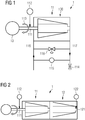
- turbomachine 1 in the form of a turbocompressor with at least one compressor stage (Turbomachine Stage) 11.
- the compressor stage 11 has a rotary shaft 111.
- the torque sensor 112 is a magneto-elastic torque sensor.
- the rotary shaft 111 is made of ferroelectric material.
- the rotary shaft 111 has a ferroelectric coating fixedly connected to the rotary shaft 111.
- At least one operating parameter of the compressor stage 11 is varied.
- a pump control 118 is used.
- the operating parameter is the rotational speed 115 of the rotary shaft 111, which can be varied via the control of the motor 13, and / or the volumetric flow of the fluid which can be varied via the volume flow orifice 114.
- the turbocompressor 1 is a (axially or radially operated) single-shaft compressor (compressor with only one rotary shaft) with only one compressor stage ( FIG. 1 ).
- the front of the compressor stage is denoted by the reference numeral 116 and the back of the compressor stage labeled 117.
- turbocompressor 1 is a multi-stage single-shaft compressor ( FIG. 2 ).
- the turbocompressor 1 has a turbocompressor stage 11 and at least one further turbocompressor stage 12.
- the rotary shaft 111 of the compressor stage 11 and the further rotary shaft 121 of the further compressor stage 12 form a common rotary shaft.
- a further magneto-elastic torque sensor 122 is arranged at the further compressor stage 12. With the help of the further torque sensor 122, the further torque in the region of the further rotation shaft 121 is tapped.
- the torque sensor 112 and the further torque sensor 122 are operated independently of each other.
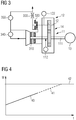
- the turbocompressor 1 is a transmission compressor ( FIG. 3 ).
- the compressor stage 11 and the further compressor stage 12 are connected to each other via a gear 14.
- the rotary shaft 111 is driven.
- the further rotation shaft 12 is coupled to the rotary shaft 111.
- the torque of the rotary shaft 11 is measured via the torque sensor 112 and the further torque of the further rotary shaft 12 via the further torque sensor 122.
- Other components include a volumetric flow meter 330 and devices for measuring the pressure differences 340 and 350 present at the individual compressor stages 11 and 12.
- FIG. 4 it is indicated how, based on the measured torques 40, the progressive development of the torque 41 is predicted.
- M lim (42) This limit can be an alarm value and act as a limit signal.
- operating parameters of the turbo compressor 1 or its compressor stages would be changed so that the alarm value is not reached.
- the alarm value 41 functions as a switch-off signal: the predicted reaching of the alarm value leads to switching-off of the turbocompressor 1.
Landscapes
- Engineering & Computer Science (AREA)
- Mechanical Engineering (AREA)
- General Engineering & Computer Science (AREA)
- Physics & Mathematics (AREA)
- Electromagnetism (AREA)
- General Physics & Mathematics (AREA)
- Control Of Positive-Displacement Air Blowers (AREA)
- Structures Of Non-Positive Displacement Pumps (AREA)
- Supercharger (AREA)
Description
- Verfahren zum Betreiben einer Strömungsmaschine mit Überlastschutz und Strömungsmaschine mit dem Überlastschutz Die Erfindung betrifft ein Verfahren zum Betreiben einer Strömungsmaschine mit Überlastschutz. Die Strömungsmaschine weist mindestens eine Strömungsmaschinen-Stufe auf. Daneben wird eine Strömungsmaschine mit Überlastschutz angegeben.
- Bei einer Strömungsmaschine wird Energie durch ein strömendes Fluid (Gas oder Flüssigkeit) übertragen. Die Energieübertragung erfolgt dabei über ein Laufrad mit Rotations-Welle (Antriebs- oder Abtriebs-Welle). An der Rotations-Welle sind Rotorblätter, Flügel oder Schaufeln angeordnet, die derart geformt sind, dass sich im Fluid-Strom (Volumenstrom) eine Druckdifferenz (Δp) zwischen Vorderseite und Rückseite des Laufrads ergibt.
- Heute gängige Überlastschutzmechanismen bei Strömungsmaschinen, beispielsweise einem Turboverdichter (Turbokompressor), werden in der Regel über den Antrieb der Strömungsmaschine sichergestellt. Eine Leistung eines die Rotations-Welle der Strömungsmaschinen-Stufe antreibenden Motors wird über dessen Anfahrstrom geregelt bzw. begrenzt. Derartige Verfahren sind statisch und wenig flexibel.
- Alternativen dazu sind beispielsweise in den Dokumenten
EP 2 119 917 A1 undEP 2 022 945 A1 zu finden. In beiden Fällen geht es darum, den Überlastschutz durch eine Verbindung zur zu überprüfenden Rotations-Welle sicherzustellen. Dabei findet ein berührungsloses Messen des Dreh-Moments der Rotations-Welle statt. - Das Dokument
WO 01/13082 A1 - Aufgabe der vorliegenden Erfindung ist es, aufzuzeigen, wie in einer Strömungsmaschine ein wirkungsvoller Überlastschutz flexibel und einfach integriert werden kann.
- Zur Lösung der Aufgabe wird ein Verfahren zum Betreiben einer Strömungsmaschine mit mindestens einer Strömungsmaschinen-Stufe angegeben, die mindestens eine Rotations-Welle aufweist, wobei mit dem Verfahren ein Überlastschutz der Rotations-Welle vorgesehen ist und zum Überlastschutz der Rotations-Welle ein Erfassen einer Torsionsspannung der Rotations-Welle im Betrieb der Rotations-Welle durchgeführt wird. Zum Erfassen der Torsionsspannung der Rotations-Welle wird ein Messen eines Drehmoments der Rotations-Welle durchgeführt. Dabei wird zum Messen des Drehmoments der Rotations-Welle ein berührungsloses Mess-Verfahren durchgeführt. Das Verfahren ist dadurch gekennzeichnet, dass das berührungslose Mess-Verfahren mit Hilfe eines magneto-elastischen Drehmoment-Sensors durchgeführt wird und zum Überlastschutz der Rotations-Welle folgende Verfahrensschritte durchgeführt werden: a) Vorhersagen einer Entwicklung des Drehmoments der Rotations-Welle anhand des gemessenen Drehmoments der Rotations-Welle und b) Änderung mindestens eines Betriebsparameters der Strömungsmaschinen-Stufe anhand des Vorhersagens.
- Zur Lösung der Aufgabe wird auch eine Strömungsmaschine mit mindestens einer Strömungsmaschinen-Stufe angegeben, die mindestens eine Rotations-Welle aufweist. Die StrömungsMaschine weist mindestens eine Vorrichtung zum Erfassen einer Torsionsspannung der Rotations-Welle im Betrieb der Rotations-Welle auf. Die Vorrichtung zum Erfassen der Torsionsspannung der Rotationswelle weist einen berührungslosen Drehmoment-Sensor auf, der an der Rotations-Welle angeordnet ist. Die Strömungsmaschine ist dadurch gekennzeichnet, dass die Strömungsmaschine zur Durchführung des hier beschriebenen Verfahrens geeignet und der berührungslose Drehmoment-Sensor ein magneto-elastischer Drehmoment-Sensor ist. Anhand des gemessenen Drehmoments wird die zeitliche Entwicklung des Drehmoments abgeschätzt. So wird beispielsweise abgeschätzt, ob das Drehmoment einen für die Rotations-Welle zulässigen Grenzwert Mlim übersteigen wird.
- Die Strömungsmaschine ist beispielsweise ein Turboverdichter, der mehrere Verdichter-Stufen (Strömungsmaschinen-Stufen) aufweist.
- Das Verfahren kann für eine einstufige Strömungsmaschine angewendet werden. Die Strömungsmaschine verfügt lediglich über eine Strömungsmaschinen-Stufe. In einer besonderen Ausgestaltung wird als Strömungsmaschine eine mehrstufige Strömungsmaschine mit mindestens einer weiteren Strömungsmaschinen-Stufe verwendet, die mindestens eine weitere Rotations-Welle aufweist. Dabei ist mit dem Verfahren ein Überlastschutz der weiteren Rotations-Welle vorgesehen und zum Überlastschutz der weiteren Rotations-Welle wird ein Erfassen einer weiteren Torsionsspannung der weiteren Rotations-Welle im Betrieb der weiteren Rotations-Welle durchgeführt. Die Strömungsmaschine weist mindestens eine weitere Strömungsmaschinen-Stufe mit mindestens einer weiteren Rotations-Welle auf. Dabei sind beispielsweise die Rotations-Welle und die weitere Rotations-Welle identisch. Es gibt lediglich eine gemeinsame Rotations-Welle der Strömungsmaschinen-Stufen. Beispielsweise ist eine derartige mehrstufige Strömungsmaschine ein mehrstufiger Turboverdichter.
- Die grundlegende Idee der Erfindung besteht darin, im Betrieb der Strömungsmaschine das an der Rotations-Welle anliegende Torsions-Drehmoment (und/oder das an der weiteren Rotations-Welle anliegende weitere Torsions-Drehmoment) zu ermitteln. Das ermittelte Torsions-Drehmoment wird für den Überlastschutz der Rotations-Welle verwendet. Dabei wird vorzugsweise im Fall von mehreren Rotations-Wellen jede der Rotations-Wellen separat behandelt. Die Verfahren zum Erfassen der Torsionsspannung und das Erfassen der weiteren Torsionsspannung werden unabhängig voneinander durchgeführt.
- Gemäß einer besonderen Ausgestaltung wird zum Erfassen der Torsionsspannung der weiteren Rotations-Welle ein Messen eines weiteren Drehmoments der weiteren Rotations-Welle durchgeführt.
- In einer besonderen Ausgestaltung werden zum Überlastschutz der weiteren Rotations-Welle mindestens der weiteren Strömungsmaschinen-Stufe folgende weiteren Verfahrensschritte durchgeführt:
- a') Weiteres Vorhersagen einer Entwicklung des Drehmoments der Rotations-Welle anhand des gemessenen Drehmoments der Rotations-Welle und
- b') Weitere Änderung mindestens eines weiteren Betriebsparameters der weiteren Strömungsmaschinen-Stufe anhand des weiteren Vorhersagens.
- Die Messung des jeweiligen Drehmoments erfolgt dabei vorzugsweise kontinuierlich. Dadurch lässt sich eine zeitliche Veränderung des Drehmoments erfassen. Auf der Grundlage des erfassten Drehmoments bzw. der zeitlichen Veränderung des Drehmoments wird die Entwicklung des Drehmoments abgeschätzt. Es wird eine Vorhersage (Prognose) für die Entwicklung des Drehmoments erstellt. Die Entwicklung des Drehmoments wird prognostiziert bzw. extrapoliert. Anhand der Prognose wird abgeschätzt, ob der zulässige Grenzwert Mlim für das Drehmoment überschritten wird. In diesem Fall wird gegengesteuert. Mindestens ein Betriebsparameter der Strömungsmaschinen-Stufe wird derart verändert, dass der Grenzwert Mlim für die Rotations-Welle nicht überschritten, sondern eingehalten wird.
- Beispielsweise wird basierend auf der Prognose der Volumenstrom des Fluids verändert, mit dem die Strömungsmaschine bzw. die Strömungsmaschinen-Stufe betrieben wird. Der Betriebsparameter der Strömungsmaschinen-Stufe ist der Volumenstrom. Denkbar ist auch basierend auf der Prognose eine Änderung einer Drehzahl, mit der die Rotations-Welle der Strömungsmaschinen-Stufe betrieben wird. So könnte die Strömungsmaschine bzw. die Strömungsmaschinen-Stufe herzuntergefahren oder ausgeschaltet werden (Drehzahl 0). Der Betriebsparameter ist die Drehzahl der Rotations-Welle der Strömungsmaschinen-Stufe. Andere Betriebsparameter sind beispielsweise eine Einstellung der Ausrichtung von Leitblechen für das strömende Fluid.
- In einer besonderen Ausgestaltung ist an der weiteren Rotations-Welle ein weiterer Drehmoment-Sensor zum Messen des weiteren Drehmoments der weiteren Rotations-Welle angeordnet. Das Drehmoment und das weitere Drehmoment und eventuell deren zeitliche Änderungen können unabhängig voneinander gemessen werden.
- Zumindest einer der Drehmoment-Sensoren ist vorzugsweise unmittelbar an der jeweiligen Rotations-Welle angeordnet. Mit Hilfe des Drehmoment-Sensors wird das Drehmoment an der Rotations-Welle direkt gemessen. Beispielsweise weist ein Verdichter mehrere Verdichter-Stufen mit jeweils einem Verdichter-Gehäuse auf. Für jedes der Verdichter-Gehäuse wird separat das Drehmoment als Drehmoment-Differenz zwischen Antriebs- und Abtriebs-Welle gemessen.
- Vorzugsweise wird zum Messen des weiteren Drehmoments der weiteren Rotations-Welle ein weiteres berührungsloses Mess-Verfahren durchgeführt. Der weitere Drehmoment-Sensor ist ein weiterer berührungsloser Drehmoment-Sensor.
- Als weiteres berührungsloses Mess-Verfahren wird beispielsweise ein optisches Mess-Verfahren durchgeführt. Vorzugsweise wird das weitere berührungslose Mess-Verfahren mit Hilfe eines weiteren magneto-elastischen Drehmoment-Sensors durchgeführt. Der weitere berührungslose Drehmoment-Sensor ist ein weiterer magneto-elastischer Drehmoment-Sensor.
- Magnetoelastizität basiert auf einer Änderung der magnetischen Permeabilität eines ferroelektrischen Materials aufgrund von mechanischen Kräften, die auf das ferromagnetische Material einwirken. Durch die Verwendung von magneto-elastischen Drehmoment-Sensoren ist es möglich, im Betrieb der Strömungsmaschine direkt Drehmomente zu messen.
- Bisher war die direkte Messung des Drehmoments bei einem Verdichter im Betrieb nur mit erheblichem Aufwand möglich, z.B. durch auf der Rotations-Welle aufgebrachte Dehnungsmess-Streifen und eine Telemetrie zur Weiterleitung der aufgenommenen Signale der rotierenden Rotations-Welle. Durch den Einsatz eines präzisen magneto-elastischen Drehmoment-Sensors, der keinerlei Kontakt zur Rotations-Welle hat und auch keine Behandlung der Rotations-Welle voraussetzt (z.B. Aufbringen von Dehnungsmess-Streifen auf der Rotations-Welle), besteht die Möglichkeit, das beschriebene Verfahren auf einfache Weise direkt einzusetzen.
- Im Hinblick auf das magneto-elastische Mess-Prinzip ist es besonders vorteilhaft, eine die Rotations-Welle der Strömungsmaschinen-Stufe zu verwenden, die komplett aus ferroelektrischem Material besteht. Denkbar ist aber auch, dass die Rotations-Welle lediglich teilweise aus ferroelektrischem Material besteht. Beispielsweise besteht eine ferroelektrische Beschichtung der Rotations-Welle, die fest mit der Rotations-Welle verbunden ist, aus ferroelektrischem Material. Dabei wird sichergestellt, dass durch die Verbindung der ferroelektrischen Beschichtung und der Rotations-Welle das Drehmoment der Rotations-Welle auf die ferroelektrische Beschichtung übertragen werden kann. Durch die Übertragung des Drehmoments ändert sich die Permeabilität des ferroelektrischen Materials der ferroelektrischen Beschichtung. Es resultiert ein detektierbares Signal, das einen Rückschluss auf das an der Rotations-Welle anliegende Drehmoment zulässt.
- Das beschriebene Verfahren ist für alle Arten von Strömungsmaschinen einsetzbar. Gemäß einer besonderen Ausgestaltung wird die Strömungsmaschine aus der Gruppe Gasturbine, Dampfturbine, Turbolader, Pumpe, Verdichter und Hydroturbine ausgewählt. Vorzugsweise ist die Strömungsmaschine ein Verdichter, insbesondere ein Turboverdichter. Unter Turboverdichter werden dabei sowohl mechanisch angetriebene Kompressoren im Öl- und Gasbereich als auch kombinierte Maschinen zur Energieumwandlung wie Gasturbinen verstanden.
- Durch eine hochauflösende Messung des Drehmoments bzw. der Drehmomente lassen sich frühzeitig die Überlastungen extrapolieren und vorhersagen. Dies gilt insbesondere bei hinreichend kleinen zeitlichen Veränderungen. Ein solcher dynamischer Prozess wird dazu genutzt, ein Überschreiten oder Überschwingen der Überlastungsgrenze zu verhindern.
- Anhand mehrerer Ausführungsbeispiele und der dazugehörigen Figuren wird die Erfindung im Folgenden näher beschrieben. Die Figuren sind schematisch und stellen keine maßstabsgetreuen Abbildungen dar.
-
Figur 1 zeigt einen einstufigen Einwellen-Verdichter. -
Figur 2 zeigt einen mehrstufigen Einwellen-Verdichter. -
Figur 3 zeigt einen Getriebeverdichter. -
Figur 4 zeigt eine prognostizierte Entwicklung eines Drehmoments anhand gemessener Drehmomente. - Gegeben ist eine Strömungsmaschine 1 in Form eines Turboverdichters mit mindestens einer Verdichter-Stufe (Strömungsmaschinen-Stufe) 11. Die Verdichter-Stufe 11 weist eine Rotations-Welle 111 auf.
- An der Rotations-Welle 111 ist ein Drehmoment-Sensor 112 zum Messen der Drehmomente der Rotations-Welle angeordnet. Der Drehmoment-Sensor 112 ist ein magneto-elastischer Drehmoment-Sensor.
- Der Turboverdichter 1 weist eine Vorrichtung 100 zur Durchführung eines Verfahrens zum Betreiben des Turboverdichters 1 wobei
- mit dem Verfahren ein Überlastschutz der Rotations-Welle vorgesehen ist und
- zum Überlastschutz der Rotations-Welle ein Erfassen einer Torsionsspannung der Rotations-Welle im Betrieb der Rotations-Welle durchgeführt wird.
- Zum Messen des Drehmoments mit Hilfe des magneto-elastischen Drehmoment-Sensors 112 besteht die Rotations-Welle 111 aus ferroelektrischem Material. In einem alternativen Ausführungsbeispiel weist die Rotations-Welle 111 eine fest mit der Rotations-Welle 111 verbundene ferroelektrische Beschichtung auf.
- In Abhängigkeit von der zeitlichen Änderung des Drehmoments wird mindestens ein Betriebsparameter der Verdichter-Stufe 11 variiert. Dazu wird eine Pump-Regelung 118 eingesetzt. Der Betriebsparameter ist die Drehzahl 115 der Rotations-Welle 111, die über die Ansteuerung des Motors 13 veränderbar ist, und/oder der Volumenstrom des Fluids, der über die Volumenstrom-Messblende 114 veränderbar ist.
- Der Turboverdichter 1 ist ein (axial oder radial betriebener) Einwellen-Verdichter (Verdichter mit nur einer Rotations-Welle) mit nur einer Verdichter-Stufe (
Figur 1 ). Die Vorderseite der Verdichter-Stufe ist mit dem Bezugszeichen 116 und die Rückseite der Verdichter-Stufe mit 117 gekennzeichnet. - Im Unterschied zum Beispiel 1 ist der Turboverdichter 1 ein mehrstufiger Einwellen-Verdichter (
Figur 2 ). Der Turboverdichter 1 verfügt über eine Turboverdichter-Stufe 11 und über mindestens eine weitere Turboverdichter-Stufe 12. - Die Rotations-Welle 111 der Verdichter-Stufe 11 und die weitere Rotations-Welle 121 der weiteren Verdichter-Stufe 12 bilden eine gemeinsame Rotations-Welle.
- An der weiteren Verdichter-Stufe 12 ist ein weiterer magneto-elastischer Drehmoment-Sensor 122 angeordnet. Mit Hilfe des weiteren Drehmoment-Sensors 122 wird das weitere Drehmoment im Bereich der weiteren Rotations-Welle 121 abgegriffen.
- Der Drehmoment-Sensor 112 und der weitere Drehmoment-Sensor 122 werden unabhängig voneinander betrieben.
- Der Turboverdichter 1 ist ein Getriebeverdichter (
Figur 3 ). Die Verdichter-Stufe 11 und die weitere Verdichter-Stufe 12 sind über ein Getriebe 14 miteinander verbunden. Über den Motor 13 wird die Rotations-Welle 111 angetrieben. Über das Getriebe 14 ist die weitere Rotations-Welle 12 an die Rotations-Welle 111 angekoppelt. - Das Drehmoment der Rotations-Welle 11 wird über den Drehmoment-Sensor 112 und das weitere Drehmoment der weiteren Rotations-Welle 12 über den weiteren Drehmoment-Sensor 122 gemessen.
- Über die verstellbare Eintrittsleitapparatur (ELA) 310 und die verstellbare Austrittsleitapparatur (ALA) 320 wird das zu verdichtende Fluid in den Getriebeverdichter eingebracht bzw. das verdichtete Fluid aus dem Getriebeverdichter wieder entfernt.
- Weitere Bestandteile sind eine Volumenstrom-Messblende 330 sowie Vorrichtungen zur Messung der an den einzelnen Verdichter-Stufen 11 und 12 anliegenden Druckdifferenzen 340 und 350.
- Mit
Figur 4 ist angedeutet, wie basierend auf den gemessenen Drehmomenten 40 die fortschreitende Entwicklung des Drehmoments 41 prognostiziert wird. Mit der Prognose kann abgeschätzt werden, ob und wenn ja, wann ein bestimmter Drehmoment-Grenzwert Mlim (42) erreicht wird. Dieser Grenzwert kann ein Alarmwert sein und als Begrenzungs-Signal fungieren. Basierend auf der Prognose des Erreichens des Alarmwerts 41 würden Betriebsparameter des Turboverdichters 1 bzw. dessen Verdichter-Stufen derart geändert werde, dass der Alarmwert nicht erreicht wird. - In einer alternativen Ausgestaltung fungiert der Alarmwert 41 als Abschaltsignal: Das prognostizierte Erreichen des Alarmwerts führt zum Abschalten des Turboverdichters 1.
Claims (11)
- Verfahren zum Betreiben einer Strömungsmaschine (1) mit mindestens einer Strömungsmaschinen-Stufe (11), die mindestens eine Rotations-Welle (111) aufweist, wobei- mit dem Verfahren ein Überlastschutz der Rotations-Welle vorgesehen ist,- zum Überlastschutz der Rotations-Welle ein Erfassen einer Torsionsspannung der Rotations-Welle im Betrieb der Rotations-Welle durchgeführt wird,- zum Erfassen der Torsionsspannung der Rotations-Welle (111) ein Messen eines Drehmoments der Rotations-Welle (111) durchgeführt wird und- zum Messen des Drehmoments der Rotations-Welle (111) ein berührungsloses Mess-Verfahren durchgeführt wird,
dadurch gekennzeichnet, dass- das berührungslose Mess-Verfahren mit Hilfe mindestens eines magneto-elastischen Drehmoment-Sensors (121) durchgeführt wird. und- zum Überlastschutz der Rotations-Welle (111) folgende Verfahrensschritte durchgeführt werden:a) Vorhersagen einer Entwicklung des Drehmoments der Rotations-Welle (111) anhand des gemessenen Drehmoments der Rotations-Welle (111) undb) Änderung mindestens eines Betriebsparameters der Strömungsmaschinen-Stufe (11) anhand des Vorhersagens. - Verfahren nach Anspruch 1, wobei als Strömungsmaschine (1)- eine mehrstufige Strömungsmaschine mit mindestens einer weiteren Strömungsmaschinen-Stufe (12) verwendet wird, die mindestens eine weitere Rotations-Welle (121) aufweist,- mit dem Verfahren ein Überlastschutz der weiteren Rotations-Welle vorgesehen ist und- zum Überlastschutz der weiteren Rotations-Welle ein Erfassen einer weiteren Torsionsspannung der weiteren Rotations-Welle im Betrieb der weiteren Rotations-Welle durchgeführt wird.
- Verfahren nach Anspruch 1 oder 2, wobei zum Erfassen der Torsionsspannung der weiteren Rotations-Welle (121) ein Messen eines weiteren Drehmoments der weiteren Rotations-Welle (121) durchgeführt werden.
- Verfahren nach Anspruch 3, wobei zum Überlastschutz der weiteren Rotations-Welle (121) der weiteren Strömungsmaschinen-Stufen (12) folgende weiteren Verfahrensschritte durchgeführt werden:a') Weiteres Vorhersagen einer Entwicklung des weiteren Drehmoments der weiteren Rotations-Welle (111) anhand des gemessenen weiteren Drehmoments der weiteren Rotations-Welle (121) undb') Weiteres Änderung mindestens eines weiteren Betriebsparameters der weiteren Strömungsmaschinen-Stufe (12) anhand des weiteren Vorhersagens.
- Verfahren nach einem der Ansprüche 1 bis 4, wobei als Betriebsparameter und/oder als weiterer Betriebsparamater ein an der Strömungsmaschinen-Stufe anliegender Volumenstrom eines Fluids, mit dem die Strömungsmaschinen-Stufe betrieben wird, und/oder eine Drehzahl verwendet wird, mit der die Rotations-Welle der Strömungsmaschinen-Stufe angetrieben wird.
- Verfahren nach einem der Ansprüche 1 bis 5, wobei die Strömungsmaschine (1) aus der Gruppe Gasturbine, Dampfturbine, Turbolader, Pumpe, Verdichter und Hydroturbine ausgewählt wird.
- Strömungsmaschine (1) mit mindestens einer Strömungsmaschinen-Stufe (11), die mindestens eine Rotations-Welle (111) aufweist, wobei- die Strömungsmaschine mindestens eine Vorrichtung zum Erfassen einer Torsionsspannung der Rotations-Welle im Betrieb der Rotations-Welle aufweist und- die Vorrichtung zum Erfassen der Torsionsspannung der Rotationswelle einen berührungslosen Drehmoment-Sensor aufweist, der an der Rotations-Welle (111) angeordnet ist, dadurch gekennzeichnet, dass- die Strömungsmaschine (1) zur Durchführung des Verfahrens nach einem der Ansprüche 1 bis 6 geeignet ist und- der berührungslose Drehmoment-Sensor ein magneto-elastischer Drehmoment-Sensor ist.
- Strömungsmaschine nach Anspruch 7, wobei die Strömungsmaschine (1) mindestens eine weitere Strömungsmaschinen-Stufe (12) mit mindestens einer weiteren Rotations-Welle (121) aufweist.
- Strömungsmaschine nach Anspruch 8, wobei an der weiteren Rotations-Welle (121) ein weiterer Drehmoment-Sensor (122) zum Messen des weiteren Drehmoments der weiteren Rotations-Welle (121) angeordnet ist.-
- Strömungsmaschine nach Anspruch 9, wobei der weitere Drehmoment-Sensor (122) ein weiterer berührungsloser Drehmoment-Sensor ist und - der weitere berührungslose Drehmoment-Sensor ein weiterer magneto-elastischer Drehmoment-Sensor ist.
- Strömungsmaschine nach einem der Ansprüche 8 bis 10, wobei die Strömungsmaschine (1) aus der Gruppe Gasturbine, Dampfturbine, Turbolader, Pumpe, Verdichter und Hydroturbine ausgewählt ist.
Applications Claiming Priority (2)
| Application Number | Priority Date | Filing Date | Title |
|---|---|---|---|
| DE102013219752 | 2013-09-30 | ||
| PCT/EP2014/068893 WO2015043914A1 (de) | 2013-09-30 | 2014-09-05 | Verfahren zum betreiben einer strömungsmaschine mit überlastschutz und strömungsmaschine mit einer vorrichtung zur durchführung des verfahrens |
Publications (2)
| Publication Number | Publication Date |
|---|---|
| EP3036408A1 EP3036408A1 (de) | 2016-06-29 |
| EP3036408B1 true EP3036408B1 (de) | 2019-11-27 |
Family
ID=51570475
Family Applications (1)
| Application Number | Title | Priority Date | Filing Date |
|---|---|---|---|
| EP14766934.5A Active EP3036408B1 (de) | 2013-09-30 | 2014-09-05 | Verfahren zum betreiben einer strömungsmaschine mit überlastschutz und strömungsmaschine mit einer vorrichtung zur durchführung des verfahrens |
Country Status (4)
| Country | Link |
|---|---|
| US (1) | US10415422B2 (de) |
| EP (1) | EP3036408B1 (de) |
| CN (1) | CN105765172B (de) |
| WO (1) | WO2015043914A1 (de) |
Cited By (1)
| Publication number | Priority date | Publication date | Assignee | Title |
|---|---|---|---|---|
| EP4074982A1 (de) * | 2021-04-16 | 2022-10-19 | Baker Hughes Holdings LLC | Regelung mit geschlossenem regelkreis, der magnetostriktive abtastung verwendet |
Families Citing this family (4)
| Publication number | Priority date | Publication date | Assignee | Title |
|---|---|---|---|---|
| US10871409B2 (en) | 2017-12-15 | 2020-12-22 | G.E. Avio S.r.l. | SMD-coil-based torque-sensor for tangential field measurement |
| US11493407B2 (en) | 2018-09-28 | 2022-11-08 | Ge Avio S.R.L. | Torque measurement system |
| US11168621B2 (en) * | 2019-03-05 | 2021-11-09 | Pratt & Whitney Canada Corp. | Method and system for operating an engine in a multi-engine aircraft |
| CN110726502B (zh) * | 2019-10-21 | 2025-08-01 | 无锡锡压压缩机有限公司 | 一种调节螺杆压缩机阴转子力矩的方法 |
Family Cites Families (14)
| Publication number | Priority date | Publication date | Assignee | Title |
|---|---|---|---|---|
| US5363317A (en) * | 1992-10-29 | 1994-11-08 | United Technologies Corporation | Engine failure monitor for a multi-engine aircraft having partial engine failure and driveshaft failure detection |
| JP2806731B2 (ja) * | 1993-04-06 | 1998-09-30 | 株式会社クボタ | トルクセンサの零点誤差の補正方法 |
| GB9919065D0 (en) | 1999-08-12 | 1999-10-13 | Fast Technology Gmbh | Transducer Element |
| KR101421704B1 (ko) | 2006-06-29 | 2014-07-22 | 구글 인코포레이티드 | 이미지의 텍스트 인식 |
| US7632059B2 (en) * | 2006-06-29 | 2009-12-15 | General Electric Company | Systems and methods for detecting undesirable operation of a turbine |
| EP2022945A1 (de) * | 2007-08-10 | 2009-02-11 | Siemens Aktiengesellschaft | Verfahren zum Betreiben einer Kraftwerksturbinenanlage sowie Regelungseinrichtung für eine Kraftwerkstrubinenanlage |
| EP2119917A1 (de) * | 2008-05-16 | 2009-11-18 | IHC Holland IE B.V. | Anschlussanordnung und Zentrifugalpumpe mit einer derartigen Anordnung |
| US8417410B2 (en) * | 2008-12-23 | 2013-04-09 | Honeywell International Inc. | Operations support systems and methods with power management |
| FR2962165B1 (fr) * | 2010-07-02 | 2014-05-02 | Turbomeca | Detection de survitesse d'une turbine libre par mesure sur couplemetre |
| CN102135021B (zh) * | 2011-02-25 | 2013-12-25 | 华东理工大学 | 一种工业抽汽冷凝式蒸汽轮机的轴功率预测方法 |
| US9803553B2 (en) * | 2014-04-25 | 2017-10-31 | Rolls-Royce North American Technologies, Inc. | Method to control electric starter generator for gas turbine engines |
| US20160178464A1 (en) * | 2014-12-19 | 2016-06-23 | Rolls-Royce Corporation | Torque sensor monitoring for gas turbine engine |
| US9500136B2 (en) * | 2015-01-06 | 2016-11-22 | General Electric Company | Systems and methods for generating variable ramp rates for turbomachinery |
| EP3330493B1 (de) * | 2016-12-02 | 2019-05-01 | Rolls-Royce Deutschland Ltd & Co KG | Steuerungssystem und -verfahren für einen gasturbinenmotor |
-
2014
- 2014-09-05 US US15/024,457 patent/US10415422B2/en not_active Expired - Fee Related
- 2014-09-05 CN CN201480065389.6A patent/CN105765172B/zh not_active Expired - Fee Related
- 2014-09-05 EP EP14766934.5A patent/EP3036408B1/de active Active
- 2014-09-05 WO PCT/EP2014/068893 patent/WO2015043914A1/de not_active Ceased
Non-Patent Citations (1)
| Title |
|---|
| None * |
Cited By (1)
| Publication number | Priority date | Publication date | Assignee | Title |
|---|---|---|---|---|
| EP4074982A1 (de) * | 2021-04-16 | 2022-10-19 | Baker Hughes Holdings LLC | Regelung mit geschlossenem regelkreis, der magnetostriktive abtastung verwendet |
Also Published As
| Publication number | Publication date |
|---|---|
| EP3036408A1 (de) | 2016-06-29 |
| CN105765172B (zh) | 2018-03-27 |
| US20160230591A1 (en) | 2016-08-11 |
| CN105765172A (zh) | 2016-07-13 |
| US10415422B2 (en) | 2019-09-17 |
| WO2015043914A1 (de) | 2015-04-02 |
Similar Documents
| Publication | Publication Date | Title |
|---|---|---|
| EP3036408B1 (de) | Verfahren zum betreiben einer strömungsmaschine mit überlastschutz und strömungsmaschine mit einer vorrichtung zur durchführung des verfahrens | |
| DE69325375T2 (de) | Verfahren zur überwachung und steuerung eines verdichters und vorrichtung hierfür. | |
| EP2038517B1 (de) | Verfahren zum betrieb einer gasturbine sowie gasturbine zur durchführung des verfahrens | |
| DE102011056644B4 (de) | Verfahren, Vorrichtung und Computerprogramm zur Verdichterzustandsüberwachung | |
| DE10306594A1 (de) | Verfahren und Vorrichtung zum Messen des Drehmomentes in hydraulischen Antriebseinheiten | |
| CH704112B1 (de) | Verfahren und Überwachungssystem zum Bestimmen der Turbinenschaufelverformung. | |
| DE102010016430A1 (de) | Systeme und Verfahren zum Bereitstellen von Pumpschutz für eine Turbinenkomponente | |
| EP2258949A1 (de) | Verfahren zur Ermittlung von charakteristischen Werten, insbesondere Werten , insbesondere von Parametern, eines in einer Anlage eingebundenen elektromotorisch angetriebenen Kreiselpumpenaggregates | |
| EP2039939A1 (de) | Verfahren zur Überwachung einer Energieumwandlungseinrichtung | |
| EP2999857A1 (de) | Verfahren zum betreiben einer strömungsmaschine, bei dem ein wirkungsgrad-kennwert einer stufe ermittelt wird, und strömungsmaschine mit einer vorrichtung zur durchführung des verfahrens | |
| EP2044401A1 (de) | Verfahren zum testen von rotoren | |
| WO2015043915A1 (de) | Verfahren zum betreiben einer strömungsmaschine, in der eine mechanische störung auftritt, und strömungsmaschine mit einer vorrichtung zur durchführung des verfahrens | |
| EP2990609A1 (de) | Verfahren zum Betreiben einer Maschinenanlage mit einem Wellenstrang | |
| DE102015011890A1 (de) | System zum Kompensieren von Rotorschwingungen | |
| EP1014054B1 (de) | Verfahren zur modellbasierten schwingungsdiagnostischen Überwachung rotierender Maschinen | |
| EP1943714A1 (de) | Verfahren zum automatischen überwachen eines generatorbetriebs | |
| Mohamed et al. | Stress analysis of various designs of centrifugal pump impellers using finite element method | |
| EP4111142B1 (de) | Verfahren zur druckverlustregulierung für systeme in fluidführenden rohrleitungen | |
| DE60319245T2 (de) | Verfahren und einrichtung zur bestimmung des zustands einer turbinenschaufel und zur verwendung der gesammelten informationen zur schätzung der lebensdauer der schaufel | |
| EP0809095B1 (de) | Verfahren und Vorrichtung zur Messung des Abtriebsmomentes eines Elektromotors | |
| DE102022214213A1 (de) | Vorrichtung und Verfahren zum Abschätzen mindestens einer Eigenschaft eines rotierenden Systems | |
| DE102009009714A1 (de) | Vorrichtung und Verfahren zur Drehmomentmessung an einer Turbinenwelle | |
| DE102011080836A1 (de) | Rotordreheinrichtung | |
| WO2005085602A1 (de) | Verfahren und vorrichtung zur detektierung von verunreinigungen an turbinenbauteilen | |
| Hedayati Kia et al. | Electrical signatures analysis for condition monitoring of gears |
Legal Events
| Date | Code | Title | Description |
|---|---|---|---|
| PUAI | Public reference made under article 153(3) epc to a published international application that has entered the european phase |
Free format text: ORIGINAL CODE: 0009012 |
|
| 17P | Request for examination filed |
Effective date: 20160324 |
|
| AK | Designated contracting states |
Kind code of ref document: A1 Designated state(s): AL AT BE BG CH CY CZ DE DK EE ES FI FR GB GR HR HU IE IS IT LI LT LU LV MC MK MT NL NO PL PT RO RS SE SI SK SM TR |
|
| AX | Request for extension of the european patent |
Extension state: BA ME |
|
| DAX | Request for extension of the european patent (deleted) | ||
| RAP1 | Party data changed (applicant data changed or rights of an application transferred) |
Owner name: SIEMENS AKTIENGESELLSCHAFT |
|
| STAA | Information on the status of an ep patent application or granted ep patent |
Free format text: STATUS: EXAMINATION IS IN PROGRESS |
|
| 17Q | First examination report despatched |
Effective date: 20181004 |
|
| GRAP | Despatch of communication of intention to grant a patent |
Free format text: ORIGINAL CODE: EPIDOSNIGR1 |
|
| STAA | Information on the status of an ep patent application or granted ep patent |
Free format text: STATUS: GRANT OF PATENT IS INTENDED |
|
| INTG | Intention to grant announced |
Effective date: 20190709 |
|
| GRAS | Grant fee paid |
Free format text: ORIGINAL CODE: EPIDOSNIGR3 |
|
| GRAA | (expected) grant |
Free format text: ORIGINAL CODE: 0009210 |
|
| STAA | Information on the status of an ep patent application or granted ep patent |
Free format text: STATUS: THE PATENT HAS BEEN GRANTED |
|
| AK | Designated contracting states |
Kind code of ref document: B1 Designated state(s): AL AT BE BG CH CY CZ DE DK EE ES FI FR GB GR HR HU IE IS IT LI LT LU LV MC MK MT NL NO PL PT RO RS SE SI SK SM TR |
|
| REG | Reference to a national code |
Ref country code: GB Ref legal event code: FG4D Free format text: NOT ENGLISH |
|
| REG | Reference to a national code |
Ref country code: CH Ref legal event code: EP |
|
| REG | Reference to a national code |
Ref country code: AT Ref legal event code: REF Ref document number: 1206870 Country of ref document: AT Kind code of ref document: T Effective date: 20191215 |
|
| REG | Reference to a national code |
Ref country code: DE Ref legal event code: R096 Ref document number: 502014013139 Country of ref document: DE |
|
| REG | Reference to a national code |
Ref country code: IE Ref legal event code: FG4D Free format text: LANGUAGE OF EP DOCUMENT: GERMAN |
|
| REG | Reference to a national code |
Ref country code: NL Ref legal event code: MP Effective date: 20191127 |
|
| REG | Reference to a national code |
Ref country code: LT Ref legal event code: MG4D |
|
| REG | Reference to a national code |
Ref country code: CH Ref legal event code: NV Representative=s name: SIEMENS SCHWEIZ AG, CH |
|
| PG25 | Lapsed in a contracting state [announced via postgrant information from national office to epo] |
Ref country code: SE Free format text: LAPSE BECAUSE OF FAILURE TO SUBMIT A TRANSLATION OF THE DESCRIPTION OR TO PAY THE FEE WITHIN THE PRESCRIBED TIME-LIMIT Effective date: 20191127 Ref country code: LV Free format text: LAPSE BECAUSE OF FAILURE TO SUBMIT A TRANSLATION OF THE DESCRIPTION OR TO PAY THE FEE WITHIN THE PRESCRIBED TIME-LIMIT Effective date: 20191127 Ref country code: LT Free format text: LAPSE BECAUSE OF FAILURE TO SUBMIT A TRANSLATION OF THE DESCRIPTION OR TO PAY THE FEE WITHIN THE PRESCRIBED TIME-LIMIT Effective date: 20191127 Ref country code: NL Free format text: LAPSE BECAUSE OF FAILURE TO SUBMIT A TRANSLATION OF THE DESCRIPTION OR TO PAY THE FEE WITHIN THE PRESCRIBED TIME-LIMIT Effective date: 20191127 Ref country code: BG Free format text: LAPSE BECAUSE OF FAILURE TO SUBMIT A TRANSLATION OF THE DESCRIPTION OR TO PAY THE FEE WITHIN THE PRESCRIBED TIME-LIMIT Effective date: 20200227 Ref country code: FI Free format text: LAPSE BECAUSE OF FAILURE TO SUBMIT A TRANSLATION OF THE DESCRIPTION OR TO PAY THE FEE WITHIN THE PRESCRIBED TIME-LIMIT Effective date: 20191127 Ref country code: NO Free format text: LAPSE BECAUSE OF FAILURE TO SUBMIT A TRANSLATION OF THE DESCRIPTION OR TO PAY THE FEE WITHIN THE PRESCRIBED TIME-LIMIT Effective date: 20200227 Ref country code: GR Free format text: LAPSE BECAUSE OF FAILURE TO SUBMIT A TRANSLATION OF THE DESCRIPTION OR TO PAY THE FEE WITHIN THE PRESCRIBED TIME-LIMIT Effective date: 20200228 |
|
| PG25 | Lapsed in a contracting state [announced via postgrant information from national office to epo] |
Ref country code: HR Free format text: LAPSE BECAUSE OF FAILURE TO SUBMIT A TRANSLATION OF THE DESCRIPTION OR TO PAY THE FEE WITHIN THE PRESCRIBED TIME-LIMIT Effective date: 20191127 Ref country code: RS Free format text: LAPSE BECAUSE OF FAILURE TO SUBMIT A TRANSLATION OF THE DESCRIPTION OR TO PAY THE FEE WITHIN THE PRESCRIBED TIME-LIMIT Effective date: 20191127 Ref country code: IS Free format text: LAPSE BECAUSE OF FAILURE TO SUBMIT A TRANSLATION OF THE DESCRIPTION OR TO PAY THE FEE WITHIN THE PRESCRIBED TIME-LIMIT Effective date: 20200327 |
|
| PG25 | Lapsed in a contracting state [announced via postgrant information from national office to epo] |
Ref country code: AL Free format text: LAPSE BECAUSE OF FAILURE TO SUBMIT A TRANSLATION OF THE DESCRIPTION OR TO PAY THE FEE WITHIN THE PRESCRIBED TIME-LIMIT Effective date: 20191127 |
|
| PG25 | Lapsed in a contracting state [announced via postgrant information from national office to epo] |
Ref country code: CZ Free format text: LAPSE BECAUSE OF FAILURE TO SUBMIT A TRANSLATION OF THE DESCRIPTION OR TO PAY THE FEE WITHIN THE PRESCRIBED TIME-LIMIT Effective date: 20191127 Ref country code: RO Free format text: LAPSE BECAUSE OF FAILURE TO SUBMIT A TRANSLATION OF THE DESCRIPTION OR TO PAY THE FEE WITHIN THE PRESCRIBED TIME-LIMIT Effective date: 20191127 Ref country code: ES Free format text: LAPSE BECAUSE OF FAILURE TO SUBMIT A TRANSLATION OF THE DESCRIPTION OR TO PAY THE FEE WITHIN THE PRESCRIBED TIME-LIMIT Effective date: 20191127 Ref country code: EE Free format text: LAPSE BECAUSE OF FAILURE TO SUBMIT A TRANSLATION OF THE DESCRIPTION OR TO PAY THE FEE WITHIN THE PRESCRIBED TIME-LIMIT Effective date: 20191127 Ref country code: PT Free format text: LAPSE BECAUSE OF FAILURE TO SUBMIT A TRANSLATION OF THE DESCRIPTION OR TO PAY THE FEE WITHIN THE PRESCRIBED TIME-LIMIT Effective date: 20200419 Ref country code: DK Free format text: LAPSE BECAUSE OF FAILURE TO SUBMIT A TRANSLATION OF THE DESCRIPTION OR TO PAY THE FEE WITHIN THE PRESCRIBED TIME-LIMIT Effective date: 20191127 |
|
| REG | Reference to a national code |
Ref country code: DE Ref legal event code: R097 Ref document number: 502014013139 Country of ref document: DE |
|
| PG25 | Lapsed in a contracting state [announced via postgrant information from national office to epo] |
Ref country code: SK Free format text: LAPSE BECAUSE OF FAILURE TO SUBMIT A TRANSLATION OF THE DESCRIPTION OR TO PAY THE FEE WITHIN THE PRESCRIBED TIME-LIMIT Effective date: 20191127 Ref country code: SM Free format text: LAPSE BECAUSE OF FAILURE TO SUBMIT A TRANSLATION OF THE DESCRIPTION OR TO PAY THE FEE WITHIN THE PRESCRIBED TIME-LIMIT Effective date: 20191127 |
|
| PLBE | No opposition filed within time limit |
Free format text: ORIGINAL CODE: 0009261 |
|
| STAA | Information on the status of an ep patent application or granted ep patent |
Free format text: STATUS: NO OPPOSITION FILED WITHIN TIME LIMIT |
|
| 26N | No opposition filed |
Effective date: 20200828 |
|
| PG25 | Lapsed in a contracting state [announced via postgrant information from national office to epo] |
Ref country code: SI Free format text: LAPSE BECAUSE OF FAILURE TO SUBMIT A TRANSLATION OF THE DESCRIPTION OR TO PAY THE FEE WITHIN THE PRESCRIBED TIME-LIMIT Effective date: 20191127 Ref country code: PL Free format text: LAPSE BECAUSE OF FAILURE TO SUBMIT A TRANSLATION OF THE DESCRIPTION OR TO PAY THE FEE WITHIN THE PRESCRIBED TIME-LIMIT Effective date: 20191127 |
|
| PG25 | Lapsed in a contracting state [announced via postgrant information from national office to epo] |
Ref country code: IT Free format text: LAPSE BECAUSE OF FAILURE TO SUBMIT A TRANSLATION OF THE DESCRIPTION OR TO PAY THE FEE WITHIN THE PRESCRIBED TIME-LIMIT Effective date: 20191127 |
|
| REG | Reference to a national code |
Ref country code: DE Ref legal event code: R119 Ref document number: 502014013139 Country of ref document: DE |
|
| PG25 | Lapsed in a contracting state [announced via postgrant information from national office to epo] |
Ref country code: MC Free format text: LAPSE BECAUSE OF FAILURE TO SUBMIT A TRANSLATION OF THE DESCRIPTION OR TO PAY THE FEE WITHIN THE PRESCRIBED TIME-LIMIT Effective date: 20191127 |
|
| REG | Reference to a national code |
Ref country code: CH Ref legal event code: PL |
|
| GBPC | Gb: european patent ceased through non-payment of renewal fee |
Effective date: 20200905 |
|
| REG | Reference to a national code |
Ref country code: BE Ref legal event code: MM Effective date: 20200930 |
|
| PG25 | Lapsed in a contracting state [announced via postgrant information from national office to epo] |
Ref country code: LU Free format text: LAPSE BECAUSE OF NON-PAYMENT OF DUE FEES Effective date: 20200905 |
|
| PG25 | Lapsed in a contracting state [announced via postgrant information from national office to epo] |
Ref country code: DE Free format text: LAPSE BECAUSE OF NON-PAYMENT OF DUE FEES Effective date: 20210401 Ref country code: FR Free format text: LAPSE BECAUSE OF NON-PAYMENT OF DUE FEES Effective date: 20200930 |
|
| PG25 | Lapsed in a contracting state [announced via postgrant information from national office to epo] |
Ref country code: BE Free format text: LAPSE BECAUSE OF NON-PAYMENT OF DUE FEES Effective date: 20200930 Ref country code: CH Free format text: LAPSE BECAUSE OF NON-PAYMENT OF DUE FEES Effective date: 20200930 Ref country code: LI Free format text: LAPSE BECAUSE OF NON-PAYMENT OF DUE FEES Effective date: 20200930 Ref country code: IE Free format text: LAPSE BECAUSE OF NON-PAYMENT OF DUE FEES Effective date: 20200905 Ref country code: GB Free format text: LAPSE BECAUSE OF NON-PAYMENT OF DUE FEES Effective date: 20200905 |
|
| REG | Reference to a national code |
Ref country code: AT Ref legal event code: MM01 Ref document number: 1206870 Country of ref document: AT Kind code of ref document: T Effective date: 20200905 |
|
| PG25 | Lapsed in a contracting state [announced via postgrant information from national office to epo] |
Ref country code: AT Free format text: LAPSE BECAUSE OF NON-PAYMENT OF DUE FEES Effective date: 20200905 |
|
| PG25 | Lapsed in a contracting state [announced via postgrant information from national office to epo] |
Ref country code: TR Free format text: LAPSE BECAUSE OF FAILURE TO SUBMIT A TRANSLATION OF THE DESCRIPTION OR TO PAY THE FEE WITHIN THE PRESCRIBED TIME-LIMIT Effective date: 20191127 Ref country code: MT Free format text: LAPSE BECAUSE OF FAILURE TO SUBMIT A TRANSLATION OF THE DESCRIPTION OR TO PAY THE FEE WITHIN THE PRESCRIBED TIME-LIMIT Effective date: 20191127 Ref country code: CY Free format text: LAPSE BECAUSE OF FAILURE TO SUBMIT A TRANSLATION OF THE DESCRIPTION OR TO PAY THE FEE WITHIN THE PRESCRIBED TIME-LIMIT Effective date: 20191127 |
|
| PG25 | Lapsed in a contracting state [announced via postgrant information from national office to epo] |
Ref country code: MK Free format text: LAPSE BECAUSE OF FAILURE TO SUBMIT A TRANSLATION OF THE DESCRIPTION OR TO PAY THE FEE WITHIN THE PRESCRIBED TIME-LIMIT Effective date: 20191127 |