EP3036453B1 - Transmission à double embrayage pour véhicule automobile - Google Patents
Transmission à double embrayage pour véhicule automobile Download PDFInfo
- Publication number
- EP3036453B1 EP3036453B1 EP14744117.4A EP14744117A EP3036453B1 EP 3036453 B1 EP3036453 B1 EP 3036453B1 EP 14744117 A EP14744117 A EP 14744117A EP 3036453 B1 EP3036453 B1 EP 3036453B1
- Authority
- EP
- European Patent Office
- Prior art keywords
- gear
- shaft
- transmission input
- coupling device
- gears
- Prior art date
- Legal status (The legal status is an assumption and is not a legal conclusion. Google has not performed a legal analysis and makes no representation as to the accuracy of the status listed.)
- Active
Links
- 230000005540 biological transmission Effects 0.000 title claims description 144
- 230000009977 dual effect Effects 0.000 title claims description 25
- 230000008878 coupling Effects 0.000 claims description 144
- 238000010168 coupling process Methods 0.000 claims description 144
- 238000005859 coupling reaction Methods 0.000 claims description 144
- 238000004804 winding Methods 0.000 claims description 15
- 230000007935 neutral effect Effects 0.000 description 22
- 230000000750 progressive effect Effects 0.000 description 4
- 238000010276 construction Methods 0.000 description 3
- 238000009434 installation Methods 0.000 description 2
- 239000007787 solid Substances 0.000 description 2
- 230000003247 decreasing effect Effects 0.000 description 1
- 238000010586 diagram Methods 0.000 description 1
Images


Classifications
-
- F—MECHANICAL ENGINEERING; LIGHTING; HEATING; WEAPONS; BLASTING
- F16—ENGINEERING ELEMENTS AND UNITS; GENERAL MEASURES FOR PRODUCING AND MAINTAINING EFFECTIVE FUNCTIONING OF MACHINES OR INSTALLATIONS; THERMAL INSULATION IN GENERAL
- F16H—GEARING
- F16H3/00—Toothed gearings for conveying rotary motion with variable gear ratio or for reversing rotary motion
- F16H3/006—Toothed gearings for conveying rotary motion with variable gear ratio or for reversing rotary motion power being selectively transmitted by parallel flow paths, e.g. dual clutch transmissions
-
- F—MECHANICAL ENGINEERING; LIGHTING; HEATING; WEAPONS; BLASTING
- F16—ENGINEERING ELEMENTS AND UNITS; GENERAL MEASURES FOR PRODUCING AND MAINTAINING EFFECTIVE FUNCTIONING OF MACHINES OR INSTALLATIONS; THERMAL INSULATION IN GENERAL
- F16H—GEARING
- F16H3/00—Toothed gearings for conveying rotary motion with variable gear ratio or for reversing rotary motion
- F16H3/02—Toothed gearings for conveying rotary motion with variable gear ratio or for reversing rotary motion without gears having orbital motion
- F16H3/08—Toothed gearings for conveying rotary motion with variable gear ratio or for reversing rotary motion without gears having orbital motion exclusively or essentially with continuously meshing gears, that can be disengaged from their shafts
- F16H2003/0807—Toothed gearings for conveying rotary motion with variable gear ratio or for reversing rotary motion without gears having orbital motion exclusively or essentially with continuously meshing gears, that can be disengaged from their shafts with gear ratios in which the power is transferred by axially coupling idle gears to each other
-
- F—MECHANICAL ENGINEERING; LIGHTING; HEATING; WEAPONS; BLASTING
- F16—ENGINEERING ELEMENTS AND UNITS; GENERAL MEASURES FOR PRODUCING AND MAINTAINING EFFECTIVE FUNCTIONING OF MACHINES OR INSTALLATIONS; THERMAL INSULATION IN GENERAL
- F16H—GEARING
- F16H3/00—Toothed gearings for conveying rotary motion with variable gear ratio or for reversing rotary motion
- F16H3/02—Toothed gearings for conveying rotary motion with variable gear ratio or for reversing rotary motion without gears having orbital motion
- F16H3/08—Toothed gearings for conveying rotary motion with variable gear ratio or for reversing rotary motion without gears having orbital motion exclusively or essentially with continuously meshing gears, that can be disengaged from their shafts
- F16H2003/0826—Toothed gearings for conveying rotary motion with variable gear ratio or for reversing rotary motion without gears having orbital motion exclusively or essentially with continuously meshing gears, that can be disengaged from their shafts wherein at least one gear on the input shaft, or on a countershaft is used for two different forward gear ratios
-
- F—MECHANICAL ENGINEERING; LIGHTING; HEATING; WEAPONS; BLASTING
- F16—ENGINEERING ELEMENTS AND UNITS; GENERAL MEASURES FOR PRODUCING AND MAINTAINING EFFECTIVE FUNCTIONING OF MACHINES OR INSTALLATIONS; THERMAL INSULATION IN GENERAL
- F16H—GEARING
- F16H3/00—Toothed gearings for conveying rotary motion with variable gear ratio or for reversing rotary motion
- F16H3/02—Toothed gearings for conveying rotary motion with variable gear ratio or for reversing rotary motion without gears having orbital motion
- F16H3/08—Toothed gearings for conveying rotary motion with variable gear ratio or for reversing rotary motion without gears having orbital motion exclusively or essentially with continuously meshing gears, that can be disengaged from their shafts
- F16H3/087—Toothed gearings for conveying rotary motion with variable gear ratio or for reversing rotary motion without gears having orbital motion exclusively or essentially with continuously meshing gears, that can be disengaged from their shafts characterised by the disposition of the gears
- F16H3/093—Toothed gearings for conveying rotary motion with variable gear ratio or for reversing rotary motion without gears having orbital motion exclusively or essentially with continuously meshing gears, that can be disengaged from their shafts characterised by the disposition of the gears with two or more countershafts
- F16H2003/0931—Toothed gearings for conveying rotary motion with variable gear ratio or for reversing rotary motion without gears having orbital motion exclusively or essentially with continuously meshing gears, that can be disengaged from their shafts characterised by the disposition of the gears with two or more countershafts each countershaft having an output gear meshing with a single common gear on the output shaft
-
- F—MECHANICAL ENGINEERING; LIGHTING; HEATING; WEAPONS; BLASTING
- F16—ENGINEERING ELEMENTS AND UNITS; GENERAL MEASURES FOR PRODUCING AND MAINTAINING EFFECTIVE FUNCTIONING OF MACHINES OR INSTALLATIONS; THERMAL INSULATION IN GENERAL
- F16H—GEARING
- F16H3/00—Toothed gearings for conveying rotary motion with variable gear ratio or for reversing rotary motion
- F16H3/02—Toothed gearings for conveying rotary motion with variable gear ratio or for reversing rotary motion without gears having orbital motion
- F16H3/08—Toothed gearings for conveying rotary motion with variable gear ratio or for reversing rotary motion without gears having orbital motion exclusively or essentially with continuously meshing gears, that can be disengaged from their shafts
- F16H3/087—Toothed gearings for conveying rotary motion with variable gear ratio or for reversing rotary motion without gears having orbital motion exclusively or essentially with continuously meshing gears, that can be disengaged from their shafts characterised by the disposition of the gears
- F16H3/093—Toothed gearings for conveying rotary motion with variable gear ratio or for reversing rotary motion without gears having orbital motion exclusively or essentially with continuously meshing gears, that can be disengaged from their shafts characterised by the disposition of the gears with two or more countershafts
- F16H2003/0933—Toothed gearings for conveying rotary motion with variable gear ratio or for reversing rotary motion without gears having orbital motion exclusively or essentially with continuously meshing gears, that can be disengaged from their shafts characterised by the disposition of the gears with two or more countershafts with coaxial countershafts
-
- F—MECHANICAL ENGINEERING; LIGHTING; HEATING; WEAPONS; BLASTING
- F16—ENGINEERING ELEMENTS AND UNITS; GENERAL MEASURES FOR PRODUCING AND MAINTAINING EFFECTIVE FUNCTIONING OF MACHINES OR INSTALLATIONS; THERMAL INSULATION IN GENERAL
- F16H—GEARING
- F16H2200/00—Transmissions for multiple ratios
- F16H2200/003—Transmissions for multiple ratios characterised by the number of forward speeds
- F16H2200/0069—Transmissions for multiple ratios characterised by the number of forward speeds the gear ratios comprising ten forward speeds
Definitions
- the invention relates to a double clutch transmission for a motor vehicle with the features of the preamble of claim 1.
- Double clutch transmissions with two transmission input shafts, two drive shafts and a plurality of gearwheels are known, the gearwheels forming a plurality of dual gear planes.
- a double clutch transmission for a motor vehicle with two friction clutches, two transmission input shafts and two drive shafts and several synchronizing devices.
- the first transmission input shaft is connectable or connected to a drive motor via the first friction clutch and the second transmission input shaft is connected via the second friction clutch.
- Three fixed gears are assigned to each of the transmission input shafts.
- One drive shaft has six idler gears and the other drive shaft has two idler gears.
- the two outer fixed gears assigned to the outer, second transmission input shaft mesh with two idler gears on the two drive shafts and / or an idler gear and therefore form two double gear planes.
- the intermediate gear is interposed in one dual-wheel plane to reverse the rotation and thus to implement a reverse gear.
- the corresponding synchronizing devices are arranged on the drive shafts.
- the dual clutch transmission has eight forward gears and is suitable for a front transverse construction in a motor vehicle.
- the forward gears are power shiftable.
- a similar dual clutch transmission is also known with two dual gear levels and a total of six gear levels.
- This double clutch transmission also has eight forward gears with at least seven powershiftable forward gears.
- the double clutch transmission is suitable for a front transverse construction in a motor vehicle.
- a double clutch transmission for front-transverse applications is known.
- Two friction clutches, two transmission input shafts and two drive shafts are provided.
- a further hollow shaft is arranged on the second, outer transmission input shaft such that the two transmission input shafts and the further hollow shaft extend coaxially to one another.
- Two fixed gears are arranged on the further hollow shaft.
- the further hollow shaft can be connected in a rotationally fixed manner to the outer transmission input shaft via a synchronizing device.
- the inner and outer transmission input shafts also each have a fixed gear. This results in a total of four wheel planes, which are designed as double wheel planes.
- a hollow shaft is supported on one of the drive shafts, the hollow shaft being rotatably connected to the drive shaft via a synchronizing device.
- a fixed gear and an idler gear are arranged on the hollow shaft.
- several winding gears can be realized, whereby eight or nine powershiftable forward gears can be realized.
- the increments in the translation of the first six forward gears are designed to decrease.
- a double clutch transmission in which exactly one double wheel plane is provided with three gear wheels designed as idler wheels.
- At least one hollow shaft is assigned to each of the two drive shafts, at least one toothed wheel designed as an idler gear being loosely arranged on at least one of the hollow shafts.
- a coupling device is arranged on this hollow shaft so that the idler gear can be connected in a rotationally fixed manner to the hollow shaft.
- the hollow shaft can be connected in a rotationally fixed manner to the corresponding drive shaft by means of a further coupling device.
- Two coaxially arranged hollow shafts are arranged on one of the drive shafts, the inner hollow shaft being rotatably connected to the drive shaft via a coupling device.
- a gear is rotatably arranged on the inner and the outer hollow shaft.
- the invention is therefore based on the object of designing and developing the dual clutch transmission mentioned at the outset in such a way that it is compact Building dual clutch transmission is provided with in particular a decreasing, in particular approximately progressive gear ratio.
- a hollow shaft is preferably assigned at least two gear pairs, one gear pair being assigned to the inner transmission input shaft and the other gear pair being assigned to the outer transmission input shaft.
- a winding path can be implemented via this hollow shaft.
- a gearwheel designed as an idler gear is arranged, this gearwheel being rotatably connected to the outer hollow shaft via a further coupling device, and the two hollow shafts being rotatably connected to one another via this coupling device.
- six gear levels with five gear stages and one dual gear level with the three idler gears are provided.
- Each of the transmission input shafts has at least one gear wheel designed as an idler gear and each has at least one coupling device for connecting the at least one idler gear to the corresponding gear input shaft.
- Each of the transmission input shaft is preferably assigned three gearwheels, preferably two idler gears and a fixed gear.
- a coupling device is arranged between the two idler gears.
- a parking lock gear is assigned to at least one of the drive shafts.
- an intermediate shaft with a gearwheel is provided, this gearwheel being arranged to mesh with one of the gearwheels on one of the drive shafts.
- An output pinion is assigned to each of the drive shafts, the output pinions preferably having different sizes. Ten forward gears are provided.
- At least the first and the tenth forward gear and in particular a further forward gear are designed as a winding gear.
- the ten forward gears have an approximately progressive gear ratio. Because the dual clutch transmission is short, it is particularly suitable for front-transverse installation.
- At least one of the coupling devices can be implemented as a synchronizing device; in an advantageous variant, all coupling devices are implemented as a synchronizing device. The disadvantages mentioned at the outset are therefore avoided and corresponding advantages are achieved.
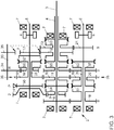
- the double clutch transmissions 1, 2 each have a first, inner transmission input shaft 3 and a second, outer transmission input shaft 4.
- the two transmission input shafts 3, 4 are arranged coaxially to one another.
- the transmission input shaft 4 is hollow.
- the transmission input shaft 3 extends within the transmission input shaft 4.
- the transmission input shaft 3 can be designed as a solid shaft or alternatively as a hollow shaft. In a preferred embodiment, the transmission input shaft 3 is designed as a solid shaft.
- the two double clutch transmissions 1, 2 each have two drive shafts 5, 6.
- the drive shafts 5, 6 are arranged parallel to the concentrically arranged transmission input shafts 3, 4.
- the transmission input shafts 3, 4 are each connected or connectable to the drive shafts 5, 6 via gear pairs or gear stages.
- the transmission input shaft 3, the transmission input shaft 4 and the two drive shafts 5, 6 are each supported via bearings 7.
- the first transmission input shaft 3 is assigned three gearwheels, namely a central gearwheel 9 and a gearwheel 10 close to the clutch.
- the terms “close to the clutch” and “remote from the clutch” are used here in relation to adjacent gearwheels in order to express whether the gearwheels in the Fig. 1 and 3 in each case to the left or right of one another, that is to say either arranged remote from the clutch or close to the clutch.
- the gear 8 remote from the clutch is designed as a fixed gear.
- the central gear 9 and the clutch-close gear 10 are designed as idler gears.
- This coupling device S2 or S4 arranged between them is designed to be double-acting.
- the idler gears in the form of the gear wheels 9, 10 can be connected in a rotationally fixed manner to the inner transmission input shaft 3.
- the second transmission input shaft 4 is also assigned three gearwheels, namely a gearwheel 11 remote from the clutch, a central gearwheel 12 and a gearwheel 13 close to the clutch. Between the two gearwheels 11, 12 designed as idler gears, there is a coupling device S3 (cf. Fig. 1 ) or S5 (cf. Fig. 3 ) arranged.
- the gearwheel 11 remote from the clutch is arranged on the inner transmission input shaft 3 or is rotatably mounted, but is non-rotatably connected to the outer transmission input shaft 4 via the coupling device S3 or S5 and is therefore assigned to the outer transmission input shaft 4.
- the gear 13 close to the clutch is designed as a fixed gear in the case of the double clutch transmission 1 and as an idler gear in the case of the double clutch transmission 2.
- a further coupling device S3 (see FIG. 2) is located between the clutch gear 13 and the corresponding bearing 7. Fig. 3 ) for connecting the gear 13, which is designed as an idler gear, to the outer transmission input shaft 4.
- the gear wheels 14, 15, 16, 17 are assigned to the first drive shaft 5.
- the second drive shaft 6, the gears 18, 19, 20, 21 are assigned.
- the gear 18 is designed as an idler gear and meshes with the gear 8 on the first transmission input shaft 3 remote from the clutch.
- the gear 18 is connected via the coupling device S4 (cf. Fig. 1 ) or S1 (cf. Fig. 3 ) rotatably connected to the second drive shaft 6 or to the hollow shaft 36.
- the gear 19 meshes with the gear 10 close to the clutch on the first transmission input shaft 3.
- the dual clutch transmission 1 may be described in more detail using Fig. 1 To be received.
- the three, adjacent clutch gears 14, 15, 16 assigned to the first drive shaft 5 are arranged on a hollow shaft 22 in a rotationally fixed manner.
- the hollow shaft 22 can be connected in a rotationally fixed manner to the first drive shaft 5 via a coupling device S1 arranged close to the coupling of these three gear wheels 14, 15, 16.
- the coupling device S1 is double-acting.
- the clutch gear 17 is designed as an idler gear and can also be detachably connected to the drive shaft 5 by means of the coupling device S1.
- the gear 18 arranged on the second drive shaft 6 remote from the clutch meshes with the gear 8 remote from the clutch on the first transmission input shaft 3 and forms a gear pair for a second forward gear.
- Two coaxial hollow shafts 23, 24 are arranged on the second drive shaft 6.
- the inner hollow shaft 23 is non-rotatably connected to the gear 21 near the clutch.
- the outer hollow shaft 24 is arranged on the inner hollow shaft 23.
- the outer hollow shaft 24 is non-rotatably connected to the coupling device S5 and the gear 19.
- the gear 20 designed as an idler gear is arranged.
- the gear wheel 20 can be connected in a rotationally fixed manner to the outer hollow shaft 24 and thus to the gear wheel 19 via the coupling device S5.
- the gear 19 meshes with the gear 10 on the first transmission input shaft 3 and forms a gear stage for an eighth forward gear.
- the gear 21 meshes with the gear 12 on the outer transmission input shaft 4 and forms a gear stage for the seventh forward gear.
- An intermediate shaft 25 with two further gear wheels 26, 27 is arranged parallel to the second drive shaft 6.
- the gear 26 meshes with the gear 20 and forms a gear stage, this gear stage being assigned to a reverse gear.
- the gear 27 meshes with the gear 13 on the outer transmission input shaft 4.
- the two gears 21 and 12 form a gear stage which is assigned to a seventh forward gear.
- a parking lock gear 28 is also arranged on the second drive shaft 6 near the coupling of the gear 21.
- the output pinion b is arranged near the parking lock wheel 28.
- the forward gears 2, 3, 4, 6, 7, 8 and 9 are not designed as winding turns.
- the forward gears one, five and ten are designed as winding gears, with one Power flow of the turn path over several gear stages winds.
- the gear stages of the second and eighth forward gears are involved in shifting the reverse gear.
- the gear stages of the second, third and fourth forward gears are involved in the shifting of the first forward gear.
- the gear stages of the sixth, seventh and eighth forward gears are involved in shifting the fifth forward gear.
- the gear stages of the eighth, ninth and seventh forward gears are involved in shifting the tenth forward gear.
- the dual clutch transmission 1 has ten forward gears.
- the double clutch transmission is of such a short construction that it can be installed in a front transverse installation position in motor vehicles.
- Each of the two drive shafts 5, 6 is an output pinion a, b (cf. Fig. 1 and Fig. 3 ) assigned, the two output pinions a, b having different sizes. This enables a progressive translation step.
- This double gear plane 29 and 38 has the gears 15, 10 and 19.
- the gearwheels 15, 10 and 19 can be coupled in a rotationally fixed manner to the drive shaft 5 or the inner transmission input shaft 3 by means of the coupling devices S1, S2 (cf. Fig. 1 ).
- the gear 19 can be coupled in a rotationally fixed manner to the gear 20 or to the inner hollow shaft 23 by means of the coupling device S5 (cf. Fig. 1 ).
- the shifting of the individual forward gears and the reverse gear of the dual clutch transmission 1 may be based on the Fig. 1 and Fig. 2 be discussed in more detail.
- Concerning. of the representations in the Fig. 2 and 4 the switching positions for the coupling devices S1 to S6, that is, the representation of the Fig. 2 and 4 may be stated that the "0" symbolizes a neutral position, an “r” a switching position to the right, an “l” a switching position to the left, the second, outer input shaft 4 with the character “h” and the "” v "the inner, first transmission input shaft 3 is to be designated.
- the coupling devices S1 and S3 are arranged in a neutral position.
- the coupling device S2 is arranged in the right, clutch-close switching position and thus connects the gearwheel 10 to the inner transmission input shaft 3 in a rotationally fixed manner.
- the coupling devices S4 and S5 are arranged in the left, clutch-remote switching position.
- the power flow is from the outer transmission input shaft 4 to the corresponding fixed gear, namely the gear 13, the gear 27 arranged in mesh with the gear 13 on the intermediate shaft 25, the corresponding gear 26 and thus the meshing gear 20 arranged on the second drive shaft 6 transmitted.
- the coupling device S5 now transfers the power flow to the outer hollow shaft 24 and thus to the gearwheels 19 and 10 of the gearwheel stage assigned to the eighth forward gear. Since the coupling device S2 transmits the power flow to the inner transmission input shaft 3, the fixed gear 8 and the meshing gear 18 of the gear stage of the second forward gear are now driven. The power flow is transmitted to the second drive shaft 6 and thus to the output pinion b via the coupling device S4.
- the coupling devices S1 and S5 are in a neutral position.
- the coupling devices S2, S3, S4 are in the left, clutch-remote switching position.
- the power flow is transmitted from the outer transmission input shaft 4 to the coupling device S3, to the gear stage with the gears 11 and 16 assigned to the third forward gear.
- the power flow is transmitted via the hollow shaft 22 to the gear stage 14 and 9 assigned to the fourth forward gear.
- the power flow is transmitted to the gear 8 and the meshing gear 18 of the gear stage of the second forward gear via the coupling device S2.
- the power flow is transmitted to the second drive shaft 6 via the closed coupling device S4.
- the coupling devices S1, S2, S3 and S5 are in the neutral position.
- the coupling device S4 is in the left, clutch-remote switching position. The power flow is transmitted to the second drive shaft 6 via the gears 8 and 18 and the coupling device S4.
- the power flow is transmitted via the outer transmission input shaft 4.
- the coupling devices S1 and S3 are in the left switch position, the coupling devices S2, S4 and S5 are in the neutral position.
- the power flow is transmitted to the first drive shaft 5 via the gear stage with the gears 11 and 16 by means of the coupling device S1.
- the power flow is transmitted via the inner transmission input shaft 3.
- the coupling devices S1 and S2 are in the left switch position, the coupling devices S3, S4, S5 are in the neutral position.
- the power flow is transmitted to the drive shaft 5 via the gear stage with the gears 9 and 14 and the coupling devices S2 and S1.
- the coupling device S1 is in the left switch position.
- the coupling devices S2 and S4 are in the neutral position.
- the coupling devices S3 and S5 are in the right switch position.
- the power flow is via the transmission input shaft 4, via the coupling device S3, the gear stage with the gears 12 and 21 (which is assigned to the seventh forward gear), via the coupling device S5, onto the outer hollow shaft 24, the gear stage with the gears 19, 10 and 15, namely via the double gear plane 29 (which is assigned to the forward gears eight and six) to the hollow shaft 22 and via the coupling device S1 to the drive shaft 5.
- the power flow is transmitted via the inner transmission input shaft 3.
- the coupling device S1 is in the left switching position and the coupling device S2 is in the right switching position.
- the remaining coupling devices S3, S4, S5 are in the neutral position.
- the power flow is transmitted via the coupling device S2 and the gear stage with the gears 15 and 10, the hollow shaft 22, the coupling device S1 to the drive shaft 5.
- the power flow is transmitted via the outer transmission input shaft 4.
- the coupling devices S1, S2 and S5 are in the neutral position.
- the coupling devices S3 and S4 are in the right switch position.
- the power flow is transmitted via the coupling device S3 to the gear stage with the gears 12 and 21, to the inner hollow shaft 23 and via the coupling device S4 and to the second drive shaft 6.
- the power flow is transmitted via the inner transmission input shaft 3.
- the coupling devices S2, S4 and S5 are in the right switch position.
- the power flow is transmitted from the inner transmission input shaft 3 via the coupling device S2 to the gear stage with the gears 10 and 19, the hollow shaft 24, the coupling device S5 and thus to the hollow shaft 23, the coupling device S4 from there to the drive shaft 6.
- the power flow is transmitted to the outer transmission input shaft 4.
- the coupling device S1 is in the right switch position and the remaining coupling devices S2 to S5 are in the neutral position.
- the power flow is based on the outer transmission input shaft 4 thus transmitted to the coupling device S1 and thus also to the first drive shaft 5 via the two gearwheels 13 and 17.
- the power flow is transmitted via the inner transmission input shaft 3.
- the coupling devices S1, S2, S3 and S5 are in the right switch position.
- the coupling device S4 is in the neutral position.
- the power flow is transmitted via the gear stage with the gears 10 and 19.
- the outer hollow shaft 24 driven in this way is connected in a rotationally fixed manner to the inner hollow shaft 23 via the coupling device S5.
- the gear stage with the two gears 12 and 21 is driven.
- the coupling device S3 connects the gear 12 to the outer transmission input shaft 4, the gear 13 designed as a fixed gear and thus the gear 17 on the first drive shaft 5 are now also driven.
- the power flow to the drive shaft 5 is closed via the coupling device S1.
- the gear 14 remote from the clutch on the first drive shaft 5 has an unspecified receptacle which is open to the bearing 7.
- the gearwheel 14 partially engages around the bearing 7. Close to the clutch next to the gearwheel 14, between the gearwheel 15 and the gearwheel 14 a parking lock gear 30 is arranged on the first drive shaft 5 in a rotationally fixed manner.
- the gear wheel 15 is connected in a rotationally fixed manner to the coupling device S6 via a hollow shaft 31.
- the gear 16 is loosely arranged on the hollow shaft 31 between the coupling device S6 and the gear 15. If the coupling device S6 is shifted into the left switching position remote from the clutch, the gearwheel 16 is rotatably connected to the hollow shaft 31 and then to the gearwheel 15.
- a coupling body 32 is arranged near the coupling device S6. If the coupling device S6 is moved into the right shift position, clutch position close to the clutch, then the hollow shaft 31 and thus the gearwheel 15 are connected in a rotationally fixed manner to the first drive shaft 5.
- the gear 17 is arranged adjacent to the clutch body 32 on the drive shaft 5 close to the clutch.
- the output pinion a is arranged adjacent to the gear 17.
- An intermediate shaft 33 is arranged parallel to the drive shaft 5.
- the intermediate shaft 33 has two gear wheels 34, 35.
- the two gear wheels 34, 35 are arranged on the intermediate shaft 33 in a rotationally fixed manner.
- the gear 34 meshes with the gear 16 on the hollow shaft 31.
- the gear 35 meshes with the gear 12 on the outer transmission input shaft 4.
- the gear 18 remote from the clutch is designed as an idler gear.
- the coupling device S1 is rotatably connected to a hollow shaft 36. If the coupling device S1 is now moved into the left switching position remote from the clutch, the gearwheel 18 is connected to the hollow shaft 36 in a rotationally fixed manner.
- the idler gear 19 is loosely mounted on the hollow shaft 36 adjacent to the coupling device S1. If the coupling device S1 is moved into the switching position on the right, close to the clutch, the gearwheel 19 is connected to the hollow shaft 36 in a rotationally fixed manner.
- the gear 20 is arranged on the hollow shaft 36 in a rotationally fixed manner.
- the gear 20 is arranged adjacent to the gear 19 close to the clutch.
- a coupling body 37 is arranged in a rotationally fixed manner on an end region of the hollow shaft 36 which is not near the coupling.
- the coupling body 37 can be connected to the coupling device S2.
- the coupling device S2 is rotatably connected to the second drive shaft 6.
- a fixed gear 21 is arranged on the drive shaft 6 close to the coupling device S2.
- the fixed gear 21 is arranged between the output pinion b and the coupling device S2.
- the double clutch transmission 2 has exactly one double wheel plane 38, the double wheel plane 38 having the three gear wheels 15, 10 and 19 designed as idler wheels.
- the dual clutch transmission 2 has a total of six wheel planes and exactly one double wheel plane 38.
- the gear stages with the gears 9 and 14 are assigned to the second forward gear.
- the gear stage with the gears 10 and 15 is assigned to the fourth forward gear.
- the gear stage with the gears 11 and 20 is assigned to the fifth forward gear.
- the gear stage with the gears 10 and 19 is assigned to the sixth forward gear.
- the gear stage with the gears 12 and 17 is assigned to the seventh forward gear.
- the gear stage with the gears 8 and 18 is assigned to the eighth forward gear.
- the gear stage with the gears 13 and 21 is assigned to the ninth forward gear.
- the first, third and tenth forward gears are each designed as a winding gear. The power flow winds with respect to the first forward gear via the gear stages of the forward gears five, eight and two.
- the third forward gear is also designed as a winding gear, the power flow winding through the gear stages of the forward gears five, six and four.
- the tenth forward gear is also designed as a winding gear, with the power flow winding through the gear stages of the forward gears six, five and nine.
- the switching states of the coupling devices S1, S2, S3, S4, S5, S6 when switching the ten forward gears and the reverse gear may be discussed in more detail below (cf. Fig. 3 and 4 ):
- the coupling devices S1, S2, S3 and S5 are in the neutral position.
- the coupling device S4 is in the right, clutch-close switching position.
- the coupling device S6 is in the left switching position remote from the clutch.
- the power flow extends over the gear stage assigned to the fourth forward gear with the gears 10 and 15, the gear stage associated with the reverse gear with the gears 16 and 34 via the intermediate shaft 33 and the gear stage with the gears 35, 12 and 17 (which is assigned to the seventh forward gear is), on the first drive shaft 5.
- the reverse gear is accordingly designed as a winding gear.
- the drive torque is transmitted via the outer transmission input shaft 4.
- the coupling devices S1, S4 and S5 are in the left switch position.
- the coupling devices S2, S3 and S6 are in the neutral position.
- the power flow is transmitted from the outer transmission input shaft 4 to the gear stage of the fifth forward gear with the gears 11 and 20.
- the hollow shaft 36 driven in this way transfers the power flow via the coupling device S1 to the gear stage of the eighth forward gear with the gears 8 and 18 to the inner transmission input shaft 3.
- the closed coupling device S4 the power flow is transferred to the gear stage associated with the second forward gear with the gears 9 and 14 and thus transmitted to the drive shaft 5.
- the power flow is transmitted via the inner transmission input shaft 3.
- the coupling devices S1, S2, S3, S5 and S6 are in the neutral position.
- the coupling device S4 is in the left switch position. As a result, the power flow is transmitted from the inner transmission input shaft 3 via the gears 9 and 14 to the first drive shaft 5.
- the coupling devices S1 and S6 are arranged in the right switch position.
- the coupling devices S2, S3 and S4 are arranged in the neutral position.
- the coupling device S5 is arranged in the left switch position.
- the power flow is transmitted via the inner transmission input shaft 3.
- the coupling devices S1, S2, S3 and S5 are arranged in the neutral position.
- the coupling devices S4 and S6 are arranged in the switching position on the right, close to the clutch.
- the power flow is transmitted from the inner transmission input shaft 3 via the coupling device S4 to the gear stage with the gears 10 and 15, via the hollow shaft 31 to the coupling device S6 and from there to the clutch body 32 and thus the drive shaft 5.
- the power flow is transmitted via the outer transmission input shaft 4.
- the coupling devices S1, S3, S4 and S6 are in the neutral position.
- the coupling devices S2 and S5 are in the left, clutch-remote switching position. The power flow is thus transmitted via the outer transmission input shaft 4 to the gear stage with the gears 11 and 20, the coupling device S2 and thus to the second drive shaft 6.
- the power flow is transmitted via the inner transmission input shaft 3.
- the coupling devices S1 and S4 are in the right switch position.
- the coupling device S2 is in the left switch position.
- the coupling devices S3, S5 and S6 are in the neutral position. The power flow is thus transmitted from the inner transmission input shaft 3 via the gear stage with the gears 19 and 10 to the hollow shaft 36 and from there via the coupling device S2 to the second drive shaft 6.
- the coupling devices S1, S2, S3, S4 and S6 are in the neutral position.
- the coupling device S5 is arranged in the right switching position.
- the gearwheel stage with the gearwheels 12 and 17 assigned to the seventh forward gear transmits from the power flow starting from the outer transmission input shaft 4 to the first drive shaft 5.
- the coupling devices S1 and S2 When the eighth forward gear is engaged, the coupling devices S1 and S2 are arranged in the left shift position and the remaining coupling devices S3 to S6 are arranged in the neutral position.
- the power flow is based on the inner transmission input shaft 3 via the gear stage assigned to the eighth forward gear with the Transfer gears 8 and 18 via the coupling device S1 to the hollow shaft 36 and from there via the coupling device S2 to the second drive shaft 6.
- the coupling device S3 When the ninth forward gear is engaged, the coupling device S3 is in the left shift position, the other coupling devices S1, S2, S4, S5, S6 are in the neutral position.
- the power flow is transmitted from the outer transmission input shaft 4 to the second drive shaft 6 via the gear stage assigned to the ninth forward gear with the gears 13 and 21.
- the coupling devices S1 and S4 When the tenth forward gear is engaged, the coupling devices S1 and S4 are in the right shift position. The coupling devices S3 and S5 are in the left switch position. The coupling devices S2 and S6 are in the neutral position.
- the power flow is transmitted from the inner transmission input shaft 3 via the gears 10 and 19 assigned to the sixth gear stage to the hollow shaft 36 and thus to the gears 20 and 11 assigned to the fifth gear stage.
- the outer transmission input shaft 4 is driven via the coupling device S5 and thus the gear 13 connected in a rotationally fixed manner via the coupling device S3 and thus the gear stage assigned to the ninth forward gear with the gears 21 and 13 and thus then the second drive shaft 6.
- At least one of the coupling devices can be implemented as a synchronization device
Landscapes
- Engineering & Computer Science (AREA)
- General Engineering & Computer Science (AREA)
- Mechanical Engineering (AREA)
- Structure Of Transmissions (AREA)
Claims (6)
- Transmission à double embrayage (1, 2) pour un véhicule automobile avec un premier arbre d'entrée de transmission (3), avec un deuxième arbre d'entrée de transmission (4), avec deux arbres d'entraînement (5, 6), avec plusieurs roues dentées (8 à 21), avec plusieurs dispositifs de couplage (S1, S2, S3, S4, S5, S6), dans laquelle le premier arbre d'entrée de transmission (3) peut être relié ou est relié par un premier embrayage à friction et le deuxième arbre d'entrée de transmission (4) peut être relié ou est relié par un deuxième embrayage à friction avec un moteur d'entraînement, dans laquelle les roues dentées (8 à 21) sont agencées de façon à s'engrener, de sorte que plusieurs rapports de marche avant sont commutables au moyen des dispositifs de couplage (S1 à S6), dans laquelle au moins un rapport de marche avant est réalisé sous forme d'engrenage à enroulement, et dans laquelle un flux de puissance de l'engrenage à enroulement s'enroule sur plusieurs étages d'engrenage, dans laquelle exactement un plan de roue double (29, 38) est prévu avec trois roues dentées réalisées sous la forme de roues folles (10, 15, 19) et au moins un arbre creux (22, 23, 24; 31, 36) est associé respectivement aux deux arbres d'entraînement (5, 6) et dans laquelle au moins une roue dentée réalisée sous forme d'une rolle folle (20, 16, 19) est agencée de manière lâche sur au moins l'un des arbres creux (24, 31, 36) et deux arbres creux agencés de manière coaxiale (23, 24) sont agencés sur l'un des arbres d'entraînement (6), dans laquelle l'arbre creux intérieur (23) comporte une roue dentée solidaire en rotation (21) et peut être relié de manière solidaire en rotation par le dispositif de couplage (S4) avec l'arbre d'entraînement (6), dans laquelle l'arbre creux extérieur (24) comporte une roue dentée solidaire en rotation (19), caractérisée en ce qu'une roue dentée réalisée sous forme de roue folle (20) est agencée sur l'arbre creux extérieur (24), ladite roue dentée (20) pouvant être reliée de manière solidaire en rotation par un autre dispositif de couplage (S5) avec l'arbre creux extérieur et les deux arbres creux (23, 24) pouvant être reliés l'un à l'autre de manière solidaire en rotation par un autre dispositif de couplage (S5).
- Transmission à double embrayage selon la revendication 1, caractérisée en ce que le flux de puissance d'au moins un engrenage à enroulement s'enroule sur le plan de roue double (29, 38).
- Transmission à double embrayage selon l'une des revendications précédentes, caractérisée en ce qu'au moins une roue dentée réalisée sous forme de roue folle (9, 10, 11, 12; 9, 10, 11, 12, 13) et respectivement au moins un dispositif de couplage (S2, S3; S4, S5) sont associés à chacun des arbres d'entrée de transmission (3, 4) pour la liaison des roues folles avec l'arbre d'entrée de transmission correspondant (3, 4).
- Transmission à double embrayage selon l'une des revendications précédentes, caractérisée en ce qu'un arbre intermédiaire (25, 33) avec une roue dentée (26, 34) est prévu pour la réalisation d'un rapport de marche arrière, dans laquelle ladite roue dentée (26, 34) est agencée de façon à s'engrener avec l'une des roues dentées sur l'un des arbres d'entraînement (5, 6) .
- Transmission à double embrayage selon l'une des revendications précédentes, caractérisée en ce qu'un pignon à la sortie (a, b) est associé à chacun des arbres d'entraînement (5, 6), les pignons à la sortie (a, b) présentant des dimensions différentes.
- Transmission à double embrayage selon l'une des revendications précédentes, caractérisée en ce que dix rapports de marche avant sont prévus, au moins le premier et le dixième rapport de marche avant et, en particulier, un autre rapport de marche avant étant conçus sous forme d'un engrenage à enroulement.
Applications Claiming Priority (2)
| Application Number | Priority Date | Filing Date | Title |
|---|---|---|---|
| DE102013216385.1A DE102013216385A1 (de) | 2013-08-19 | 2013-08-19 | Doppelkupplungsgetriebe für ein Kraftfahrzeug |
| PCT/EP2014/066146 WO2015024737A1 (fr) | 2013-08-19 | 2014-07-28 | Transmission à double embrayage pour véhicule automobile |
Publications (2)
| Publication Number | Publication Date |
|---|---|
| EP3036453A1 EP3036453A1 (fr) | 2016-06-29 |
| EP3036453B1 true EP3036453B1 (fr) | 2020-02-26 |
Family
ID=51225564
Family Applications (1)
| Application Number | Title | Priority Date | Filing Date |
|---|---|---|---|
| EP14744117.4A Active EP3036453B1 (fr) | 2013-08-19 | 2014-07-28 | Transmission à double embrayage pour véhicule automobile |
Country Status (5)
| Country | Link |
|---|---|
| EP (1) | EP3036453B1 (fr) |
| KR (1) | KR101769721B1 (fr) |
| CN (1) | CN105452718B (fr) |
| DE (1) | DE102013216385A1 (fr) |
| WO (1) | WO2015024737A1 (fr) |
Families Citing this family (8)
| Publication number | Priority date | Publication date | Assignee | Title |
|---|---|---|---|---|
| DE102013019118B4 (de) * | 2013-11-15 | 2018-05-17 | Daimler Ag | Doppelkupplungsgetriebe |
| DE102016202915A1 (de) | 2016-02-25 | 2017-08-31 | Ford Global Technologies, Llc | Doppelkupplungsgetriebe für Kraftfahrzeuge |
| DE102016202914A1 (de) | 2016-02-25 | 2017-08-31 | Ford Global Technologies, Llc | Doppelkupplungsgetriebe für Kraftfahrzeuge |
| CN107420490A (zh) * | 2016-05-23 | 2017-12-01 | Fev欧洲有限责任公司 | 用于小型车的变速器和具有此类变速器的混合系统 |
| KR102453352B1 (ko) * | 2017-10-11 | 2022-10-07 | 현대자동차 주식회사 | 차량용 변속장치 |
| DE102018222025A1 (de) * | 2018-12-18 | 2020-06-18 | Zf Friedrichshafen Ag | Getriebeeinrichtung für ein Kraftfahrzeug |
| DE102018222055A1 (de) * | 2018-12-18 | 2020-06-18 | Zf Friedrichshafen Ag | Getriebeeinrichtung für ein Kraftfahrzeug |
| CN112096804A (zh) * | 2020-08-07 | 2020-12-18 | 宁波上中下自动变速器有限公司 | 一种自动变速器及具有其的汽车 |
Family Cites Families (15)
| Publication number | Priority date | Publication date | Assignee | Title |
|---|---|---|---|---|
| DE102006054271A1 (de) * | 2006-11-17 | 2008-06-12 | Zf Friedrichshafen Ag | Doppelkupplungsgetriebe eines Kraftfahrzeugs |
| JP2009030753A (ja) * | 2007-07-30 | 2009-02-12 | Aisin Ai Co Ltd | 6組の前進変速ギヤ対を有する変速機 |
| DE102007049265B4 (de) | 2007-10-15 | 2016-11-10 | Zf Friedrichshafen Ag | Doppelkupplungsgetriebe |
| EP2189318B1 (fr) * | 2008-11-19 | 2012-06-06 | Honda Motor Co., Ltd. | Transmission hybride à double embrayage |
| CN101713448B (zh) * | 2009-03-13 | 2012-07-04 | 浙江吉利汽车研究院有限公司 | 双离合器式自动变速器 |
| DE102009002357B4 (de) | 2009-04-14 | 2019-06-19 | Zf Friedrichshafen Ag | Doppelkupplungsgetriebe |
| DE102009002348B4 (de) | 2009-04-14 | 2017-05-04 | Zf Friedrichshafen Ag | Doppelkupplungsgetriebe |
| US8104367B2 (en) * | 2009-05-20 | 2012-01-31 | GM Global Technology Operations LLC | Seven speed dual clutch transmission |
| DE102010053130B4 (de) | 2010-10-27 | 2019-12-19 | Iav Gmbh Ingenieurgesellschaft Auto Und Verkehr | Doppelkupplungsgetriebe für Front-Quer-Anwendungen |
| DE102010055644A1 (de) * | 2010-12-22 | 2012-06-28 | Volkswagen Ag | Doppelkupplungswindungsgetriebe |
| DE102011016661A1 (de) * | 2011-04-05 | 2012-10-11 | Getrag Getriebe- Und Zahnradfabrik Hermann Hagenmeyer Gmbh & Cie Kg | Doppelkupplungsgetriebe und Verfahren zu dessen Betreiben |
| US8733194B2 (en) * | 2011-04-27 | 2014-05-27 | Gm Global Technology Operations, Llc | Dual clutch multi-speed transmission |
| DE102011089727A1 (de) * | 2011-12-23 | 2013-06-27 | Zf Friedrichshafen Ag | Doppelkupplungsgetriebe |
| DE102012017079A1 (de) * | 2012-08-29 | 2014-05-15 | Daimler Ag | Doppelkupplungsgetriebe |
| JP6137809B2 (ja) * | 2012-11-13 | 2017-05-31 | アイシン・エーアイ株式会社 | デュアルクラッチ式自動変速機 |
-
2013
- 2013-08-19 DE DE102013216385.1A patent/DE102013216385A1/de not_active Withdrawn
-
2014
- 2014-07-28 KR KR1020167007132A patent/KR101769721B1/ko not_active Expired - Fee Related
- 2014-07-28 CN CN201480046208.5A patent/CN105452718B/zh not_active Expired - Fee Related
- 2014-07-28 WO PCT/EP2014/066146 patent/WO2015024737A1/fr not_active Ceased
- 2014-07-28 EP EP14744117.4A patent/EP3036453B1/fr active Active
Non-Patent Citations (1)
| Title |
|---|
| None * |
Also Published As
| Publication number | Publication date |
|---|---|
| KR101769721B1 (ko) | 2017-08-18 |
| CN105452718B (zh) | 2018-01-19 |
| WO2015024737A1 (fr) | 2015-02-26 |
| KR20160044557A (ko) | 2016-04-25 |
| EP3036453A1 (fr) | 2016-06-29 |
| DE102013216385A1 (de) | 2015-02-19 |
| CN105452718A (zh) | 2016-03-30 |
Similar Documents
| Publication | Publication Date | Title |
|---|---|---|
| EP3036453B1 (fr) | Transmission à double embrayage pour véhicule automobile | |
| EP3121483B1 (fr) | Boîte de vitesses à double embrayage | |
| DE102009017537B3 (de) | Doppelkupplungsgetriebe mit drei Triebwellen | |
| DE102010053130B4 (de) | Doppelkupplungsgetriebe für Front-Quer-Anwendungen | |
| EP2111514B1 (fr) | Boîte de vitesses à double embrayage d'un véhicule automobile | |
| DE112015000830B4 (de) | Volllastschaltbares Doppelkupplungsgetriebe | |
| DE102014215156B4 (de) | Gruppengetriebe eines Kraftfahrzeugs | |
| DE102011117046B4 (de) | Doppelkupplungswindungsgetriebe | |
| EP2428699B1 (fr) | Boîte de vitesses à double embrayage dotée d'une marche arrière déplacée | |
| DE102005005163B4 (de) | Doppelkupplungsgetriebe | |
| DE102011076386A1 (de) | Doppelkupplungsgetriebe | |
| EP3036454B1 (fr) | Transmission à double embrayage | |
| DE102011076382A1 (de) | Doppelkupplungsgetriebe | |
| WO2009050075A2 (fr) | Transmission à double embrayage | |
| DE202009005634U1 (de) | Doppelkupplungsgetriebe | |
| EP2739878B1 (fr) | Boîte de vitesses pour un véhicule automobile | |
| DE102012100536B4 (de) | Schaltgetriebe mit Zusatzgang | |
| DE102009018450B4 (de) | Doppelkupplungsgetriebe | |
| DE102007049268B4 (de) | Doppelkupplungsgetriebe | |
| WO2012084631A1 (fr) | Procédé pour la modification d'une boîte de vitesses manuelle | |
| DE102013216387A1 (de) | Doppelkupplungsgetriebe | |
| DE102016119931B4 (de) | Doppelkupplungsgetriebe mit Brückenwelle | |
| DE102020005168B3 (de) | Doppelkupplungsgetriebe | |
| DE102014218104B4 (de) | Doppelkupplungsgetriebe | |
| DE102011055610A1 (de) | Schaltgetriebe für Fahrzeuge |
Legal Events
| Date | Code | Title | Description |
|---|---|---|---|
| PUAI | Public reference made under article 153(3) epc to a published international application that has entered the european phase |
Free format text: ORIGINAL CODE: 0009012 |
|
| 17P | Request for examination filed |
Effective date: 20160321 |
|
| AK | Designated contracting states |
Kind code of ref document: A1 Designated state(s): AL AT BE BG CH CY CZ DE DK EE ES FI FR GB GR HR HU IE IS IT LI LT LU LV MC MK MT NL NO PL PT RO RS SE SI SK SM TR |
|
| AX | Request for extension of the european patent |
Extension state: BA ME |
|
| DAX | Request for extension of the european patent (deleted) | ||
| GRAP | Despatch of communication of intention to grant a patent |
Free format text: ORIGINAL CODE: EPIDOSNIGR1 |
|
| STAA | Information on the status of an ep patent application or granted ep patent |
Free format text: STATUS: GRANT OF PATENT IS INTENDED |
|
| INTG | Intention to grant announced |
Effective date: 20191015 |
|
| GRAS | Grant fee paid |
Free format text: ORIGINAL CODE: EPIDOSNIGR3 |
|
| GRAA | (expected) grant |
Free format text: ORIGINAL CODE: 0009210 |
|
| STAA | Information on the status of an ep patent application or granted ep patent |
Free format text: STATUS: THE PATENT HAS BEEN GRANTED |
|
| AK | Designated contracting states |
Kind code of ref document: B1 Designated state(s): AL AT BE BG CH CY CZ DE DK EE ES FI FR GB GR HR HU IE IS IT LI LT LU LV MC MK MT NL NO PL PT RO RS SE SI SK SM TR |
|
| REG | Reference to a national code |
Ref country code: GB Ref legal event code: FG4D Free format text: NOT ENGLISH |
|
| REG | Reference to a national code |
Ref country code: CH Ref legal event code: EP |
|
| REG | Reference to a national code |
Ref country code: DE Ref legal event code: R096 Ref document number: 502014013698 Country of ref document: DE |
|
| REG | Reference to a national code |
Ref country code: AT Ref legal event code: REF Ref document number: 1238011 Country of ref document: AT Kind code of ref document: T Effective date: 20200315 |
|
| REG | Reference to a national code |
Ref country code: IE Ref legal event code: FG4D Free format text: LANGUAGE OF EP DOCUMENT: GERMAN |
|
| PG25 | Lapsed in a contracting state [announced via postgrant information from national office to epo] |
Ref country code: NO Free format text: LAPSE BECAUSE OF FAILURE TO SUBMIT A TRANSLATION OF THE DESCRIPTION OR TO PAY THE FEE WITHIN THE PRESCRIBED TIME-LIMIT Effective date: 20200526 Ref country code: FI Free format text: LAPSE BECAUSE OF FAILURE TO SUBMIT A TRANSLATION OF THE DESCRIPTION OR TO PAY THE FEE WITHIN THE PRESCRIBED TIME-LIMIT Effective date: 20200226 Ref country code: RS Free format text: LAPSE BECAUSE OF FAILURE TO SUBMIT A TRANSLATION OF THE DESCRIPTION OR TO PAY THE FEE WITHIN THE PRESCRIBED TIME-LIMIT Effective date: 20200226 |
|
| REG | Reference to a national code |
Ref country code: NL Ref legal event code: MP Effective date: 20200226 |
|
| REG | Reference to a national code |
Ref country code: LT Ref legal event code: MG4D |
|
| PG25 | Lapsed in a contracting state [announced via postgrant information from national office to epo] |
Ref country code: IS Free format text: LAPSE BECAUSE OF FAILURE TO SUBMIT A TRANSLATION OF THE DESCRIPTION OR TO PAY THE FEE WITHIN THE PRESCRIBED TIME-LIMIT Effective date: 20200626 Ref country code: LV Free format text: LAPSE BECAUSE OF FAILURE TO SUBMIT A TRANSLATION OF THE DESCRIPTION OR TO PAY THE FEE WITHIN THE PRESCRIBED TIME-LIMIT Effective date: 20200226 Ref country code: SE Free format text: LAPSE BECAUSE OF FAILURE TO SUBMIT A TRANSLATION OF THE DESCRIPTION OR TO PAY THE FEE WITHIN THE PRESCRIBED TIME-LIMIT Effective date: 20200226 Ref country code: GR Free format text: LAPSE BECAUSE OF FAILURE TO SUBMIT A TRANSLATION OF THE DESCRIPTION OR TO PAY THE FEE WITHIN THE PRESCRIBED TIME-LIMIT Effective date: 20200527 Ref country code: HR Free format text: LAPSE BECAUSE OF FAILURE TO SUBMIT A TRANSLATION OF THE DESCRIPTION OR TO PAY THE FEE WITHIN THE PRESCRIBED TIME-LIMIT Effective date: 20200226 Ref country code: BG Free format text: LAPSE BECAUSE OF FAILURE TO SUBMIT A TRANSLATION OF THE DESCRIPTION OR TO PAY THE FEE WITHIN THE PRESCRIBED TIME-LIMIT Effective date: 20200526 |
|
| PG25 | Lapsed in a contracting state [announced via postgrant information from national office to epo] |
Ref country code: NL Free format text: LAPSE BECAUSE OF FAILURE TO SUBMIT A TRANSLATION OF THE DESCRIPTION OR TO PAY THE FEE WITHIN THE PRESCRIBED TIME-LIMIT Effective date: 20200226 |
|
| PG25 | Lapsed in a contracting state [announced via postgrant information from national office to epo] |
Ref country code: LT Free format text: LAPSE BECAUSE OF FAILURE TO SUBMIT A TRANSLATION OF THE DESCRIPTION OR TO PAY THE FEE WITHIN THE PRESCRIBED TIME-LIMIT Effective date: 20200226 Ref country code: CZ Free format text: LAPSE BECAUSE OF FAILURE TO SUBMIT A TRANSLATION OF THE DESCRIPTION OR TO PAY THE FEE WITHIN THE PRESCRIBED TIME-LIMIT Effective date: 20200226 Ref country code: SK Free format text: LAPSE BECAUSE OF FAILURE TO SUBMIT A TRANSLATION OF THE DESCRIPTION OR TO PAY THE FEE WITHIN THE PRESCRIBED TIME-LIMIT Effective date: 20200226 Ref country code: RO Free format text: LAPSE BECAUSE OF FAILURE TO SUBMIT A TRANSLATION OF THE DESCRIPTION OR TO PAY THE FEE WITHIN THE PRESCRIBED TIME-LIMIT Effective date: 20200226 Ref country code: EE Free format text: LAPSE BECAUSE OF FAILURE TO SUBMIT A TRANSLATION OF THE DESCRIPTION OR TO PAY THE FEE WITHIN THE PRESCRIBED TIME-LIMIT Effective date: 20200226 Ref country code: SM Free format text: LAPSE BECAUSE OF FAILURE TO SUBMIT A TRANSLATION OF THE DESCRIPTION OR TO PAY THE FEE WITHIN THE PRESCRIBED TIME-LIMIT Effective date: 20200226 Ref country code: ES Free format text: LAPSE BECAUSE OF FAILURE TO SUBMIT A TRANSLATION OF THE DESCRIPTION OR TO PAY THE FEE WITHIN THE PRESCRIBED TIME-LIMIT Effective date: 20200226 Ref country code: DK Free format text: LAPSE BECAUSE OF FAILURE TO SUBMIT A TRANSLATION OF THE DESCRIPTION OR TO PAY THE FEE WITHIN THE PRESCRIBED TIME-LIMIT Effective date: 20200226 Ref country code: PT Free format text: LAPSE BECAUSE OF FAILURE TO SUBMIT A TRANSLATION OF THE DESCRIPTION OR TO PAY THE FEE WITHIN THE PRESCRIBED TIME-LIMIT Effective date: 20200719 |
|
| REG | Reference to a national code |
Ref country code: DE Ref legal event code: R097 Ref document number: 502014013698 Country of ref document: DE |
|
| PLBE | No opposition filed within time limit |
Free format text: ORIGINAL CODE: 0009261 |
|
| STAA | Information on the status of an ep patent application or granted ep patent |
Free format text: STATUS: NO OPPOSITION FILED WITHIN TIME LIMIT |
|
| PG25 | Lapsed in a contracting state [announced via postgrant information from national office to epo] |
Ref country code: IT Free format text: LAPSE BECAUSE OF FAILURE TO SUBMIT A TRANSLATION OF THE DESCRIPTION OR TO PAY THE FEE WITHIN THE PRESCRIBED TIME-LIMIT Effective date: 20200226 |
|
| 26N | No opposition filed |
Effective date: 20201127 |
|
| PG25 | Lapsed in a contracting state [announced via postgrant information from national office to epo] |
Ref country code: SI Free format text: LAPSE BECAUSE OF FAILURE TO SUBMIT A TRANSLATION OF THE DESCRIPTION OR TO PAY THE FEE WITHIN THE PRESCRIBED TIME-LIMIT Effective date: 20200226 Ref country code: MC Free format text: LAPSE BECAUSE OF FAILURE TO SUBMIT A TRANSLATION OF THE DESCRIPTION OR TO PAY THE FEE WITHIN THE PRESCRIBED TIME-LIMIT Effective date: 20200226 Ref country code: PL Free format text: LAPSE BECAUSE OF FAILURE TO SUBMIT A TRANSLATION OF THE DESCRIPTION OR TO PAY THE FEE WITHIN THE PRESCRIBED TIME-LIMIT Effective date: 20200226 |
|
| REG | Reference to a national code |
Ref country code: CH Ref legal event code: PL |
|
| GBPC | Gb: european patent ceased through non-payment of renewal fee |
Effective date: 20200728 |
|
| REG | Reference to a national code |
Ref country code: BE Ref legal event code: MM Effective date: 20200731 |
|
| PG25 | Lapsed in a contracting state [announced via postgrant information from national office to epo] |
Ref country code: CH Free format text: LAPSE BECAUSE OF NON-PAYMENT OF DUE FEES Effective date: 20200731 Ref country code: GB Free format text: LAPSE BECAUSE OF NON-PAYMENT OF DUE FEES Effective date: 20200728 Ref country code: LI Free format text: LAPSE BECAUSE OF NON-PAYMENT OF DUE FEES Effective date: 20200731 Ref country code: FR Free format text: LAPSE BECAUSE OF NON-PAYMENT OF DUE FEES Effective date: 20200731 Ref country code: LU Free format text: LAPSE BECAUSE OF NON-PAYMENT OF DUE FEES Effective date: 20200728 |
|
| PG25 | Lapsed in a contracting state [announced via postgrant information from national office to epo] |
Ref country code: BE Free format text: LAPSE BECAUSE OF NON-PAYMENT OF DUE FEES Effective date: 20200731 |
|
| PG25 | Lapsed in a contracting state [announced via postgrant information from national office to epo] |
Ref country code: IE Free format text: LAPSE BECAUSE OF NON-PAYMENT OF DUE FEES Effective date: 20200728 |
|
| REG | Reference to a national code |
Ref country code: AT Ref legal event code: MM01 Ref document number: 1238011 Country of ref document: AT Kind code of ref document: T Effective date: 20200728 |
|
| PG25 | Lapsed in a contracting state [announced via postgrant information from national office to epo] |
Ref country code: AT Free format text: LAPSE BECAUSE OF NON-PAYMENT OF DUE FEES Effective date: 20200728 |
|
| PG25 | Lapsed in a contracting state [announced via postgrant information from national office to epo] |
Ref country code: TR Free format text: LAPSE BECAUSE OF FAILURE TO SUBMIT A TRANSLATION OF THE DESCRIPTION OR TO PAY THE FEE WITHIN THE PRESCRIBED TIME-LIMIT Effective date: 20200226 Ref country code: MT Free format text: LAPSE BECAUSE OF FAILURE TO SUBMIT A TRANSLATION OF THE DESCRIPTION OR TO PAY THE FEE WITHIN THE PRESCRIBED TIME-LIMIT Effective date: 20200226 Ref country code: CY Free format text: LAPSE BECAUSE OF FAILURE TO SUBMIT A TRANSLATION OF THE DESCRIPTION OR TO PAY THE FEE WITHIN THE PRESCRIBED TIME-LIMIT Effective date: 20200226 |
|
| PG25 | Lapsed in a contracting state [announced via postgrant information from national office to epo] |
Ref country code: MK Free format text: LAPSE BECAUSE OF FAILURE TO SUBMIT A TRANSLATION OF THE DESCRIPTION OR TO PAY THE FEE WITHIN THE PRESCRIBED TIME-LIMIT Effective date: 20200226 Ref country code: AL Free format text: LAPSE BECAUSE OF FAILURE TO SUBMIT A TRANSLATION OF THE DESCRIPTION OR TO PAY THE FEE WITHIN THE PRESCRIBED TIME-LIMIT Effective date: 20200226 |
|
| PGFP | Annual fee paid to national office [announced via postgrant information from national office to epo] |
Ref country code: DE Payment date: 20220731 Year of fee payment: 9 |
|
| REG | Reference to a national code |
Ref country code: DE Ref legal event code: R119 Ref document number: 502014013698 Country of ref document: DE |
|
| PG25 | Lapsed in a contracting state [announced via postgrant information from national office to epo] |
Ref country code: DE Free format text: LAPSE BECAUSE OF NON-PAYMENT OF DUE FEES Effective date: 20240201 |
|
| P01 | Opt-out of the competence of the unified patent court (upc) registered |
Free format text: CASE NUMBER: UPC_APP_327291/2023 Effective date: 20230523 |