EP3036510B1 - Druckbasierte gasströmungssteuerung mit dynamischer selbstkalibrierung - Google Patents
Druckbasierte gasströmungssteuerung mit dynamischer selbstkalibrierung Download PDFInfo
- Publication number
- EP3036510B1 EP3036510B1 EP14769464.0A EP14769464A EP3036510B1 EP 3036510 B1 EP3036510 B1 EP 3036510B1 EP 14769464 A EP14769464 A EP 14769464A EP 3036510 B1 EP3036510 B1 EP 3036510B1
- Authority
- EP
- European Patent Office
- Prior art keywords
- pressure
- gas
- gas flow
- cavity
- flow
- Prior art date
- Legal status (The legal status is an assumption and is not a legal conclusion. Google has not performed a legal analysis and makes no representation as to the accuracy of the status listed.)
- Active
Links
Images




Classifications
-
- G—PHYSICS
- G05—CONTROLLING; REGULATING
- G05D—SYSTEMS FOR CONTROLLING OR REGULATING NON-ELECTRIC VARIABLES
- G05D7/00—Control of flow
- G05D7/06—Control of flow characterised by the use of electric means
- G05D7/0617—Control of flow characterised by the use of electric means specially adapted for fluid materials
- G05D7/0629—Control of flow characterised by the use of electric means specially adapted for fluid materials characterised by the type of regulator means
- G05D7/0635—Control of flow characterised by the use of electric means specially adapted for fluid materials characterised by the type of regulator means by action on throttling means
-
- G—PHYSICS
- G01—MEASURING; TESTING
- G01F—MEASURING VOLUME, VOLUME FLOW, MASS FLOW OR LIQUID LEVEL; METERING BY VOLUME
- G01F1/00—Measuring the volume flow or mass flow of fluid or fluent solid material wherein the fluid passes through a meter in a continuous flow
- G01F1/76—Devices for measuring mass flow of a fluid or a fluent solid material
-
- G—PHYSICS
- G01—MEASURING; TESTING
- G01F—MEASURING VOLUME, VOLUME FLOW, MASS FLOW OR LIQUID LEVEL; METERING BY VOLUME
- G01F1/00—Measuring the volume flow or mass flow of fluid or fluent solid material wherein the fluid passes through a meter in a continuous flow
- G01F1/76—Devices for measuring mass flow of a fluid or a fluent solid material
- G01F1/86—Indirect mass flowmeters, e.g. measuring volume flow and density, temperature or pressure
-
- G—PHYSICS
- G01—MEASURING; TESTING
- G01F—MEASURING VOLUME, VOLUME FLOW, MASS FLOW OR LIQUID LEVEL; METERING BY VOLUME
- G01F1/00—Measuring the volume flow or mass flow of fluid or fluent solid material wherein the fluid passes through a meter in a continuous flow
- G01F1/76—Devices for measuring mass flow of a fluid or a fluent solid material
- G01F1/86—Indirect mass flowmeters, e.g. measuring volume flow and density, temperature or pressure
- G01F1/88—Indirect mass flowmeters, e.g. measuring volume flow and density, temperature or pressure with differential-pressure measurement to determine the volume flow
-
- G—PHYSICS
- G01—MEASURING; TESTING
- G01F—MEASURING VOLUME, VOLUME FLOW, MASS FLOW OR LIQUID LEVEL; METERING BY VOLUME
- G01F25/00—Testing or calibration of apparatus for measuring volume, volume flow or liquid level or for metering by volume
- G01F25/10—Testing or calibration of apparatus for measuring volume, volume flow or liquid level or for metering by volume of flowmeters
- G01F25/15—Testing or calibration of apparatus for measuring volume, volume flow or liquid level or for metering by volume of flowmeters specially adapted for gas meters
Definitions
- controllers hereof are used for gas flow into chemical reactors such as vacuum process chambers, fuel systems, and combustion analysis systems.
- Gas flow controllers hereof may, for example, provide for construction with fewer and more economical components, yet with accuracy, reliability, and continuous self-calibration levels in advance of current technology.
- Gases form part of many industrial chemical reactions, and for control of those reactions, gas flow rates must be controlled.
- Gas flow control differs from liquid flow control in that liquid quantities can be monitored using paddle wheels and other such mechanical volumetric displacement and velocity-measuring devices, whereas in a compressible gas the number of reactant molecules in a given volume rises as its pressure rises or as its temperature falls.
- accurate control of gaseous chemical reactants requires some means of monitoring the flow rate of the number of gas molecules, rather than simply monitoring gas volume movements.
- the molecular flow rate of a gas may be measured as a "mass flow” of the gas, the mass of a volume of gas being directly proportional to the number of molecules in that volume.
- Mass Flow Controllers MFCs
- Mass Flow Meters reflecting their effective measurement of molecular flow rate. They are typically also calibrated volumetrically, with gravimetric calibration used in manufacturer checks.
- Thermal sensing of gas mass flow is a popular industry method. Gas flows through a centrally heated tube and induces lower inlet and higher outlet temperatures, so the temperature difference between tube inlet and outlet is a good measure of the number of heat-transporting molecules flowing in a given time, as long as the tube is sufficiently thin and long such that most molecules participate.
- Such thermal sensors over time have been enhanced with software and hardware additions to address their limitations. Different molecules yield differing flow calibrations ( U.S. Pat. No. 8,010,303 (Wang et al )), as do low inlet pressures, where gas thermal conduction and flow properties depart from those for high-pressure 'viscous' or 'laminar' flow.
- the thermal sensor tube output signal zero and readout varies with device rotation, for example from horizontal to vertical. Thermal and electronic zero drift also yield a lower limit to reliable flow readout, as do hysteresis effects at low flows due to baseplate and other heating history effects. With time, sensor tube sensitivity can vary, requiring recalibration of the sensor by either removal to a calibration stand or using added in-line calibration equipment described below.
- the readout in addition requires linearity adjustments. Since the small and thin sensor tubes can measure only low flows, typical flow sensing relies on 'laminar flow' bypass elements placed in parallel with the sensor tube which provide a known pressure drop, again with linearity deviations ( U.S. Pat. No. 7,107,834 (Meneghini et al )).
- Gas flow control using the above thermal sensing employs a downstream proportioning valve, controlled to bring the flow readout equal to the desired flow setpoint.
- a second valve may be closed on a known upstream volume with an attached pressure sensor. The rate of upstream pressure fall in that known volume yields a flow measurement for comparison with the controller readout.
- Such methods are described in U.S. Pat. No. 7,412,986 B2 (Tison et al ); U.S. Pat. Nos. 6,363,958 B1 and 6,450,200 (Ollivier ), and Brooks Instrument Datasheet: DS-TMF-GF135-MFC-eng.pdf, at www.BrooksInstrument.com. Since both the pressure decay and restoration of flow through the upstream valve induce upstream pressure changes with consequent possible flow variations, such check calibration is not normally done during critical process steps.
- Pressure-based flow control is an open-loop control alternative to the above closed-loop sensor and control valve approach.
- a known pressure drop is applied across a known restrictor to yield a calculable flow rate.
- the outlet pressure is sufficiently low that it can be ignored in comparison with the upstream pressure, so that only one pressure must be monitored and controlled by an upstream valve and pressure sensor.
- Long capillary tube restrictors exhibit gas flow rates proportional to the square of the upstream pressure when discharging into vacuum ( C. M. Horwitz, "Simple Calibrated Gas Feed System", Rev. Sci. Instrum. Vol. 50, no. 5, May 1979, pp 652-654 ).
- Choked-flow (ie, supersonic) orifices typically exhibit flow rates linearly proportional to the upstream pressure when discharging into pressures between vacuum to approximately half of the upstream pressure; see Brown, Robert L. and Schwartz, James M. Pressure based mass flow control for ion implant SDS applications, Proceedings of International Conference on Ion Implantation Technology pp. 369-372, Vol. 1 (1998 ); J. J. Sullivan, S. Schaffer, and R. P. Jacobs, Mass flow measurement and control of low vapor pressure sources, J. Vac. Sci. Technol. A 7, (3), pp2387-2393 (1989 ); U.S. Pat. No. 6,631,334 (Grosshart ) and U.S. Pat. No. 5,868,159 (Loan et al ). In these controllers flow rate is simply calculated and is not monitored.
- a gas control method which eliminates the need for complex and expensive controllers and calibration systems would therefore be highly desirable.
- An auto-calibrating and auto-adjusting controller which can report to users its status in real time while maintaining the required flow would be a further desirable feature.
- a gas control method which does not require recalibration when changing between gases would simplify device stocking, calibration checking, and test, and would be a further advantage.
- US 2003/00578 discloses a flow meter system that calculates mass flow rate based only on a single pressure signal.
- a flow controller is arranged in parallel with a restriction such that a constant pressure differential is maintained across the restriction.
- the pressure and temperature, if not controlled, of the fluid flowing through the restriction is measured on either side of the restriction.
- the pressure is compared to a plot of pressure versus mass flow rate calculated for the specific restriction and fluid being measured.
- the constant pressure differential maintained across the restriction yields a linear relationship between pressure and flow rate. If temperature is not controlled, the plot of pressure versus mass flow rate will remain linear, but the slope of the curve will be adjusted based on the temperature of the fluid.
- US 2009/143998 discloses a method for estimating the intake air flow rate in an internal combustion engine provided with an air intake system, wherein said system comprises valve means for controlling an intake air flow rate, characterized in that it comprises the phases of implementing a first and a second algorithm, suitable to determine respectively a first and a second engine intake air flow rate; and of selecting the first or the second flow rate, on the basis of a previously defined selection criterion.
- a method of volumetrically measuring and controlling an average molecular rate of gas flow from an upstream source of gas having a pressure higher than a pressure of a destination for the gas comprising:
- the upstream valve may, for example be a proportioning valve which is able to controllably limit the flow rate of gas when it is placed in at least one of a series of the open states.
- the restrictor element may, for example, include a tube with inner diameter smaller than 4 times a length of the tube.
- the restrictor element may, for example, include a thin orifice plate with an effective thickness no greater than 4 times a diameter of the orifice.
- the determined molecular gas flow rate may, for example, be used to dynamically update properties of the restrictor element.
- At least one property of the gas and configuration of the cavity selected from the group consisting of gas heat capacity ratio, cavity geometry, and the gas flow range may, for example, be used to calculate the molecular rate of gas flow as a volumetric gas flow rate at standard conditions using at least one of isothermal and adiabatic approximations to cavity gas dynamics.
- the determined molecular gas flow rate to the destination may, for example, be used in a feedback loop to control the gas flow rate, and the method may further include using the upstream valve to adjust the average cavity pressure.
- variations in the pressure of the source are dynamically compensated to maintain gas flow substantially independent of source pressure.
- the properties of the restrictor element are saved in a stored data file for later access. Changes in the properties of the restrictor element may, for example, be used to provide an indication of an incipient fault in the restrictor element or of an incipient fault in a component downstream from the restrictor element.
- the pressure in the cavity may, for example, be monitored in real time in both an unamplified and in an ac-amplified form to a permit gross pressure readout as well as a detailed readout of variations in the pressure in the cavity.
- the ac-amplified pressure readout may be further processed by full-wave rectification and low-pass filtering to obtain a value for a total pressure fluctuation amplitude.
- a valve is provided either upstream from the upstream valve or in connection with the cavity for connection to a low pressure line to permit rapid removal of pressure from the cavity.
- the upstream valve may be provided with a step back drive signal to reduce valve opening hysteresis in case of nonlinear proportioning valve opening behavior.
- the flow rate of the gas through the upstream valve is varied in a determined manner such that pressure variations in the cavity yield downstream flow variations between 0.02% and 30% of the average downstream flow value.
- the flow rate of the gas through the upstream valve may, for example, be varied in a determined manner such that pressure variations in the cavity yield downstream flow variations between 0.1% and 10% of the average downstream flow value.
- a geometry of the cavity, a connection point of a pressure sensor, and a connection tubulation of the pressure sensor may, for example, be configured to reduce detected pressure pulse transients due to variations in states of the upstream valve.
- at least one of gas pulse transients and ambient vibrations is sensed by a sensor to cancel noise picked up by a pressure sensor in operative connection with the cavity.
- a pressure downstream of the restrictor element may, for example, be sensed via a downstream pressure sensor.
- the downstream pressure sensor may, for example, also be adapted to sense gas pulse transients and ambient vibrations to cancel noise picked up by a pressure sensor in operative connection with the cavity.
- the pressure downstream of the restrictor element may, for example, be used to improve flow calculation accuracy.
- the pressure downstream of the restrictor element may, for example, be used to help determine improper flow conditions.
- At least one of a zero of a pressure sensor in operative connection with the cavity and a span of the pressure sensor in operative connection with the cavity is calibrated periodically through application of a known series of one or more pressures to the pressure sensor in operative connection with the cavity.
- a cavity pressure oscillation value may, for example, be amplified in an adaptive fashion with adjustable gain to improve a resolution of an oscillation waveform for digital conversion over a full range of controller flow levels.
- a cavity pressure oscillation value is amplified in an adaptive fashion with adjustable gain to increase resolution of an oscillation waveform to improve response to inlet line pressure transients.
- a rectification and a filtering to obtain the value for the total pressure fluctuation amplitude may, for example, performed digitally by a processor.
- a rate of fall of pressure in the cavity is sampled by a processor to obtain a best value of the rate of fall of pressure in the cavity in the presence of at least one of electrical noise, or sonic noise in the cavity.
- a device for measuring a molecular rate of gas flow from a source of gas at a pressure higher than a pressure of a destination includes an upstream valve, a cavity of known volume in fluid connection with the upstream valve, a restrictor element in fluid connection with the upstream valve via the cavity, and a control system including at least one of a processor or other type of programmable device.
- the control system is adapted to vary the flow rate of the gas through the upstream valve in a determined manner such that an average cavity pressure is used to monitor gas flow rate and such that cavity pressure variations induced by varying the flow rate of gas through the upstream valve in the determined manner induce instantaneous flow variations smaller than 30% of an average level of gas flow rate to the destination, Cavity pressure variations associated with varying the flow rate of gas through the upstream valve in the determined manner are used by the processor or other type of programmable device to determine the molecular rate of gas flow in real time.
- a system in a further aspect, includes a flow path for a gas from a source of gas to a destination, the system comprising a device in fluid connection with the flow path.
- the device includes an upstream valve, a cavity of known volume in fluid connection with the upstream valve, a restrictor element in fluid connection with the upstream valve via the cavity, and a control system comprising at least one of a processor or other type of programmable device.
- the control system is adapted to vary a flow rate of the gas through the upstream valve in a determined manner such that an average cavity pressure is used to monitor with an average level of gas flow rate to the destination and such that cavity pressure variations induced by varying the flow rate of gas through the upstream valve in the determined manner induce instantaneous flow variations smaller than 30% of an average level of gas flow rate to the destination.
- the cavity pressure variations associated with varying the flow rate of gas through the upstream valve in the determined manner are used by the processor or other programmable device to determine the molecular rate of gas flow in real time.
- the system may, for example, further include a processing chamber downstream from the device. In a number of embodiments, the processing chamber is adapted for use in the manufacture of computer chips.
- An object hereof is to provide a means of gas flow control which requires a small component parts cost.
- Another object hereof is a means of gas flow control providing a volumetrically calibrated flow rate substantially independent of the gas in use.
- Another object hereof is a means of gas flow control providing a flow rate substantially independent of line fouling or other partial obstruction to flow, even if such fouling changes during a process run.
- Another object hereof is a means of gas flow control providing an output permitting detection of line fouling or obstruction so that maintenance can be triggered at a later convenient time.
- Another object hereof is a means of gas flow control providing a flow rate substantially independent of the upstream gas pressure.
- Another object hereof is a means of gas flow control providing continuous calibration of the volumetric gas flow rate during its normal operation.
- Another object hereof is a means of gas flow control providing flow rates to high accuracy over a wide range of flow rates.
- Another object hereof is a means of gas flow control providing a flow rate substantially independent of zero and span drifts in controller hardware and sensors.
- Another object hereof is a means of gas flow control providing a flow rate substantially independent of its positional orientation.
- Another object hereof is a means of automated gas flow controller re-calibration without requiring removal from its environment and without the addition of additional equipment.
- the new technology described here employs in one embodiment one upstream valve, a temperature sensor, and at least one pressure sensor.
- the hardware these devices are attached to includes a downstream flow restriction, yielding a volume between the valve and restrictor of a known geometry.
- High-speed oscillation of the control valve yields an oscillating pressure waveform whose amplitude yields the instantaneous flow rate using the Ideal Gas Law, with corrections if needed for the gas in use.
- devices, systems and method hereof thus yields a continuously volumetrically-calibrated flow readout substantially independent of gas type, sensor orientation, zero drift, line fouling, upstream or downstream pressure, warm-up time, and ambient temperature.
- This self-calibrated flow readout is used in a feedback loop to maintain flow at the desired level.
- Another embodiment hereof places a pressure sensor downstream of the restrictor to enable downstream pressure corrections to initial flow settings of this controller, enhancing its transient response and providing more information on system condition.
- a further embodiment places a pressure sensor or other pressure-wave sensing device such as a microphone contiguous with the first pressure sensor, but not fluidly coupled with the first pressure sensor's gas measurement chamber. This added sensor detects and helps to compensate for ambient and internal valve-induced sound waves which could impair the precision of the first pressure sensor's measurements.
- a further embodiment combines these downstream and noise-sensing sensors into one device, offering simplification yet retaining their combined advantages.
- the basic construction described herein requires only a valve, one or more pressure sensors, a storage volume, and restrictor line. These are all capable of being constructed as a single-element MEMS (micro electronic mechanical system) retaining a high precision but with an even lower cost than if individual elements were to be assembled.
- MEMS micro electronic mechanical system
- FIG. 1 shows a first embodiment 10 of a gas controller comprising an inlet 11 and outlet 17 for gas flow, and an optional filter 12 to assure particle-free conditions for the valve 13 and flow restrictor 16.
- the valve 13 and restrictor 16 are fluidly coupled to, and form a boundary around, an internal volume 14 which is fluidly coupled to a pressure sensor 15.
- a temperature sensor 18 is further attached to this internal volume 14 in such a fashion as to monitor the enclosed gas temperature. In the simplest cases this temperature sensor may be omitted and the ambient temperature estimated; or for higher accuracy it may be attached to the metalwork surrounding the volume 14.
- Restrictor 16 has an internal diameter smaller than that of volume 14, in order for that volume to be of a known size and separated from the downstream lines attached to outlet 17. In cases where gas temperature may differ from metalwork temperature, sensor 18 would be connected to internal elements placed inside volume 14.
- the valve 13, pressure sensor 15, and temperature sensor 18 are attached to control electronics 20 which is further connected on line 19 to an external control as required by the application.
- FIG. 2 shows how this type of gas flow controller 10 may be employed in semiconductor processing equipment.
- Process chamber 34 is evacuated by vacuum pump 35, which also may evacuate the flow controller internal volume 14 through gas outlet line 17 and restrictor 16, thus ensuring gas purity, and also permitting sensor 15 to have its zero level checked and recalibrated, yielding the highest accuracy for later readout of restrictor 16's properties at the lowest flow levels.
- gas from gas source 30 is permitted into the gas flow controller input 11 by opening flow shutoff valve 31, with gas flow controlled to the level commanded by the host computer through connection line 19.
- Note the purity of the inlet gas is further enhanced by vacuum pump 33 connected through purge valve 32 to inlet line 11 and to flow shutoff valve 31.
- shutoff valve 31 and purge valve 32 After initial attachment of gas source 30, the lines connecting gas source 30 to inlet 11 would be evacuated through shutoff valve 31 and purge valve 32 by pump 33. After sufficient evacuation the valves for shutoff 31 and purge 32 are closed and the gas source 30 is turned on. At the conclusion of a process run when flow shutoff valve 31 is turned off and gas flow from volume 14 to the output line 17 is not required, activating all three of purge valve 32, proportional valve 13 and vacuum pump 33 results in a quick exhaust of residual gas from volume 14, bringing gas flow rapidly to zero. At some stage during the start or end of a process, a further pressure sensor 15 calibration may be performed by permitting the process chamber pressure to rise to a known level. The resulting two-pressure re-calibration of pressure sensor 15 yields both its zero and span, and thus a complete re-calibration of the sensor's flow readings, as will be described later.
- FIG. 3 illustrates an additional pressure sensor 41 attached to the outlet line 17, forming a gas flow controller 40 which senses downstream pressures, hence the pressure differential across restrictor 16 by subtraction from the internal pressure in volume 14 as sensed by sensor 15.
- the downstream pressure in semiconductor processing is normally close to vacuum and can be ignored relative to the pressure in the internal volume 14.
- the signal from sensor 41 permits control electronics 20 to set initial internal chamber 14 pressures so that the controller's response to external flow command changes yields initial flow values which require minimal additional adjustment to yield flow within setpoint values. Without knowledge of the downstream pressure from sensor 41, longer settling times to the desired setpoint and larger initial flow transients would result.
- Downstream sensing by sensor 41 also permits monitoring of downstream line blockage as distinct from clogging of the restrictor element 16, providing an additional system condition feedback resource.
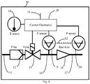
- FIG. 4 illustrates how a pressure sensor 51 may be connected purely mechanically, as shown by the dashed line 52, to the mounting of pressure sensor 15.
- Pressure sensor 51 is not fluidly connected to internal volume 14, but instead is used as a microphone for vibrations from the controller environment. Such vibrations may arise from external sources as well as directly from proportioning valve 13, and also from gas flow transient 'hammer' noises caused by valve 13's sudden closures or openings. Being mounted so that such noise in sensor 51 is similar to the noise picked up by sensor 15, the sensor 51 signal can be subtracted from that of sensor 15 to yield a more accurate pressure waveform for the internal volume 14.
- FIG. 5 shows an exemplary pressure waveform 60 from sensor 15 of the internal volume 14 during steady-state gas flow control.
- proportioning valve 13 When proportioning valve 13 is opened by a controlled amount during a rise time T rise (61) the pressure 60 rises a small amount above the average pressure P av (64).
- a high speed proportioning valve is employed to limit pressure rise so that the overall pressure fluctuation P fall (63) is small compared to P av .
- Fig. 5 is shown a relatively large pressure fluctuation for illustration purposes, larger than would be desirable if flow oscillations are to be limited. With good proportioning valve performance, low system noise, and high electronic sensitivity, P fall can be maintained at less than 1% of P av .
- Gas flow is calculated from the pressure-fall waveform shown in Fig. 5 using well-known gas laws, with adjustments to compensate for pressure and temperature being different from 'standard' temperature and pressure conditions.
- the temperature correction is applied using sensor 18, scaled to output in absolute temperature.
- the pressure readout requires further scaling as to be described.
- the flow regime used in a number of embodiments hereof spans two extremes for gas oscillation; isothermal and adiabatic.
- the calibration in practice will be intermediate, depending on oscillation frequency and the internal volume geometry.
- the isothermal approximation applies.
- the rate of pressure decay may be of the order of several seconds, yielding gas temperature stability and hence isothermal conditions.
- controller electronic control 20 should transition its calculation mode from adiabatic to isothermal as gas flow rate falls, in a fashion which depends on the configuration of internal volume 14 and the gas flow range in use.
- STP Standard Temperature and Pressure
- An isothermal pressure change DP in volume V i over time t is caused by a 'mass flow rate' Q, proportional to the number of molecules flowing per unit time [hence not strictly a mass, but rather a molecular flow rate], and also yielding the required temperature correction to flow readings due to lowered gas density as ambient temperature rises:
- Q ⁇ DP T 0 V i / P 0 Tt
- for falling pressure ⁇ T 0 / P 0 V i / T dP / dt for isothermal ' mass ' flow at STP
- MFC calibration and verification in situ may employ this formula set with an upstream valved volume with pressure regulation to permit valved volume pressure changes without sudden MFC inlet pressure variations; see US Pats. 6,363,958 (Ollivier ), 6,450,200 (Ollivier ), 7,823,436 (Monkowski et al ), 8,240,324 (Monkowski et al ), 5,394,755 (Sudo et al ).
- a downstream valved volume with a similar pressure change measurement may be used with this formula set to check flow; for example see US Pats. 7,412,986 (Tison et al ), 7,424,895 (Tison et al ), 7,975,558 (Lee et al ), 8,205,629 (Gegor et al ), US 2008/0035202 (Lee et al ), US 2010/0251828 (Lee et al ).
- This isothermal formula rather than being used merely for flow controller calibration, also forms the basis of flow sensors and controllers based upon the rate of pressure fall of a volume connected to a flow restrictor; see US Pats. 4,285,245 (Kennedy ), 6,119,710 (Brown ), 6,216,726 (Brown et al ), 4,364,413 (Bersin et al ).
- Diatomic molecule values for [1/k] are around 0.7; monatomic [1/k] values are 0.6 (see for example http://en.wikipedia.org/wiki/Heat_capacity_ratio).
- the adiabatic 'mass' flow rate Q is thus a factor of [1/k] ⁇ 2/3 of isothermal flow values; Q ⁇ 1 / k V / T dP / dt .
- the internal volume V i (14) must be emptied if a flow reduction is required. Rapid dump of this pressure may be achieved through inlet proportioning valve 13 and upstream purge valve 32, or through a separate purge valve and purge connection in the internal volume 14, if optionally provided.
- both restrictor types yield similar fall times to 1/10 of full-scale but thereafter the tubular / capillary line type falls more slowly than the choked-flow thin orifice type, yielding an advantage to orifice restrictors.
- choked-flow orifices have the competing disadvantage of lower restrictor property feedback accuracy than do tubular flow restrictors in the low-flow regime.
- orifices are usually smaller, hence more easily clogged or eroded, than are tubular restrictors.
- the highest-performance flow control will in general be attained using tubular flow restrictors combined with upstream purging of internal volume 14.
- FIG. 6 is a block diagram of Control Electronics 20 operation for the embodiment shown in Figs. 1 and 2 .
- Pressure sensor 15 signal is amplified and presented to microprocessor 70 together with temperature sensor 18's amplified output.
- the microprocessor calculates the instantaneous flow rate and thus determines any changes, if needed, to the drive required on the fast proportional valve 13, both in the length of its 'on' time T rise (61) and in valve drive power level from a Pulse Width Modulated (PWM) output from the microprocessor.
- PWM Pulse Width Modulated
- microprocessor 70 Using its continuous calculation of gas flow rate from the rate of pressure fall P fall (63) during time T fall (62), microprocessor 70 is able to adjust its drive to proportioning valve 13 such that average pressure P av (64) on signal line 71 yields the desired gas flow rate through restrictor 16 and the lines further downstream.
- FIG. 6 Other blocks shown in Fig. 6 provide further signal processing of the pressure signal; firstly with ac amplification of the pressure signal to attain a high-level waveform 72 of the P fall (60) signal without the P av (64) level included; and secondly a further-processed signal 73 yielding the value of P fall (63) directly.
- the exemplary boxes shown in Fig. 6 would vary, with some also being included in microprocessor 70's internal operations.
- the derivation of signal 73 from signal 72 would be done inside the microprocessor through its selection of time-stamped pressure values from the real-time waveform 72 at times which avoid transients due to incoming gas flow shock noise at valve on/off actuation times, followed by digital subtraction of those pressure values and digital division by their time difference to yield the rate of pressure fall.
- the microprocessor selects pressure values inside the T fall (62) period which are relatively noise-free in order to make the most accurate flow calculation.
- microprocessor 70 it is further desirable to insert an additional ac pressure input to microprocessor 70, scaled to yield a less-highly amplified pressure transient waveform than is provided on line 72 so that short-term unexpected changes in the waveform can be adequately responded to.
- an additional switched ac pressure amplification stage and an additional ADC input to the microprocessor to achieve this goal.
- a nonlinear amplification stage, with compressed gain at high input signal levels may be used either to replace the stage driving line 72, or separately from it. All of these measures, either separately or in combination, would yield the ability to respond appropriately to inlet pressure transients as will be discussed in the context of Fig. 7 .
- the pressure drop value is to be divided by T fall (62) to obtain a flow value.
- timing is controlled with extreme crystal-clock precision in the microprocessor 70, and can be assumed to not add to the above uncertainties in the final result.
- Such sources of noise on the pressure sensor 15 can be reduced through at least one of the measures of; slow opening and closing of the proportioning valve, gas flow and sonic wave damping structures in internal volume 14, positioning of pressure sensor 15 to avoid line-of-sight exposure to the direct gas flows from proportioning valve 13, and connection of sensor 15 into internal volume 14 using appropriately sized tubulation.
- the waves cannot be sufficiently damped using the above measures due to volume or response time constraints, single time-stamped pressure fall measurements may be less accurate than filtered values which compensate for this cavity resonance and other noise sources.
- Flow oscillation timing is a further important feature of gas control, and here is controlled by internal volume 14 and the desired flow rate.
- the flow rate of gas is, in sccm ('standard cubic centimeters per minute');
- Thermal gas flow sensors exhibit long-term and ambient temperature drift in zero levels which makes low flow measurement difficult. These zero levels also change with device orientation. Pressure sensor zero drift affects the average pressure reading P (71), hence the apparent flow impedance of the restrictor and downstream lines. At low flows where values of P may become comparable with pressure sensor zero drifts, faulty measures of restrictor 16 and downstream conditions will result until the system is auto-zeroed to compensate for sensor drift by recording a known pressure (preferably one close to vacuum in comparison with typical values of P (71) in use) in volume 14 at the end of a process run. Thereafter, readings of these downstream conditions will become more accurate until further uncompensated drift occurs.
- pressure sensor zero drift has no effect on gas flow rate in the devices, systems and methods hereof since zero drift has no effect on the small-signal P ac (72) oscillating waveform used for flow sensing.
- P ac (72) oscillating waveform used for flow sensing.
- the required flow for a process will be maintained at normal system accuracy independent of pressure sensor zero drift, even if it occurs during a process run.
- Sensors may however also exhibit 'span' drift, wherein their basic sensitivity is affected.
- Flow measurement in a number of embodiments of systems hereof is directly proportional to sensor span, and span drift can be compensated for exactly as zero drift is removed above, by recording a second known pressure in volume 14 at the end of a process run. The combination of two known pressure readings yields both sensor zero and span calibrations.
- devices, systems and methods hereof provide, through the above periodic checks of its pressure sensor and monitoring of its restrictor conditions, complete automated in-situ recalibration and certification of its own accuracy. Such auto-calibration is not available from thermal flow sensors or from pressure-based open-loop flow devices.
- the only factor that can affect the accuracy of controllers in a number of embodiments hereof is fouling of internal volume 14 such that its volume is reduced, resulting in a flow readout higher than the true flow, and so causing pressure P (71) to be lower than it should be for a normal restrictor16, and thus in a gas flow lower than desired.
- restrictor 16 which is of necessity a smaller diameter than internal volume 14, would foul more rapidly, requiring higher pressure than is normal for the desired flow, and thus provides early warning of later flow errors.
- the microprocessor 70 further has the capability in its internal or externally attached memory to store its auto-calibration history. Thus its record of any required compensations to original settings can be downloaded for system analysis. This record is further able to be time-stamped with an inbuilt real-time clock with battery backup and supplemental data storage. Such real-time-stamped storage capabilities are common in the industry and can be achieved either internally to the microprocessor using a battery backup power unit, or with an external real-time chip module. Such modules commonly include memory so that both time and data are recordable with full battery backup.
- the amplified pressure variation signal 72 is a measure of flow
- the basic pressure signal 71 is a measure of total line restriction
- typical data logs would include time, temperature, pressure signal 71, and the instantaneous flow request value and the resultant actual flow value. In cases where other sensors are used such as downstream pressure sensor 41, its value would also be included in the stored data.
- the microprocessor 70 can be instructed to flag any auto-calibration compensations which are outside a desired user-allocated band of acceptability. This affords early and pre-emptive maintenance warnings, while maintaining full rated flow accuracy.
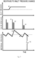
- FIG. 7 illustrates the effect of input pressure transients 80 on flow controller operations.
- inlet pressure on line 11 rises.
- the waveforms 81 and 82 impressed upon the fast proportioning valve 13 are identical.
- the initial power burst 81 of valve drive may be required to move the valve plunger off its seat in a timely fashion, and to counteract the force due to pressure differential from line 11 to internal volume 14 across the valve when it is shut.
- this high drive level would yield excessively large gas bursts into internal volume 14, so drive is reduced to level 82 for the remainder of its 'on' time T rise (61).
Landscapes
- Physics & Mathematics (AREA)
- General Physics & Mathematics (AREA)
- Fluid Mechanics (AREA)
- Engineering & Computer Science (AREA)
- Automation & Control Theory (AREA)
- Measuring Volume Flow (AREA)
- Flow Control (AREA)
Claims (15)
- Verfahren zum volumetrischen Messen und Steuern einer durchschnittlichen molekularen Gasströmungsrate von einer stromaufwärtigen Gasquelle mit einem Druck, der höher als ein Druck eines Bestimmungsortes für das Gas ist, umfassend:Strömen des Gases durch ein stromaufwärtiges Ventil (13) in einen Hohlraum (14) mit bekanntem Volumen und dann durch ein Drosselelement (16), bevor es zum Bestimmungsort voranschreitet,wobei das stromaufwärtige Ventil das einzige Ventil ist, das über die Steuerelektronik zwischen der stromaufwärtigen Gasquelle und dem Bestimmungsort für das Gas gesteuert wird, während die durchschnittliche molekulare Gasströmungsrate zum Bestimmungsort volumetrisch gemessen und gesteuert wird, wodurch die stromabwärtige Gasströmungsrate zum Bestimmungsort innerhalb prozesskompatibler Grenzen um die durchschnittliche molekulare Gasströmungsrate auf wiederholte oszillierende Weise variieren kann;Steuern des stromaufwärtigen Ventils, sodass ein durchschnittlicher Druck in dem Hohlraum mit einem durchschnittlichen Niveau der Gasströmungsrate korreliert;dadurch gekennzeichnet, dass das Verfahren zusätzlich die folgenden Schritte einschließt,Steuern des stromaufwärtigen Ventils über die Steuerelektronik (20), um die Gasströmungsrate von der stromaufwärtigen Quelle durch das stromaufwärtige Ventil in einer bestimmten oszillierenden Weise zwischen einem Zustand höherer Gasströmungsraten und einem Zustand niedrigerer Gasströmungsraten wiederholt variieren zu lassen, sodass die Gasströmungsrate durch das stromaufwärtige Ventil im Zustand niedrigerer Gasströmungsraten nicht mehr als fünf Prozent der Gasströmungsrate im Zustand höherer Gasströmungsraten beträgt;Steuern des stromaufwärtigen Ventils, sodass Druckschwankungen in dem Hohlraum, die durch Variieren der Gasströmungsrate durch das stromaufwärtige Ventil in der bestimmten Weise induziert werden, augenblickliche Druckschwankungen induzieren, die kleiner als 30 % des durchschnittlichen Drucks in dem Hohlraum sind;Überwachen einer Temperatur in dem Hohlraum unter Verwendung eines Temperaturerfassungselements, um eine Korrektur für Gasdichteänderungen zu ermöglichen; undBerechnen der molekularen Gasströmungsrate zum Bestimmungsort in Echtzeit, wenn sich das stromaufwärtige Ventil im Zustand niedrigerer Gasströmungsraten befindet, unter Verwendung einer Druckabfallrate in dem Hohlraum, um die molekulare Gasströmungsrate zum Bestimmungsort zu steuern.
- Verfahren nach Anspruch 1, wobei das Drosselelement ein Rohr mit einem Innendurchmesser umfasst, der kleiner als das 4-Fache einer Länge des Rohrs ist.
- Verfahren nach Anspruch 1, wobei das Drosselelement eine dünne Öffnungsplatte mit einer effektiven Dicke von nicht mehr als dem 4-Fachen eines Durchmessers der Öffnung umfasst.
- Verfahren nach Anspruch 1, wobei mindestens eine Eigenschaft ausgewählt aus der Gruppe, bestehend aus Gaswärmekapazitätsverhältnis, Hohlraumgeometrie und einem Bereich der Gasströmungsrate, verwendet wird, um die molekulare Gasströmungsrate als eine volumetrische Gasströmungsrate bei Standardbedingungen unter Verwendung mindestens einer von isothermen und adiabatischen Näherungen an die Hohlraumgasdynamik zu berechnen.
- Verfahren nach Anspruch 1, wobei die bestimmte molekulare Gasströmungsrate verwendet wird, um Eigenschaften des Drosselelements dynamisch zu aktualisieren, um mindestens eines der Folgenden zu verbessern; Erfassung der durchschnittlichen Gasströmungsrate, Anzeige eines beginnenden Fehlers im Drosselelement und Anzeige eines beginnenden Fehlers in einer Komponente stromabwärts des Drosselelements.
- Verfahren nach Anspruch 1, wobei der Druck in dem Hohlraum in Echtzeit sowohl in einer Bruttoform überwacht wird, um eine Brutto-Durchschnittsdruckauslesung und eine abgeleitete Durchschnittsgasströmungsauslesung zu ergeben, als auch in einer detaillierten Form, um eine detaillierte Auslesung von Druckschwankungen im Hohlraum zu ergeben, die verwendet wird, um mindestens eine der Genauigkeit der Erfassung der Gasströmungsrate, wenn sich das stromaufwärtige Ventil im Zustand niedriger Gasströmungsraten befindet, und einer schnellen Reaktion auf stromaufwärtige Gasdrucktransienten zu verbessern, wenn sich das stromaufwärtige Ventil im Zustand hoher Gasströmungsraten befindet, um dazu beizutragen, die Konstanz der stromabwärtigen Gasströmungsrate im Wesentlichen unabhängig vom Druck der stromaufwärtigen Gasquelle aufrechtzuerhalten.
- Verfahren nach Anspruch 1, wobei ein zweites Ventil (32) entweder stromaufwärts des stromaufwärtigen Ventils oder in Verbindung mit dem Hohlraum zum Anschluss an eine Niederdruckleitung vorgesehen ist, um ein schnelles Entfernen von Druck aus dem Hohlraum zu ermöglichen.
- Verfahren nach Anspruch 1, wobei die prozesskompatiblen Grenzen von stromabwärtigen Strömungsschwankungen zwischen 0,02 % und 30 % einer durchschnittlichen stromabwärtigen Strömungsrate liegen.
- Verfahren nach Anspruch 1, wobei prozesskompatible Grenzen für stromabwärtige Strömungsschwankungen zwischen 0,1 % und 10 % der durchschnittlichen stromabwärtigen Strömungsrate liegen.
- Verfahren nach Anspruch 1, wobei eine Geometrie des Hohlraums, ein Verbindungspunkt eines Drucksensors und eine Verbindungsröhre des Drucksensors konfiguriert sind, um detektierte Druckimpulstransienten zu reduzieren, die sich aus Zustandsänderungen des stromaufwärtigen Ventils ergeben.
- Verfahren nach Anspruch 1, wobei ein Druck stromabwärts des Drosselelements über einen stromabwärtigen Drucksensor (11) erfasst und eingesetzt wird, um mindestens eine der Strömungsberechnungsgenauigkeit, der Geräuschunterdrückung und der Erfassung ungeeigneter Strömungsbedingungen zu verbessern.
- Verfahren nach Anspruch 1, wobei eine periodische absolute Kalibrierung des Gasströmungssystems durch die Anwendung einer bekannten Reihe von einem oder mehreren Drücken an dem Drucksensor in operativer Verbindung mit dem Hohlraum erreicht wird, um mindestens eine seiner Nullpunkt- und Spannweiteneinstellungen zu bestimmen.
- Vorrichtung zum volumetrischen Messen und Steuern einer molekularen Gasströmungsrate von einer Gasquelle bei einem Druck, der höher als ein Druck eines Bestimmungsorts ist, umfassend: ein stromaufwärtiges Ventil (13), einen Hohlraum (14) mit bekanntem Volumen in Fluidverbindung mit dem stromaufwärtigen Ventil, ein Drosselelement (16) in Fluidverbindung mit dem stromaufwärtigen Ventil über den Hohlraum und ein Steuersystem (20), das mindestens eines von einem Prozessor oder einer anderen Art einer programmierbaren Vorrichtung umfasst,
wobei das stromaufwärtige Ventil das einzige Ventil ist, das über das Steuersystem zwischen der stromaufwärtigen Gasquelle und dem Bestimmungsort für das Gas gesteuert wird, um die durchschnittliche molekulare Gasströmungsrate zum Bestimmungsort volumetrisch zu messen und zu steuern, wodurch die molekulare Gasströmungsrate zum Bestimmungsort innerhalb prozesskompatibler Grenzen um die durchschnittliche molekulare Gasströmungsrate auf oszillierende Weise variieren kann,
dadurch gekennzeichnet, dass
das Steuersystem angepasst ist, um die Gasströmungsrate durch das stromaufwärtige Ventil wiederholt auf bestimmte Weise variieren zu lassen, sodass ein durchschnittlicher Druck in dem Hohlraum verwendet wird, um die Gasströmungsrate zu überwachen, und sodass Druckschwankungen in dem Hohlraum, die durch das Variieren der Gasströmungsrate durch das stromaufwärtige Ventil auf bestimmte Weise induziert werden, augenblickliche Strömungsschwankungen induzieren, die kleiner als 30 % eines durchschnittlichen Niveaus der Gasströmungsrate zum Bestimmungsort sind, wobei Druckschwankungen in dem Hohlraum, die mit dem Variieren der Gasströmungsrate durch das stromaufwärtige Ventil auf die bestimmte Weise assoziiert sind, vom Prozessor oder einer anderen Art einer programmierbaren Vorrichtung verwendet werden, um die durchschnittliche molekulare Gasströmungsrate während wiederholter oszillierender Schwankungen der Gasströmungsrate zum Bestimmungsort in Echtzeit volumetrisch zu messen und zu steuern. - System, umfassend einen Strömungsweg für ein Gas von einer Gasquelle zu einem Bestimmungsort, wobei das System eine Vorrichtung nach Anspruch 13 umfasst.
- System nach Anspruch 14, wobei das System ferner eine Verarbeitungskammer (34) stromabwärts der Vorrichtung umfasst, die zur Verwendung bei der Herstellung von Computerchips angepasst ist.
Applications Claiming Priority (2)
| Application Number | Priority Date | Filing Date | Title |
|---|---|---|---|
| US201361785235P | 2013-03-14 | 2013-03-14 | |
| PCT/US2014/027698 WO2014152755A2 (en) | 2013-03-14 | 2014-03-14 | Pressure-based gas flow controller with dynamic self-calibration |
Publications (3)
| Publication Number | Publication Date |
|---|---|
| EP3036510A2 EP3036510A2 (de) | 2016-06-29 |
| EP3036510A4 EP3036510A4 (de) | 2017-06-07 |
| EP3036510B1 true EP3036510B1 (de) | 2021-06-09 |
Family
ID=51581743
Family Applications (1)
| Application Number | Title | Priority Date | Filing Date |
|---|---|---|---|
| EP14769464.0A Active EP3036510B1 (de) | 2013-03-14 | 2014-03-14 | Druckbasierte gasströmungssteuerung mit dynamischer selbstkalibrierung |
Country Status (3)
| Country | Link |
|---|---|
| US (1) | US9910448B2 (de) |
| EP (1) | EP3036510B1 (de) |
| WO (1) | WO2014152755A2 (de) |
Families Citing this family (31)
| Publication number | Priority date | Publication date | Assignee | Title |
|---|---|---|---|---|
| US20160041564A1 (en) * | 2012-08-20 | 2016-02-11 | Daniel T. Mudd | Reverse flow mode for regulating pressure of an accumulated volume with fast upstream bleed down |
| US9910448B2 (en) | 2013-03-14 | 2018-03-06 | Christopher Max Horwitz | Pressure-based gas flow controller with dynamic self-calibration |
| WO2017040100A1 (en) * | 2015-08-31 | 2017-03-09 | Mks Instruments, Inc. | Method and apparatus for pressure-based flow measurement in non-critical flow conditions |
| US10684159B2 (en) * | 2016-06-27 | 2020-06-16 | Applied Materials, Inc. | Methods, systems, and apparatus for mass flow verification based on choked flow |
| US11144075B2 (en) | 2016-06-30 | 2021-10-12 | Ichor Systems, Inc. | Flow control system, method, and apparatus |
| US10838437B2 (en) | 2018-02-22 | 2020-11-17 | Ichor Systems, Inc. | Apparatus for splitting flow of process gas and method of operating same |
| US20180046206A1 (en) * | 2016-08-13 | 2018-02-15 | Applied Materials, Inc. | Method and apparatus for controlling gas flow to a process chamber |
| JP6762218B2 (ja) * | 2016-12-13 | 2020-09-30 | 株式会社堀場エステック | 流量算出システム及び流量算出方法 |
| US10983537B2 (en) * | 2017-02-27 | 2021-04-20 | Flow Devices And Systems Inc. | Systems and methods for flow sensor back pressure adjustment for mass flow controller |
| CN111148973B (zh) * | 2017-07-31 | 2023-06-13 | 喷雾系统公司 | 改进的喷雾监测的装置和方法 |
| WO2019065611A1 (ja) * | 2017-09-29 | 2019-04-04 | 日立金属株式会社 | 質量流量制御システム並びに当該システムを含む半導体製造装置及び気化器 |
| JP6841201B2 (ja) * | 2017-10-06 | 2021-03-10 | 株式会社島津製作所 | ガス推定装置および真空排気装置 |
| WO2019084339A1 (en) * | 2017-10-25 | 2019-05-02 | Flow Devices And Systems Inc. | WIDE RANGE FLOW REGULATOR WITH LOW RATE OF FLOW DECREE AND TEMPERATURE DETERMINATION |
| US11675374B2 (en) * | 2018-10-26 | 2023-06-13 | Illinois Tool Works Inc. | Mass flow controller with advanced zero trending diagnostics |
| US12379238B2 (en) | 2018-10-26 | 2025-08-05 | Illinois Tool Works Inc. | Mass flow controller with advanced back streaming diagnostics |
| EP3838411A1 (de) * | 2019-12-18 | 2021-06-23 | TECAN Trading AG | Pipettiervorrichtung und -verfahren |
| CN111044125B (zh) * | 2019-12-31 | 2021-10-15 | 华东理工大学 | 流量点自动标定的方法及存储介质 |
| EP3882737B1 (de) * | 2020-03-20 | 2022-04-27 | Siemens Aktiengesellschaft | Fluiddrucksteuervorrichtung |
| EP4135815B1 (de) * | 2020-04-15 | 2025-07-09 | Christopher Max Horwitz | Hochleistungs- und kostengünstige medizinische atemgasabgabesysteme |
| CN112229663B (zh) * | 2020-10-13 | 2023-01-10 | 国家电投集团重庆合川发电有限公司 | 空预器漏风率在线确定方法、装置、设备及存储介质 |
| CN114577396A (zh) * | 2020-11-30 | 2022-06-03 | 福迪威(上海)工业仪器技术研发有限公司 | 一种压力检测装置 |
| WO2022186971A1 (en) | 2021-03-03 | 2022-09-09 | Ichor Systems, Inc. | Fluid flow control system comprising a manifold assembly |
| DE102021203217A1 (de) * | 2021-03-30 | 2022-03-24 | Vitesco Technologies GmbH | Luftmassensensor und Kraftfahrzeug |
| CN113374949A (zh) * | 2021-05-20 | 2021-09-10 | 广西电网有限责任公司电力科学研究院 | 一种质量流量控制器 |
| US12434958B2 (en) | 2021-05-26 | 2025-10-07 | Eugster / Frismag Ag | Metering device for adjusting and/or controlling a gas flow, method for adjusting and/or controlling a gas flow, and domestic appliance assembly |
| JP7713225B2 (ja) * | 2021-07-27 | 2025-07-25 | 株式会社フジキン | 圧力式流量制御装置 |
| CN115950493B (zh) * | 2022-12-21 | 2024-06-07 | 南京航空航天大学 | 一种适用于亚声速流道的流量测试系统及测试方法 |
| DE202022107233U1 (de) * | 2022-12-23 | 2023-01-23 | Innovative Sensor Technology Ist Ag | Thermisches Durchflussmessgerät mit automatischer Gaserkennung |
| US12366869B2 (en) * | 2023-03-13 | 2025-07-22 | Robertshaw Controls Company | Pressure sensing valve |
| CN119914831B (zh) * | 2023-10-31 | 2025-11-07 | 中国石油天然气股份有限公司 | 调压装置及其保养方法 |
| CN119465092B (zh) * | 2024-11-08 | 2026-02-17 | 研微(江苏)半导体科技有限公司 | 用于半导体反应腔的进气系统及其离散控制方法 |
Family Cites Families (35)
| Publication number | Priority date | Publication date | Assignee | Title |
|---|---|---|---|---|
| DE2928739C2 (de) * | 1979-07-17 | 1981-03-19 | Ruhrgas Ag, 4300 Essen | Verfahren und Vorrichtung zur verbrennungslosen Messung und/oder Regelung der Wärmemengenzufuhr zu Gasverbrauchseinrichtungen |
| US4285245A (en) * | 1979-12-06 | 1981-08-25 | Precision Machine Products, Inc. | Method and apparatus for measuring and controlling volumetric flow rate of gases in a line |
| US4364413A (en) | 1981-01-07 | 1982-12-21 | The Perkin-Elmer Corporation | Molar gas-flow controller |
| US5062446A (en) * | 1991-01-07 | 1991-11-05 | Sematech, Inc. | Intelligent mass flow controller |
| JP2692770B2 (ja) | 1992-09-30 | 1997-12-17 | シーケーディ株式会社 | マスフローコントローラ流量検定システム |
| AU1678595A (en) | 1994-01-14 | 1995-08-01 | Unit Instruments, Inc. | Flow meter |
| US5868159A (en) | 1996-07-12 | 1999-02-09 | Mks Instruments, Inc. | Pressure-based mass flow controller |
| US5865205A (en) * | 1997-04-17 | 1999-02-02 | Applied Materials, Inc. | Dynamic gas flow controller |
| JP3932389B2 (ja) * | 1998-01-19 | 2007-06-20 | Smc株式会社 | マスフローコントローラの自己診断方法 |
| US6026849A (en) | 1998-06-01 | 2000-02-22 | Thordarson; Petur | High pressure regulated flow controller |
| US6363958B1 (en) | 1999-05-10 | 2002-04-02 | Parker-Hannifin Corporation | Flow control of process gas in semiconductor manufacturing |
| US6119710A (en) | 1999-05-26 | 2000-09-19 | Cyber Instrument Technologies Llc | Method for wide range gas flow system with real time flow measurement and correction |
| US6631334B2 (en) | 2000-12-26 | 2003-10-07 | Mks Instruments, Inc. | Pressure-based mass flow controller system |
| US6564824B2 (en) * | 2001-04-13 | 2003-05-20 | Flowmatrix, Inc. | Mass flow meter systems and methods |
| US6962164B2 (en) | 2001-04-24 | 2005-11-08 | Celerity Group, Inc. | System and method for a mass flow controller |
| US7809473B2 (en) | 2002-06-24 | 2010-10-05 | Mks Instruments, Inc. | Apparatus and method for pressure fluctuation insensitive mass flow control |
| US6712084B2 (en) | 2002-06-24 | 2004-03-30 | Mks Instruments, Inc. | Apparatus and method for pressure fluctuation insensitive mass flow control |
| JP4020016B2 (ja) * | 2003-05-28 | 2007-12-12 | 株式会社島津製作所 | ガスクロマトグラフ |
| JP4204400B2 (ja) * | 2003-07-03 | 2009-01-07 | 忠弘 大見 | 差圧式流量計及び差圧式流量制御装置 |
| US7412986B2 (en) | 2004-07-09 | 2008-08-19 | Celerity, Inc. | Method and system for flow measurement and validation of a mass flow controller |
| US7107834B2 (en) | 2004-11-12 | 2006-09-19 | Mks Instruments, Inc. | Thermal mass flow rate sensor including bypass passageways and a sensor passageway having similar entrance effects |
| US7225085B2 (en) | 2005-02-25 | 2007-05-29 | The Regents Of The University Of California | Precision gas flow meter |
| US7243538B1 (en) | 2005-12-22 | 2007-07-17 | Honeywell International Inc. | Gas flow sensor system and method of self-calibration |
| US7743670B2 (en) | 2006-08-14 | 2010-06-29 | Applied Materials, Inc. | Method and apparatus for gas flow measurement |
| TW200834275A (en) | 2006-09-05 | 2008-08-16 | Celerity Inc | Multi-gas flow device |
| US7623975B2 (en) * | 2007-05-30 | 2009-11-24 | zed.i solutions Inc. | Method of measuring gas flow |
| EP2055918B1 (de) * | 2007-10-31 | 2016-06-01 | Fiat Group Automobiles S.p.A. | Verfahren und Vorrichtung zum Schätzen der Ansaugluftmenge bei einem Verbrennungsmotor |
| EP2247819B1 (de) | 2008-01-18 | 2022-11-02 | Pivotal Systems Corporation | Verfahren und vorrichtung für die vorortprüfung von gasströmungssteuerungen |
| US8205629B2 (en) | 2008-04-25 | 2012-06-26 | Applied Materials, Inc. | Real time lead-line characterization for MFC flow verification |
| US8265795B2 (en) | 2009-11-05 | 2012-09-11 | Horiba Stec, Co., Ltd. | Mass flow controller |
| US9389111B2 (en) * | 2010-03-11 | 2016-07-12 | Measurement Technology Group, Inc. | Dynamic-adaptive vapor reduction system and method |
| US9400004B2 (en) * | 2010-11-29 | 2016-07-26 | Pivotal Systems Corporation | Transient measurements of mass flow controllers |
| US9471066B2 (en) * | 2012-01-20 | 2016-10-18 | Mks Instruments, Inc. | System for and method of providing pressure insensitive self verifying mass flow controller |
| US9739655B2 (en) * | 2012-03-07 | 2017-08-22 | Illinois Tool Works Inc. | System and method for using a rate of decay measurement for real time measurement and correction of zero offset and zero drift of a mass flow controller or mass flow meter |
| US9910448B2 (en) | 2013-03-14 | 2018-03-06 | Christopher Max Horwitz | Pressure-based gas flow controller with dynamic self-calibration |
-
2014
- 2014-03-14 US US14/345,275 patent/US9910448B2/en active Active
- 2014-03-14 WO PCT/US2014/027698 patent/WO2014152755A2/en not_active Ceased
- 2014-03-14 EP EP14769464.0A patent/EP3036510B1/de active Active
Non-Patent Citations (1)
| Title |
|---|
| None * |
Also Published As
| Publication number | Publication date |
|---|---|
| WO2014152755A2 (en) | 2014-09-25 |
| WO2014152755A3 (en) | 2014-12-31 |
| US9910448B2 (en) | 2018-03-06 |
| EP3036510A2 (de) | 2016-06-29 |
| US20160252912A1 (en) | 2016-09-01 |
| EP3036510A4 (de) | 2017-06-07 |
Similar Documents
| Publication | Publication Date | Title |
|---|---|---|
| EP3036510B1 (de) | Druckbasierte gasströmungssteuerung mit dynamischer selbstkalibrierung | |
| US7905139B2 (en) | Mass flow controller with improved dynamic | |
| US9797765B2 (en) | Self-calibrating mechanism and self-calibrating method for flow rate sensor, and diagnostic mechanism and diagnostic method for fluid sensor | |
| KR101572407B1 (ko) | 차압식 매스 플로우 컨트롤러에 있어서 진단 기구 | |
| EP2901227B1 (de) | Verfahren und vorrichtung zur selbstüberprüfung von druckbasierten masseflussreglern | |
| JP3863505B2 (ja) | 圧力センサ及び圧力制御装置並びに圧力式流量制御装置の自動零点補正装置 | |
| US7216019B2 (en) | Method and system for a mass flow controller with reduced pressure sensitivity | |
| CN101636641B (zh) | 用于质量流量控制器的控制器增益调度 | |
| JP6064599B2 (ja) | ガス・フロー制御のための方法及び装置 | |
| KR101840047B1 (ko) | 가스 유동 제어기의 인 시투 시험을 위한 방법 및 장치 | |
| US20090078055A1 (en) | Methods and apparatus for pressure compensation in a mass flow controller | |
| KR20010052885A (ko) | 병렬분류형 유체공급장치와, 이것에 사용하는 유체가변형압력식 유량제어방법 및 유체가변형 압력식 유량제어장치 | |
| JP2016531299A (ja) | 絶対圧差圧圧力トランスデューサー | |
| JP2010216807A (ja) | マスフローメータ、マスフローコントローラ、それらを含むマスフローメータシステムおよびマスフローコントローラシステム | |
| CN106233061A (zh) | 用于实时监测穿过质量流量控制器的流量的系统以及方法 | |
| JPWO2019107216A1 (ja) | 流量制御装置の自己診断方法 | |
| JP7752036B2 (ja) | 流量制御装置、流量制御方法、及び、流量制御装置用プログラム | |
| US12287655B2 (en) | Method and apparatus for mass flow control | |
| JP7244940B2 (ja) | 流量制御システム及び流量測定方法 | |
| CN101178327A (zh) | 气体流量校准的方法 | |
| US11550341B2 (en) | Mass flow control system, and semiconductor manufacturing equipment and vaporizer including the system | |
| WO2025038383A1 (en) | Method and apparatus for automatic self calibration of mass flow controller | |
| JP7249030B2 (ja) | 流量測定装置内の容積測定方法および流量測定装置 | |
| US12393209B2 (en) | Methods and apparatus for reporting inlet pressure in mass flow controllers | |
| GB2372331A (en) | A mechanism for in situ calibration of pressure sensors in plasma processing systems |
Legal Events
| Date | Code | Title | Description |
|---|---|---|---|
| PUAI | Public reference made under article 153(3) epc to a published international application that has entered the european phase |
Free format text: ORIGINAL CODE: 0009012 |
|
| 17P | Request for examination filed |
Effective date: 20160119 |
|
| AK | Designated contracting states |
Kind code of ref document: A2 Designated state(s): AL AT BE BG CH CY CZ DE DK EE ES FI FR GB GR HR HU IE IS IT LI LT LU LV MC MK MT NL NO PL PT RO RS SE SI SK SM TR |
|
| A4 | Supplementary search report drawn up and despatched |
Effective date: 20170511 |
|
| RIC1 | Information provided on ipc code assigned before grant |
Ipc: G05D 7/06 20060101ALI20170504BHEP Ipc: G01F 1/00 20060101AFI20170504BHEP Ipc: G01F 25/00 20060101ALI20170504BHEP Ipc: E03B 1/00 20060101ALI20170504BHEP |
|
| STAA | Information on the status of an ep patent application or granted ep patent |
Free format text: STATUS: EXAMINATION IS IN PROGRESS |
|
| 17Q | First examination report despatched |
Effective date: 20200224 |
|
| GRAP | Despatch of communication of intention to grant a patent |
Free format text: ORIGINAL CODE: EPIDOSNIGR1 |
|
| STAA | Information on the status of an ep patent application or granted ep patent |
Free format text: STATUS: GRANT OF PATENT IS INTENDED |
|
| INTG | Intention to grant announced |
Effective date: 20201221 |
|
| GRAS | Grant fee paid |
Free format text: ORIGINAL CODE: EPIDOSNIGR3 |
|
| GRAA | (expected) grant |
Free format text: ORIGINAL CODE: 0009210 |
|
| STAA | Information on the status of an ep patent application or granted ep patent |
Free format text: STATUS: THE PATENT HAS BEEN GRANTED |
|
| AK | Designated contracting states |
Kind code of ref document: B1 Designated state(s): AL AT BE BG CH CY CZ DE DK EE ES FI FR GB GR HR HU IE IS IT LI LT LU LV MC MK MT NL NO PL PT RO RS SE SI SK SM TR |
|
| REG | Reference to a national code |
Ref country code: GB Ref legal event code: FG4D |
|
| REG | Reference to a national code |
Ref country code: CH Ref legal event code: EP Ref country code: AT Ref legal event code: REF Ref document number: 1400889 Country of ref document: AT Kind code of ref document: T Effective date: 20210615 |
|
| REG | Reference to a national code |
Ref country code: DE Ref legal event code: R096 Ref document number: 602014078025 Country of ref document: DE |
|
| REG | Reference to a national code |
Ref country code: IE Ref legal event code: FG4D |
|
| REG | Reference to a national code |
Ref country code: LT Ref legal event code: MG9D |
|
| PG25 | Lapsed in a contracting state [announced via postgrant information from national office to epo] |
Ref country code: BG Free format text: LAPSE BECAUSE OF FAILURE TO SUBMIT A TRANSLATION OF THE DESCRIPTION OR TO PAY THE FEE WITHIN THE PRESCRIBED TIME-LIMIT Effective date: 20210909 Ref country code: FI Free format text: LAPSE BECAUSE OF FAILURE TO SUBMIT A TRANSLATION OF THE DESCRIPTION OR TO PAY THE FEE WITHIN THE PRESCRIBED TIME-LIMIT Effective date: 20210609 Ref country code: LT Free format text: LAPSE BECAUSE OF FAILURE TO SUBMIT A TRANSLATION OF THE DESCRIPTION OR TO PAY THE FEE WITHIN THE PRESCRIBED TIME-LIMIT Effective date: 20210609 Ref country code: HR Free format text: LAPSE BECAUSE OF FAILURE TO SUBMIT A TRANSLATION OF THE DESCRIPTION OR TO PAY THE FEE WITHIN THE PRESCRIBED TIME-LIMIT Effective date: 20210609 |
|
| REG | Reference to a national code |
Ref country code: AT Ref legal event code: MK05 Ref document number: 1400889 Country of ref document: AT Kind code of ref document: T Effective date: 20210609 |
|
| REG | Reference to a national code |
Ref country code: NL Ref legal event code: MP Effective date: 20210609 |
|
| PG25 | Lapsed in a contracting state [announced via postgrant information from national office to epo] |
Ref country code: LV Free format text: LAPSE BECAUSE OF FAILURE TO SUBMIT A TRANSLATION OF THE DESCRIPTION OR TO PAY THE FEE WITHIN THE PRESCRIBED TIME-LIMIT Effective date: 20210609 Ref country code: GR Free format text: LAPSE BECAUSE OF FAILURE TO SUBMIT A TRANSLATION OF THE DESCRIPTION OR TO PAY THE FEE WITHIN THE PRESCRIBED TIME-LIMIT Effective date: 20210910 Ref country code: NO Free format text: LAPSE BECAUSE OF FAILURE TO SUBMIT A TRANSLATION OF THE DESCRIPTION OR TO PAY THE FEE WITHIN THE PRESCRIBED TIME-LIMIT Effective date: 20210909 Ref country code: SE Free format text: LAPSE BECAUSE OF FAILURE TO SUBMIT A TRANSLATION OF THE DESCRIPTION OR TO PAY THE FEE WITHIN THE PRESCRIBED TIME-LIMIT Effective date: 20210609 Ref country code: RS Free format text: LAPSE BECAUSE OF FAILURE TO SUBMIT A TRANSLATION OF THE DESCRIPTION OR TO PAY THE FEE WITHIN THE PRESCRIBED TIME-LIMIT Effective date: 20210609 |
|
| PG25 | Lapsed in a contracting state [announced via postgrant information from national office to epo] |
Ref country code: EE Free format text: LAPSE BECAUSE OF FAILURE TO SUBMIT A TRANSLATION OF THE DESCRIPTION OR TO PAY THE FEE WITHIN THE PRESCRIBED TIME-LIMIT Effective date: 20210609 Ref country code: CZ Free format text: LAPSE BECAUSE OF FAILURE TO SUBMIT A TRANSLATION OF THE DESCRIPTION OR TO PAY THE FEE WITHIN THE PRESCRIBED TIME-LIMIT Effective date: 20210609 Ref country code: SM Free format text: LAPSE BECAUSE OF FAILURE TO SUBMIT A TRANSLATION OF THE DESCRIPTION OR TO PAY THE FEE WITHIN THE PRESCRIBED TIME-LIMIT Effective date: 20210609 Ref country code: SK Free format text: LAPSE BECAUSE OF FAILURE TO SUBMIT A TRANSLATION OF THE DESCRIPTION OR TO PAY THE FEE WITHIN THE PRESCRIBED TIME-LIMIT Effective date: 20210609 Ref country code: NL Free format text: LAPSE BECAUSE OF FAILURE TO SUBMIT A TRANSLATION OF THE DESCRIPTION OR TO PAY THE FEE WITHIN THE PRESCRIBED TIME-LIMIT Effective date: 20210609 Ref country code: PT Free format text: LAPSE BECAUSE OF FAILURE TO SUBMIT A TRANSLATION OF THE DESCRIPTION OR TO PAY THE FEE WITHIN THE PRESCRIBED TIME-LIMIT Effective date: 20211011 Ref country code: RO Free format text: LAPSE BECAUSE OF FAILURE TO SUBMIT A TRANSLATION OF THE DESCRIPTION OR TO PAY THE FEE WITHIN THE PRESCRIBED TIME-LIMIT Effective date: 20210609 Ref country code: ES Free format text: LAPSE BECAUSE OF FAILURE TO SUBMIT A TRANSLATION OF THE DESCRIPTION OR TO PAY THE FEE WITHIN THE PRESCRIBED TIME-LIMIT Effective date: 20210609 Ref country code: AT Free format text: LAPSE BECAUSE OF FAILURE TO SUBMIT A TRANSLATION OF THE DESCRIPTION OR TO PAY THE FEE WITHIN THE PRESCRIBED TIME-LIMIT Effective date: 20210609 |
|
| PG25 | Lapsed in a contracting state [announced via postgrant information from national office to epo] |
Ref country code: PL Free format text: LAPSE BECAUSE OF FAILURE TO SUBMIT A TRANSLATION OF THE DESCRIPTION OR TO PAY THE FEE WITHIN THE PRESCRIBED TIME-LIMIT Effective date: 20210609 |
|
| REG | Reference to a national code |
Ref country code: DE Ref legal event code: R097 Ref document number: 602014078025 Country of ref document: DE |
|
| PLBE | No opposition filed within time limit |
Free format text: ORIGINAL CODE: 0009261 |
|
| STAA | Information on the status of an ep patent application or granted ep patent |
Free format text: STATUS: NO OPPOSITION FILED WITHIN TIME LIMIT |
|
| PG25 | Lapsed in a contracting state [announced via postgrant information from national office to epo] |
Ref country code: DK Free format text: LAPSE BECAUSE OF FAILURE TO SUBMIT A TRANSLATION OF THE DESCRIPTION OR TO PAY THE FEE WITHIN THE PRESCRIBED TIME-LIMIT Effective date: 20210609 |
|
| 26N | No opposition filed |
Effective date: 20220310 |
|
| PG25 | Lapsed in a contracting state [announced via postgrant information from national office to epo] |
Ref country code: AL Free format text: LAPSE BECAUSE OF FAILURE TO SUBMIT A TRANSLATION OF THE DESCRIPTION OR TO PAY THE FEE WITHIN THE PRESCRIBED TIME-LIMIT Effective date: 20210609 |
|
| PG25 | Lapsed in a contracting state [announced via postgrant information from national office to epo] |
Ref country code: IT Free format text: LAPSE BECAUSE OF FAILURE TO SUBMIT A TRANSLATION OF THE DESCRIPTION OR TO PAY THE FEE WITHIN THE PRESCRIBED TIME-LIMIT Effective date: 20210609 |
|
| PG25 | Lapsed in a contracting state [announced via postgrant information from national office to epo] |
Ref country code: MC Free format text: LAPSE BECAUSE OF FAILURE TO SUBMIT A TRANSLATION OF THE DESCRIPTION OR TO PAY THE FEE WITHIN THE PRESCRIBED TIME-LIMIT Effective date: 20210609 |
|
| PG25 | Lapsed in a contracting state [announced via postgrant information from national office to epo] |
Ref country code: LU Free format text: LAPSE BECAUSE OF NON-PAYMENT OF DUE FEES Effective date: 20220314 Ref country code: IE Free format text: LAPSE BECAUSE OF NON-PAYMENT OF DUE FEES Effective date: 20220314 |
|
| P01 | Opt-out of the competence of the unified patent court (upc) registered |
Effective date: 20230524 |
|
| PG25 | Lapsed in a contracting state [announced via postgrant information from national office to epo] |
Ref country code: HU Free format text: LAPSE BECAUSE OF FAILURE TO SUBMIT A TRANSLATION OF THE DESCRIPTION OR TO PAY THE FEE WITHIN THE PRESCRIBED TIME-LIMIT; INVALID AB INITIO Effective date: 20140314 |
|
| PG25 | Lapsed in a contracting state [announced via postgrant information from national office to epo] |
Ref country code: MK Free format text: LAPSE BECAUSE OF FAILURE TO SUBMIT A TRANSLATION OF THE DESCRIPTION OR TO PAY THE FEE WITHIN THE PRESCRIBED TIME-LIMIT Effective date: 20210609 Ref country code: CY Free format text: LAPSE BECAUSE OF FAILURE TO SUBMIT A TRANSLATION OF THE DESCRIPTION OR TO PAY THE FEE WITHIN THE PRESCRIBED TIME-LIMIT Effective date: 20210609 |
|
| PG25 | Lapsed in a contracting state [announced via postgrant information from national office to epo] |
Ref country code: MT Free format text: LAPSE BECAUSE OF FAILURE TO SUBMIT A TRANSLATION OF THE DESCRIPTION OR TO PAY THE FEE WITHIN THE PRESCRIBED TIME-LIMIT Effective date: 20210609 |
|
| PGFP | Annual fee paid to national office [announced via postgrant information from national office to epo] |
Ref country code: CH Payment date: 20250401 Year of fee payment: 12 |
|
| PG25 | Lapsed in a contracting state [announced via postgrant information from national office to epo] |
Ref country code: TR Free format text: LAPSE BECAUSE OF FAILURE TO SUBMIT A TRANSLATION OF THE DESCRIPTION OR TO PAY THE FEE WITHIN THE PRESCRIBED TIME-LIMIT Effective date: 20210609 |
|
| REG | Reference to a national code |
Ref country code: CH Ref legal event code: U11 Free format text: ST27 STATUS EVENT CODE: U-0-0-U10-U11 (AS PROVIDED BY THE NATIONAL OFFICE) Effective date: 20260401 |
|
| PGFP | Annual fee paid to national office [announced via postgrant information from national office to epo] |
Ref country code: GB Payment date: 20260324 Year of fee payment: 13 |
|
| PGFP | Annual fee paid to national office [announced via postgrant information from national office to epo] |
Ref country code: DE Payment date: 20260319 Year of fee payment: 13 |
|
| PGFP | Annual fee paid to national office [announced via postgrant information from national office to epo] |
Ref country code: BE Payment date: 20260319 Year of fee payment: 13 |
|
| PGFP | Annual fee paid to national office [announced via postgrant information from national office to epo] |
Ref country code: FR Payment date: 20260320 Year of fee payment: 13 |