EP3036683B1 - Détection et sélection de carte à puce intelligente sans fil - Google Patents
Détection et sélection de carte à puce intelligente sans fil Download PDFInfo
- Publication number
- EP3036683B1 EP3036683B1 EP14758759.6A EP14758759A EP3036683B1 EP 3036683 B1 EP3036683 B1 EP 3036683B1 EP 14758759 A EP14758759 A EP 14758759A EP 3036683 B1 EP3036683 B1 EP 3036683B1
- Authority
- EP
- European Patent Office
- Prior art keywords
- csc
- field
- reader
- polling signal
- transmitting
- Prior art date
- Legal status (The legal status is an assumption and is not a legal conclusion. Google has not performed a legal analysis and makes no representation as to the accuracy of the status listed.)
- Active
Links
Images



Classifications
-
- G—PHYSICS
- G06—COMPUTING OR CALCULATING; COUNTING
- G06K—GRAPHICAL DATA READING; PRESENTATION OF DATA; RECORD CARRIERS; HANDLING RECORD CARRIERS
- G06K7/00—Methods or arrangements for sensing record carriers, e.g. for reading patterns
- G06K7/10—Methods or arrangements for sensing record carriers, e.g. for reading patterns by electromagnetic radiation, e.g. optical sensing; by corpuscular radiation
- G06K7/10009—Methods or arrangements for sensing record carriers, e.g. for reading patterns by electromagnetic radiation, e.g. optical sensing; by corpuscular radiation sensing by radiation using wavelengths larger than 0.1 mm, e.g. radio-waves or microwaves
- G06K7/10019—Methods or arrangements for sensing record carriers, e.g. for reading patterns by electromagnetic radiation, e.g. optical sensing; by corpuscular radiation sensing by radiation using wavelengths larger than 0.1 mm, e.g. radio-waves or microwaves resolving collision on the communication channels between simultaneously or concurrently interrogated record carriers.
- G06K7/10029—Methods or arrangements for sensing record carriers, e.g. for reading patterns by electromagnetic radiation, e.g. optical sensing; by corpuscular radiation sensing by radiation using wavelengths larger than 0.1 mm, e.g. radio-waves or microwaves resolving collision on the communication channels between simultaneously or concurrently interrogated record carriers. the collision being resolved in the time domain, e.g. using binary tree search or RFID responses allocated to a random time slot
- G06K7/10039—Methods or arrangements for sensing record carriers, e.g. for reading patterns by electromagnetic radiation, e.g. optical sensing; by corpuscular radiation sensing by radiation using wavelengths larger than 0.1 mm, e.g. radio-waves or microwaves resolving collision on the communication channels between simultaneously or concurrently interrogated record carriers. the collision being resolved in the time domain, e.g. using binary tree search or RFID responses allocated to a random time slot interrogator driven, i.e. synchronous
-
- G—PHYSICS
- G06—COMPUTING OR CALCULATING; COUNTING
- G06K—GRAPHICAL DATA READING; PRESENTATION OF DATA; RECORD CARRIERS; HANDLING RECORD CARRIERS
- G06K7/00—Methods or arrangements for sensing record carriers, e.g. for reading patterns
- G06K7/10—Methods or arrangements for sensing record carriers, e.g. for reading patterns by electromagnetic radiation, e.g. optical sensing; by corpuscular radiation
- G06K7/10009—Methods or arrangements for sensing record carriers, e.g. for reading patterns by electromagnetic radiation, e.g. optical sensing; by corpuscular radiation sensing by radiation using wavelengths larger than 0.1 mm, e.g. radio-waves or microwaves
- G06K7/10019—Methods or arrangements for sensing record carriers, e.g. for reading patterns by electromagnetic radiation, e.g. optical sensing; by corpuscular radiation sensing by radiation using wavelengths larger than 0.1 mm, e.g. radio-waves or microwaves resolving collision on the communication channels between simultaneously or concurrently interrogated record carriers.
- G06K7/10079—Methods or arrangements for sensing record carriers, e.g. for reading patterns by electromagnetic radiation, e.g. optical sensing; by corpuscular radiation sensing by radiation using wavelengths larger than 0.1 mm, e.g. radio-waves or microwaves resolving collision on the communication channels between simultaneously or concurrently interrogated record carriers. the collision being resolved in the spatial domain, e.g. temporary shields for blindfolding the interrogator in specific directions
-
- G—PHYSICS
- G06—COMPUTING OR CALCULATING; COUNTING
- G06K—GRAPHICAL DATA READING; PRESENTATION OF DATA; RECORD CARRIERS; HANDLING RECORD CARRIERS
- G06K7/00—Methods or arrangements for sensing record carriers, e.g. for reading patterns
- G06K7/10—Methods or arrangements for sensing record carriers, e.g. for reading patterns by electromagnetic radiation, e.g. optical sensing; by corpuscular radiation
- G06K7/10009—Methods or arrangements for sensing record carriers, e.g. for reading patterns by electromagnetic radiation, e.g. optical sensing; by corpuscular radiation sensing by radiation using wavelengths larger than 0.1 mm, e.g. radio-waves or microwaves
- G06K7/10198—Methods or arrangements for sensing record carriers, e.g. for reading patterns by electromagnetic radiation, e.g. optical sensing; by corpuscular radiation sensing by radiation using wavelengths larger than 0.1 mm, e.g. radio-waves or microwaves setting parameters for the interrogator, e.g. programming parameters and operating modes
- G06K7/10217—Methods or arrangements for sensing record carriers, e.g. for reading patterns by electromagnetic radiation, e.g. optical sensing; by corpuscular radiation sensing by radiation using wavelengths larger than 0.1 mm, e.g. radio-waves or microwaves setting parameters for the interrogator, e.g. programming parameters and operating modes parameter settings controlling the transmission power of the interrogator
Definitions
- the present invention generally relates to contactless smart card readers and contactless smart cards. More specifically, the present invention relates to detection of multiple contactless smart cards and selection of a subset of the multiple contactless smart cards by contactless smart card readers.
- CSCs Contactless smart cards
- RF radio frequency
- the CSC reader can provide power to the CSC and establish communication.
- a CSC communicates with a CSC reader wirelessly using RF signals. Communication between the CSC and the CSC reader can be established through most materials, allowing a user to complete a transaction without having to remove the CSC from a wallet or pocket.
- CSCs can be utilized to identify the user, authenticate the user, or store data for the user.
- WO2006/083493A2 discloses a Contactless Smart Card (CSC) reader implementing a method for CSC detection and selection, the method comprising: generating a radio frequency "RF" field that defines a range of communication for the CSC reader; transmitting a first polling signal in the RF field; detecting a modulation in the RF field indicating that a first CSC is within the RF field and has responded to the first polling signal; inspecting the modulation for a collision, wherein the collision occurs if more than one CSC within the RF field responds to the first polling signal; determining that the modulation does not contain the collision; transmitting a halt command to the first CSC in response to determining that the modulation does not contain the collision, wherein the halt command instructs the first CSC to only respond to at least one specific command.
- RF radio frequency
- a method is executed by a contactless smart card (CSC) reader for CSC detection and selection according to appended claim 1.
- the method includes generating a radio frequency (RF) field that defines a range of communication for the CSC reader and transmitting a signal in the RF field.
- RF radio frequency
- the modulation is inspected for collision. Collision occurs if more than one CSC is within the RF field and responds to the signal.
- a halt command is transmitted to the CSC. The halt command instructs the CSC to ignore all commands except for one or more specific commands.
- a CSC reader for CSC detection and selection according to appended claim 6.
- the CSC reader includes an RF transceiver configured to transmit and receive signals within a generated RF field and a computer processor coupled to the RF transceiver.
- the computer processor is configured to utilize the RF transceiver to transmit a signal.
- a modulation in the RF field indicates that a CSC has entered the RF field and responded to the signal.
- the computer processor is further configured to detect the modulation and inspect the modulation for collision. If the computer processor determines that the modulation does not contain a collision, a halt command is transmitted to the CSC utilizing the RF transceiver.
- the method or device alters the transmission power level of the RF field after transmitting the halt command to the detected CSC, and then resumes polling for additional CSCs within the RF field. If additional CSCs are not detected within the RF field before a preset period of time has passed, the method or device may send a wakeup command to the detected CSC and selects the detected CSC for conducting a transaction. If additional CSCs are detected, the method or device can choose a CSC based on a predefined criteria or alert the user by providing an indication of collision.
- a non-transitory computer-readable medium according to claim 11 is provided.
- circuits, systems, networks, processes, and other components may be shown as components in block diagram form in order not to obscure the embodiments in unnecessary detail.
- known circuits, processes, algorithms, structures, and techniques may be shown without unnecessary detail in order to avoid obscuring the embodiments.
- well-known structures and devices are shown in block diagram form.
- CSCs contactless smart cards
- a CSC standard such as ISO 14443 specifies a so-called anti-collision process to handle such situations.
- the reader can select a single CSC and issue a halt command to the selected CSC.
- the halt command instructs the CSC to ignore all commands except for one or more specific commands, such as a wakeup command. Under the standard, this selection and halt process is only used if multiple CSCs are detected.
- CSCs can vary in signal strength or the amount of power they need to operate. A weaker CSC might not have enough power to operate or its signal might be so low that it is drowned out by a stronger CSC. Depending on the timing, one or more CSCs might also end in a state where they don't respond to the polling request because they have received the commands to another CSC. It is fairly common that one CSC dominates and the CSC reader never detects multiple CSCs in the RF field.
- CSCs require more power when advanced encryption is used, typically during the authentication process.
- a CSC can have enough power during the detection, anti-collision and selection process, but not enough power to run the cryptography engine on the card, causing the transaction to fail entirely.
- Embodiments of the present invention overcome the disadvantages of the prior art by performing the selection and halt process even if only one CSC was detected. This allows all CSCs in the RF field, including a weaker CSC, to be detected. Furthermore, by varying the radio frequency (RF) power, a CSC reader can make a selection between weaker or stronger CSCs and/or between CSCs that are closer or further away from the CSC reader. The CSC reader can start by polling for cards at a lower or higher power level and place any card that is found into the HALT state for later processing. This ensures that all CSCs have enough power available, and allows the CSC reader to choose which CSC to interact with or alert the user when multiple CSCs are detected.
- RF radio frequency
- FIG. 1 is a flowchart of one embodiment of a process 100 implemented by a CSC reader for CSC detection and selection.
- the CSC reader generates an RF field that is used for communication with CSCs that enter the RF field at Block 102.
- the RF field forms a volume around the CSC reader, and the CSC reader can transmit and receive RF signals through the RF field.
- the RF field defines a range of communication for the CSC reader.
- the CSC reader then transmits a signal (Block 104) to detect CSCs in the RF field.
- the signal can be a polling signal or any other signal for communicating with CSCs. In the case of a polling signal, a CSC reader will typically transmit the signal repeatedly until a CSC is detected.
- the CSC reader detects a modulation in the RF field, indicating that at least one CSC has entered the RF field and responded to the signal. After detecting the modulation, the CSC reader inspects the modulation for collision (Block 108). Collision is detected if more than one CSC is in the RF field and responded to the signal. If collision is found in the modulation, the anti-collision process is performed (Block 110). If collision is not found, process 100 continues to Block 112, where the CSC reader transmits a halt command to the first CSC that was detected. The halt command instructs the CSC to ignore all commands except one or more specific commands, such as a wakeup command.
- the CSC reader varies the power of the RF field (Block 114) before transmitting a second signal at Block 116 to detect additional CSCs.
- the RF power level can be increased or attenuated at Block 114. By increasing the power level, CSCs that did not receive enough power at the lower power level can now enter into the IDLE state and respond in a predictable way. Additionally, CSCs that were detected and selected at a lower power level is very likely to have sufficient power for all operations if the power level is increased.
- the CSC reader will transmit the second signal (Block 116) for a preset period of time. If a second CSC is detected before the period of time has ran out at Block 118, process 100 will go to Block 110 to perform the anti-collision process. In one embodiment, during the anti-collision process at Block 110, the CSC reader will select a single CSC out of the multiple CSCs that are detected using a predefined criteria. For example, in the case of a mass transit system, the CSC reader can be programmed to select a CSC issued by the transit system over CSCs issued by other systems such as banks for conducting a transaction. In other embodiments, the CSC reader will simply provide a notification to the user indicating that more than one CSC has been presented.
- the notification can be a visual, audio, or some other form of sensory notification. Additionally, the notification can instruct the user to present only one CSC. If a second CSC is not detected before the timeout at Block 118, the CSC reader will select the first CSC for conducting a transaction (Block 120).
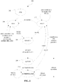
- FIG. 2 is a state diagram 200 of a CSC that is in communication with a CSC reader implementing one embodiment of a process for CSC detection and selection.
- the CSC is a type-A CSC.
- POR power on reset
- the CSC will start in the POR (power on reset) state 202 and then go to the IDLE state 204.
- a CSC will also go to the IDLE state 204 if it receives any unexpected commands while it is in the READY 1 state 206, ACTIVE state 208, or AUTHENTICATED state 210.
- the CSC will go to the READY 1 state 206.
- REQA request type A
- WUPA wakeup type A
- the REQA command allows the CSC reader to go through a number of CSCs, since the CSCs will not respond to the REQA command after they are in the HALT state 212. If the REQA command is continually issued, a CSC will respond every other time (i.e., toggle between IDLE state 204 and "error state").
- the CSC If the CSC receives a SELECT command while it is in the READY 1 state 206, the CSC will go to the ACTIVE state 208. Then, an AUTHENTICATE command can be issued to place the CSC in the AUTHENTICATED state 210. Once in the AUTHENTICATED state 210, READ and WRITE operations can be performed on the CSC so that a transaction can be conducted. If a HALT command is received by the CSC while it is in either the ACTIVE state 208 or the AUTHENTICATED state 210, the CSC will go to the HALT state 212.
- an RF-RESET command will place the CSC into the IDLE state 204 and a WUPA command will place the CSC into the READY 1 state 206. All other commands will be ignored and the CSC will remain in the HALT state 212.
- FIG. 3 is an illustration of a typical RF field amplitude over time during communication between a CSC reader and a CSC.
- the CSC reader transmits a signal in the outbound data and the CSC responds by load-modulating the RF field amplitude using Manchester coding of a sub-carrier.
- the transmitted signal can be a polling signal, or a signal to issue a command such as an ANTICOLLISION or SELECT command, and the CSC response can vary depending on the type of transmitted signal. In this example, there is only one CSC, so the response does not contain a collision.
- FIG. 4 is an illustration of a typical RF field amplitude over time during communication between a contactless smart card reader and multiple CSCs.
- two CSCs receive enough power.
- the CSCs respond to a signal transmitted by the CSC reader by load modulating the RF field amplitude. The difference in response causes a collision in the Manchester coded data.
- the CSC reader can detect the collision if the load modulation from the CSCs is of similar strength.
- FIG. 5 is an illustration of an RF field amplitude over time during communication between one embodiment of a CSC reader and multiple CSCs.
- one of two cards has sufficient power to operate at the lower power level and is selected and put into the HALT state.
- the CSC reader increases the power level and the second card now responds to the poll.
- the corresponding polling pattern would be: 1) poll for cards at 80% RF strength, 2) find card(s) and send to halt state, 3) increase RF strength to 100% and poll again, 4) find card(s) and send to halt state, and 5) choose correct card from list.
- the CSC reader can start at any RF power level between 0 and 100%, and the power level can be increased or decreased any number of times in any increments. For example, the CSC reader can start at 50% RF power and increase the RF power in 10% increments, polling for cards after each increase until 100% power is reached.
- FIG. 6 is a block diagram of one embodiment of a CSC reader 600.
- CSC reader 600 includes a computer processor 602, an RF transceiver 604, and a memory module 606.
- Memory module 606 can be any non-transitory machine-readable media, such as optical disks or flash memory devices.
- Software 608 is stored in memory module 606 and provides instructions to computer processor 602 according to any of the embodiments described herein.
- Computer processor 602 utilizes RF transceiver 604 to generate an RF field and communicates with CSCs within the RF field by transmitting and receiving RF signals through the RF field. It will be understood that the CSC reader 600 can include additional components not shown in FIG.
- a communication interface for communicating with a network (which may be separate or combined with the RF transceiver 604). Additionally or alternatively, alternative embodiments may combine, separate, omit, and/or rearrange the components shown in FIG. 6 .
- CSCs are not limited to transit, but can also be used anywhere CSCs are used, such as retail, banking, etc.
- type-A CSCs as defined by the ISO14443 standard, are used as examples in this description, the embodiments described herein also apply to other types of CSCs, including but not limited to type-B, proposed type-C, and proposed type-D, as well as a combination of different types of CSCs.
- CSCs do not follow the standard exactly, which is another reason why sorting through multiple CSCs using varying power levels would be more reliable.
- embodiments of the methods may be implemented by hardware, software, firmware, middleware, microcode, hardware description languages, or any combination thereof.
- the program code or code segments to perform the associated tasks may be stored in a computer-readable medium such as a storage medium. Processors may perform the associated tasks.
Landscapes
- Engineering & Computer Science (AREA)
- Health & Medical Sciences (AREA)
- Toxicology (AREA)
- Physics & Mathematics (AREA)
- Electromagnetism (AREA)
- General Health & Medical Sciences (AREA)
- Artificial Intelligence (AREA)
- Computer Vision & Pattern Recognition (AREA)
- General Physics & Mathematics (AREA)
- Theoretical Computer Science (AREA)
- Computer Networks & Wireless Communication (AREA)
- Mobile Radio Communication Systems (AREA)
Claims (11)
- Procédé (100) exécuté par un lecteur de carte à puce sans contact "CSC" destiné à la détection et sélection de CSC, le procédé comprenant
la génération (102) d'un champ de radiofréquence "RF" qui définit une plage de communication pour le lecteur de CSC ;
l'émission (104) d'un premier signal d'invitation à émettre dans le champ RF ;
la détection (106) d'une modulation dans le champ RF indiquant qu'une première CSC est présente dans le champ RF et a répondu au premier signal d'invitation à émettre ;
l'inspection (108) de la modulation afin de détecter une collision potentielle, la collision se produisant si plus d'une CSC présente dans le champ RF répond au premier signal d'invitation à émettre ;
la détermination du fait que la modulation ne contient pas la collision ;
l'émission (112) d'une commande d'arrêt à la première CSC en réponse à la détermination du fait que la modulation ne contient pas la collision, la commande d'arrêt donnant consigne à la première CSC de ne répondre qu'à au moins une commande spécifique ;
caractérisé par les étapes supplémentaires consistant en :l'augmentation ou la diminution (114) d'un niveau de puissance du champ RF après l'émission (112) de la commande d'arrêt ; etl'émission (116) d'un second signal d'invitation à émettre dans le champ RF après l'émission de la commande d'arrêt à l'intention de la première CSC et après l'augmentation ou la diminution du niveau de puissance du champ RF. - Procédé selon la revendication 1, dans lequel :
le second signal d'invitation à émettre est émis (116) dans le champ RF après qu'une période de temps prédéterminée s'est écoulée depuis l'émission de la commande d'arrêt à l'intention de la première CSC. - Procédé selon la revendication 1, dans lequel le second signal d'invitation à émettre est émis (116) dans le champ RF pendant une période de temps prédéterminée, et le procédé comprend en outre :l'émission d'une commande de réveil à l'intention de la première CSC après que la période de temps prédéterminée s'est écoulée ; etla sélection de la première CSC afin d'effectuer (120) une transaction.
- Procédé selon la revendication 1, comprenant en outre :la détection (118) de la présence d'une seconde CSC dans le champ RF ; etla génération d'une notification visuelle et/ou d'une notification audio pour un utilisateur, la notification informant l'utilisateur que plus d'une CSC a été présentée.
- Procédé selon la revendication 1, comprenant en outre :la détection (118) de la présence d'une seconde CSC dans le champ RF ; etla sélection de l'une des première CSC et seconde CSC afin d'effectuer (120) une transaction en fonction d'un critère prédéfini.
- Lecteur de carte à puce sans contact "CSC" (600) destiné à la détection et sélection de CSC, le lecteur de CSC comprenant :un émetteur-récepteur de radiofréquence "RF" (604) configuré pour générer un champ RF, et pour émettre et recevoir des signaux dans le champ RF ; etun processeur informatique (602) couplé à l'émetteur-récepteur RF (604) et configuré pour utiliser l'émetteur-récepteur RF (604) afin d'émettre un premier signal d'invitation à émettre dans le champ RF, de détecter une modulation dans le champ RF indiquant qu'une première CSC est présente dans le champ RF et a répondu au premier signal d'invitation à émettre, d'inspecter la modulation afin de détecter une collision potentielle, de déterminer que la modulation ne contient pas la collision, d'utiliser l'émetteur-récepteur RF pour émettre une commande d'arrêt à l'intention de la première CSC en réponse à la détermination du fait que la modulation ne contient pas la collision, d'augmenter ou de diminuer un niveau de puissance du champ RF après l'émission de la commande d'arrêt, et d'émettre un second signal d'invitation à émettre dans le champ RF après l'émission de la commande d'arrêt à l'intention de la première CSC et l'augmentation ou la diminution du niveau de puissance du champ RF,la collision se produisant si plus d'une CSC présente dans le champ RF répond au premier signal d'invitation à émettre, et la commande d'arrêt donnant consigne à la première CSC de ne répondre qu'à au moins une commande spécifique.
- Lecteur de CSC (600) selon la revendication 6, dans lequel le processeur informatique (602) est en outre configuré pour utiliser l'émetteur-récepteur RF (604) afin d'émettre le second signal d'invitation à émettre dans le champ RF après qu'une période de temps prédéterminée s'est écoulée depuis l'émission de la commande d'arrêt à l'intention de la première CSC.
- Lecteur de CSC (600) selon la revendication 6, dans lequel le processeur d'ordinateur (602) est en outre configuré pour utiliser l'émetteur-récepteur RF (604) afin d'émettre le second signal d'invitation à émettre dans le champ RF pendant une période de temps prédéterminée ; pour utiliser l'émetteur-récepteur RF afin d'émettre une commande de réveil à l'intention de la première CSC après l'écoulement de la période de temps prédéterminée, et sélectionner la première CSC afin d'effectuer une transaction.
- Lecteur de CSC (600) selon la revendication 6, dans lequel le processeur informatique (602) est en outre configuré pour détecter la présence d'une seconde CSC dans le champ RF, et pour générer au moins une notification visuelle et/ou une notification audio pour un utilisateur, la notification informant l'utilisateur que plus d'une CSC a été présentée.
- Lecteur de CSC (600) selon la revendication 6, dans lequel le processeur informatique (602) est en outre configuré pour détecter la présence d'une seconde CSC dans le champ RF, et pour sélectionner l'une des première CSC et seconde CSC afin d'effectuer une transaction en fonction d'un critère prédéfini.
- Support non transitoire lisible par ordinateur (606), contenant des instructions (608) qui, lorsqu'elles sont exécutées, amènent un ordinateur à effectuer un ensemble d'opérations comprenant les étapes du procédé selon l'une quelconque des revendications 1 à 5.
Applications Claiming Priority (4)
| Application Number | Priority Date | Filing Date | Title |
|---|---|---|---|
| US201361867931P | 2013-08-20 | 2013-08-20 | |
| US201461982638P | 2014-04-22 | 2014-04-22 | |
| US14/463,383 US9323964B2 (en) | 2013-08-20 | 2014-08-19 | Card detection and selection |
| PCT/US2014/051898 WO2015026946A1 (fr) | 2013-08-20 | 2014-08-20 | Détection et sélection de carte à puce intelligente sans fil |
Publications (2)
| Publication Number | Publication Date |
|---|---|
| EP3036683A1 EP3036683A1 (fr) | 2016-06-29 |
| EP3036683B1 true EP3036683B1 (fr) | 2020-04-15 |
Family
ID=52479834
Family Applications (1)
| Application Number | Title | Priority Date | Filing Date |
|---|---|---|---|
| EP14758759.6A Active EP3036683B1 (fr) | 2013-08-20 | 2014-08-20 | Détection et sélection de carte à puce intelligente sans fil |
Country Status (5)
| Country | Link |
|---|---|
| US (1) | US9323964B2 (fr) |
| EP (1) | EP3036683B1 (fr) |
| AU (1) | AU2014308866B2 (fr) |
| CA (1) | CA2919721A1 (fr) |
| WO (1) | WO2015026946A1 (fr) |
Families Citing this family (2)
| Publication number | Priority date | Publication date | Assignee | Title |
|---|---|---|---|---|
| US9048819B2 (en) * | 2006-11-18 | 2015-06-02 | RF Micron, Inc. | Method and apparatus for detecting RF field strength |
| CN109118627A (zh) * | 2018-08-15 | 2019-01-01 | 深圳市凯迪仕智能科技有限公司 | 一种自动锁控制电路及控制方法 |
Citations (1)
| Publication number | Priority date | Publication date | Assignee | Title |
|---|---|---|---|---|
| WO2006083493A2 (fr) * | 2005-02-04 | 2006-08-10 | Atmel Corporation | Procede de detection de carte rf dans un systeme exempt de contact |
Family Cites Families (17)
| Publication number | Priority date | Publication date | Assignee | Title |
|---|---|---|---|---|
| ES2207833T3 (es) | 1997-05-14 | 2004-06-01 | Btg International Limited | Sistema de identificacion mejorado. |
| EP0924635A3 (fr) | 1997-12-15 | 2001-01-10 | Data Investments Limited | Système électronique d'identification avec un lecteur et une pluralité de transpondeurs |
| JP3239294B2 (ja) * | 1998-01-12 | 2001-12-17 | 株式会社デンソー | 非接触式icカード通信システム及びicカード通信方法 |
| US6480143B1 (en) | 1998-11-09 | 2002-11-12 | Supersensor (Proprietary) Limited | Electronic identification system |
| US6535109B1 (en) | 1998-12-01 | 2003-03-18 | Texas Instruments Sensors And Controls, Inc. | System and method for communicating with multiple transponders |
| JP4284745B2 (ja) | 1999-04-13 | 2009-06-24 | 株式会社デンソー | Icカード通信システム |
| US7011250B2 (en) | 2001-12-20 | 2006-03-14 | Matsushita Electric Industrial Co., Ltd. | IC card reader/writer, identification method and program |
| US6707376B1 (en) * | 2002-08-09 | 2004-03-16 | Sensormatic Electronics Corporation | Pulsed power method for increased read range for a radio frequency identification reader |
| US7880587B2 (en) * | 2003-10-15 | 2011-02-01 | Nxp B.V. | Communication system and anti-collision method |
| AU2005274949A1 (en) * | 2004-07-15 | 2006-02-23 | Mastercard International Incorporated | Payment card signal characterization methods and circuits |
| US20060176152A1 (en) | 2005-02-10 | 2006-08-10 | Psc Scanning, Inc. | RFID power ramping for tag singulation |
| US20060273176A1 (en) * | 2005-06-03 | 2006-12-07 | Actividentity, Inc. | Blocking contactless personal security device |
| WO2006138440A2 (fr) * | 2005-06-16 | 2006-12-28 | Visa International Service Association | Systemes et procedes d'actionnement sans contact |
| US20080042803A1 (en) | 2006-07-27 | 2008-02-21 | Joshua Posamentier | Adjusting signal strength used to detect tags |
| US8519823B2 (en) * | 2006-10-31 | 2013-08-27 | Symbol Technologies, Inc. | Radio frequency identification (RFID) tag location systems and methods |
| US8446256B2 (en) * | 2008-05-19 | 2013-05-21 | Sirit Technologies Inc. | Multiplexing radio frequency signals |
| US8994501B2 (en) * | 2011-12-19 | 2015-03-31 | Symbol Technologies, Inc. | Method and apparatus for reading radio frequency identification tags with lowest power consumption |
-
2014
- 2014-08-19 US US14/463,383 patent/US9323964B2/en active Active
- 2014-08-20 AU AU2014308866A patent/AU2014308866B2/en not_active Ceased
- 2014-08-20 EP EP14758759.6A patent/EP3036683B1/fr active Active
- 2014-08-20 WO PCT/US2014/051898 patent/WO2015026946A1/fr not_active Ceased
- 2014-08-20 CA CA2919721A patent/CA2919721A1/fr not_active Abandoned
Patent Citations (1)
| Publication number | Priority date | Publication date | Assignee | Title |
|---|---|---|---|---|
| WO2006083493A2 (fr) * | 2005-02-04 | 2006-08-10 | Atmel Corporation | Procede de detection de carte rf dans un systeme exempt de contact |
Also Published As
| Publication number | Publication date |
|---|---|
| US9323964B2 (en) | 2016-04-26 |
| AU2014308866B2 (en) | 2018-08-02 |
| US20150054624A1 (en) | 2015-02-26 |
| EP3036683A1 (fr) | 2016-06-29 |
| CA2919721A1 (fr) | 2015-02-26 |
| WO2015026946A1 (fr) | 2015-02-26 |
| AU2014308866A1 (en) | 2016-02-11 |
Similar Documents
| Publication | Publication Date | Title |
|---|---|---|
| EP2837104B1 (fr) | Détection d'un branchement de communication par le biais d'une surveillance de signaux | |
| CN101645129B (zh) | 一种在近场通信中提供安全的方法和装置 | |
| US10650201B1 (en) | RFID tags with port-dependent functionality | |
| EP3387581B1 (fr) | Systèmes et procédés pour un transpondeur connecté en infonuagique | |
| US20130084798A1 (en) | Single nfc device identity selection on a multiple-identity supported device | |
| EP2602942B1 (fr) | Détection de présence de dispositifs de communication en champ proche (nfc) | |
| EP4693916A1 (fr) | Procédé et appareil de commande de communication en champ proche, et dispositif de communication en champ proche | |
| EP3036683B1 (fr) | Détection et sélection de carte à puce intelligente sans fil | |
| EP2770755A1 (fr) | Identification par balise de communication de champ proche | |
| CN101645130B (zh) | 一种在近场通信中提供安全的方法和装置 | |
| US9154959B2 (en) | Systems and methods for securing near field communications | |
| CN108039925B (zh) | 信号处理方法、装置、设备及存储介质 | |
| JP5056577B2 (ja) | リーダライタ及び非接触icモジュール | |
| US12001908B2 (en) | Method for identifying a passive RFID card | |
| US9838831B2 (en) | Mobile proximity coupling device with display | |
| KR102061013B1 (ko) | 근거리 무선 통신을 이용한 단말에서의 데이터 송수신 방법 및 장치와 그 방법에 대한 프로그램 소스를 저장한 기록 매체 | |
| JP4845852B2 (ja) | リーダライタ | |
| CN115423065B (zh) | 用于检测卡片的方法、装置、电子设备及存储介质 | |
| US9838087B2 (en) | Mobile proximity coupling device | |
| KR101268809B1 (ko) | 태그 인식 방법 및 태그 인식 장치 | |
| KR20130016048A (ko) | Nfc 단말기를 이용한 안전 결제 제공방법, nfc 단말기, 및 rf 결제장치 |
Legal Events
| Date | Code | Title | Description |
|---|---|---|---|
| PUAI | Public reference made under article 153(3) epc to a published international application that has entered the european phase |
Free format text: ORIGINAL CODE: 0009012 |
|
| 17P | Request for examination filed |
Effective date: 20160304 |
|
| AK | Designated contracting states |
Kind code of ref document: A1 Designated state(s): AL AT BE BG CH CY CZ DE DK EE ES FI FR GB GR HR HU IE IS IT LI LT LU LV MC MK MT NL NO PL PT RO RS SE SI SK SM TR |
|
| AX | Request for extension of the european patent |
Extension state: BA ME |
|
| DAX | Request for extension of the european patent (deleted) | ||
| STAA | Information on the status of an ep patent application or granted ep patent |
Free format text: STATUS: EXAMINATION IS IN PROGRESS |
|
| 17Q | First examination report despatched |
Effective date: 20180206 |
|
| GRAP | Despatch of communication of intention to grant a patent |
Free format text: ORIGINAL CODE: EPIDOSNIGR1 |
|
| STAA | Information on the status of an ep patent application or granted ep patent |
Free format text: STATUS: GRANT OF PATENT IS INTENDED |
|
| INTG | Intention to grant announced |
Effective date: 20191113 |
|
| GRAS | Grant fee paid |
Free format text: ORIGINAL CODE: EPIDOSNIGR3 |
|
| GRAA | (expected) grant |
Free format text: ORIGINAL CODE: 0009210 |
|
| STAA | Information on the status of an ep patent application or granted ep patent |
Free format text: STATUS: THE PATENT HAS BEEN GRANTED |
|
| AK | Designated contracting states |
Kind code of ref document: B1 Designated state(s): AL AT BE BG CH CY CZ DE DK EE ES FI FR GB GR HR HU IE IS IT LI LT LU LV MC MK MT NL NO PL PT RO RS SE SI SK SM TR |
|
| REG | Reference to a national code |
Ref country code: CH Ref legal event code: EP |
|
| REG | Reference to a national code |
Ref country code: DE Ref legal event code: R096 Ref document number: 602014063809 Country of ref document: DE |
|
| REG | Reference to a national code |
Ref country code: IE Ref legal event code: FG4D |
|
| REG | Reference to a national code |
Ref country code: AT Ref legal event code: REF Ref document number: 1258145 Country of ref document: AT Kind code of ref document: T Effective date: 20200515 |
|
| REG | Reference to a national code |
Ref country code: NL Ref legal event code: MP Effective date: 20200415 |
|
| REG | Reference to a national code |
Ref country code: LT Ref legal event code: MG4D |
|
| PG25 | Lapsed in a contracting state [announced via postgrant information from national office to epo] |
Ref country code: IS Free format text: LAPSE BECAUSE OF FAILURE TO SUBMIT A TRANSLATION OF THE DESCRIPTION OR TO PAY THE FEE WITHIN THE PRESCRIBED TIME-LIMIT Effective date: 20200815 Ref country code: SE Free format text: LAPSE BECAUSE OF FAILURE TO SUBMIT A TRANSLATION OF THE DESCRIPTION OR TO PAY THE FEE WITHIN THE PRESCRIBED TIME-LIMIT Effective date: 20200415 Ref country code: NO Free format text: LAPSE BECAUSE OF FAILURE TO SUBMIT A TRANSLATION OF THE DESCRIPTION OR TO PAY THE FEE WITHIN THE PRESCRIBED TIME-LIMIT Effective date: 20200715 Ref country code: GR Free format text: LAPSE BECAUSE OF FAILURE TO SUBMIT A TRANSLATION OF THE DESCRIPTION OR TO PAY THE FEE WITHIN THE PRESCRIBED TIME-LIMIT Effective date: 20200716 Ref country code: FI Free format text: LAPSE BECAUSE OF FAILURE TO SUBMIT A TRANSLATION OF THE DESCRIPTION OR TO PAY THE FEE WITHIN THE PRESCRIBED TIME-LIMIT Effective date: 20200415 Ref country code: LT Free format text: LAPSE BECAUSE OF FAILURE TO SUBMIT A TRANSLATION OF THE DESCRIPTION OR TO PAY THE FEE WITHIN THE PRESCRIBED TIME-LIMIT Effective date: 20200415 Ref country code: NL Free format text: LAPSE BECAUSE OF FAILURE TO SUBMIT A TRANSLATION OF THE DESCRIPTION OR TO PAY THE FEE WITHIN THE PRESCRIBED TIME-LIMIT Effective date: 20200415 Ref country code: PT Free format text: LAPSE BECAUSE OF FAILURE TO SUBMIT A TRANSLATION OF THE DESCRIPTION OR TO PAY THE FEE WITHIN THE PRESCRIBED TIME-LIMIT Effective date: 20200817 |
|
| REG | Reference to a national code |
Ref country code: AT Ref legal event code: MK05 Ref document number: 1258145 Country of ref document: AT Kind code of ref document: T Effective date: 20200415 |
|
| PG25 | Lapsed in a contracting state [announced via postgrant information from national office to epo] |
Ref country code: LV Free format text: LAPSE BECAUSE OF FAILURE TO SUBMIT A TRANSLATION OF THE DESCRIPTION OR TO PAY THE FEE WITHIN THE PRESCRIBED TIME-LIMIT Effective date: 20200415 Ref country code: HR Free format text: LAPSE BECAUSE OF FAILURE TO SUBMIT A TRANSLATION OF THE DESCRIPTION OR TO PAY THE FEE WITHIN THE PRESCRIBED TIME-LIMIT Effective date: 20200415 Ref country code: RS Free format text: LAPSE BECAUSE OF FAILURE TO SUBMIT A TRANSLATION OF THE DESCRIPTION OR TO PAY THE FEE WITHIN THE PRESCRIBED TIME-LIMIT Effective date: 20200415 Ref country code: BG Free format text: LAPSE BECAUSE OF FAILURE TO SUBMIT A TRANSLATION OF THE DESCRIPTION OR TO PAY THE FEE WITHIN THE PRESCRIBED TIME-LIMIT Effective date: 20200715 |
|
| PG25 | Lapsed in a contracting state [announced via postgrant information from national office to epo] |
Ref country code: AL Free format text: LAPSE BECAUSE OF FAILURE TO SUBMIT A TRANSLATION OF THE DESCRIPTION OR TO PAY THE FEE WITHIN THE PRESCRIBED TIME-LIMIT Effective date: 20200415 |
|
| REG | Reference to a national code |
Ref country code: DE Ref legal event code: R097 Ref document number: 602014063809 Country of ref document: DE |
|
| PG25 | Lapsed in a contracting state [announced via postgrant information from national office to epo] |
Ref country code: EE Free format text: LAPSE BECAUSE OF FAILURE TO SUBMIT A TRANSLATION OF THE DESCRIPTION OR TO PAY THE FEE WITHIN THE PRESCRIBED TIME-LIMIT Effective date: 20200415 Ref country code: IT Free format text: LAPSE BECAUSE OF FAILURE TO SUBMIT A TRANSLATION OF THE DESCRIPTION OR TO PAY THE FEE WITHIN THE PRESCRIBED TIME-LIMIT Effective date: 20200415 Ref country code: SM Free format text: LAPSE BECAUSE OF FAILURE TO SUBMIT A TRANSLATION OF THE DESCRIPTION OR TO PAY THE FEE WITHIN THE PRESCRIBED TIME-LIMIT Effective date: 20200415 Ref country code: DK Free format text: LAPSE BECAUSE OF FAILURE TO SUBMIT A TRANSLATION OF THE DESCRIPTION OR TO PAY THE FEE WITHIN THE PRESCRIBED TIME-LIMIT Effective date: 20200415 Ref country code: ES Free format text: LAPSE BECAUSE OF FAILURE TO SUBMIT A TRANSLATION OF THE DESCRIPTION OR TO PAY THE FEE WITHIN THE PRESCRIBED TIME-LIMIT Effective date: 20200415 Ref country code: CZ Free format text: LAPSE BECAUSE OF FAILURE TO SUBMIT A TRANSLATION OF THE DESCRIPTION OR TO PAY THE FEE WITHIN THE PRESCRIBED TIME-LIMIT Effective date: 20200415 Ref country code: AT Free format text: LAPSE BECAUSE OF FAILURE TO SUBMIT A TRANSLATION OF THE DESCRIPTION OR TO PAY THE FEE WITHIN THE PRESCRIBED TIME-LIMIT Effective date: 20200415 Ref country code: RO Free format text: LAPSE BECAUSE OF FAILURE TO SUBMIT A TRANSLATION OF THE DESCRIPTION OR TO PAY THE FEE WITHIN THE PRESCRIBED TIME-LIMIT Effective date: 20200415 |
|
| PLBE | No opposition filed within time limit |
Free format text: ORIGINAL CODE: 0009261 |
|
| STAA | Information on the status of an ep patent application or granted ep patent |
Free format text: STATUS: NO OPPOSITION FILED WITHIN TIME LIMIT |
|
| PG25 | Lapsed in a contracting state [announced via postgrant information from national office to epo] |
Ref country code: PL Free format text: LAPSE BECAUSE OF FAILURE TO SUBMIT A TRANSLATION OF THE DESCRIPTION OR TO PAY THE FEE WITHIN THE PRESCRIBED TIME-LIMIT Effective date: 20200415 Ref country code: SK Free format text: LAPSE BECAUSE OF FAILURE TO SUBMIT A TRANSLATION OF THE DESCRIPTION OR TO PAY THE FEE WITHIN THE PRESCRIBED TIME-LIMIT Effective date: 20200415 |
|
| REG | Reference to a national code |
Ref country code: DE Ref legal event code: R119 Ref document number: 602014063809 Country of ref document: DE |
|
| 26N | No opposition filed |
Effective date: 20210118 |
|
| PG25 | Lapsed in a contracting state [announced via postgrant information from national office to epo] |
Ref country code: MC Free format text: LAPSE BECAUSE OF FAILURE TO SUBMIT A TRANSLATION OF THE DESCRIPTION OR TO PAY THE FEE WITHIN THE PRESCRIBED TIME-LIMIT Effective date: 20200415 |
|
| REG | Reference to a national code |
Ref country code: CH Ref legal event code: PL |
|
| GBPC | Gb: european patent ceased through non-payment of renewal fee |
Effective date: 20200820 |
|
| PG25 | Lapsed in a contracting state [announced via postgrant information from national office to epo] |
Ref country code: CH Free format text: LAPSE BECAUSE OF NON-PAYMENT OF DUE FEES Effective date: 20200831 Ref country code: LI Free format text: LAPSE BECAUSE OF NON-PAYMENT OF DUE FEES Effective date: 20200831 Ref country code: LU Free format text: LAPSE BECAUSE OF NON-PAYMENT OF DUE FEES Effective date: 20200820 |
|
| REG | Reference to a national code |
Ref country code: BE Ref legal event code: MM Effective date: 20200831 |
|
| PG25 | Lapsed in a contracting state [announced via postgrant information from national office to epo] |
Ref country code: SI Free format text: LAPSE BECAUSE OF FAILURE TO SUBMIT A TRANSLATION OF THE DESCRIPTION OR TO PAY THE FEE WITHIN THE PRESCRIBED TIME-LIMIT Effective date: 20200415 |
|
| PG25 | Lapsed in a contracting state [announced via postgrant information from national office to epo] |
Ref country code: DE Free format text: LAPSE BECAUSE OF NON-PAYMENT OF DUE FEES Effective date: 20210302 Ref country code: FR Free format text: LAPSE BECAUSE OF NON-PAYMENT OF DUE FEES Effective date: 20200831 |
|
| PG25 | Lapsed in a contracting state [announced via postgrant information from national office to epo] |
Ref country code: BE Free format text: LAPSE BECAUSE OF NON-PAYMENT OF DUE FEES Effective date: 20200831 Ref country code: IE Free format text: LAPSE BECAUSE OF NON-PAYMENT OF DUE FEES Effective date: 20200820 Ref country code: GB Free format text: LAPSE BECAUSE OF NON-PAYMENT OF DUE FEES Effective date: 20200820 |
|
| PG25 | Lapsed in a contracting state [announced via postgrant information from national office to epo] |
Ref country code: TR Free format text: LAPSE BECAUSE OF FAILURE TO SUBMIT A TRANSLATION OF THE DESCRIPTION OR TO PAY THE FEE WITHIN THE PRESCRIBED TIME-LIMIT Effective date: 20200415 Ref country code: MT Free format text: LAPSE BECAUSE OF FAILURE TO SUBMIT A TRANSLATION OF THE DESCRIPTION OR TO PAY THE FEE WITHIN THE PRESCRIBED TIME-LIMIT Effective date: 20200415 Ref country code: CY Free format text: LAPSE BECAUSE OF FAILURE TO SUBMIT A TRANSLATION OF THE DESCRIPTION OR TO PAY THE FEE WITHIN THE PRESCRIBED TIME-LIMIT Effective date: 20200415 |
|
| PG25 | Lapsed in a contracting state [announced via postgrant information from national office to epo] |
Ref country code: MK Free format text: LAPSE BECAUSE OF FAILURE TO SUBMIT A TRANSLATION OF THE DESCRIPTION OR TO PAY THE FEE WITHIN THE PRESCRIBED TIME-LIMIT Effective date: 20200415 |