EP3036714B1 - Erkennung von unstrukturiertem strassenrand - Google Patents
Erkennung von unstrukturiertem strassenrand Download PDFInfo
- Publication number
- EP3036714B1 EP3036714B1 EP13891976.6A EP13891976A EP3036714B1 EP 3036714 B1 EP3036714 B1 EP 3036714B1 EP 13891976 A EP13891976 A EP 13891976A EP 3036714 B1 EP3036714 B1 EP 3036714B1
- Authority
- EP
- European Patent Office
- Prior art keywords
- pixel
- road
- color
- vectors
- pixels
- Prior art date
- Legal status (The legal status is an assumption and is not a legal conclusion. Google has not performed a legal analysis and makes no representation as to the accuracy of the status listed.)
- Active
Links
Images


Classifications
-
- G—PHYSICS
- G06—COMPUTING OR CALCULATING; COUNTING
- G06T—IMAGE DATA PROCESSING OR GENERATION, IN GENERAL
- G06T7/00—Image analysis
- G06T7/10—Segmentation; Edge detection
- G06T7/11—Region-based segmentation
-
- G—PHYSICS
- G06—COMPUTING OR CALCULATING; COUNTING
- G06T—IMAGE DATA PROCESSING OR GENERATION, IN GENERAL
- G06T7/00—Image analysis
- G06T7/10—Segmentation; Edge detection
- G06T7/12—Edge-based segmentation
-
- G—PHYSICS
- G06—COMPUTING OR CALCULATING; COUNTING
- G06T—IMAGE DATA PROCESSING OR GENERATION, IN GENERAL
- G06T7/00—Image analysis
- G06T7/10—Segmentation; Edge detection
- G06T7/136—Segmentation; Edge detection involving thresholding
-
- G—PHYSICS
- G06—COMPUTING OR CALCULATING; COUNTING
- G06T—IMAGE DATA PROCESSING OR GENERATION, IN GENERAL
- G06T7/00—Image analysis
- G06T7/10—Segmentation; Edge detection
- G06T7/143—Segmentation; Edge detection involving probabilistic approaches, e.g. Markov random field [MRF] modelling
-
- G—PHYSICS
- G06—COMPUTING OR CALCULATING; COUNTING
- G06T—IMAGE DATA PROCESSING OR GENERATION, IN GENERAL
- G06T7/00—Image analysis
- G06T7/10—Segmentation; Edge detection
- G06T7/181—Segmentation; Edge detection involving edge growing; involving edge linking
-
- G—PHYSICS
- G06—COMPUTING OR CALCULATING; COUNTING
- G06V—IMAGE OR VIDEO RECOGNITION OR UNDERSTANDING
- G06V10/00—Arrangements for image or video recognition or understanding
- G06V10/20—Image preprocessing
- G06V10/26—Segmentation of patterns in the image field; Cutting or merging of image elements to establish the pattern region, e.g. clustering-based techniques; Detection of occlusion
- G06V10/267—Segmentation of patterns in the image field; Cutting or merging of image elements to establish the pattern region, e.g. clustering-based techniques; Detection of occlusion by performing operations on regions, e.g. growing, shrinking or watersheds
-
- G—PHYSICS
- G06—COMPUTING OR CALCULATING; COUNTING
- G06V—IMAGE OR VIDEO RECOGNITION OR UNDERSTANDING
- G06V10/00—Arrangements for image or video recognition or understanding
- G06V10/40—Extraction of image or video features
- G06V10/56—Extraction of image or video features relating to colour
-
- G—PHYSICS
- G06—COMPUTING OR CALCULATING; COUNTING
- G06V—IMAGE OR VIDEO RECOGNITION OR UNDERSTANDING
- G06V20/00—Scenes; Scene-specific elements
- G06V20/50—Context or environment of the image
- G06V20/56—Context or environment of the image exterior to a vehicle by using sensors mounted on the vehicle
- G06V20/588—Recognition of the road, e.g. of lane markings; Recognition of the vehicle driving pattern in relation to the road
-
- G—PHYSICS
- G06—COMPUTING OR CALCULATING; COUNTING
- G06T—IMAGE DATA PROCESSING OR GENERATION, IN GENERAL
- G06T2207/00—Indexing scheme for image analysis or image enhancement
- G06T2207/10—Image acquisition modality
- G06T2207/10024—Color image
-
- G—PHYSICS
- G06—COMPUTING OR CALCULATING; COUNTING
- G06T—IMAGE DATA PROCESSING OR GENERATION, IN GENERAL
- G06T2207/00—Indexing scheme for image analysis or image enhancement
- G06T2207/30—Subject of image; Context of image processing
- G06T2207/30248—Vehicle exterior or interior
- G06T2207/30252—Vehicle exterior; Vicinity of vehicle
- G06T2207/30256—Lane; Road marking
Definitions
- the present disclosure generally relates to unstructured road boundary detection.
- MIGUEL ANGEL SOTELO ET AL disclose in "A Color Vision-Based Lane Tracking System for Autonomous Driving on Unmarked Roads" in AUTONOMOUS ROBOTS, vol. 16, no. 1, 1 January 2004 (2004-01-01), pages 95-116 , a system which is intended to perform autonomous driving on an unmarked road in which the road boundaries are detected based on image postprocessing.
- the embodiment of the invention relates to a method for detecting an unstructured road boundary as claimed in claim 1 and corresponding system as claimed in claim 8.
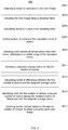
- FIG. 1 illustrates a schematic flow chart of an unstructured road boundary detection method S10 according to one embodiment.
- the color image may be captured by a camera mounted on a vehicle.
- preprocessing the color image to suppress noise pixels' effect In S102, preprocessing the color image to suppress noise pixels' effect.
- the captured image tends to be affected by noise, such as speckle noise, and/or salt-and-pepper noise, which may adversely influence subsequent image feature identification.
- Filtering typically a vector median filtering algorithm, may be used to remove those noise pixels from the color image.
- an image processing method S20 may be used to suppress noise pixels' effect, which is illustrated in FIG. 2 .
- a vector may correspond to a pixel, where the vector represents a line pointing from an original point to a point corresponding to the pixel in a color space.
- the captured color image may be constructed in a red-green-blue (RGB) color space.
- RGB red-green-blue
- a vector of a corresponding pixel may be obtained in the RGB color space, which may include components representing color information of its corresponding pixel, such as red, green and blue.
- the original point may have its components all equal to zero.
- sampling the color image using a sampling frame may be sampled interlacedly, for example, only even rows and even columns are sampled.
- a "sampling frame" also known as a sliding window
- the sampling frame may move across the color image in both vertical and horizontal directions, such as from the top-left corner of the color image to the bottom-right corner of the color image.
- Such a sampling frame may have a predetermined size (m ⁇ n), for example a size of 3 ⁇ 3, 7 ⁇ 7 or 11 ⁇ 11, where m and n may be an odd number greater than 1.
- a set of N vectors may be sampled in the sampling frame.
- a conventional vector median filtering algorithm may be used to preprocess vectors of the color image to suppress noises.
- the conventional vector median filtering algorithm may take a large amount of computation.
- an improved image processing method is provided, which may greatly reduce complexity of computations.
- S207 sorting vectors according to the calculated norms of vectors.
- the sampled vectors may be sorted in an ascending or descending order.
- a first number t1 of vectors may be obtained by filtering out a number of vectors having the maximum norms and a number of vectors having the minimum norms, so as to form a new set of t1 vectors.
- the value of t1 is important for filtering noise and reducing computation complexity, which may be adjusted according to the characteristics of the noise and computation requirements. For a sampling frame having a size of 3 ⁇ 3, the value of t1 may be set in a range of 5 to 7.
- obtaining a weighted average vector for the first number of vectors may be obtained by calculating weighted average of m th components of the first number of vectors.
- the value of w j may be a reciprocal of a distance between a pixel corresponding to the j th vector and the central position of the sampling frame. Generally, the closer to the central position of the sampling frame, the greater the value of w j . When a sampling frame having a smaller size is selected, the value of w j may be set to 1.
- a second number t2 of vectors having the minimum norms of differences with the weighted average vector may be identified from the set of t1 vectors, so as to form a new set of t2 vectors.
- the value of t2 is also important for filtering noise and reduction of computations complexity. For a sampling frame having a size of 3 ⁇ 3, the value of t2 may be set in a range of 3 to 5. A greater value of t2 may facilitate for suppressing white Gaussian noises, and a smaller value of t2 may facilitate for suppressing impulse noises.
- a traditional vector median filtering algorithm may be applied to the set of t2 vectors to obtain a median vector.
- HSI color space describes color pixels in terms of hue, saturation and illumination/brightness. Comparing with RGB color space, HSI color space relates more closely to the colors of human perception so that it is more intuitive to process and analyse image. Further, HSI color space is insensitive of light intensity variations, which may improve the data processing speed.
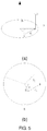
- seven candidate road models shown in FIG. 3 may be used for road segmentation.
- Road model includes most common road shape and may be used to predict next road region or boundary information.
- a near regional road straight line model may be used to establish a model-based road boundary detection algorithm. The use of this model is mainly base on: first, the straight line model is simple and owns less computation, which can effectively improve real-time performance of the detection method; second, the road boundary is approximately a straight line limited in near region, and the near region is a decision region of Intelligent Vehicle driving.
- a candidate road region is selected to perform regional growth and segmentation.
- the candidate region may have its boundary wider than the left and right road boundaries of the selected road model, respectively.
- the seed pixel may be obtained from a bottom and middle region of the preprocessed color image.
- the seed pixel may be deemed as belonging to a road region, because the bottom and middle region in the color image is generally road region closest to the vehicle in a real environment.
- FIG. 4 schematically illustrates a region of the color image in which region a seed pixel is identified, which is illustrated in a rectangle.
- the color image after being preprocessed has a height equal to 1, and a width equal to 1, where the height and width define the image in pixels.
- the rectangle may have 1/15 height and 1/2 width, where its bottom side is about 1/30 height from the image bottom, its top side is about 1/10 height from the image bottom, its left side is about 1/4 width from the image left side, and its right side is about 3/4 width from the image left side.
- a number N' of pixels in the region may be selected randomly as candidate seed pixels.
- the number N' may be an integer from 5 to 10.
- N' represents the number of candidate seed pixels selected in the bottom region
- S i ', C i ' are intermediate variables, respectively
- H t , S t , and I t represent values of hue, saturation and brightness of a pixel t in the number N' pixels, respectively; and, H i , S i
- the brightness threshold and color threshold are related to mean distances between pixels in the candidate region;
- M represents the number of pixels in the candidate road region
- d jchrom - i represents a color distance between a pixel j and the seed pixel i(H i , S i , I i )
- d j int- i represents an absolute value of a brightness distance between the
- T chrom 0 Kd c ⁇ h ⁇ r ⁇ o ⁇ m ⁇ - ⁇ r ⁇ m ⁇ s ⁇ - ⁇ i
- T achrom 0 Kd int- ⁇ r ⁇ m ⁇ s ⁇ - ⁇ i
- K represents an empirical parameter
- T achrom (0) represents a brightness threshold
- T chrom (0) represents a color threshold.
- the road regional growth may be performed to the candidate road region.
- the hue of a pixel may be unclear when its brightness is very high or low; further, the hue of a pixel may be unstable when its saturation is very low. Therefore, pixels in the image may be classified into pixels with dim color which may have brightness very high (e.g., I>90) or very low (e.g., I ⁇ 10) or saturation very low (e.g., S ⁇ 10), and pixels with bright color (pixels not included in dim regions). So when performing road regional growth, only brightness may be considered for pixels with dim color, and the three components H, S and I of the HSI color space should be all considered for pixels with bright color. In some embodiments, the dim color pixels' values of saturation S and brightness I may be normalized to [0, 100].
- a brightness distance between a pixel j and the seed pixel i is less than a brightness threshold
- the pixel j is classified into a road region, which may be expressed as in equation (17): I i ⁇ I j ⁇ T achrom where T achrom represents a brightness threshold, which may be obtained by the equation (16).
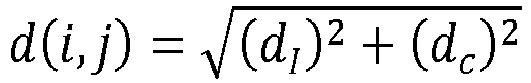
- d( i ,j) represents a spatial distance between a pixel j and the seed pixel i
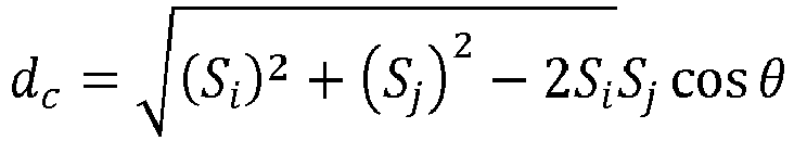
- d c represents a color distance between the pixel j and the seed pixel i in a two-dimensional color plane
- d I represents the absolute value of a brightness distance between the pixel j and the seed pixel i
- the pixel j may be classified into the road region, where T chrom may be obtained by the equation (15).
- pixels with dim color which do not meet equation (17) With respect to pixels with dim color which do not meet equation (17), and pixels with bright color which do not meet the condition that their d( i ,j) are greater than or equal to the color threshold, they are not classified into the road region. That is, those pixels are classified into non-road region. By doing this, all pixels in the road candidate region are segmented into road region and non-road region.
- An unstructured road may be captured in the color image. After the road segmentation in S111, a road segmentation result of the candidate road region is obtained. In some embodiments, to determine whether the selected road model matches the unstructured road, a matching degree of the selected road model with the unstructured road in the image may be calculated.
- a percentage of the number of pixels in a region according to the road segmentation result coinciding with pixies in corresponding region in the color image, within the number of all pixels in the corresponding region in the color image may be calculated.
- the coincidence of pixels means that one pixel may have its values of hue, saturation and brightness substantially equal to another pixel. If the percentage is greater than a predetermined value, the selected road model is determined to match the actual unstructured road. In some embodiments, the predetermined value may be in a range from 85% to 90%.
- the method goes to S105, a next road model within the seven road models is then tested, till a road model matching the unstructured road is determined.
- a percentage of the number of pixels in a region according to the estimation coinciding with pixies in a corresponding region in the color image, within the number of all pixels in the corresponding region in the color image may be calculated. If the percentage is greater than a predetermined value, e.g., 85%, the method goes to S115 to estimate the unstructured road's boundary in a second color image following the first image. That is, the road model which is determined previously still matches the actual unstructured road. Otherwise, the method goes to select a new road model matching the unstructured road.
- the seed pixel required for regional growth should be updated in real-time, in order to reflect changes in road appearance and brightness.
- the updated seed pixel may still be calculated based on a plurality of candidate seed pixels which are selected randomly from a bottom region of a color image.
- the brightness threshold T a chrom and the color threshold T chrom are also needs to be updated to perform regional growth, which may be expressed as T chrom (t) and T a chrom ( t ).
- a system for detecting an unstructured road boundary may be mounted on a vehicle.
- the system may include: a camera for obtaining a color image; a storing device for storing a plurality of candidate road models; and a processing device configured to select in the storing device a road model for an unstructured road; identify a seed pixel from the candidate road region; obtain a brightness threshold and a color threshold, where the brightness threshold and the color threshold are determined according to brightness distances and color distances from pixels in a candidate road region to the seed pixel; perform road segmentation by determining whether the pixels in the candidate road region belong to a road region based on the brightness threshold and the color threshold; determine whether the road model matches the unstructured road based on the road segmentation result; and estimate the unstructured road's boundary if the road model matches the unstructured road.
- the processing device may be configured to perform S101 to S115 and S201 to S217, to detect a road boundary of a color image captured by the camera.
- the above embodiments provide a real-time and effective unstructured road boundary detection method based on the HSI color space. Further, by using an improved vector median filtering method, the amount of computation can be reduced greatly.
Landscapes
- Engineering & Computer Science (AREA)
- Physics & Mathematics (AREA)
- General Physics & Mathematics (AREA)
- Theoretical Computer Science (AREA)
- Computer Vision & Pattern Recognition (AREA)
- Multimedia (AREA)
- Probability & Statistics with Applications (AREA)
- Software Systems (AREA)
- Image Analysis (AREA)
- Investigating Or Analysing Materials By Optical Means (AREA)
Claims (14)
- Verfahren zum Erkennen eines unstrukturierten Straßenrands, umfassend:Erhalten eines Farbbildes (S101);Umwandeln (S103) des Farbbildes in einen HIS-Farbraum;Auswählen (S105, S106) einer möglichen Straßenregion in dem Farbbild gemäß einem aus einer Vielzahl möglicher Straßenmodelle ausgewählten Straßenmodell;Identifizieren (S107) eines Ursprungspixels der möglichen Straßenregion;Erhalten eines Helligkeitsschwellenwerts und eines Farbschwellenwerts (S109), wobei der Helligkeitsschwellenwert und der Farbschwellenwert gemäß Helligkeitsabständen und Farbabständen von Pixeln in der möglichen Straßenregion zu dem Ursprungspixel bestimmt werden; undDurchführen (S111) einer Straßensegmentierung in der möglichen Straßenregion durch Bestimmen, ob die Pixel in der möglichen Straßenregion zu einer Straßenregion gehören, auf Grundlage des Helligkeitsschwellenwerts und des Farbschwellenwerts und Durchführen eines Straßenregionwachstums; undBestimmen (S113), dass das ausgewählte Straßenmodell einer unstrukturierten Straße entspricht, wenn ein Prozentanteil der Anzahl an Pixeln in dem Straßensegmentierungsergebnis zu der möglichen Straßenregion gehört;gekennzeichnet durch ein Vorverarbeiten des erhaltenen Farbbildes (S102), das Folgendes umfasst:Auswählen einer Probe (S203) aus dem Farbbild unter Verwendung eines Proberahmens, der eine vorher festgelegte Höhe und eine vorher festgelegte Breite aufweist;Berechnen von Normen für Vektoren (S205), die jeweils Pixeln in dem Proberahmen entsprechen, wobei jeder der Vektoren eine Linie wiedergibt, die von einem Ursprungspunkt zu einem Punkt zeigt, der einem Pixel in einem Farbraum entspricht;Identifizieren (S209) einer ersten vorher festgelegten Anzahl an Vektoren durch Herausfiltern einer ersten Anzahl an Vektoren, welche die höchsten Vektornormen aufweisen;Erhalten eines gewichteten Durchschnittsvektors (S211), wobei eine m-te Komponente des gewichteten Durchschnittsvektors erhalten wird, indem ein gewichteter Durchschnitt der m-ten Komponenten der ersten vorher festgelegten Anzahl an Vektoren berechnet wird;Berechnen (S213) von Normen für Differenzen zwischen der ersten vorher festgelegten Anzahl an Vektoren und dem gewichteten Durchschnittsvektor;Identifizieren (S215) einer zweiten vorher festgelegten Anzahl an Vektoren aus der ersten vorher festgelegten Anzahl an Vektoren, welche die kleinsten Normen von Differenzen mit dem gewichteten Durchschnittsvektor aufweisen; undErhalten von Medianvektoren (S217) auf Grundlage der zweiten vorher festgelegten Anzahl an Vektoren zum Erhalten eines vorverarbeiteten Farbbildes, wobei die mögliche Straßenregion in dem vorverarbeiteten Farbbild ausgewählt wird.
- Verfahren nach Anspruch 1, wobei ein Gewichtungswert für eine m-te Komponente der ersten vorher festgelegten Anzahl an Vektoren auf Grundlage eines Abstands zwischen einem Pixel, das der m-ten Komponente der ersten vorher festgelegten Anzahl an Vektoren entspricht, und der Mittelposition des Proberahmens bestimmt wird.
- Verfahren nach Anspruch 1, wobei ein Helligkeitsschwellenwert Tachrom und ein Farbschwellenwert Tchrom jeweils gemäß den folgenden Gleichungen erhalten werden:


- Verfahren nach Anspruch 3, wobei das Bestimmen, ob Pixel in der möglichen Straßenregion zu einer Straßenregion gehören, Folgendes umfasst:Erhalten eines räumlichen Abstands zwischen einem Pixel heller Farbe und dem Ursprungspixel;Vergleichen des räumlichen Abstands mit dem Farbabstand;Bestimmen, ob das Pixel der hellen Farbe zu einer Straßenregion gehört, gemäß dem Vergleich;wobei der räumliche Abstand zwischen dem Pixel und dem Ursprungspixel gemäß den folgenden Gleichungen berechnet wird:


- Verfahren nach Anspruch 3, wobei das Bestimmen, ob Pixel in einer möglichen Straßenregion zu einer Straßenregion gehören, Folgendes umfasst:Erhalten eines Helligkeitsabstands zwischen einem Pixel dunkler Farbe und dem Ursprungspixel;Vergleichen des Helligkeitsabstands mit dem Helligkeitsschwellenwert;Bestimmen, ob das Pixel dunkler Farbe zu einer Straßenregion gehört, gemäß dem Vergleich;wobei der Helligkeitsabstand zwischen dem Pixel j dunkler Farbe und dem Ursprungspixel i gemäß der folgenden Gleichung berechnet wird: di = Ii - Ij ,wobei Ii und Ij jeweils für Helligkeitskomponenten des Ursprungspixels i bzw. des Pixels j im HSI-Farbraum stehen.
- Verfahren nach Anspruch 1, ferner umfassend ein Bestimmen, ob das Straßenmodell einer unstrukturierten Straße entspricht, die in dem Farbbild enthalten ist, auf Grundlage eines Straßensegmentierungsergebnisses.
- Verfahren nach Anspruch 6, wobei das Bestimmen, ob das Straßenmodell der unstrukturierten Straße entspricht, auf Grundlage des Straßensegmentierungsergebnisses Folgendes umfasst:Berechnen eines Prozentanteils der Anzahl an Pixeln in einer Region gemäß dem Straßensegmentierungsergebnis, der sich mit Pixeln in einer entsprechenden Region in einem Farbbild deckt, in der Anzahl aller Pixel in der entsprechenden Region in dem Farbbild; undwenn der Prozentanteil größer als ein vorher festgelegter Wert ist, Bestimmen, dass das ausgewählte Straßenmodell der unstrukturierten Straße entspricht.
- System zum Erkennen eines unstrukturierten Straßenrands, umfassend:eine Kamera zum Erhalten eines Farbbildes; undeine Verarbeitungsvorrichtung, die zu Folgendem konfiguriert ist:Umwandeln (S103) des Farbbildes in einen HIS-Farbraum;Auswählen (S105, S106) einer möglichen Straßenregion in dem Farbbild gemäß einem aus einer Vielzahl von Straßenmodellen ausgewählten Straßenmodell;Identifizieren (S107) eines Ursprungspixels der möglichen Straßenregion;Erhalten eines Helligkeitsschwellenwerts und eines Farbschwellenwerts (S109), wobei der Helligkeitsschwellenwert und der Farbschwellenwert gemäß Helligkeitsabständen undFarbabständen von Pixeln in der möglichen Straßenregion zu dem Ursprungspixel bestimmt werden; undDurchführen (S111) einer Straßensegmentierung in der möglichen Straßenregion durch Bestimmen, ob die Pixel in der möglichen Straßenregion zu einer Straßenregion gehören, auf Grundlage des Helligkeitsschwellenwerts und des Farbschwellenwerts und Durchführen eines Straßenregionwachstums,Bestimmen (S113), dass das ausgewählte Straßenmodell einer unstrukturierten Straße entspricht, wenn ein Prozentanteil der Anzahl an Pixeln in dem Straßensegmentierungsergebnis zu der möglichen Straßenregion gehört;dadurch gekennzeichnet, dass die Verarbeitungsvorrichtung ferner zu Folgendem konfiguriert ist:Auswählen einer Probe (S203) aus dem Farbbild unter Verwendung eines Proberahmens, der eine vorher festgelegte Höhe und eine vorher festgelegte Breite aufweist;Berechnen von Normen für Vektoren (S205), die jeweils Pixeln in dem Proberahmen entsprechen, wobei jeder der Vektoren eine Linie wiedergibt, die von einem Ursprungspunkt zu einem Punkt zeigt, der einem Pixel in einem Farbraum entspricht;Identifizieren (S209) einer ersten vorher festgelegten Anzahl an Vektoren durch Herausfiltern einer ersten Anzahl an Vektoren, welche die höchsten Vektornormen aufweisen;Erhalten eines gewichteten Durchschnittsvektors (S211), wobei eine m-te Komponente des gewichteten Durchschnittsvektors erhalten wird, indem ein gewichteter Durchschnitt der m-ten Komponenten der ersten vorher festgelegten Anzahl an Vektoren berechnet wird;Berechnen (S213) von Normen für Differenzen zwischen der vorher festgelegten Anzahl an Vektoren und dem gewichteten Durchschnittsvektor;Identifizieren (S215) einer zweiten vorher festgelegten Anzahl an Vektoren aus der ersten vorher festgelegten Anzahl an Vektoren, welche die kleinsten Normen von Differenzen mit dem gewichteten Durchschnittsvektor aufweisen; undErhalten eines Medianvektors (S217) auf Grundlage der zweiten vorher festgelegten Anzahl an Vektoren zum Erhalten eines vorverarbeiteten Farbbildes, wobei die mögliche Straßenregion in dem vorverarbeiteten Farbbild ausgewählt wird.
- System nach Anspruch 8, wobei ein Gewichtungswert für eine m-te Komponente der ersten vorher festgelegten Anzahl an Vektoren auf Grundlage eines Abstands zwischen einem Pixel, das der m-ten Komponente der ersten vorher festgelegten Anzahl an Vektoren entspricht, und der Mittelposition des Proberahmens bestimmt wird.
- System nach Anspruch 8, wobei der Helligkeitsschwellenwert Tachrom und der Farbschwellenwert Tchrom jeweils gemäß den folgenden Gleichungen erhalten werden:


- System nach Anspruch 10, wobei die Verarbeitungsvorrichtung für das Bestimmen, ob ein Pixel j mit heller Farbe zu einer Straßenregion gehört, ferner zu Folgendem konfiguriert ist:Erhalten eines räumlichen Abstands zwischen einem Pixel heller Farbe und dem Ursprungspixel;Vergleichen des räumlichen Abstands mit dem Farbschwellenwert; undBestimmen, ob das Pixel heller Farbe zu einer Straßenregion gehört, gemäß dem Vergleich;wobei ein räumlicher Abstand zwischen dem Pixel j und dem Ursprungspixel gemäß den folgenden Gleichungen berechnet wird:


- System nach Anspruch 10, wobei die Verarbeitungsvorrichtung für das Bestimmen, ob ein Pixel j mit dunkler Farbe zu einer Straßenregion gehört, ferner zu Folgendem konfiguriert ist:Vergleichen des Helligkeitsabstands mit dem Helligkeitsschwellenwert; undBestimmen, ob das Pixel dunkler Farbe zu einer Straßenregion gehört, auf Grundlage des Vergleichs;wobei der Helligkeitsabstand zwischen dem Pixel j dunkler Farbe und dem Ursprungspixel i gemäß der folgenden Gleichung berechnet wird: di = Ii - Ij ,wobei Ii und Ij jeweils für Helligkeitskomponenten des Ursprungspixels i bzw. des Pixels j im HSI-Farbraum stehen.
- System nach Anspruch 8, wobei die Verarbeitungsvorrichtung ferner dazu konfiguriert ist, zu bestimmen, ob das Straßenmodell einer unstrukturierten Straße entspricht, die in dem Farbbild enthalten ist, auf Grundlage eines Straßensegmentierungsergebnisses.
- System nach Anspruch 13, wobei die Verarbeitungsvorrichtung für das Bestimmen, ob das Straßenmodell der unstrukturierten Straße entspricht, auf Grundlage des Straßensegmentierungsergebnisses ferner zu Folgendem konfiguriert ist:Berechnen eines Prozentanteils der Anzahl an Pixeln in einer Region gemäß dem Straßensegmentierungsergebnis, der sich mit Pixeln in einer entsprechenden Region in dem Farbbild deckt, in der Anzahl aller Pixel in der entsprechenden Region in dem Farbbild; undwenn der Prozentanteil größer als ein vorher festgelegter Wert ist, Bestimmen dass das ausgewählte Straßenmodell der unstrukturierten Straße entspricht.
Applications Claiming Priority (1)
| Application Number | Priority Date | Filing Date | Title |
|---|---|---|---|
| PCT/CN2013/082193 WO2015024257A1 (en) | 2013-08-23 | 2013-08-23 | Unstructured road boundary detection |
Publications (3)
| Publication Number | Publication Date |
|---|---|
| EP3036714A1 EP3036714A1 (de) | 2016-06-29 |
| EP3036714A4 EP3036714A4 (de) | 2017-05-10 |
| EP3036714B1 true EP3036714B1 (de) | 2019-12-04 |
Family
ID=52482989
Family Applications (1)
| Application Number | Title | Priority Date | Filing Date |
|---|---|---|---|
| EP13891976.6A Active EP3036714B1 (de) | 2013-08-23 | 2013-08-23 | Erkennung von unstrukturiertem strassenrand |
Country Status (4)
| Country | Link |
|---|---|
| US (1) | US9971944B2 (de) |
| EP (1) | EP3036714B1 (de) |
| CN (1) | CN105493141B (de) |
| WO (1) | WO2015024257A1 (de) |
Families Citing this family (14)
| Publication number | Priority date | Publication date | Assignee | Title |
|---|---|---|---|---|
| US9652814B2 (en) * | 2011-03-29 | 2017-05-16 | Jura Trade, Limited | Method and apparatus for generating and authenticating security documents |
| DE102012112104A1 (de) * | 2012-12-11 | 2014-06-12 | Conti Temic Microelectronic Gmbh | Verfahren und vorrichtung zur befahrbarkeitsanalyse |
| CN106156807B (zh) * | 2015-04-02 | 2020-06-02 | 华中科技大学 | 卷积神经网络模型的训练方法及装置 |
| CN106875422B (zh) * | 2017-02-06 | 2022-02-25 | 腾讯科技(上海)有限公司 | 人脸跟踪方法和装置 |
| EP3396370B1 (de) | 2017-04-28 | 2021-11-17 | Fujitsu Limited | Detektion von bereichen von interesse auf bildern |
| US10140530B1 (en) | 2017-08-09 | 2018-11-27 | Wipro Limited | Method and device for identifying path boundary for vehicle navigation |
| JP6971177B2 (ja) * | 2018-03-09 | 2021-11-24 | フォルシアクラリオン・エレクトロニクス株式会社 | 区画線認識装置 |
| US10976747B2 (en) | 2018-10-29 | 2021-04-13 | Here Global B.V. | Method and apparatus for generating a representation of an environment |
| KR102751284B1 (ko) * | 2019-08-12 | 2025-01-10 | 현대자동차주식회사 | 대화형 자율 주행 시스템 |
| CN111079637B (zh) * | 2019-12-12 | 2023-09-08 | 武汉轻工大学 | 田间图像中分割油菜花的方法、装置、设备及存储介质 |
| CN112172828B (zh) * | 2020-10-14 | 2022-03-08 | 斑马网络技术有限公司 | 窄路通行方法、装置、电子设备及计算机可读存储介质 |
| CN113313071A (zh) * | 2021-06-28 | 2021-08-27 | 浙江同善人工智能技术有限公司 | 一种道路区域识别方法及系统 |
| CN114926751B (zh) * | 2022-04-08 | 2025-06-13 | 广州市华南自然资源科学技术研究院 | 基于数据挖掘的农田道路提取阈值的选取方法及装置 |
| CN116091913A (zh) * | 2022-09-07 | 2023-05-09 | 武汉珈和科技有限公司 | 地块边界矢量识别方法、装置、设备及存储介质 |
Family Cites Families (9)
| Publication number | Priority date | Publication date | Assignee | Title |
|---|---|---|---|---|
| EP0488828B1 (de) * | 1990-11-30 | 1996-08-14 | Honda Giken Kogyo Kabushiki Kaisha | Steuervorrichtung für einen sich selbständig bewegenden Körper und Verfahren zur Auswertung der Daten davon |
| US8120652B2 (en) * | 1997-04-02 | 2012-02-21 | Gentex Corporation | System for controlling vehicle equipment |
| JP3807583B2 (ja) * | 1999-04-19 | 2006-08-09 | 本田技研工業株式会社 | 道路領域判定装置 |
| JP2001134769A (ja) * | 1999-11-04 | 2001-05-18 | Honda Motor Co Ltd | 対象物認識装置 |
| US7936903B2 (en) * | 2005-05-31 | 2011-05-03 | Koninklijke Philips Electronics N.V. | Method and a system for detecting a road at night |
| JP4567630B2 (ja) * | 2006-05-26 | 2010-10-20 | 富士通株式会社 | 車種判別プログラムおよび車種判別装置 |
| US8699754B2 (en) * | 2008-04-24 | 2014-04-15 | GM Global Technology Operations LLC | Clear path detection through road modeling |
| JP5188452B2 (ja) * | 2009-05-22 | 2013-04-24 | 富士重工業株式会社 | 道路形状認識装置 |
| CN101950415B (zh) | 2010-09-14 | 2011-11-16 | 武汉大学 | 一种基于形状语义模型约束的人脸超分辨率处理方法 |
-
2013
- 2013-08-23 US US14/909,951 patent/US9971944B2/en active Active
- 2013-08-23 CN CN201380079000.9A patent/CN105493141B/zh active Active
- 2013-08-23 WO PCT/CN2013/082193 patent/WO2015024257A1/en not_active Ceased
- 2013-08-23 EP EP13891976.6A patent/EP3036714B1/de active Active
Non-Patent Citations (1)
| Title |
|---|
| None * |
Also Published As
| Publication number | Publication date |
|---|---|
| CN105493141A (zh) | 2016-04-13 |
| US20160171314A1 (en) | 2016-06-16 |
| WO2015024257A1 (en) | 2015-02-26 |
| CN105493141B (zh) | 2018-09-14 |
| US9971944B2 (en) | 2018-05-15 |
| EP3036714A1 (de) | 2016-06-29 |
| WO2015024257A8 (en) | 2016-01-07 |
| EP3036714A4 (de) | 2017-05-10 |
Similar Documents
| Publication | Publication Date | Title |
|---|---|---|
| EP3036714B1 (de) | Erkennung von unstrukturiertem strassenrand | |
| EP3036730B1 (de) | Verkehrsampelerkennung | |
| CN102426649B (zh) | 一种简单的高准确率的钢印数字自动识别方法 | |
| EP2959454B1 (de) | Verfahren, system und softwaremodul zur vordergrundextraktion | |
| CN111881725B (zh) | 一种融合空频域特征的光学遥感图像船舶目标检测方法 | |
| US9811746B2 (en) | Method and system for detecting traffic lights | |
| CN109635758B (zh) | 智慧工地基于视频的高空作业人员安全带穿戴检测方法 | |
| CN103914708B (zh) | 基于机器视觉的食品品种检测方法及系统 | |
| Le et al. | Real time traffic sign detection using color and shape-based features | |
| CN112101260A (zh) | 一种作业人员安全带识别方法、装置、设备和存储介质 | |
| CN109492525B (zh) | 一种测量基站天线工程参数的方法 | |
| CN103955949A (zh) | 基于Mean-shift算法的运动目标检测方法 | |
| CN109063619A (zh) | 一种基于自适应背景抑制滤波器和组合方向梯度直方图的交通信号灯检测方法和系统 | |
| CN106815587B (zh) | 图像处理方法及装置 | |
| CN108154496B (zh) | 一种适用于电力作业机器人的电力设备外观变化识别方法 | |
| CN106447699B (zh) | 基于卡尔曼滤波的高铁接触网目标检测与跟踪方法 | |
| KR101026778B1 (ko) | 차량 영상 검지 장치 | |
| CN117876387A (zh) | 图像分割方法及装置 | |
| KR20130126386A (ko) | 적응적 피부색 검출 방법, 그리고 이를 이용한 얼굴 검출 방법 및 그 장치 | |
| CN106446832B (zh) | 一种基于视频的实时检测行人的方法 | |
| CN111402185B (zh) | 一种图像检测方法及装置 | |
| CN114463814B (zh) | 一种基于图像处理的快速证件照眼镜检测方法 | |
| CN107452008A (zh) | 图像边缘检测方法及装置 | |
| JPH07311833A (ja) | 人物の顔の検出装置 | |
| CN115100620B (zh) | 一种基于道路颜色和行驶方向的车道线拟合方法 |
Legal Events
| Date | Code | Title | Description |
|---|---|---|---|
| PUAI | Public reference made under article 153(3) epc to a published international application that has entered the european phase |
Free format text: ORIGINAL CODE: 0009012 |
|
| 17P | Request for examination filed |
Effective date: 20160121 |
|
| AK | Designated contracting states |
Kind code of ref document: A1 Designated state(s): AL AT BE BG CH CY CZ DE DK EE ES FI FR GB GR HR HU IE IS IT LI LT LU LV MC MK MT NL NO PL PT RO RS SE SI SK SM TR |
|
| AX | Request for extension of the european patent |
Extension state: BA ME |
|
| DAX | Request for extension of the european patent (deleted) | ||
| A4 | Supplementary search report drawn up and despatched |
Effective date: 20170410 |
|
| RIC1 | Information provided on ipc code assigned before grant |
Ipc: G06T 7/00 20170101AFI20170404BHEP Ipc: G06T 7/143 20170101ALI20170404BHEP Ipc: G06K 9/34 20060101ALI20170404BHEP Ipc: G06T 7/11 20170101ALI20170404BHEP Ipc: G06T 7/181 20170101ALI20170404BHEP Ipc: G06K 9/46 20060101ALI20170404BHEP Ipc: G06T 7/12 20170101ALI20170404BHEP Ipc: G06K 9/42 20060101ALI20170404BHEP Ipc: G06T 7/136 20170101ALI20170404BHEP Ipc: G06K 9/48 20060101ALI20170404BHEP Ipc: G06K 9/00 20060101ALI20170404BHEP |
|
| STAA | Information on the status of an ep patent application or granted ep patent |
Free format text: STATUS: EXAMINATION IS IN PROGRESS |
|
| 17Q | First examination report despatched |
Effective date: 20180709 |
|
| GRAP | Despatch of communication of intention to grant a patent |
Free format text: ORIGINAL CODE: EPIDOSNIGR1 |
|
| STAA | Information on the status of an ep patent application or granted ep patent |
Free format text: STATUS: GRANT OF PATENT IS INTENDED |
|
| INTG | Intention to grant announced |
Effective date: 20190926 |
|
| GRAS | Grant fee paid |
Free format text: ORIGINAL CODE: EPIDOSNIGR3 |
|
| GRAA | (expected) grant |
Free format text: ORIGINAL CODE: 0009210 |
|
| STAA | Information on the status of an ep patent application or granted ep patent |
Free format text: STATUS: THE PATENT HAS BEEN GRANTED |
|
| AK | Designated contracting states |
Kind code of ref document: B1 Designated state(s): AL AT BE BG CH CY CZ DE DK EE ES FI FR GB GR HR HU IE IS IT LI LT LU LV MC MK MT NL NO PL PT RO RS SE SI SK SM TR |
|
| REG | Reference to a national code |
Ref country code: GB Ref legal event code: FG4D |
|
| REG | Reference to a national code |
Ref country code: CH Ref legal event code: EP |
|
| REG | Reference to a national code |
Ref country code: AT Ref legal event code: REF Ref document number: 1210328 Country of ref document: AT Kind code of ref document: T Effective date: 20191215 |
|
| REG | Reference to a national code |
Ref country code: DE Ref legal event code: R096 Ref document number: 602013063763 Country of ref document: DE |
|
| REG | Reference to a national code |
Ref country code: IE Ref legal event code: FG4D |
|
| REG | Reference to a national code |
Ref country code: NL Ref legal event code: MP Effective date: 20191204 |
|
| REG | Reference to a national code |
Ref country code: LT Ref legal event code: MG4D |
|
| PG25 | Lapsed in a contracting state [announced via postgrant information from national office to epo] |
Ref country code: NO Free format text: LAPSE BECAUSE OF FAILURE TO SUBMIT A TRANSLATION OF THE DESCRIPTION OR TO PAY THE FEE WITHIN THE PRESCRIBED TIME-LIMIT Effective date: 20200304 Ref country code: GR Free format text: LAPSE BECAUSE OF FAILURE TO SUBMIT A TRANSLATION OF THE DESCRIPTION OR TO PAY THE FEE WITHIN THE PRESCRIBED TIME-LIMIT Effective date: 20200305 Ref country code: LT Free format text: LAPSE BECAUSE OF FAILURE TO SUBMIT A TRANSLATION OF THE DESCRIPTION OR TO PAY THE FEE WITHIN THE PRESCRIBED TIME-LIMIT Effective date: 20191204 Ref country code: SE Free format text: LAPSE BECAUSE OF FAILURE TO SUBMIT A TRANSLATION OF THE DESCRIPTION OR TO PAY THE FEE WITHIN THE PRESCRIBED TIME-LIMIT Effective date: 20191204 Ref country code: LV Free format text: LAPSE BECAUSE OF FAILURE TO SUBMIT A TRANSLATION OF THE DESCRIPTION OR TO PAY THE FEE WITHIN THE PRESCRIBED TIME-LIMIT Effective date: 20191204 Ref country code: FI Free format text: LAPSE BECAUSE OF FAILURE TO SUBMIT A TRANSLATION OF THE DESCRIPTION OR TO PAY THE FEE WITHIN THE PRESCRIBED TIME-LIMIT Effective date: 20191204 Ref country code: BG Free format text: LAPSE BECAUSE OF FAILURE TO SUBMIT A TRANSLATION OF THE DESCRIPTION OR TO PAY THE FEE WITHIN THE PRESCRIBED TIME-LIMIT Effective date: 20200304 |
|
| PG25 | Lapsed in a contracting state [announced via postgrant information from national office to epo] |
Ref country code: RS Free format text: LAPSE BECAUSE OF FAILURE TO SUBMIT A TRANSLATION OF THE DESCRIPTION OR TO PAY THE FEE WITHIN THE PRESCRIBED TIME-LIMIT Effective date: 20191204 Ref country code: HR Free format text: LAPSE BECAUSE OF FAILURE TO SUBMIT A TRANSLATION OF THE DESCRIPTION OR TO PAY THE FEE WITHIN THE PRESCRIBED TIME-LIMIT Effective date: 20191204 |
|
| PG25 | Lapsed in a contracting state [announced via postgrant information from national office to epo] |
Ref country code: AL Free format text: LAPSE BECAUSE OF FAILURE TO SUBMIT A TRANSLATION OF THE DESCRIPTION OR TO PAY THE FEE WITHIN THE PRESCRIBED TIME-LIMIT Effective date: 20191204 |
|
| PG25 | Lapsed in a contracting state [announced via postgrant information from national office to epo] |
Ref country code: ES Free format text: LAPSE BECAUSE OF FAILURE TO SUBMIT A TRANSLATION OF THE DESCRIPTION OR TO PAY THE FEE WITHIN THE PRESCRIBED TIME-LIMIT Effective date: 20191204 Ref country code: PT Free format text: LAPSE BECAUSE OF FAILURE TO SUBMIT A TRANSLATION OF THE DESCRIPTION OR TO PAY THE FEE WITHIN THE PRESCRIBED TIME-LIMIT Effective date: 20200429 Ref country code: EE Free format text: LAPSE BECAUSE OF FAILURE TO SUBMIT A TRANSLATION OF THE DESCRIPTION OR TO PAY THE FEE WITHIN THE PRESCRIBED TIME-LIMIT Effective date: 20191204 Ref country code: CZ Free format text: LAPSE BECAUSE OF FAILURE TO SUBMIT A TRANSLATION OF THE DESCRIPTION OR TO PAY THE FEE WITHIN THE PRESCRIBED TIME-LIMIT Effective date: 20191204 Ref country code: RO Free format text: LAPSE BECAUSE OF FAILURE TO SUBMIT A TRANSLATION OF THE DESCRIPTION OR TO PAY THE FEE WITHIN THE PRESCRIBED TIME-LIMIT Effective date: 20191204 Ref country code: NL Free format text: LAPSE BECAUSE OF FAILURE TO SUBMIT A TRANSLATION OF THE DESCRIPTION OR TO PAY THE FEE WITHIN THE PRESCRIBED TIME-LIMIT Effective date: 20191204 |
|
| PG25 | Lapsed in a contracting state [announced via postgrant information from national office to epo] |
Ref country code: IS Free format text: LAPSE BECAUSE OF FAILURE TO SUBMIT A TRANSLATION OF THE DESCRIPTION OR TO PAY THE FEE WITHIN THE PRESCRIBED TIME-LIMIT Effective date: 20200404 Ref country code: SK Free format text: LAPSE BECAUSE OF FAILURE TO SUBMIT A TRANSLATION OF THE DESCRIPTION OR TO PAY THE FEE WITHIN THE PRESCRIBED TIME-LIMIT Effective date: 20191204 Ref country code: SM Free format text: LAPSE BECAUSE OF FAILURE TO SUBMIT A TRANSLATION OF THE DESCRIPTION OR TO PAY THE FEE WITHIN THE PRESCRIBED TIME-LIMIT Effective date: 20191204 |
|
| REG | Reference to a national code |
Ref country code: DE Ref legal event code: R097 Ref document number: 602013063763 Country of ref document: DE |
|
| REG | Reference to a national code |
Ref country code: AT Ref legal event code: MK05 Ref document number: 1210328 Country of ref document: AT Kind code of ref document: T Effective date: 20191204 |
|
| PLBE | No opposition filed within time limit |
Free format text: ORIGINAL CODE: 0009261 |
|
| STAA | Information on the status of an ep patent application or granted ep patent |
Free format text: STATUS: NO OPPOSITION FILED WITHIN TIME LIMIT |
|
| PG25 | Lapsed in a contracting state [announced via postgrant information from national office to epo] |
Ref country code: DK Free format text: LAPSE BECAUSE OF FAILURE TO SUBMIT A TRANSLATION OF THE DESCRIPTION OR TO PAY THE FEE WITHIN THE PRESCRIBED TIME-LIMIT Effective date: 20191204 |
|
| 26N | No opposition filed |
Effective date: 20200907 |
|
| PG25 | Lapsed in a contracting state [announced via postgrant information from national office to epo] |
Ref country code: PL Free format text: LAPSE BECAUSE OF FAILURE TO SUBMIT A TRANSLATION OF THE DESCRIPTION OR TO PAY THE FEE WITHIN THE PRESCRIBED TIME-LIMIT Effective date: 20191204 Ref country code: SI Free format text: LAPSE BECAUSE OF FAILURE TO SUBMIT A TRANSLATION OF THE DESCRIPTION OR TO PAY THE FEE WITHIN THE PRESCRIBED TIME-LIMIT Effective date: 20191204 Ref country code: AT Free format text: LAPSE BECAUSE OF FAILURE TO SUBMIT A TRANSLATION OF THE DESCRIPTION OR TO PAY THE FEE WITHIN THE PRESCRIBED TIME-LIMIT Effective date: 20191204 |
|
| PG25 | Lapsed in a contracting state [announced via postgrant information from national office to epo] |
Ref country code: IT Free format text: LAPSE BECAUSE OF FAILURE TO SUBMIT A TRANSLATION OF THE DESCRIPTION OR TO PAY THE FEE WITHIN THE PRESCRIBED TIME-LIMIT Effective date: 20191204 |
|
| PG25 | Lapsed in a contracting state [announced via postgrant information from national office to epo] |
Ref country code: MC Free format text: LAPSE BECAUSE OF FAILURE TO SUBMIT A TRANSLATION OF THE DESCRIPTION OR TO PAY THE FEE WITHIN THE PRESCRIBED TIME-LIMIT Effective date: 20191204 |
|
| REG | Reference to a national code |
Ref country code: CH Ref legal event code: PL |
|
| GBPC | Gb: european patent ceased through non-payment of renewal fee |
Effective date: 20200823 |
|
| PG25 | Lapsed in a contracting state [announced via postgrant information from national office to epo] |
Ref country code: CH Free format text: LAPSE BECAUSE OF NON-PAYMENT OF DUE FEES Effective date: 20200831 Ref country code: LI Free format text: LAPSE BECAUSE OF NON-PAYMENT OF DUE FEES Effective date: 20200831 Ref country code: LU Free format text: LAPSE BECAUSE OF NON-PAYMENT OF DUE FEES Effective date: 20200823 |
|
| REG | Reference to a national code |
Ref country code: BE Ref legal event code: MM Effective date: 20200831 |
|
| PG25 | Lapsed in a contracting state [announced via postgrant information from national office to epo] |
Ref country code: FR Free format text: LAPSE BECAUSE OF NON-PAYMENT OF DUE FEES Effective date: 20200831 |
|
| PG25 | Lapsed in a contracting state [announced via postgrant information from national office to epo] |
Ref country code: GB Free format text: LAPSE BECAUSE OF NON-PAYMENT OF DUE FEES Effective date: 20200823 Ref country code: IE Free format text: LAPSE BECAUSE OF NON-PAYMENT OF DUE FEES Effective date: 20200823 Ref country code: BE Free format text: LAPSE BECAUSE OF NON-PAYMENT OF DUE FEES Effective date: 20200831 |
|
| PG25 | Lapsed in a contracting state [announced via postgrant information from national office to epo] |
Ref country code: TR Free format text: LAPSE BECAUSE OF FAILURE TO SUBMIT A TRANSLATION OF THE DESCRIPTION OR TO PAY THE FEE WITHIN THE PRESCRIBED TIME-LIMIT Effective date: 20191204 Ref country code: MT Free format text: LAPSE BECAUSE OF FAILURE TO SUBMIT A TRANSLATION OF THE DESCRIPTION OR TO PAY THE FEE WITHIN THE PRESCRIBED TIME-LIMIT Effective date: 20191204 Ref country code: CY Free format text: LAPSE BECAUSE OF FAILURE TO SUBMIT A TRANSLATION OF THE DESCRIPTION OR TO PAY THE FEE WITHIN THE PRESCRIBED TIME-LIMIT Effective date: 20191204 |
|
| PG25 | Lapsed in a contracting state [announced via postgrant information from national office to epo] |
Ref country code: MK Free format text: LAPSE BECAUSE OF FAILURE TO SUBMIT A TRANSLATION OF THE DESCRIPTION OR TO PAY THE FEE WITHIN THE PRESCRIBED TIME-LIMIT Effective date: 20191204 |
|
| P01 | Opt-out of the competence of the unified patent court (upc) registered |
Effective date: 20230527 |
|
| PGFP | Annual fee paid to national office [announced via postgrant information from national office to epo] |
Ref country code: DE Payment date: 20250724 Year of fee payment: 13 |