EP3036730B1 - Détection de feux de circulation - Google Patents
Détection de feux de circulation Download PDFInfo
- Publication number
- EP3036730B1 EP3036730B1 EP13891786.9A EP13891786A EP3036730B1 EP 3036730 B1 EP3036730 B1 EP 3036730B1 EP 13891786 A EP13891786 A EP 13891786A EP 3036730 B1 EP3036730 B1 EP 3036730B1
- Authority
- EP
- European Patent Office
- Prior art keywords
- pixels
- blobs
- candidate
- pixel
- traffic light
- Prior art date
- Legal status (The legal status is an assumption and is not a legal conclusion. Google has not performed a legal analysis and makes no representation as to the accuracy of the status listed.)
- Active
Links
Images


Classifications
-
- G—PHYSICS
- G08—SIGNALLING
- G08G—TRAFFIC CONTROL SYSTEMS
- G08G1/00—Traffic control systems for road vehicles
- G08G1/09—Arrangements for giving variable traffic instructions
- G08G1/0962—Arrangements for giving variable traffic instructions having an indicator mounted inside the vehicle, e.g. giving voice messages
- G08G1/09623—Systems involving the acquisition of information from passive traffic signs by means mounted on the vehicle
-
- G—PHYSICS
- G06—COMPUTING OR CALCULATING; COUNTING
- G06F—ELECTRIC DIGITAL DATA PROCESSING
- G06F18/00—Pattern recognition
- G06F18/20—Analysing
- G06F18/24—Classification techniques
-
- G—PHYSICS
- G06—COMPUTING OR CALCULATING; COUNTING
- G06T—IMAGE DATA PROCESSING OR GENERATION, IN GENERAL
- G06T7/00—Image analysis
- G06T7/90—Determination of colour characteristics
-
- G—PHYSICS
- G06—COMPUTING OR CALCULATING; COUNTING
- G06V—IMAGE OR VIDEO RECOGNITION OR UNDERSTANDING
- G06V20/00—Scenes; Scene-specific elements
- G06V20/50—Context or environment of the image
- G06V20/56—Context or environment of the image exterior to a vehicle by using sensors mounted on the vehicle
- G06V20/58—Recognition of moving objects or obstacles, e.g. vehicles or pedestrians; Recognition of traffic objects, e.g. traffic signs, traffic lights or roads
- G06V20/582—Recognition of moving objects or obstacles, e.g. vehicles or pedestrians; Recognition of traffic objects, e.g. traffic signs, traffic lights or roads of traffic signs
-
- G—PHYSICS
- G06—COMPUTING OR CALCULATING; COUNTING
- G06V—IMAGE OR VIDEO RECOGNITION OR UNDERSTANDING
- G06V20/00—Scenes; Scene-specific elements
- G06V20/50—Context or environment of the image
- G06V20/56—Context or environment of the image exterior to a vehicle by using sensors mounted on the vehicle
- G06V20/58—Recognition of moving objects or obstacles, e.g. vehicles or pedestrians; Recognition of traffic objects, e.g. traffic signs, traffic lights or roads
- G06V20/584—Recognition of moving objects or obstacles, e.g. vehicles or pedestrians; Recognition of traffic objects, e.g. traffic signs, traffic lights or roads of vehicle lights or traffic lights
-
- G—PHYSICS
- G06—COMPUTING OR CALCULATING; COUNTING
- G06T—IMAGE DATA PROCESSING OR GENERATION, IN GENERAL
- G06T2207/00—Indexing scheme for image analysis or image enhancement
- G06T2207/10—Image acquisition modality
- G06T2207/10024—Color image
-
- G—PHYSICS
- G06—COMPUTING OR CALCULATING; COUNTING
- G06T—IMAGE DATA PROCESSING OR GENERATION, IN GENERAL
- G06T2207/00—Indexing scheme for image analysis or image enhancement
- G06T2207/30—Subject of image; Context of image processing
- G06T2207/30248—Vehicle exterior or interior
- G06T2207/30252—Vehicle exterior; Vicinity of vehicle
Definitions
- the present disclosure generally relates to traffic light detection.
- Traffic light detection is more and more widely used in driving assistance systems.
- traffic lights are detected based on color segmentation and template matching.
- a method for traffic light detection includes obtaining a color image; calculating pixel response values for pixels of the color image, respectively, where each pixel response value is be calculated using R, G, and B values of the corresponding pixel; identifying pixels whose pixel response values are distributed on the first side or the second side of a predetermined range in a pixel response value distribution as candidate pixels; identifying candidate blobs based on the candidate pixels; and verifying whether the candidate blobs are traffic lights; the method is further characterized in that each pixel response value is calculated by multiplying a first value and a second value for the corresponding pixel, where the first value is a sum of the three weighted components R, G and B of the corresponding pixel, the weight applied on the R component having a first sign and the respective weights applied on the G and B components having the opposite sign, and the second value is a sum of the two weighted components R and G of the corresponding pixel, the two weights having the same sign.
- pixel response values of pixels other than red traffic light pixels and green traffic light pixels are substantially distributed within the predetermined range.
- identifying the candidate blobs may include: identifying a first set of blobs based on the candidate pixels; and identifying the candidate blobs from the first set of blobs, where each of the first set of blobs may be determined whether or not a member of the candidate blobs based on pixel response values of its pixels and its surrounding pixels, such that false positives may be further reduced.
- a system for traffic light detection is provided.
- the system is set out in claim 3.
- Traffic light detection may be based on image processing technology. Candidates for a traffic light on an image may need to be verified whether or not a true traffic light. Normally, such verification may be implemented using a traffic light classifier, such as a cascade detector or a support vector machine, which may lead a large computation load. Therefore, to improve efficiency and reliability of traffic light detection, before the verification, segments in the color image which are not likely to be a traffic light need to be filtered out as many as possible, meanwhile, it should be ensured that segments in the color image which are likely to be a traffic light may not be filtered out. A balance between efficiency and reliability is a major concern in traffic light detection.
- a traffic light classifier such as a cascade detector or a support vector machine
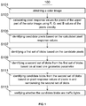
- FIG. 1 schematically illustrates a flow chart of a method 100 for traffic light detection according to one embodiment.
- the color image may be captured by a camera.
- the camera may be mounted on a vehicle.
- color images may be captured at evenly spaced time points, and may be processed one by one successively.
- FIG. 2 illustrates an example color image captured by a camera mounted on a vehicle.
- the color image is captured at an intersection. It could be seen from the color image that, many objects may have a color close to a traffic light at the intersection, such as trees, vehicle taillights, billboard lights, red or green logos, which may be false positives after verification by a conventional traffic light classifier. These false positives may need to be filtered out as many as possible.
- a lower part of the color image may be removed to improve the efficiency, since generally a traffic light may not appear in the lower part. As a result, the rest upper part of the color image is remained for subsequent processing.
- FIG. 3 illustrates an upper part of the color image of FIG. 2 . It should be noted that removing the low part of the color image may be optional.
- pixel response values of pixels other than the red traffic light pixels and green traffic light pixels may be substantially distributed in a predetermined range
- pixel response values of the red traffic light pixels may be substantially distributed on a first side of the predetermined range
- pixel response values of the green traffic light pixels may be substantially distributed on a second side of the predetermined range, where the second side is opposite to the first side.
- each of the pixel response values may be calculated based on two components of a corresponding pixel, where a first component may indicate a tendency that whether the corresponding pixel is more like a green traffic light pixel, a red traffic light pixel or a pixel other than a traffic light, i.e., a tendency towards the first side, the second side or the predetermined range; and the second component may be able to amplify the tendency if the tendency is substantially towards the first side or the second side.
- the pixel response value may calculated based on multiplication of the first and second components.
- traffic light pixels should be outstanding in certain color channel values, compared with other objects.
- a red traffic light pixel may have a relatively high red channel (R) value, but very low green channel (G) value and blue channel (B) value; while a green traffic light pixel may have relatively high G value and B value, but very low R value.
- Pixels other than a traffic light pixel may have R, G and B values closer with each other. Therefore, R, G and B values may be used to separate red traffic light pixels, green traffic light pixels and pixels of other objects apart, thus can be used to calculate the first component.
- the first component may be calculated based on summation of a third, a fourth, and a fifth components which are respectively based on R, G and B values of the corresponding pixel, where the third component may have a first sign, and the fourth and fifth components may have a second sign which is opposite to the first sign.
- the first components of a red traffic light pixel and a green traffic light pixel may be towards opposite sides.
- the third component may be k 1 ⁇ R
- the fourth component may be -k 2 ⁇ G
- the fifth component may be -k 3 ⁇ B, where ki, k 2 and k 3 are set such that the tendency is substantially towards the first side if the corresponding pixel is a red traffic light pixel and the tendency is substantially towards the second side if the corresponding pixel is a green traffic light pixel.
- the weight factors ki, k 2 and k 3 may be adjusted based on ambient lights, camera parameters, etc.
- the first component may be R ⁇ G + B 2 . Therefore, based on whether the first component is positive or negative, whether the pixel is more likely to be a red traffic light pixel or a green traffic light pixel may be conveniently determined. Further, the larger the absolute value of the first component is, the more possible the pixel could be a traffic light pixel.
- the second component may be used to amplify the disparity between pixel response values of the red traffic light pixels and pixel response values of the green traffic light pixels.
- the method may be more robust if this disparity is enlarged.
- the traffic light pixels either red or green, may not only be pure in a traffic light color, but also have relatively high luminosity. Therefore, in some embodiments, the second component may represent the luminosity of the corresponding pixel, which is a suitable way to amplify the tendency. As a result, objects which are red or green, but dark, such as tree leaves, may be filtered out.
- the luminosity of the pixel may be highly relevant to the R, G and B values. Therefore, the second component may also be represented using the R, G and B values.
- the second component may be calculated based on summation of a sixth and a seventh components which are respectively based on R and G values of the corresponding pixel, where the sixth and the seventh components have the same sign.
- the sixth component may be k 4 ⁇ R and the seventh component may be k 5 ⁇ G, where k 4 and k 5 are set such that the pixel response value is substantially on the first side if the corresponding pixel is a red traffic light pixel, and the pixel response value is substantially on the second side if the corresponding pixel is a green traffic light pixel.
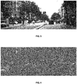
- FIG. 4 schematically illustrates pixel response values of pixels in FIG. 3 calculated based on Equation (1).
- the pixel response values are converted into grayscales. It could be seen from FIG. 4 that the red traffic light pixels are relatively light while the green traffic light pixels are relatively dark. It should be noted that FIG. 4 is merely for illustration. In a practical process, there is no need to form an image for illustrating the pixel response values.
- the pixel response values of the red traffic light pixels, the pixel response values of the green traffic light pixels and the pixel response values of other pixels may be distributed into separated ranges. Therefore, candidate pixels for a red traffic light or a green traffic light may be identified based on the pixel response values.
- the pixel response values were calculated based on Equation (1) and were normalized to [0, 1].
- pixels having a pixel response value within a predetermined range from -0.25 to 0.375 were identified as pixels other than a traffic light
- pixels having a pixel response value at a first side of the predetermined range, i.e., larger than 0.375 were identified as red traffic light candidate pixels
- pixels having a pixel response value at a second side of the predetermined range, i.e., less than -0.25 were identified as green traffic light candidate pixels.
- the specific range is merely an example and can be adjusted based on camera parameters, etc.
- FIG. 5 schematically illustrates candidate pixels in the color image of FIG. 3 .
- the red traffic light candidate pixels and the green traffic light candidate pixels are marked.
- FIG. 5 is given for illustration only. In practical processing, it is not necessary to obtain an image like FIG. 5 to visibly show the candidate pixels.
- the first set of blobs may be identified using connected component labeling.
- the first set of blobs may include blobs identified based on the red traffic light candidate pixels which are to be subject to red traffic light detection, and blobs identified based on the green traffic light candidate pixels which are to be subject to green traffic light detection.
- red traffic light detection and green traffic light detection can be performed either in parallel or in serial.
- the red traffic light detection and green traffic light detection are performed in parallel as an example.
- the first set of blobs may be taken as candidate blobs to be verified using a traffic light detector or classifier.
- false positives in the first set of blobs may be further filtered out, so that the verifications of the candidate blobs, which normally take the most computation resource, may be reduced.
- further filtering out false positives may be further filtered out.
- blob analysis based on at least one geometric parameter may be used to filter out some blobs which are not likely to be a traffic light based on their shapes and/or sizes.
- the remaining blobs may be identified as the second set of blobs.
- Minimum enclosing shapes respectively encompassing blobs of the first set may be defined in the blob analysis for facilitating analyzing.
- FIG. 6 schematically illustrates a first example blob of the first set of blobs and its minimum enclosing shape.
- the minimum enclosing shapes may be rectangles.
- the at least one geometric parameter may be a pixel number.
- the first example blob has a pixel number lager than 255, it may be filtered out because a traffic light should not be too large.
- specific value of the criterion may be altered based on factors like image resolution. When the image resolution is 720 ⁇ 480, the above proposed number 255 may be suitable. A suitable value of this criterion may increase or decrease with the increase or decrease of the image resolution.
- the at least one geometric parameter may be the width or height of the blob.
- a width and a height of the minimum enclosing shape may be taken as the width and height of the first example blob, and if the first example blob has a width or height larger than 24, it may be filtered out. It should be noted that the value of the width or height criterion may also change with the image resolution.
- the at least one geometric parameter may be a width to height ratio. Since normally a traffic light should be round, its corresponding blob may have a minimum enclosing rectangle close to a square. For example, if the first example blob has a width to height ratio beyond a range from about 0.5 to 2, it may be filtered out.
- Each of the blobs of the second set may be determined whether or not a member of the candidate blobs base on pixel response values of its pixels and surroundings. False positives may be reduced, because normally a traffic light should not only be bright and pure in the traffic light color itself, but also be prominent among its local surroundings, which means the traffic light blob may have be outstanding in pixel response values.
- FIG. 7 schematically illustrates a flow chart of a process 200 for identifying the candidate blobs from the second set of blobs according to one embodiment.
- the ego segment may substantially encompass the second example blob.
- the ego segment may be a minimum enclosing rectangle of the second example blob.
- minimum enclosing rectangles were defined during the blob analysis in S109, so S201 may be avoided.
- the ego segment response value may be calculated based on summation of pixel response values of pixels in the ego segment.
- ⁇ stands for the ego segment response value
- pr(x,y) stands for the pixel response value of a pixel in ego segment having an image coordinate (x,y)
- y m and y n stand for upmost and lowest coordinates of the ego segment on a y axis, respectively
- x i and x j stand for leftmost and rightmost coordinates of the ego segment on a x axis, respectively.
- whether the second example blob is a false positive may be determined. Specifically, if the ego segment response value and the pixel response values of pixels in the second example blob are not on the same side of the predetermined range, the second example blob may be filtered out. Therefore, false positives may be further filtered out, especially for some objects like red and/or green characters, logos, and the like, which may have extreme pixel response values and hardly be filtered out in the blob analysis. Besides, following computations for these false positives may be avoided.
- each of the ambient segments may have a same shape and size with the ego segment.
- FIG. 8 schematically illustrates the second example blob and an example of its ego segment and ambient segments.
- a minimum enclosing rectangle (windowed with heavy lines) which is defined as the ego segment of the second example blob.
- Eight rectangles having a same shape and size as the minimum enclosing rectangle are defined as the ambient segments.
- c 0 to cs are center points of the ego segment and the ambient segments.
- the eight ambient segments are a 1 a 3 C 0 a 15 , a2a4C4Cs, a 3 a 5 a 7 c 0 , C 2 a 6 a 8 C 6 , c 0 a 7 a 9 a 11 , c 8 c 4 a 10 a 12 , a 15 c 0 a 11 a 13 , and a 16 c 2 c 6 a 14 .
- Each of the ambient segment response values may be calculated based on pixel response values of pixels in a corresponding ambient segment. For example, summation of the pixel response values may be calculated.
- whether the second example blob is a false positive may be determined based on its ego segment response value and ambient segment response value. For example, if the pixel response values were calculated based on the above Equation (1), the ego segment response value of the second example blob should be larger than any of its ambient segment response values if its pixels are red traffic light pixels, vice versa, or else, the second example blob may be filtered out.
- the blobs for red traffic light and green traffic light are respectively sorted decreasingly based on the probability values, where top 20 blobs for red traffic light and top 30 blobs for green traffic light are selected as the candidate blobs.
- a relatively small number of blobs may be selected as the candidate blobs. False positives may be reduced and processing speed may be increased.
- a traffic light detector or classifier such as template matching, neural network, support vector machine (SVM), cascade detector, and the like, whether a region corresponding to a candidate blob represents a traffic light may be determined. In some embodiments, regions in the color image corresponding to the candidate blobs may be verified. In some embodiments, regions in a grayscale image converted from the color image corresponding to the candidate blobs may be verified. As stated above, based on the above processing, a relatively small number of candidate blobs may be remained, thereby improving both the reliability and efficiency.
- SVM support vector machine
- regions corresponding to the candidate blobs may be segmented in the color image firstly. Segmenting the regions may be implemented based on positions, sizes and types of the candidate blobs, and a traffic light template.
- the candidate blob for a red traffic light should be located on top of the corresponding region
- the candidate blob for a green traffic light should be located on bottom of the corresponding region
- the corresponding region may have a width equaling to or a little larger than that of the blob and a height more than three times of that of the blob.
- the candidate blob for a red traffic light should be located on left of the corresponding region
- the candidate blob for a green traffic light should be located on right of the corresponding region
- the corresponding region may have a width at least three times of that of the blob and a height equaling to or a little larger than that of the blob.
- the corresponding regions may be enlarged to ensure that they can cover the traffic light(s) in the color image.
- FIG. 9 illustrates rectangle regions in the color image of FIG. 2 corresponding to the candidate blobs.
- the rectangle regions corresponding to the candidate blobs for red and green traffic lights are marked. It could be seen from FIG. 9 that false positives may still exist. Thereafter, these rectangle regions may be verified using a traffic light detector or classifier.
- the traffic light detector may include a cascade detector and a SVM.
- the cascade detector may be used prior to the SVM, since the SVM takes more time than the cascade detector.
- the rectangle regions in the color image may be converted into monochrome images before being verified by the traffic light detector.
- a result may be output by framing the identified traffic light(s), such as illustrated in FIG. 10 .
- a system for traffic light detection may include a processing device configured to: obtain a color image; calculate pixel response values for pixels of the upper part of the color image using R, G, and B values of the pixels directly; identify candidate pixels based on the calculated pixel response values; identify a first set of blobs based on the candidate pixels; identify a second set of blobs from the first set of blobs based on at least one geometric parameter; identify candidate blobs from the second set of blobs based on pixel response values of pixels in and surrounding the second set of blobs; and verify whether the candidate blobs are traffic lights.
- Specific configurations of the processing device may be found by referring S101 to S113 above, which may not be illustrated in detail here.
- a system for traffic light detection may include: means for calculating pixel response values for pixels of a color image, respectively, where each of the pixel response values may be calculated using R, G, and B values of a corresponding pixel directly, such that pixel response values of red traffic light pixels are substantially distributed on a first side of a predetermined range and pixel response values of green traffic light pixels are substantially distributed on a second side of the predetermined range which is opposite to the first side; means for identifying pixels whose pixel response values are distributed on the first side or the second side as candidate pixels; means for identifying candidate blobs based on the candidate pixels; and means for verifying whether the candidate blobs are traffic lights.
- a non-transitory computer readable medium which contains a computer program for traffic light detection.
- the computer program When the computer program is executed by a processor, it will instruct the processor to: calculate pixel response values for pixels of a color image, respectively, where each of the pixel response values may be calculated using R, G, and B values of a corresponding pixel directly, such that pixel response values of red traffic light pixels are substantially distributed on a first side of a predetermined range and pixel response values of green traffic light pixels are substantially distributed on a second side of the predetermined range which is opposite to the first side; identify pixels whose pixel response values are distributed on the first side or the second side as candidate pixels; identify candidate blobs based on the candidate pixels; and verify whether the candidate blobs are traffic lights.
Landscapes
- Engineering & Computer Science (AREA)
- Physics & Mathematics (AREA)
- General Physics & Mathematics (AREA)
- Theoretical Computer Science (AREA)
- Computer Vision & Pattern Recognition (AREA)
- Multimedia (AREA)
- Data Mining & Analysis (AREA)
- Bioinformatics & Cheminformatics (AREA)
- Artificial Intelligence (AREA)
- Bioinformatics & Computational Biology (AREA)
- Life Sciences & Earth Sciences (AREA)
- Evolutionary Biology (AREA)
- Evolutionary Computation (AREA)
- General Engineering & Computer Science (AREA)
- Image Analysis (AREA)
- Traffic Control Systems (AREA)
Claims (3)
- Procédé de détection de feux de circulation, comprenant :l'obtention d'une image en couleur ;le calcul de valeurs de réponse de pixel pour des pixels de l'image en couleur, respectivement, où chaque valeur de réponse de pixel est calculée à l'aide de valeurs R, V et B du pixel correspondant,l'identification de pixels dont les valeurs de réponse de pixel sont réparties sur le premier côté ou le second côté d'une plage prédéterminée dans une répartition de valeurs de réponse de pixel en tant que pixels candidats ;l'identification de nuées candidates sur la base des pixels candidats ; etle fait de vérifier si les nuées candidates sont des feux de circulation, caractérisé en ce que :chaque valeur de réponse de pixel est calculée en multipliant une première valeur et une seconde valeur pour le pixel correspondant, où la première valeur est une somme des trois composantes pondérées R, V et B du pixel correspondant, le poids appliqué sur la composante R ayant un premier signe et les poids respectifs appliqués sur les composantes V et B ayant le signe opposé, etla seconde valeur est une somme des deux composantes pondérées R et V du pixel correspondant, les deux poids ayant le même signe.
- Procédé selon la revendication 1, dans lequel l'identification des nuées candidates sur la base des pixels candidats comprend :l'identification d'un premier ensemble de nuées sur la base des pixels candidats ; etl'identification des nuées candidates à partir du premier ensemble de nuées, où l'on détermine si chacune du premier ensemble de nuées est ou non un élément des nuées candidates sur la base de valeurs de réponse de pixel de ses pixels et de ses pixels environnants.
- Système de détection de feux de circulation, comprenant un dispositif de traitement configuré pour :obtenir une image en couleur ;calculer des valeurs de réponse de pixel pour des pixels de l'image en couleur, respectivement, où chaque valeur de réponse de pixel est calculée à l'aide de valeurs R, V et B du pixel correspondant ;identifier des pixels dont les valeurs de réponse de pixel sont réparties sur le premier côté ou le second côté d'une plage prédéterminée dans une répartition de valeurs de réponse de pixel en tant que pixels candidats ;identifier des nuées candidates sur la base des pixels candidats ; etvérifier si les nuées candidates sont des feux de circulation, dans lequel le dispositif de traitement est configuré pour calculer chacune des valeurs de réponse de pixel en multipliant une première valeur et une seconde valeur pour le pixel correspondant, où la première valeur est une somme des trois composantes pondérées R, V et B du pixel correspondant, le poids appliqué sur la composante R ayant un premier signe et les poids respectifs appliqués sur les composantes V et B ayant le signe opposé, et ; et/ou dans lequel le dispositif de traitement est configuré pour identifier les nuées candidates en :identifiant un premier ensemble de nuées sur la base des pixels candidats ; etidentifiant les nuées candidates à partir du premier ensemble de nuées, où l'on détermine si chacune du premier ensemble de nuées est ou non un élément des nuées candidates sur la base de valeurs de réponse de pixel de ses pixels et de ses pixels environnants, etla seconde valeur est une somme des deux composantes pondérées R et V du pixel correspondant, les deux poids ayant le même signe.
Applications Claiming Priority (1)
| Application Number | Priority Date | Filing Date | Title |
|---|---|---|---|
| PCT/CN2013/081842 WO2015024180A1 (fr) | 2013-08-20 | 2013-08-20 | Détection de feux de circulation |
Publications (3)
| Publication Number | Publication Date |
|---|---|
| EP3036730A1 EP3036730A1 (fr) | 2016-06-29 |
| EP3036730A4 EP3036730A4 (fr) | 2017-03-29 |
| EP3036730B1 true EP3036730B1 (fr) | 2019-12-18 |
Family
ID=52482928
Family Applications (1)
| Application Number | Title | Priority Date | Filing Date |
|---|---|---|---|
| EP13891786.9A Active EP3036730B1 (fr) | 2013-08-20 | 2013-08-20 | Détection de feux de circulation |
Country Status (4)
| Country | Link |
|---|---|
| US (1) | US9953229B2 (fr) |
| EP (1) | EP3036730B1 (fr) |
| CN (1) | CN105453153B (fr) |
| WO (1) | WO2015024180A1 (fr) |
Families Citing this family (25)
| Publication number | Priority date | Publication date | Assignee | Title |
|---|---|---|---|---|
| US9779314B1 (en) | 2014-08-21 | 2017-10-03 | Waymo Llc | Vision-based detection and classification of traffic lights |
| US11092446B2 (en) | 2016-06-14 | 2021-08-17 | Motional Ad Llc | Route planning for an autonomous vehicle |
| US10309792B2 (en) | 2016-06-14 | 2019-06-04 | nuTonomy Inc. | Route planning for an autonomous vehicle |
| US10126136B2 (en) | 2016-06-14 | 2018-11-13 | nuTonomy Inc. | Route planning for an autonomous vehicle |
| US10829116B2 (en) | 2016-07-01 | 2020-11-10 | nuTonomy Inc. | Affecting functions of a vehicle based on function-related information about its environment |
| CN106023623A (zh) * | 2016-07-28 | 2016-10-12 | 南京理工大学 | 基于机器视觉的车载交通信号与标志的识别及预警方法 |
| US10857994B2 (en) | 2016-10-20 | 2020-12-08 | Motional Ad Llc | Identifying a stopping place for an autonomous vehicle |
| US10331129B2 (en) | 2016-10-20 | 2019-06-25 | nuTonomy Inc. | Identifying a stopping place for an autonomous vehicle |
| US10473470B2 (en) | 2016-10-20 | 2019-11-12 | nuTonomy Inc. | Identifying a stopping place for an autonomous vehicle |
| US10681513B2 (en) | 2016-10-20 | 2020-06-09 | nuTonomy Inc. | Identifying a stopping place for an autonomous vehicle |
| FR3062944B1 (fr) * | 2017-02-10 | 2021-05-14 | Continental Automotive France | Procede de detection de faux-positifs relatifs a un feu de signalisation |
| US10380438B2 (en) * | 2017-03-06 | 2019-08-13 | Honda Motor Co., Ltd. | System and method for vehicle control based on red color and green color detection |
| US10614326B2 (en) * | 2017-03-06 | 2020-04-07 | Honda Motor Co., Ltd. | System and method for vehicle control based on object and color detection |
| US10650256B2 (en) | 2017-04-18 | 2020-05-12 | nuTonomy Inc. | Automatically perceiving travel signals |
| US10643084B2 (en) | 2017-04-18 | 2020-05-05 | nuTonomy Inc. | Automatically perceiving travel signals |
| JP2019053619A (ja) * | 2017-09-15 | 2019-04-04 | 株式会社東芝 | 信号識別装置、信号識別方法、及び運転支援システム |
| EP3673233B1 (fr) | 2018-04-18 | 2025-09-10 | Mobileye Vision Technologies Ltd. | Modélisation d'environnement de véhicule avec une caméra |
| US11087153B2 (en) * | 2018-10-31 | 2021-08-10 | Cognizant Technology Solutions India Pvt. Ltd. | Traffic light recognition system and method |
| US10960886B2 (en) | 2019-01-29 | 2021-03-30 | Motional Ad Llc | Traffic light estimation |
| CN110716680B (zh) * | 2019-10-09 | 2021-05-07 | 广州视源电子科技股份有限公司 | 智能交互平板的控制方法和装置 |
| CN111553477A (zh) * | 2020-04-30 | 2020-08-18 | 深圳市商汤科技有限公司 | 图像处理方法、装置及存储介质 |
| CN112863194B (zh) * | 2021-01-20 | 2022-08-23 | 青岛以萨数据技术有限公司 | 一种图像处理方法、装置、终端及介质 |
| CN113920486B (zh) * | 2021-09-24 | 2024-12-20 | 阿波罗智联(北京)科技有限公司 | 交通灯的标注方法、装置、电子设备及路侧计算设备 |
| US11858504B2 (en) * | 2021-10-28 | 2024-01-02 | Mobileye Vision Technologies Ltd. | Stereo-assist network for determining an object's location |
| JP7722343B2 (ja) * | 2022-12-08 | 2025-08-13 | トヨタ自動車株式会社 | 映像処理方法 |
Family Cites Families (12)
| Publication number | Priority date | Publication date | Assignee | Title |
|---|---|---|---|---|
| JP2007072948A (ja) | 2005-09-09 | 2007-03-22 | Matsushita Electric Ind Co Ltd | 信号機点灯状態識別方法および装置 |
| KR20090055848A (ko) | 2007-11-29 | 2009-06-03 | 한국전자통신연구원 | 신호등 인식 장치 및 방법 |
| US8751154B2 (en) * | 2008-04-24 | 2014-06-10 | GM Global Technology Operations LLC | Enhanced clear path detection in the presence of traffic infrastructure indicator |
| US20100262336A1 (en) * | 2009-04-09 | 2010-10-14 | Qualcomm Incorporated | System and method for generating and rendering multimedia data including environmental metadata |
| JP2011216051A (ja) * | 2010-04-02 | 2011-10-27 | Institute Of National Colleges Of Technology Japan | 信号灯識別プログラムおよび信号灯識別装置 |
| CN102176287B (zh) * | 2011-02-28 | 2013-11-20 | 无锡中星微电子有限公司 | 一种交通信号灯识别系统和方法 |
| JP5386537B2 (ja) * | 2011-05-12 | 2014-01-15 | 富士重工業株式会社 | 環境認識装置 |
| KR101237374B1 (ko) | 2011-09-28 | 2013-02-26 | 주식회사 피엘케이 테크놀로지 | 신호등 판별용 영상 처리 방법 |
| CN102354457B (zh) | 2011-10-24 | 2013-10-16 | 复旦大学 | 基于广义霍夫变换的交通信号灯位置检测方法 |
| CN102496282B (zh) * | 2011-12-16 | 2014-04-16 | 湖南工业大学 | 一种rgb颜色变换的交通路口信号灯状态识别方法 |
| CN102542260A (zh) * | 2011-12-30 | 2012-07-04 | 中南大学 | 一种面向无人驾驶车的道路交通标志识别方法 |
| WO2014078979A1 (fr) * | 2012-11-20 | 2014-05-30 | Harman International Industries, Incorporated | Procédé et système permettant de détecter des feux de circulation |
-
2013
- 2013-08-20 WO PCT/CN2013/081842 patent/WO2015024180A1/fr not_active Ceased
- 2013-08-20 US US14/901,651 patent/US9953229B2/en active Active
- 2013-08-20 EP EP13891786.9A patent/EP3036730B1/fr active Active
- 2013-08-20 CN CN201380078944.4A patent/CN105453153B/zh active Active
Non-Patent Citations (1)
| Title |
|---|
| None * |
Also Published As
| Publication number | Publication date |
|---|---|
| EP3036730A4 (fr) | 2017-03-29 |
| EP3036730A1 (fr) | 2016-06-29 |
| US20160148063A1 (en) | 2016-05-26 |
| CN105453153A (zh) | 2016-03-30 |
| WO2015024180A1 (fr) | 2015-02-26 |
| US9953229B2 (en) | 2018-04-24 |
| CN105453153B (zh) | 2018-07-20 |
Similar Documents
| Publication | Publication Date | Title |
|---|---|---|
| EP3036730B1 (fr) | Détection de feux de circulation | |
| US9811746B2 (en) | Method and system for detecting traffic lights | |
| EP2833288B1 (fr) | Procédé et système d'étalonnage de visage, et support de stockage informatique | |
| Gomez et al. | Traffic lights detection and state estimation using hidden markov models | |
| EP3036714B1 (fr) | Détection de limites de route non structurée | |
| JP2011216051A (ja) | 信号灯識別プログラムおよび信号灯識別装置 | |
| US20090110286A1 (en) | Detection method | |
| KR101246120B1 (ko) | 전후면 번호판 영상 기반 차량번호 인식 시스템 | |
| JP7264428B2 (ja) | 道路標識認識装置及びそのプログラム | |
| CN107644538B (zh) | 交通信号灯的识别方法及装置 | |
| CN107844761B (zh) | 交通标志的检测方法及装置 | |
| CN106815587B (zh) | 图像处理方法及装置 | |
| CN112991374A (zh) | 基于Canny算法的边缘增强方法、装置、设备及存储介质 | |
| CN104915642A (zh) | 前方车辆测距方法及装置 | |
| US10115028B2 (en) | Method and device for classifying an object in an image | |
| CN112784675A (zh) | 目标检测方法及装置、存储介质、终端 | |
| CN108090425B (zh) | 一种车道线检测方法、装置及终端 | |
| CN111928303A (zh) | 油烟浓度识别方法及装置、油烟机 | |
| CN111666811B (zh) | 一种提取交通场景图像中交通标志牌区域方法及系统 | |
| WO2020001630A1 (fr) | Procédé et appareil d'obtention d'image ternaire, et véhicule | |
| CN105844651A (zh) | 一种图像分析装置 | |
| US20240177316A1 (en) | Method for segmenting roads in images, electronic device, and storage medium | |
| JP6354316B2 (ja) | 画像検出装置及びプログラム | |
| KR102188162B1 (ko) | 안개 상황에서 차량 검출 방법 및 시스템 | |
| CN112287731B (zh) | 目标的三元图像构建方法和装置及检测方法和装置 |
Legal Events
| Date | Code | Title | Description |
|---|---|---|---|
| PUAI | Public reference made under article 153(3) epc to a published international application that has entered the european phase |
Free format text: ORIGINAL CODE: 0009012 |
|
| 17P | Request for examination filed |
Effective date: 20151204 |
|
| AK | Designated contracting states |
Kind code of ref document: A1 Designated state(s): AL AT BE BG CH CY CZ DE DK EE ES FI FR GB GR HR HU IE IS IT LI LT LU LV MC MK MT NL NO PL PT RO RS SE SI SK SM TR |
|
| AX | Request for extension of the european patent |
Extension state: BA ME |
|
| DAX | Request for extension of the european patent (deleted) | ||
| A4 | Supplementary search report drawn up and despatched |
Effective date: 20170224 |
|
| RIC1 | Information provided on ipc code assigned before grant |
Ipc: G06K 9/46 20060101ALI20170220BHEP Ipc: G06K 9/00 20060101ALI20170220BHEP Ipc: G08G 1/097 20060101AFI20170220BHEP Ipc: G06T 7/90 20170101ALI20170220BHEP |
|
| STAA | Information on the status of an ep patent application or granted ep patent |
Free format text: STATUS: EXAMINATION IS IN PROGRESS |
|
| 17Q | First examination report despatched |
Effective date: 20180126 |
|
| RIC1 | Information provided on ipc code assigned before grant |
Ipc: G08G 1/097 20060101AFI20170220BHEP Ipc: G06K 9/00 20060101ALI20170220BHEP Ipc: G06T 7/90 20170101ALI20170220BHEP Ipc: G06K 9/46 20060101ALI20170220BHEP |
|
| RIC1 | Information provided on ipc code assigned before grant |
Ipc: G06T 7/90 20170101ALI20170220BHEP Ipc: G06K 9/00 20060101ALI20170220BHEP Ipc: G06K 9/46 20060101ALI20170220BHEP Ipc: G08G 1/097 20060101AFI20170220BHEP |
|
| REG | Reference to a national code |
Ref country code: DE Ref legal event code: R079 Ref document number: 602013064242 Country of ref document: DE Free format text: PREVIOUS MAIN CLASS: G08G0001097000 Ipc: G06K0009000000 |
|
| GRAP | Despatch of communication of intention to grant a patent |
Free format text: ORIGINAL CODE: EPIDOSNIGR1 |
|
| STAA | Information on the status of an ep patent application or granted ep patent |
Free format text: STATUS: GRANT OF PATENT IS INTENDED |
|
| RIC1 | Information provided on ipc code assigned before grant |
Ipc: G08G 1/0962 20060101ALI20190829BHEP Ipc: G06K 9/46 20060101ALI20190829BHEP Ipc: G06K 9/00 20060101AFI20190829BHEP Ipc: G06T 7/90 20170101ALI20190829BHEP |
|
| INTG | Intention to grant announced |
Effective date: 20190912 |
|
| GRAS | Grant fee paid |
Free format text: ORIGINAL CODE: EPIDOSNIGR3 |
|
| GRAA | (expected) grant |
Free format text: ORIGINAL CODE: 0009210 |
|
| STAA | Information on the status of an ep patent application or granted ep patent |
Free format text: STATUS: THE PATENT HAS BEEN GRANTED |
|
| AK | Designated contracting states |
Kind code of ref document: B1 Designated state(s): AL AT BE BG CH CY CZ DE DK EE ES FI FR GB GR HR HU IE IS IT LI LT LU LV MC MK MT NL NO PL PT RO RS SE SI SK SM TR |
|
| REG | Reference to a national code |
Ref country code: CH Ref legal event code: EP |
|
| REG | Reference to a national code |
Ref country code: IE Ref legal event code: FG4D |
|
| REG | Reference to a national code |
Ref country code: DE Ref legal event code: R096 Ref document number: 602013064242 Country of ref document: DE |
|
| REG | Reference to a national code |
Ref country code: AT Ref legal event code: REF Ref document number: 1215410 Country of ref document: AT Kind code of ref document: T Effective date: 20200115 |
|
| REG | Reference to a national code |
Ref country code: NL Ref legal event code: MP Effective date: 20191218 |
|
| PG25 | Lapsed in a contracting state [announced via postgrant information from national office to epo] |
Ref country code: SE Free format text: LAPSE BECAUSE OF FAILURE TO SUBMIT A TRANSLATION OF THE DESCRIPTION OR TO PAY THE FEE WITHIN THE PRESCRIBED TIME-LIMIT Effective date: 20191218 Ref country code: LV Free format text: LAPSE BECAUSE OF FAILURE TO SUBMIT A TRANSLATION OF THE DESCRIPTION OR TO PAY THE FEE WITHIN THE PRESCRIBED TIME-LIMIT Effective date: 20191218 Ref country code: NO Free format text: LAPSE BECAUSE OF FAILURE TO SUBMIT A TRANSLATION OF THE DESCRIPTION OR TO PAY THE FEE WITHIN THE PRESCRIBED TIME-LIMIT Effective date: 20200318 Ref country code: GR Free format text: LAPSE BECAUSE OF FAILURE TO SUBMIT A TRANSLATION OF THE DESCRIPTION OR TO PAY THE FEE WITHIN THE PRESCRIBED TIME-LIMIT Effective date: 20200319 Ref country code: BG Free format text: LAPSE BECAUSE OF FAILURE TO SUBMIT A TRANSLATION OF THE DESCRIPTION OR TO PAY THE FEE WITHIN THE PRESCRIBED TIME-LIMIT Effective date: 20200318 Ref country code: FI Free format text: LAPSE BECAUSE OF FAILURE TO SUBMIT A TRANSLATION OF THE DESCRIPTION OR TO PAY THE FEE WITHIN THE PRESCRIBED TIME-LIMIT Effective date: 20191218 Ref country code: LT Free format text: LAPSE BECAUSE OF FAILURE TO SUBMIT A TRANSLATION OF THE DESCRIPTION OR TO PAY THE FEE WITHIN THE PRESCRIBED TIME-LIMIT Effective date: 20191218 |
|
| REG | Reference to a national code |
Ref country code: LT Ref legal event code: MG4D |
|
| PG25 | Lapsed in a contracting state [announced via postgrant information from national office to epo] |
Ref country code: HR Free format text: LAPSE BECAUSE OF FAILURE TO SUBMIT A TRANSLATION OF THE DESCRIPTION OR TO PAY THE FEE WITHIN THE PRESCRIBED TIME-LIMIT Effective date: 20191218 Ref country code: RS Free format text: LAPSE BECAUSE OF FAILURE TO SUBMIT A TRANSLATION OF THE DESCRIPTION OR TO PAY THE FEE WITHIN THE PRESCRIBED TIME-LIMIT Effective date: 20191218 |
|
| PG25 | Lapsed in a contracting state [announced via postgrant information from national office to epo] |
Ref country code: AL Free format text: LAPSE BECAUSE OF FAILURE TO SUBMIT A TRANSLATION OF THE DESCRIPTION OR TO PAY THE FEE WITHIN THE PRESCRIBED TIME-LIMIT Effective date: 20191218 |
|
| PG25 | Lapsed in a contracting state [announced via postgrant information from national office to epo] |
Ref country code: CZ Free format text: LAPSE BECAUSE OF FAILURE TO SUBMIT A TRANSLATION OF THE DESCRIPTION OR TO PAY THE FEE WITHIN THE PRESCRIBED TIME-LIMIT Effective date: 20191218 Ref country code: RO Free format text: LAPSE BECAUSE OF FAILURE TO SUBMIT A TRANSLATION OF THE DESCRIPTION OR TO PAY THE FEE WITHIN THE PRESCRIBED TIME-LIMIT Effective date: 20191218 Ref country code: PT Free format text: LAPSE BECAUSE OF FAILURE TO SUBMIT A TRANSLATION OF THE DESCRIPTION OR TO PAY THE FEE WITHIN THE PRESCRIBED TIME-LIMIT Effective date: 20200513 Ref country code: EE Free format text: LAPSE BECAUSE OF FAILURE TO SUBMIT A TRANSLATION OF THE DESCRIPTION OR TO PAY THE FEE WITHIN THE PRESCRIBED TIME-LIMIT Effective date: 20191218 Ref country code: NL Free format text: LAPSE BECAUSE OF FAILURE TO SUBMIT A TRANSLATION OF THE DESCRIPTION OR TO PAY THE FEE WITHIN THE PRESCRIBED TIME-LIMIT Effective date: 20191218 |
|
| PG25 | Lapsed in a contracting state [announced via postgrant information from national office to epo] |
Ref country code: SK Free format text: LAPSE BECAUSE OF FAILURE TO SUBMIT A TRANSLATION OF THE DESCRIPTION OR TO PAY THE FEE WITHIN THE PRESCRIBED TIME-LIMIT Effective date: 20191218 Ref country code: SM Free format text: LAPSE BECAUSE OF FAILURE TO SUBMIT A TRANSLATION OF THE DESCRIPTION OR TO PAY THE FEE WITHIN THE PRESCRIBED TIME-LIMIT Effective date: 20191218 Ref country code: IS Free format text: LAPSE BECAUSE OF FAILURE TO SUBMIT A TRANSLATION OF THE DESCRIPTION OR TO PAY THE FEE WITHIN THE PRESCRIBED TIME-LIMIT Effective date: 20200418 |
|
| REG | Reference to a national code |
Ref country code: DE Ref legal event code: R097 Ref document number: 602013064242 Country of ref document: DE |
|
| REG | Reference to a national code |
Ref country code: AT Ref legal event code: MK05 Ref document number: 1215410 Country of ref document: AT Kind code of ref document: T Effective date: 20191218 |
|
| PLBE | No opposition filed within time limit |
Free format text: ORIGINAL CODE: 0009261 |
|
| STAA | Information on the status of an ep patent application or granted ep patent |
Free format text: STATUS: NO OPPOSITION FILED WITHIN TIME LIMIT |
|
| PG25 | Lapsed in a contracting state [announced via postgrant information from national office to epo] |
Ref country code: DK Free format text: LAPSE BECAUSE OF FAILURE TO SUBMIT A TRANSLATION OF THE DESCRIPTION OR TO PAY THE FEE WITHIN THE PRESCRIBED TIME-LIMIT Effective date: 20191218 Ref country code: ES Free format text: LAPSE BECAUSE OF FAILURE TO SUBMIT A TRANSLATION OF THE DESCRIPTION OR TO PAY THE FEE WITHIN THE PRESCRIBED TIME-LIMIT Effective date: 20191218 |
|
| 26N | No opposition filed |
Effective date: 20200921 |
|
| PG25 | Lapsed in a contracting state [announced via postgrant information from national office to epo] |
Ref country code: AT Free format text: LAPSE BECAUSE OF FAILURE TO SUBMIT A TRANSLATION OF THE DESCRIPTION OR TO PAY THE FEE WITHIN THE PRESCRIBED TIME-LIMIT Effective date: 20191218 Ref country code: SI Free format text: LAPSE BECAUSE OF FAILURE TO SUBMIT A TRANSLATION OF THE DESCRIPTION OR TO PAY THE FEE WITHIN THE PRESCRIBED TIME-LIMIT Effective date: 20191218 |
|
| PG25 | Lapsed in a contracting state [announced via postgrant information from national office to epo] |
Ref country code: IT Free format text: LAPSE BECAUSE OF FAILURE TO SUBMIT A TRANSLATION OF THE DESCRIPTION OR TO PAY THE FEE WITHIN THE PRESCRIBED TIME-LIMIT Effective date: 20191218 |
|
| PG25 | Lapsed in a contracting state [announced via postgrant information from national office to epo] |
Ref country code: PL Free format text: LAPSE BECAUSE OF FAILURE TO SUBMIT A TRANSLATION OF THE DESCRIPTION OR TO PAY THE FEE WITHIN THE PRESCRIBED TIME-LIMIT Effective date: 20191218 |
|
| PG25 | Lapsed in a contracting state [announced via postgrant information from national office to epo] |
Ref country code: MC Free format text: LAPSE BECAUSE OF FAILURE TO SUBMIT A TRANSLATION OF THE DESCRIPTION OR TO PAY THE FEE WITHIN THE PRESCRIBED TIME-LIMIT Effective date: 20191218 |
|
| REG | Reference to a national code |
Ref country code: CH Ref legal event code: PL |
|
| GBPC | Gb: european patent ceased through non-payment of renewal fee |
Effective date: 20200820 |
|
| PG25 | Lapsed in a contracting state [announced via postgrant information from national office to epo] |
Ref country code: LI Free format text: LAPSE BECAUSE OF NON-PAYMENT OF DUE FEES Effective date: 20200831 Ref country code: CH Free format text: LAPSE BECAUSE OF NON-PAYMENT OF DUE FEES Effective date: 20200831 Ref country code: LU Free format text: LAPSE BECAUSE OF NON-PAYMENT OF DUE FEES Effective date: 20200820 |
|
| REG | Reference to a national code |
Ref country code: BE Ref legal event code: MM Effective date: 20200831 |
|
| PG25 | Lapsed in a contracting state [announced via postgrant information from national office to epo] |
Ref country code: FR Free format text: LAPSE BECAUSE OF NON-PAYMENT OF DUE FEES Effective date: 20200831 |
|
| PG25 | Lapsed in a contracting state [announced via postgrant information from national office to epo] |
Ref country code: BE Free format text: LAPSE BECAUSE OF NON-PAYMENT OF DUE FEES Effective date: 20200831 Ref country code: IE Free format text: LAPSE BECAUSE OF NON-PAYMENT OF DUE FEES Effective date: 20200820 Ref country code: GB Free format text: LAPSE BECAUSE OF NON-PAYMENT OF DUE FEES Effective date: 20200820 |
|
| REG | Reference to a national code |
Ref country code: DE Ref legal event code: R079 Ref document number: 602013064242 Country of ref document: DE Free format text: PREVIOUS MAIN CLASS: G06K0009000000 Ipc: G06V0010000000 |
|
| PG25 | Lapsed in a contracting state [announced via postgrant information from national office to epo] |
Ref country code: TR Free format text: LAPSE BECAUSE OF FAILURE TO SUBMIT A TRANSLATION OF THE DESCRIPTION OR TO PAY THE FEE WITHIN THE PRESCRIBED TIME-LIMIT Effective date: 20191218 Ref country code: MT Free format text: LAPSE BECAUSE OF FAILURE TO SUBMIT A TRANSLATION OF THE DESCRIPTION OR TO PAY THE FEE WITHIN THE PRESCRIBED TIME-LIMIT Effective date: 20191218 Ref country code: CY Free format text: LAPSE BECAUSE OF FAILURE TO SUBMIT A TRANSLATION OF THE DESCRIPTION OR TO PAY THE FEE WITHIN THE PRESCRIBED TIME-LIMIT Effective date: 20191218 |
|
| PG25 | Lapsed in a contracting state [announced via postgrant information from national office to epo] |
Ref country code: MK Free format text: LAPSE BECAUSE OF FAILURE TO SUBMIT A TRANSLATION OF THE DESCRIPTION OR TO PAY THE FEE WITHIN THE PRESCRIBED TIME-LIMIT Effective date: 20191218 |
|
| P01 | Opt-out of the competence of the unified patent court (upc) registered |
Effective date: 20230527 |
|
| PGFP | Annual fee paid to national office [announced via postgrant information from national office to epo] |
Ref country code: DE Payment date: 20250724 Year of fee payment: 13 |