EP3037051A2 - Vorrichtung zum einsetzen von hautgewebe - Google Patents
Vorrichtung zum einsetzen von hautgewebe Download PDFInfo
- Publication number
- EP3037051A2 EP3037051A2 EP16156038.8A EP16156038A EP3037051A2 EP 3037051 A2 EP3037051 A2 EP 3037051A2 EP 16156038 A EP16156038 A EP 16156038A EP 3037051 A2 EP3037051 A2 EP 3037051A2
- Authority
- EP
- European Patent Office
- Prior art keywords
- tissue
- micrografts
- exemplary
- blisters
- site
- Prior art date
- Legal status (The legal status is an assumption and is not a legal conclusion. Google has not performed a legal analysis and makes no representation as to the accuracy of the status listed.)
- Granted
Links
Images


Classifications
-
- A—HUMAN NECESSITIES
- A61—MEDICAL OR VETERINARY SCIENCE; HYGIENE
- A61F—FILTERS IMPLANTABLE INTO BLOOD VESSELS; PROSTHESES; DEVICES PROVIDING PATENCY TO, OR PREVENTING COLLAPSING OF, TUBULAR STRUCTURES OF THE BODY, e.g. STENTS; ORTHOPAEDIC, NURSING OR CONTRACEPTIVE DEVICES; FOMENTATION; TREATMENT OR PROTECTION OF EYES OR EARS; BANDAGES, DRESSINGS OR ABSORBENT PADS; FIRST-AID KITS
- A61F2/00—Filters implantable into blood vessels; Prostheses, i.e. artificial substitutes or replacements for parts of the body; Appliances for connecting them with the body; Devices providing patency to, or preventing collapsing of, tubular structures of the body, e.g. stents
- A61F2/02—Prostheses implantable into the body
- A61F2/10—Hair or skin implants
-
- A—HUMAN NECESSITIES
- A61—MEDICAL OR VETERINARY SCIENCE; HYGIENE
- A61B—DIAGNOSIS; SURGERY; IDENTIFICATION
- A61B17/00—Surgical instruments, devices or methods
-
- A—HUMAN NECESSITIES
- A61—MEDICAL OR VETERINARY SCIENCE; HYGIENE
- A61B—DIAGNOSIS; SURGERY; IDENTIFICATION
- A61B17/00—Surgical instruments, devices or methods
- A61B17/32—Surgical cutting instruments
- A61B17/322—Skin grafting apparatus
-
- A—HUMAN NECESSITIES
- A61—MEDICAL OR VETERINARY SCIENCE; HYGIENE
- A61F—FILTERS IMPLANTABLE INTO BLOOD VESSELS; PROSTHESES; DEVICES PROVIDING PATENCY TO, OR PREVENTING COLLAPSING OF, TUBULAR STRUCTURES OF THE BODY, e.g. STENTS; ORTHOPAEDIC, NURSING OR CONTRACEPTIVE DEVICES; FOMENTATION; TREATMENT OR PROTECTION OF EYES OR EARS; BANDAGES, DRESSINGS OR ABSORBENT PADS; FIRST-AID KITS
- A61F2/00—Filters implantable into blood vessels; Prostheses, i.e. artificial substitutes or replacements for parts of the body; Appliances for connecting them with the body; Devices providing patency to, or preventing collapsing of, tubular structures of the body, e.g. stents
- A61F2/02—Prostheses implantable into the body
- A61F2/10—Hair or skin implants
- A61F2/105—Skin implants, e.g. artificial skin
-
- A—HUMAN NECESSITIES
- A61—MEDICAL OR VETERINARY SCIENCE; HYGIENE
- A61P—SPECIFIC THERAPEUTIC ACTIVITY OF CHEMICAL COMPOUNDS OR MEDICINAL PREPARATIONS
- A61P17/00—Drugs for dermatological disorders
-
- A—HUMAN NECESSITIES
- A61—MEDICAL OR VETERINARY SCIENCE; HYGIENE
- A61P—SPECIFIC THERAPEUTIC ACTIVITY OF CHEMICAL COMPOUNDS OR MEDICINAL PREPARATIONS
- A61P17/00—Drugs for dermatological disorders
- A61P17/02—Drugs for dermatological disorders for treating wounds, ulcers, burns, scars, keloids, or the like
-
- A—HUMAN NECESSITIES
- A61—MEDICAL OR VETERINARY SCIENCE; HYGIENE
- A61B—DIAGNOSIS; SURGERY; IDENTIFICATION
- A61B17/00—Surgical instruments, devices or methods
- A61B2017/00969—Surgical instruments, devices or methods used for transplantation
-
- A—HUMAN NECESSITIES
- A61—MEDICAL OR VETERINARY SCIENCE; HYGIENE
- A61B—DIAGNOSIS; SURGERY; IDENTIFICATION
- A61B17/00—Surgical instruments, devices or methods
- A61B17/32—Surgical cutting instruments
- A61B17/322—Skin grafting apparatus
- A61B2017/3225—Skin grafting apparatus with processing of harvested tissue
-
- A—HUMAN NECESSITIES
- A61—MEDICAL OR VETERINARY SCIENCE; HYGIENE
- A61F—FILTERS IMPLANTABLE INTO BLOOD VESSELS; PROSTHESES; DEVICES PROVIDING PATENCY TO, OR PREVENTING COLLAPSING OF, TUBULAR STRUCTURES OF THE BODY, e.g. STENTS; ORTHOPAEDIC, NURSING OR CONTRACEPTIVE DEVICES; FOMENTATION; TREATMENT OR PROTECTION OF EYES OR EARS; BANDAGES, DRESSINGS OR ABSORBENT PADS; FIRST-AID KITS
- A61F13/00—Bandages or dressings; Absorbent pads
- A61F2013/00089—Wound bandages
- A61F2013/00157—Wound bandages for burns or skin transplants
Definitions
- Another option is to permanently remove pigment in the surrounding normally-pigmented skin to achieve homogenous skin tone is possible by topical application of a compound containing 20% monobenzyl ether of hydroquinone. This therapy generally takes about a year to complete, and the pigment removal is permanent.
- skin tissue removed from the donor site for a split-thickness skin autograft may include both the epidermis and a portion of the dermis, which can lead to some scarring and/or dispigmentation (e.g., hyper- or hypo-pigmentation) at the donor site.
- the graft tissue can then be divided or minced, e.g., by making cuts or using other similar techniques, to form a plurality of micrografts form the graft tissue.
- the cuts may pass partially or completely through the graft tissue.
- the micrografts used may preferably have a presence of melanocytes.
- a lateral dimension of such micrografts can be between less than about 1 mm, e.g., about 200-1000 microns, or preferably between about 400-800 microns.
- the area of the micrografts can be between about 0.04 mm2 and about 1 mm2, or more preferably between about 0.16 mm2 and about 0.64 mm2.
- the openings or holes provided in the exemplary mesh apparatus can be sized to provide micrografts in the desired size range.
- the openings can have lateral sizes (e.g., opening widths or diameters) between about 100 microns and about 600 microns, or preferably between about 200 microns and about 400 microns.
- the width of the mesh material between these openings can be preferably small, e.g., less than about 100 microns. Smaller widths can be preferable to facilitate cutting and/or separation of the graft tissue after the exemplary mesh apparatus is pressed into the tissue.
- the width of the mesh material between the openings should also be sufficiently large to provide mechanical stability and not break or rupture when the exemplary mesh apparatus is pressed into the graft tissue.
- the thickness of the exemplary mesh apparatus (e.g., the thickness of the sheet of material from which the mesh apparatus is formed) can preferably be about the same as or greater than the thickness of the graft tissue sample.
- Such mesh thickness can facilitate the exemplary mesh apparatus to be easily pressed down onto the graft tissue to divide it into micrograft pieces without having the graft tissue and/or micrografts formed therefrom protruding above an upper surface of the exemplary mesh apparatus.
- Such thickness can facilitate application of a press (e.g., a mechanical or hydraulic press) to the mesh surface to push the mesh through the graft tissue and divide it into a plurality of micrografts.
- the thickness of an exemplary mesh can be greater than about 100 microns, e.g., between about 100 microns and about 250 microns.
- a stack of two or more thinner meshes can also be used, for example, where the total thickness of the stack can be greater than the thickness of the tissue being cut.
- the thickness of the stack can be, e.g., greater than about 100 microns, e.g., between about 100 microns and about 250 microns.
- the openings in the exemplary mesh apparatus and the micrografts formed using this exemplary apparatus, shown in FIGS. 4A and 4B respectively, can be substantially square in shape.
- Further exemplary embodiments of the mesh apparatus can include mesh openings having other shapes, including elongated rectangular shapes, triangular shapes, honeycomb shapes (i.e., hexagons), or narrow diamondlike shapes. The shapes of such openings can be used to form micrografts having substantially similar shapes when the mesh apparatus is pressed into the graft tissue as described herein.
- cuts or indentations provided in the graft tissue to form micrografts may not pass completely through the graft tissue.
- cuts or indentations can be provided such that a thin layer of substantially continuous tissue remains at a bottom portion of the graft tissue.
- Such thin layer can be provided by adjusting the pressure or force used to press the blade apparatus or mesh apparatus onto the upper portion of the graft tissue.
- a substantially continuous layer of tissue can facilitate (i) removal of the micrografts from an apparatus used to form them, (ii) manipulation of the small micrografts, and/or (iii) attachment of the micrografts to a dressing as described below. Individual micrografts can then be separated from one another along the cuts or indentations by applying a lateral force between them, as described herein.
- a dressing material can be placed over the micrografts such that the dressing material at least partially adheres to an upper surface (e.g., the stratum corneum) of the micrografts.
- a piece of dressing material can be provided on a surface with an adhesive surface facing upward.
- a piece of graft material can be placed on the dressing material such that the stratum corneum faces downward and contacts and adheres to the dressing material.
- Micrografts can then be formed, e.g., using an exemplary apparatus that can include a plurality of blades or a mesh apparatus, while the graft material is adhered to the dressing material.
- the dressing material can be provided as a film, which can be biocompatible and capable of being stretched upon application of a moderate tensile force, and which may also be gas permeable.
- the dressing material can include a surface having adhesive properties on one side.
- the dressing material may comprise TegadermTm dressing, OpsiteTM dressing, or the like.
- the dressing material may have intrinsic adhesive properties, or alternatively a side of the dressing material can be treated with an adhesive material, e.g., an adhesive dressing spray such as Leukospray® (Beiersdorf GmbH, Germany).
- any minimum distance can be provided between micrografts after the dressing material is stretched.
- the amount of stretching can preferably be large enough to provide a sufficiently large area of dressing material containing micrografts to allow a larger area of damaged tissue to be repaired using a particular amount of graft tissue removed from the donor site.
- the distance between adjacent micrografts on the stretched dressing material can be greater than about 0.5 mm, although smaller separation distances may also be used.
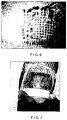
- FIG. 5 The exemplary dressing material as shown in FIG. 5 has been stretched as described herein to separate the micrografts and expand the distance between adjacent micrografts.
- a piece of uncut graft tissue is shown to the left of the stretched dressing in FIG. 5 .
- a similar piece of stretched dressing material having micrografts adhered thereto that were formed using the exemplary mesh apparatus shown in FIG. 4A is shown in FIG. 6 .
- the exemplary stretched dressing materials shown in FIGS. 5 and 6 support an array of spatially separated micrografts. As shown in FIG. 5 and described herein, the area of the stretched dressing material containing the separated micrografts can be much larger than the total area of the original uncut graft tissue.
- Suction blisters may be preferred for preparing recipient sites because they can produce less damage in the underlying tissue than other techniques such as abrading.
- This exemplary micrografting method can facilitate a repigmentation of an area of skin that can be much larger than the area of graft tissue removed from the donor site, e.g., 25x larger or more.
- Other exemplary degrees of expansion can be used by varying the amount of stretching of the dressing material. However, the amount of stretching is preferably small enough to produce a uniform appearance of the treated area after healing has occurred.
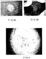
- a further exemplary mesh apparatus can then placed over the graft tissue, as shown in FIG. 8A .
- the exemplary mesh provided in this further mesh apparatus mesh can be thinner than the thickness of the graft tissue.
- a sheet of material used to form the mesh can be less than about 60 microns thick, or less than about 50 microns in thickness.
- Such dimension can facilitate a portion of the graft tissue to protrude above an upper surface of the mesh when the further mesh apparatus is pressed into the graft tissue.
- This exemplary configuration can facilitate formation of portions of tissue that may be used in an autografting procedure as described in more detail below.
- Exemplary micrografts suitable for use with this method can also be formed by mechanical cutting of the epidermal graft tissue into micrografts having a size can be, e.g., between about 100 microns and about 600 microns in size.
- a device that includes a plurality of closely-spaced blades, such as that shown in FIG. 3A may be used as described herein.
- the exemplary mesh apparatus shown in FIG. 4A can be used to cut the graft tissue into individual micrografts. In these mechanical techniques, the stratum corneum of the graft tissue may be placed against the slide or other supporting surface.
- the cutting apparatus can then be pressed onto the upper portion of the graft tissue with sufficient force or pressure to produce cuts that pass substantially through the graft tissue, thereby forming individual micrografts having a size that can be less than about 400 microns.
- These micrografts can then be suspended in a solution that can preferably be sterile and injectable.
- a solution containing a small amount of glycerine e.g., in a concentration of less than about 10%
- the solution can also include electrolytes (e.g., a saline solution) to help maintain viability of the micrograft tissue suspended therein.
- a suction blister can be formed in the depigmented area to be treated.
- a plurality of suction blisters can be formed on the area to be treated, which may allow a larger area to be treated.
- Such exemplary blisters can be formed individually or as an interconnected network of blisters.
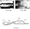
- a plurality of elongated blisters such as those shown in FIG. 10A can be formed on the depigmented area to be treated.
- a plurality of intersecting elongated blisters may be formed, as shown in FIG. 10B .
- the square regions shown in FIG. 10B represent exemplary areas of undisturbed (unblistered or unraised) skin, whereas the network of substantially perpendicular intersecting lines represent raised portions of the epidermis formed by suction blisters.
- a needle 1100 (e.g., a 25G needle or the like) attached to a small syringe 1110 (e.g., a 1 cc syringe) can be inserted into the blister cavity 1120.
- the needle 1100 can be directed such that the needle tip enters the blister cavity 1120 through a lower surface 1130 and does not pierce the raised tissue 1140 covering the blister, as shown in FIG. 11 .
- the micrograft-containing suspension in the syringe 1110 can then be injected into the blister cavity 1120, and the needle 1110 subsequently removed.
- the needle 1100 and an empty syringe 1110 can also be used to optionally drain the blister of fluid.
- the syringe 1110 can then be detached from the needle 1100, and a further syringe 1110 containing the solution with micrografts suspended therein can then be attached to the needle 1100, and the suspension injected into the drained blister.
- the exemplary micrografts within the blister can then settle and attach to the tissue at the lower surface 1130 of the blister.
- the micrografts can contain healthy melanocytes and keratinocytes that can grow over the area being treated to promote healing and/or repigmentation of the skin tissue.
- Some cells provided in the portions of tissue prepared as described herein can undergo a de-differentiation process when transplanted, possibly due to cell signaling mechanisms. Such cells may then proliferate and subsequently differentiate into melanocytes when transplanted to recipient sites (e.g., within suction blisters or a wound dressing).
- the solution or dressing containing the portions of tissue can also include further additives known in the art that promote these effects (such as cell proliferation or differentiation) and can include the additives in a timed fashion to promote the different phases of proliferation, differentiation, etc.
- the suspension containing the micrografts can be more easily retained within the blister cavity 1120.
- the intact raised tissue 1140 can also provide protection for the underlying skin to facilitate healing and reduce the risk of infection.
- the exemplary patterns of blisters shown in FIGS. 10A and 10B include unraised portions of skin between the blisters.
- a small width of these unraised portions can be less than about 4 mm, or preferably less than about 2 mm, to facilitate a migration of melanocytes from beneath the raised blisters to the adjacent unraised portions. Accordingly, these exemplary unraised portions can be sufficiently small to result in an overall uniform pigmented appearance after the blisters heal.
- a further pattern of blisters can optionally be formed over the same region of skin being treated, preferably after the previous blisters have healed. These additional blisters can be formed over areas of the region that were previously unraised/unblistered when the previous blisters were formed. These further blisters can then be drained and injected with a suspension of micrografts as described above, and allowed to heal. This exemplary procedure can be repeated until the desired degree of repigmentation and uniformity is achieved in the area being treated.
- Patterns of intersecting blisters such as that shown in FIG. 10B , may be formed to facilitate distribution of the solution containing melanocytes throughout the 'network' of blisters using a single injection, such as that shown in FIG. 11 (or a small number of such injections provided at various locations within the blister network).
- the blisters can be gently massaged or palpated after injection of the solution containing the melanocytes to facilitate spreading of the melanocytes through the network of blisters.
- Other patterns of intersecting blisters that may be used include, e.g., triangular or hexagonal patterns, which can be formed as a plurality of elongated raised blisters that intersect at various angles.
- the exemplary method described above can facilitate repair and/or repigmentation of skin tissue beneath blisters, while avoiding formation of open wounds on the area being treated. Further, the treated area can be many times larger than the size of the graft tissue removed from a donor site. Thus, larger areas of skin can be repaired or repigmented using a particular amount of graft tissue removed at donor sites.
- the methods described herein can be applied to other tissues besides skin tissue, including other epithelial tissues such as lower GI tract for ulcerated tissue.
- grafts can be formed for various tissues that provide relatively little damage and rapid healing at a donor site while creating graft tissue suitable for repairing larger areas at recipient sites.
- exemplary embodiments of the present disclosure can provide an exemplary stretching apparatus 1200 that may be used to controllably stretch dressing material 1250 (e.g., TegadermTm dressing) having micrografts adhered thereto, as shown in FIGS. 12A-12D .
- dressing material 1250 e.g., TegadermTm dressing
- the exemplary apparatus 1200 can be used to controllably increase the distances between the attached micrografts as described herein, for repairing or repigmenting larger areas of skin.
- the exemplary stretching apparatus 1200 shown in FIG. 12A can include a housing 1210 having a closed end 1220 and an open end 1230.
- the housing 1210 may be substantially cylindrical, or other shapes may be used.
- the size and shape of the shell 1210 can be selected to provide an open end 1230 that can be of substantially similar size as, or larger than, the size of the dressing material 1250 (e.g., having micrografts adhered to) that is to be stretched.
- the housing 1210 and closed end 1220 can be provided together as a continuous structure that surrounds an interior volume and defines the opening 1230.
- the dressing material 1250 can be placed over the open end 1230 of the stretching apparatus 1200, with the micrografts adhered to the outer surface of the dressing material 1250 (e.g., the side external to the interior of the stretching apparatus 1200).
- the dressing material 1250 can then be secured over the opening 1230, e.g., by using an 0-ring 1260, an elastic band, or the like.
- a pressure source 1270 can be provided in communication with the interior volume of the shell 1210, optionally through a valve arrangement 1275.
- the pressure source 1270 and the valve arrangement 1275 for example, can be configured to provide and/or maintain a predetermined pressure within the interior volume of the exemplary stretching apparatus 1200.
- the pressure source 1270 and the valve arrangement 1275 can be configured to controllably increase the pressure in the interior volume of the stretching apparatus 1200 until a particular amount of stretching of the dressing material 1250 has occurred.
- the pressure source 1270 can include, for example, an air pump (e.g., an electric pump or a hand pump).
- the pressure source 1270 can be a tube that facilitates air to be blown into the interior volume of the stretching apparatus 1200 orally.
- the pressure source 1270 can include a canister enclosing a volume of compressed gas that may be controllably released into the interior volume of the stretching apparatus 1200 using, e.g., the valve arrangement 1275.
- Pressure can be increased in the interior volume of the shell 1210, e.g., by forcing a gas or other fluid into the interior volume. This increased pressure can lead to an expansion of the dressing material 1250 over the open end 1230 of the stretching apparatus 1200.
- the pressure source 1270 can include a control arrangement configured to control the amount of stretching of the dressing material 1250. For example, a simple on/off switch may be used, with the amount of stretching manually controlled using the switch based on visual observation.
- the control arrangement may include a pressure display, and/or a pressure sensor connected to the valve arrangement 1275, such that a predetermined pressure can be provided within the interior volume of the shell 1210.
- the exemplary stretching apparatus 1200 shown in FIG. 12A thus can facilitate a controlled amount of stretching of the dressing material 1250.
- the dressing material 1250 can be stretched substantially uniformly in different directions using the stretching apparatus 1200.
- Such stretching may not be uniform or omnidirectional if the dressing material is stretched using conventional techniques, e.g., if the edges of the dressing material 1250 are pulled in different directions by hand or by using a clamping device.
- the exemplary stretching apparatus 1200 can further include a substrate 1280 affixed to a rod 1285.
- the substrate 1280 can be located within the interior volume of the stretching apparatus 1200.
- the rod 1285 may pass through an opening in the closed end 1220 of the apparatus 1200, or otherwise movably connected to the housing 1210, such that the position of the substrate 1280 can be varied relative to the open end 1230 of the housing 1210 by moving a proximal end of the rod 1285 that protrudes beyond a lower surface of the closed end 1220.
- a seal can be provided between the closed end 1220 and the rod 1285 that passes therethrough, where the seal is configured to maintaining an elevated pressure within the apparatus 1200, e.g., the seal may not allow a significant amount of gas to leak out through the opening in the closed end 1220, even when the rod 1285 is moved.
- the interior volume of the exemplary stretching apparatus 1200 can be pressurized using the pressure source 1270 and/or the valve arrangement 1275, such that the dressing material 1250 having micrografts adhered thereto is stretched as shown in FIG. 12B .
- the substrate 1280 can be moved towards the stretched dressing material 1250 such that it contacts at least a portion of the dressing material 1250, as shown in FIG. 12C .
- Pressure within the interior of the apparatus 1200 can then optionally be released or reduced, e.g., using the valve arrangement 1275.
- the dressing material 1250 can then be trimmed or cut around the perimeter of the substrate 1280. This exemplary procedure can provide a portion of dressing material 1250 that is partially adhered to the substrate 1280 in a stretched or expanded state, as shown in FIG. 12D .
- a portion of the dressing material 1250 may be left protruding beyond the edges of the substrate 1280 to facilitate positioning and application of the expanded dressing material 1250 to an area of prepared skin to be treated as described herein.
- the rod 1285 can also be used as a handle to position the portion of dressing material 1250 over the area to be treated.
- exemplary embodiments of the present disclosure can provide a suction apparatus 1300 as shown in FIG. 13A , which can be used to form suction blisters in various configurations such as the exemplary blister network shown in FIG. 10B .
- a general suction blister device is described, e.g., in U.S. Patent No. 6,071,247 .
- the exemplary suction apparatus 1300 can include a vacuum source 1310.
- the vacuum source 1310 can be a handheld pump which includes a pump body 1312 and a pair of spring-loaded handles 1316 that can be squeezed together one or more times to produce suction.
- the vacuum source 1310 can include, e.g., an electric pump or a vessel containing a heated volume of gas that is allowed to cool and contract.
- the vacuum source 1310 can be provided in connection with a plate 1340 via tube 1330.
- One or more channels 1342 can be provided along the lower surface of the plate 1340. For example, a continuous network of such channels 1342 as viewed from the lower surface of the plate 1340 is shown in FIG. 13B .
- One or more conduits 1344 can be provided to form a passageway between the channel 1342 and an outer surface of the plate 1340. For example, at least one conduit 1344 can be provided for each separate channel 1342 in the block 1340. Each separate channel 1342 can then be used to form a separate suction blister.
- a pressure gauge 1320 can optionally be connected to the vacuum source 1310 to indicate the current pressure present between the tissue surface and the channel 1342.
- the exemplary suction apparatus 1300 can be operated by placing the plate 1340 over the region of skin to be treated.
- a gel or other material can be provided on the lower surface of the plate 1340 to improve a seal between the plate 1340 and the skin surface.
- the region of skin can optionally be heated before the plate 1340 is applied, e.g., to a temperature up to about 45 °C, or preferably between about 39 C-41C.
- the heating can be performed using a conventional technique, such as contacting a warm object to the skin or exposing the skin to heated water or another fluid.
- Non-contact heating techniques and devices e.g., heat lamps or infrared radiators, may also be used. Such heating can optionally be provided while the blister is being formed.
- the vacuum source 1310 can then be activated to produce a partial vacuum (e.g., a lower pressure) in the channels 1342.
- a partial vacuum e.g., a lower pressure
- An appropriate low pressure can be maintained in the channels 1342 for a sufficient time to form suction blisters in the underlying skin, having the same pattern as the channels 1342.
- the time and pressure required to form suction blisters can be determined in accordance with conventional suction blister techniques. The time preferred to form such suction blisters can be reduced if the skin is preheated before application of the exemplary suction apparatus 1300.
- the distance between adjacent channels may be less than about 4 mm, or preferably less than about 2 mm, to allow migration of melanocytes from beneath the formed blisters to the adjacent unraised portions, as described herein.
- a width of each channel can be less than about 10 mm wide, or less than about 5 mm wide. Such exemplary widths can form blisters that are large enough to provide a sufficient amount of blister area to be grafted to, while avoiding excessively large blisters that may take a long time to heal.
- exemplary embodiments of the present disclosure can provide an autografting method and apparatus in which a plurality of small spaced-apart grafts are formed at predetermined locations at a donor site and applied to a treatment site.
- a plurality of small blisters e.g., suction blisters or other raised portions of skin tissue
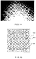
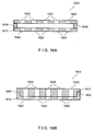
- Such blisters can be formed, e.g., using an exemplary suction blister apparatus 1500 that can include a plate or sheet 1510 having a plurality of holes 1520 there through, e.g., as shown in FIG. 15 .
- a width or diameter of each blister can be between about 0.5 mm and about 2.5 mm in diameter, which can provide graft tissue samples that are large enough to repair a large area of skin at a recipient site, while being small enough to facilitate healing after the graft tissue samples are removed from the donor site.
- larger or smaller blister sizes can also be used.
- the holes 1520 can be provided in any one of a variety of shapes. Holes that are substantially circular or ellipsoidal, e.g., having convex curved shapes, can be preferable to produce raised blisters having well-defined edges.
- each of the plates 1610, 1615 can include a plurality of holes 1620 therethrough, where the pattern of holes 1620 can be substantially the same as or similar to that used to form the blisters.
- the lower plate 1615 can be omitted, and the spacers 1630 can be configured to position the upper plate 1610 having the pattern of holes 1620 at a small distance away from the surface of the skin when the apparatus 1600 is placed over the formed blisters.
- a vacuum source can be provided over the apparatus 1600 after it is placed on the skin, to form a plurality of blisters through the holes 1620.
- a plurality of blisters can be formed on a recipient site using the same technique described above for the donor site.
- the pattern or spatial arrangement of blisters can be substantially the same at both the donor and recipient sites.
- each set of blisters can be formed using the same apparatus 1500 shown in FIG. 15 or a similar apparatus or article of manufacture.
- the blisters at the recipient site can be severed and discarded, or alternatively they can be affixed to a second piece of dressing material as described above with respect to the small blisters formed at the donor site.
- the dressing material having the pattern of small grafts from the donor site adhered thereto can then be placed over the recipient site, such that the grafts are substantially aligned with the exposed areas where blisters were removed.
- the dressing can be left in place for a sufficient time to facilitate or allow the grafts to attach to the surrounding tissue (e.g., several days up to a few weeks), and the dressing material can then be removed.
- this second piece of dressing material can be affixed over the donor site, such that the blisters removed from the recipient site substantially align with the exposed areas from the donor site where blisters were severed.
- This second dressing material can also be left in place until the blister pieces have sufficiently become attached to the surrounding tissue at the donor site.
- a plurality of separate, small grafts can be formed and removed from a donor site and positioned over corresponding exposed areas of skin at a recipient site.
- the small pieces of tissue removed from the recipient site can also be positioned over matching exposed areas of skin at the donor site.
- the recipient site can be prepared, for example, by removing at least a portion of the epidermis at the recipient site. Such preparation can be performed, e.g., using conventional dermabrading techniques.
- the dressing material having the small grafts from the donor site adhered thereto can then be placed over the recipient site, such that at least a portion of the grafts are aligned with areas of the recipient site where some or all of the epidermal tissue was removed.
- the dressing can be left in place for a sufficient time to facilitate or allow the grafts to attach to the surrounding tissue (e.g., several days up to a few weeks), as described above.
- Average distances between adjacent small grafts on the dressing material can be selected based on migration of melanocytes and/or keratinocytes, as described above.
- an average distances between nearest edges of adjacent small grafts can be less than about 4 mm, or less than about 2 mm, to facilitate migration of melanocytes between the small grafts. This average distance can be larger if keratinocytes migration is relevant to the tissue being treated, e.g., based on the greater typical migration distances of keratinocytes as compared with melanocytes.
- An exemplary grafting procedure was performed in accordance with exemplary embodiments of the present disclosure, as described below in detail.
- the exemplary procedure was performed to provide repigmentation of a wrist area of a subject exhibiting depigmentation associated with vitiligo.
- the blisters were formed by heating the donor site to a temperature of about 41 °C and using a suction pressure of about 15 inches (1/2 atm.). Each piece of tissue obtained from a blister was about 8 mm in diameter.
- the donor site from which the five pieces of tissue were removed is shown in FIG. 17A , about six weeks after the blisters were formed. A small amount of hyperpigmentation (darkening) is visible where the epidermal tissue was removed. No dermal involvement or scarring was observed, and the mild hyperpigmentation may disappear within about 3-6 months.
- Each of these pieces of epidermal graft tissue was then used to form a plurality of micrografts by pressing two stacked stainless steel meshes onto the outer (skin surface or stratum corneum) side of the graft using a mechanical press, as described herein.
- Each mesh was about 90 microns thick (corresponding to a stack having a total thickness of about 180 microns), with a width of each mesh line of about 100 microns.
- the holes in the mesh were about 400 microns wide.
- a plurality of micrografts was formed from each piece of donor tissue, with each micrograft being about 400 microns wide.
- the micrografts were only partially separated from one another by the mesh apparatus, connected by small uncut portions of tissue, such that each piece of donor tissue could be handled as a single unit after forming the plurality of micrografts therefrom.
- the five epidermal pieces of graft tissue were then placed on the sticky side of a piece of TegadermTm dressing (3M) as described herein, adjacent to one another, with the outer skin surface (stratum comeum) adhered to the TegadermTm dressing.
- TegadermTm dressing 3M
- This orientation facilitates direct contact between the keratinocytes and the melanocytes present in the graft tissue and the prepared surface of the recipient site, when the TegadermTm dressing is placed over the recipient site.
- the TegadermTm dressing with the graft tissue adhered thereto was then affixed to the exemplary expansion device shown in FIG. 12A using an 0-ring.
- a pump was used to increase the pressure within the expansion device and expand the TegadermTm dressing like a balloon, so as to stretch the dressing uniformly. This procedure resulted in a separation of adjacent micrografts as described herein.
- the individual micrografts did not appear to be stretched individually because of their small size and because the dead stratum corneum layer of each micrograft is adhered to the dressing, which does not directly contact live cells of the epidermis, allowing each micrograft to maintain its integrity.
- the TegadermTm dressing was expanded such that a distance of about 2 mm between adjacent micrografts was formed without tearing of the stretched dressing. This corresponded to an area of dressing containing micrografts that was about 2.5 to 3 times the size of the donor site.
- a plastic ring was then adhered to the dressing just beyond the outer perimeter of the array of micrografts adhered to the dressing, to hold the dressing in a stretched configuration, and the outer portions of the dressing were then cut off around the ring.
- Another piece of unstretched TegadermTm dressing was then adhered to the non-sticky side of the stretched dressing to provide further strength and stability.
- the recipient site was dermabraded using a conventional procedure, and kept moist.
- the unstretched TegadermTm dressing provided the outer surface of the dressing, away from the skin tissue.
- This dressing arrangement, including micrografts adhered thereto, is shown applied to the recipient site on the left wrist of the subject in FIG. 17B .
- the subject was then sent home with this dressing material held in place.
- the dressing on the recipient site was changed after seven days. No antibiotics or pain killers were prescribed and they did not appear to be necessary. When the dressing was changed (seven days after the micrografts were applied to the recipient site), no repigmentation was observed. The recipient site appeared clean, with no evidence of infection or any other complication.
- FIGS. 17C and 17D show the recipient site before and six weeks after application of the micrografts as described herein. The height of the circled treatment area in these figures is about 3 cm. Much of the depigmented areas shown in FIG. 17C have become pigmented after six weeks, as shown in FIG. 17D , through attachment and growth of the applied micrografts.
Landscapes
- Health & Medical Sciences (AREA)
- Life Sciences & Earth Sciences (AREA)
- Transplantation (AREA)
- Veterinary Medicine (AREA)
- Engineering & Computer Science (AREA)
- Animal Behavior & Ethology (AREA)
- Public Health (AREA)
- General Health & Medical Sciences (AREA)
- Surgery (AREA)
- Biomedical Technology (AREA)
- Heart & Thoracic Surgery (AREA)
- Nuclear Medicine, Radiotherapy & Molecular Imaging (AREA)
- Dermatology (AREA)
- Medical Informatics (AREA)
- Molecular Biology (AREA)
- Vascular Medicine (AREA)
- Oral & Maxillofacial Surgery (AREA)
- Cardiology (AREA)
- Plastic & Reconstructive Surgery (AREA)
- General Chemical & Material Sciences (AREA)
- Chemical & Material Sciences (AREA)
- Bioinformatics & Cheminformatics (AREA)
- Chemical Kinetics & Catalysis (AREA)
- Pharmacology & Pharmacy (AREA)
- Medicinal Chemistry (AREA)
- Organic Chemistry (AREA)
- Prostheses (AREA)
- Materials For Medical Uses (AREA)
- Surgical Instruments (AREA)
- Medicines Containing Material From Animals Or Micro-Organisms (AREA)
- Micro-Organisms Or Cultivation Processes Thereof (AREA)
Applications Claiming Priority (4)
| Application Number | Priority Date | Filing Date | Title |
|---|---|---|---|
| US9979908P | 2008-09-24 | 2008-09-24 | |
| US15384609P | 2009-02-19 | 2009-02-19 | |
| PCT/US2009/058194 WO2010036788A2 (en) | 2008-09-24 | 2009-09-24 | Method and apparatus for grafting of skin tissue |
| EP09816842.0A EP2337507B1 (de) | 2008-09-24 | 2009-09-24 | Verfahren und vorrichtung zum einsetzen von hautgewebe |
Related Parent Applications (2)
| Application Number | Title | Priority Date | Filing Date |
|---|---|---|---|
| EP09816842.0A Division-Into EP2337507B1 (de) | 2008-09-24 | 2009-09-24 | Verfahren und vorrichtung zum einsetzen von hautgewebe |
| EP09816842.0A Division EP2337507B1 (de) | 2008-09-24 | 2009-09-24 | Verfahren und vorrichtung zum einsetzen von hautgewebe |
Publications (3)
| Publication Number | Publication Date |
|---|---|
| EP3037051A2 true EP3037051A2 (de) | 2016-06-29 |
| EP3037051A3 EP3037051A3 (de) | 2016-10-12 |
| EP3037051B1 EP3037051B1 (de) | 2019-08-28 |
Family
ID=42060385
Family Applications (2)
| Application Number | Title | Priority Date | Filing Date |
|---|---|---|---|
| EP16156038.8A Active EP3037051B1 (de) | 2008-09-24 | 2009-09-24 | Vorrichtung zum einsetzen von hautgewebe |
| EP09816842.0A Active EP2337507B1 (de) | 2008-09-24 | 2009-09-24 | Verfahren und vorrichtung zum einsetzen von hautgewebe |
Family Applications After (1)
| Application Number | Title | Priority Date | Filing Date |
|---|---|---|---|
| EP09816842.0A Active EP2337507B1 (de) | 2008-09-24 | 2009-09-24 | Verfahren und vorrichtung zum einsetzen von hautgewebe |
Country Status (7)
| Country | Link |
|---|---|
| US (3) | US9451979B2 (de) |
| EP (2) | EP3037051B1 (de) |
| JP (2) | JP5770632B2 (de) |
| KR (1) | KR101642821B1 (de) |
| BR (1) | BRPI0919260B8 (de) |
| CA (1) | CA2738476C (de) |
| WO (1) | WO2010036788A2 (de) |
Families Citing this family (53)
| Publication number | Priority date | Publication date | Assignee | Title |
|---|---|---|---|---|
| US8501396B2 (en) | 2001-11-05 | 2013-08-06 | Medgenics Medical Israel Ltd. | Dermal micro-organs, methods and apparatuses for producing and using the same |
| US7468242B2 (en) | 2001-11-05 | 2008-12-23 | Medgenics, Inc. | Dermal micro organs, methods and apparatuses for producing and using the same |
| HRP20120673T1 (hr) | 2003-05-01 | 2012-10-31 | Medgenics, Inc. | Uporaba dermalnih mikroorgana |
| BRPI0919260B8 (pt) | 2008-09-24 | 2021-06-22 | Massachusetts Inst Technology | equipamentos para formar pluralidade de tecidos de enxerto, para expandir membrana, para formar pluralidade de microenxertos a partir de pelo menos parte de tecido de enxerto e para produzir bolhas de sucção e método para afetar região de pele |
| WO2011075676A2 (en) | 2009-12-18 | 2011-06-23 | Knowlton Edward W | A skin treatment and drug delivery device |
| US9173674B2 (en) * | 2010-08-06 | 2015-11-03 | MoMelan Technologies, Inc. | Devices for harvesting a skin graft |
| US8617181B2 (en) * | 2010-08-06 | 2013-12-31 | MoMelan Technologies, Inc. | Methods for preparing a skin graft |
| US8926631B2 (en) | 2010-08-06 | 2015-01-06 | MoMelan Technologies, Inc. | Methods for preparing a skin graft without culturing or use of biologics |
| US9597111B2 (en) | 2010-08-06 | 2017-03-21 | Kci Licensing, Inc. | Methods for applying a skin graft |
| US9610093B2 (en) * | 2010-08-06 | 2017-04-04 | Kci Licensing, Inc. | Microblister skin grafting |
| US8978234B2 (en) * | 2011-12-07 | 2015-03-17 | MoMelan Technologies, Inc. | Methods of manufacturing devices for generating skin grafts |
| US8562626B2 (en) * | 2010-08-06 | 2013-10-22 | MoMelan Technologies, Inc. | Devices for harvesting a skin graft |
| US11109887B2 (en) | 2013-12-06 | 2021-09-07 | Srgi Holdings, Llc | Pixel array medical systems, devices and methods |
| US11000310B2 (en) | 2010-12-17 | 2021-05-11 | Srgi Holdings, Llc | Pixel array medical systems, devices and methods |
| US10695546B2 (en) | 2010-12-17 | 2020-06-30 | Srgi Holdings, Llc | Systems, devices and methods for fractional resection, fractional skin grafting, fractional scar reduction and fractional tattoo removal |
| US10080581B2 (en) | 2010-12-17 | 2018-09-25 | Srgi Holding Llc | Pixel array medical devices and methods |
| US10736653B2 (en) | 2013-12-06 | 2020-08-11 | Srgi Holdings, Llc | Pixel array medical systems, devices and methods |
| US11278309B2 (en) | 2010-12-17 | 2022-03-22 | Srgi Holdings, Llc | Pixel array medical systems, devices and methods |
| US11103275B2 (en) | 2010-12-17 | 2021-08-31 | Srgi Holdings, Llc | Pixel array medical systems, devices and methods |
| US10321948B2 (en) | 2010-12-17 | 2019-06-18 | Srgi Holdings, Llc | Pixel array medical devices and methods |
| US10967162B2 (en) | 2010-12-17 | 2021-04-06 | Srgi Holdings, Llc | Systems, devices and methods for fractional resection, fractional skin grafting, fractional scar reduction and fractional tattoo removal |
| US10702684B2 (en) | 2010-12-17 | 2020-07-07 | Srgi Holdings, Llc | Systems, devices and methods for fractional resection, fractional skin grafting, fractional scar reduction and fractional tattoo removal |
| US10335190B2 (en) | 2013-12-06 | 2019-07-02 | Srgi Holdings, Llc | Pixel array medical systems, devices and methods |
| US20120197267A1 (en) * | 2011-01-27 | 2012-08-02 | MoMelan Technologies, Inc. | Devices for generating and transferring micrografts and methods of use thereof |
| JP6367220B2 (ja) * | 2012-12-06 | 2018-08-01 | エスアールジーアイ ホールディングス エルエルシーSrgi Holdings Llc | ピクセルアレイ医療デバイス及び方法 |
| CN105636532B (zh) * | 2013-03-14 | 2019-06-21 | 凯希特许有限公司 | 用于采集皮肤移植片的吸收性基底 |
| JP6436157B2 (ja) | 2013-03-15 | 2018-12-12 | ケーシーアイ ライセンシング インコーポレイテッド | 微小疱皮膚移植 |
| KR102382212B1 (ko) * | 2013-10-02 | 2022-04-04 | 에스알쥐아이 홀딩스 엘엘씨 | 픽셀 어레이 의료용 장치 및 방법 |
| ES2827049T3 (es) | 2013-10-02 | 2021-05-19 | Srgi Holdings Llc | Dispositivos médicos de conjunto de píxeles |
| US11937846B2 (en) | 2013-12-06 | 2024-03-26 | Srgi Holdings Llc | Pixel array medical systems, devices and methods |
| US11229452B2 (en) | 2013-12-06 | 2022-01-25 | Srgi Holdings, Llc | Pixel array medical systems, devices and methods |
| EP3243453B1 (de) * | 2013-12-31 | 2019-10-09 | KCI Licensing, Inc. | Hautimplantatentnahmevorrichtung |
| US10463392B2 (en) | 2013-12-31 | 2019-11-05 | Kci Licensing, Inc. | Fluid-assisted skin graft harvesting |
| EP3579767B1 (de) | 2014-10-02 | 2025-10-08 | SRGI Holdings, LLC | Medizinische systeme und vorrichtungen mit pixelanordnung |
| WO2016127091A1 (en) | 2015-02-05 | 2016-08-11 | Srgi Holdings, Llc | Pixel array medical systems, devices and methods |
| EP3804774A1 (de) | 2015-04-09 | 2021-04-14 | 3M Innovative Properties Co. | System zur entnahme von hauttransplantaten |
| US11751904B2 (en) | 2015-08-31 | 2023-09-12 | Srgi Holdings, Llc | Pixel array medical systems, devices and methods |
| US11490952B2 (en) | 2015-08-31 | 2022-11-08 | Srgi Holdings, Llc | Pixel array medical devices and methods |
| US11980389B2 (en) | 2015-08-31 | 2024-05-14 | Srgi Holdings Llc | Handed spiral slotted scalpet array |
| EP3370630B1 (de) | 2015-11-03 | 2021-06-16 | 3M Innovative Properties Company | Vorrichtung zur herstellung einer epidermalen transplantatfolie |
| US11564706B2 (en) | 2019-10-28 | 2023-01-31 | Srgi Holdings, Llc | Pixel array medical systems, devices and methods |
| EP3531939B1 (de) * | 2016-10-28 | 2022-12-07 | The General Hospital Corporation | Systeme zum zusammenfügen von gewebetransplantaten |
| KR102051223B1 (ko) | 2017-09-05 | 2019-12-03 | 이준석 | 생체조직 미세화 장치 |
| WO2019050251A1 (ko) * | 2017-09-05 | 2019-03-14 | 이준석 | 생체조직 미세화 장치 |
| WO2019108738A1 (en) * | 2017-11-29 | 2019-06-06 | Kci Licensing, Inc. | Nanomodified transfer drape for epidermal grafting |
| US20210244432A1 (en) * | 2018-06-11 | 2021-08-12 | The General Hospital Corporation | Skin construct transfer system and method |
| CN108703778B (zh) * | 2018-06-15 | 2024-04-05 | 魏子人 | 一种医用带线皮钉挂钩和医用带线皮钉挂钩结构 |
| US11344328B2 (en) | 2019-09-19 | 2022-05-31 | Tara Medical Devices, LLC | Devices, systems, and methods for epidermal tissue harvesting |
| WO2022126005A1 (en) * | 2020-12-11 | 2022-06-16 | 3D Systems, Inc. | Carrier matrix for facilitating transfer of skin cores from donor site to wound site |
| EP4312800A4 (de) * | 2021-03-22 | 2025-02-19 | The General Hospital Corporation | Injizierbarer füllstoff aus autologer dermis ohne spendervernarbung |
| WO2023209039A2 (en) | 2022-04-27 | 2023-11-02 | Gerlach, Jörg C. | Tissue structure isolation using a micro-cutting device and uses of resulting micro-cubes of tissue |
| KR102683102B1 (ko) * | 2023-11-30 | 2024-07-10 | 디에스메카 주식회사 | 비수술 일체형 생체 시료 분리 및 정량 주입 시스템 |
| CN118022062B (zh) * | 2024-01-31 | 2024-10-18 | 中国人民解放军总医院第四医学中心 | 一种混合皮片meek植皮材料及制备方法 |
Citations (1)
| Publication number | Priority date | Publication date | Assignee | Title |
|---|---|---|---|---|
| US6071247A (en) | 1996-07-21 | 2000-06-06 | Kennedy; William R. | Skin blister biopsy apparatus and method |
Family Cites Families (36)
| Publication number | Priority date | Publication date | Assignee | Title |
|---|---|---|---|---|
| US2590299A (en) * | 1948-09-20 | 1952-03-25 | Douglas Beverly | Apparatus for removing human skin for grafting purposes |
| US3782387A (en) * | 1972-02-29 | 1974-01-01 | R Falabella | Apparatus and methods for obtaining and making skin grafts |
| US5921980A (en) * | 1997-12-03 | 1999-07-13 | University Of Kentucky Research Foundation | Laser skin graft harvesting apparatus and related method |
| AU753094B2 (en) * | 1998-06-22 | 2002-10-10 | Astrazeneca Ab | Device for emptying cavities containing powder by means of suction |
| SE9904706D0 (sv) | 1999-12-21 | 1999-12-21 | Astra Ab | An inhalation device |
| FR2803918B1 (fr) * | 2000-01-17 | 2003-05-16 | Commissariat Energie Atomique | Dispositif de balayage d'un foyer de faisceau de laser |
| US6241658B1 (en) * | 2000-07-12 | 2001-06-05 | Harriet T. Goodrich | Suction retractor |
| US7651507B2 (en) * | 2003-03-03 | 2010-01-26 | Kci Licensing, Inc. | Tissue processing system |
| US7513902B2 (en) * | 2001-10-01 | 2009-04-07 | The Cleveland Clinic Foundation | Skin lesion exciser and skin-closure device therefor |
| JP4447916B2 (ja) * | 2001-11-05 | 2010-04-07 | メドジニックス・インコーポレイテッド | 微小器官処理システム及びそれを用いた微小器官の製造方法 |
| CA2536394A1 (en) * | 2003-09-03 | 2005-07-28 | Rubicor Medical, Inc. | Short term post surgical cavity treatment devices and methods |
| US8357103B2 (en) * | 2003-10-14 | 2013-01-22 | Suros Surgical Systems, Inc. | Vacuum assisted biopsy needle set |
| US7799042B2 (en) * | 2004-05-13 | 2010-09-21 | The Cleveland Clinic Foundation | Skin lesion exciser and skin-closure device therefor |
| US8932233B2 (en) * | 2004-05-21 | 2015-01-13 | Devicor Medical Products, Inc. | MRI biopsy device |
| US7455681B2 (en) * | 2004-09-13 | 2008-11-25 | Wound Care Technologies, Llc | Wound closure product |
| US20080051822A1 (en) * | 2005-01-18 | 2008-02-28 | Widgerow Alan D | Methods and apparatus for use in medical treatment |
| WO2007034438A2 (en) * | 2005-09-26 | 2007-03-29 | Koninklijke Philips Electronics N.V. | Substance sampling and/or substance delivery via skin |
| US8568333B2 (en) * | 2006-05-01 | 2013-10-29 | Devicor Medical Products, Inc. | Grid and rotatable cube guide localization fixture for biopsy device |
| BRPI0919260B8 (pt) | 2008-09-24 | 2021-06-22 | Massachusetts Inst Technology | equipamentos para formar pluralidade de tecidos de enxerto, para expandir membrana, para formar pluralidade de microenxertos a partir de pelo menos parte de tecido de enxerto e para produzir bolhas de sucção e método para afetar região de pele |
| US9597111B2 (en) | 2010-08-06 | 2017-03-21 | Kci Licensing, Inc. | Methods for applying a skin graft |
| US8617181B2 (en) | 2010-08-06 | 2013-12-31 | MoMelan Technologies, Inc. | Methods for preparing a skin graft |
| US8978234B2 (en) | 2011-12-07 | 2015-03-17 | MoMelan Technologies, Inc. | Methods of manufacturing devices for generating skin grafts |
| US8562626B2 (en) | 2010-08-06 | 2013-10-22 | MoMelan Technologies, Inc. | Devices for harvesting a skin graft |
| US9610093B2 (en) | 2010-08-06 | 2017-04-04 | Kci Licensing, Inc. | Microblister skin grafting |
| US9173674B2 (en) | 2010-08-06 | 2015-11-03 | MoMelan Technologies, Inc. | Devices for harvesting a skin graft |
| US8926631B2 (en) | 2010-08-06 | 2015-01-06 | MoMelan Technologies, Inc. | Methods for preparing a skin graft without culturing or use of biologics |
| US20120197267A1 (en) | 2011-01-27 | 2012-08-02 | MoMelan Technologies, Inc. | Devices for generating and transferring micrografts and methods of use thereof |
| USD732665S1 (en) | 2012-07-13 | 2015-06-23 | MoMelan Technologies, Inc. | Dermatological device |
| USD729386S1 (en) | 2012-07-13 | 2015-05-12 | MoMelan Technologies, Inc. | Dermatological system |
| USD706422S1 (en) | 2012-07-13 | 2014-06-03 | Momelan Technologies | Dermatological device |
| CN105636532B (zh) | 2013-03-14 | 2019-06-21 | 凯希特许有限公司 | 用于采集皮肤移植片的吸收性基底 |
| JP6436157B2 (ja) | 2013-03-15 | 2018-12-12 | ケーシーアイ ライセンシング インコーポレイテッド | 微小疱皮膚移植 |
| WO2015103045A1 (en) | 2013-12-31 | 2015-07-09 | Kci Licensing, Inc. | Hydraulically actuated skin graft harvesting |
| US10463392B2 (en) | 2013-12-31 | 2019-11-05 | Kci Licensing, Inc. | Fluid-assisted skin graft harvesting |
| EP3243453B1 (de) | 2013-12-31 | 2019-10-09 | KCI Licensing, Inc. | Hautimplantatentnahmevorrichtung |
| EP3804774A1 (de) | 2015-04-09 | 2021-04-14 | 3M Innovative Properties Co. | System zur entnahme von hauttransplantaten |
-
2009
- 2009-09-24 BR BRPI0919260A patent/BRPI0919260B8/pt active IP Right Grant
- 2009-09-24 US US13/120,799 patent/US9451979B2/en active Active
- 2009-09-24 KR KR1020117009193A patent/KR101642821B1/ko active Active
- 2009-09-24 EP EP16156038.8A patent/EP3037051B1/de active Active
- 2009-09-24 JP JP2011529220A patent/JP5770632B2/ja active Active
- 2009-09-24 WO PCT/US2009/058194 patent/WO2010036788A2/en not_active Ceased
- 2009-09-24 EP EP09816842.0A patent/EP2337507B1/de active Active
- 2009-09-24 CA CA2738476A patent/CA2738476C/en active Active
-
2015
- 2015-01-06 JP JP2015000930A patent/JP5989141B2/ja active Active
-
2016
- 2016-08-31 US US15/253,525 patent/US10278724B2/en active Active
-
2019
- 2019-05-06 US US16/404,316 patent/US11684388B2/en active Active
Patent Citations (1)
| Publication number | Priority date | Publication date | Assignee | Title |
|---|---|---|---|---|
| US6071247A (en) | 1996-07-21 | 2000-06-06 | Kennedy; William R. | Skin blister biopsy apparatus and method |
Non-Patent Citations (4)
| Title |
|---|
| A.R. LAN I ET AL., BURNS, vol. 27, 2001, pages 61 - 66 |
| R.W. KREIS ET AL., BURNS, vol. 20, no. 1, 1994, pages S39 - S42 |
| S.S. AWAD, DERMATOL SURG, vol. 34, no. 9, September 2008 (2008-09-01), pages 1186 - 1193 |
| S.V. MULEKAR ET AL., DERMATOL SURG, vol. 35, no. 1, January 2009 (2009-01-01), pages 66 - 71 |
Also Published As
| Publication number | Publication date |
|---|---|
| JP2012503528A (ja) | 2012-02-09 |
| JP2015109983A (ja) | 2015-06-18 |
| WO2010036788A3 (en) | 2010-06-24 |
| JP5989141B2 (ja) | 2016-09-07 |
| US20110264115A1 (en) | 2011-10-27 |
| CA2738476C (en) | 2017-06-27 |
| US20190254694A1 (en) | 2019-08-22 |
| EP2337507B1 (de) | 2016-04-13 |
| KR20110102874A (ko) | 2011-09-19 |
| EP2337507A4 (de) | 2012-10-31 |
| EP2337507A2 (de) | 2011-06-29 |
| JP5770632B2 (ja) | 2015-08-26 |
| EP3037051A3 (de) | 2016-10-12 |
| US20170128096A1 (en) | 2017-05-11 |
| BRPI0919260A2 (pt) | 2017-05-30 |
| WO2010036788A2 (en) | 2010-04-01 |
| US11684388B2 (en) | 2023-06-27 |
| KR101642821B1 (ko) | 2016-07-26 |
| US9451979B2 (en) | 2016-09-27 |
| BRPI0919260B1 (pt) | 2020-04-07 |
| US20230132373A9 (en) | 2023-04-27 |
| EP3037051B1 (de) | 2019-08-28 |
| US10278724B2 (en) | 2019-05-07 |
| BRPI0919260B8 (pt) | 2021-06-22 |
| CA2738476A1 (en) | 2010-04-01 |
Similar Documents
| Publication | Publication Date | Title |
|---|---|---|
| US11684388B2 (en) | Method and apparatus for grafting of skin tissue | |
| US9517082B2 (en) | Methods for preparing a skin graft without culturing or use of biologics | |
| CA2807411C (en) | Devices for preparing a skin graft | |
| US11083487B2 (en) | Methods for preparing a skin graft | |
| Purschke et al. | Novel methods for generating fractional epidermal micrografts |
Legal Events
| Date | Code | Title | Description |
|---|---|---|---|
| PUAI | Public reference made under article 153(3) epc to a published international application that has entered the european phase |
Free format text: ORIGINAL CODE: 0009012 |
|
| AC | Divisional application: reference to earlier application |
Ref document number: 2337507 Country of ref document: EP Kind code of ref document: P |
|
| AK | Designated contracting states |
Kind code of ref document: A2 Designated state(s): AT BE BG CH CY CZ DE DK EE ES FI FR GB GR HR HU IE IS IT LI LT LU LV MC MK MT NL NO PL PT RO SE SI SK SM TR |
|
| PUAL | Search report despatched |
Free format text: ORIGINAL CODE: 0009013 |
|
| AK | Designated contracting states |
Kind code of ref document: A3 Designated state(s): AT BE BG CH CY CZ DE DK EE ES FI FR GB GR HR HU IE IS IT LI LT LU LV MC MK MT NL NO PL PT RO SE SI SK SM TR |
|
| RIC1 | Information provided on ipc code assigned before grant |
Ipc: A61F 2/10 20060101ALI20160902BHEP Ipc: A61B 17/00 20060101ALI20160902BHEP Ipc: A61B 17/322 20060101AFI20160902BHEP |
|
| STAA | Information on the status of an ep patent application or granted ep patent |
Free format text: STATUS: REQUEST FOR EXAMINATION WAS MADE |
|
| RIN1 | Information on inventor provided before grant (corrected) |
Inventor name: FARINELLI, WILLIAM A. Inventor name: ASRANI, FALGUNI Inventor name: SHAH, AJAY Inventor name: ANDERSON, R. ROX Inventor name: LUI, VINCENT |
|
| 17P | Request for examination filed |
Effective date: 20161129 |
|
| RBV | Designated contracting states (corrected) |
Designated state(s): AT BE BG CH CY CZ DE DK EE ES FI FR GB GR HR HU IE IS IT LI LT LU LV MC MK MT NL NO PL PT RO SE SI SK SM TR |
|
| R17P | Request for examination filed (corrected) |
Effective date: 20161205 |
|
| RBV | Designated contracting states (corrected) |
Designated state(s): AT BE BG CH CY CZ DE DK EE ES FI FR GB GR HR HU IE IS IT LI LT LU LV MC MK MT NL NO PL PT RO SE SI SK SM TR |
|
| STAA | Information on the status of an ep patent application or granted ep patent |
Free format text: STATUS: EXAMINATION IS IN PROGRESS |
|
| 17Q | First examination report despatched |
Effective date: 20180920 |
|
| GRAP | Despatch of communication of intention to grant a patent |
Free format text: ORIGINAL CODE: EPIDOSNIGR1 |
|
| STAA | Information on the status of an ep patent application or granted ep patent |
Free format text: STATUS: GRANT OF PATENT IS INTENDED |
|
| INTG | Intention to grant announced |
Effective date: 20190416 |
|
| GRAS | Grant fee paid |
Free format text: ORIGINAL CODE: EPIDOSNIGR3 |
|
| GRAA | (expected) grant |
Free format text: ORIGINAL CODE: 0009210 |
|
| STAA | Information on the status of an ep patent application or granted ep patent |
Free format text: STATUS: THE PATENT HAS BEEN GRANTED |
|
| AC | Divisional application: reference to earlier application |
Ref document number: 2337507 Country of ref document: EP Kind code of ref document: P |
|
| AK | Designated contracting states |
Kind code of ref document: B1 Designated state(s): AT BE BG CH CY CZ DE DK EE ES FI FR GB GR HR HU IE IS IT LI LT LU LV MC MK MT NL NO PL PT RO SE SI SK SM TR |
|
| REG | Reference to a national code |
Ref country code: GB Ref legal event code: FG4D |
|
| REG | Reference to a national code |
Ref country code: CH Ref legal event code: EP |
|
| REG | Reference to a national code |
Ref country code: AT Ref legal event code: REF Ref document number: 1171415 Country of ref document: AT Kind code of ref document: T Effective date: 20190915 |
|
| REG | Reference to a national code |
Ref country code: IE Ref legal event code: FG4D |
|
| REG | Reference to a national code |
Ref country code: DE Ref legal event code: R096 Ref document number: 602009059666 Country of ref document: DE |
|
| REG | Reference to a national code |
Ref country code: NL Ref legal event code: MP Effective date: 20190828 |
|
| REG | Reference to a national code |
Ref country code: LT Ref legal event code: MG4D |
|
| PG25 | Lapsed in a contracting state [announced via postgrant information from national office to epo] |
Ref country code: FI Free format text: LAPSE BECAUSE OF FAILURE TO SUBMIT A TRANSLATION OF THE DESCRIPTION OR TO PAY THE FEE WITHIN THE PRESCRIBED TIME-LIMIT Effective date: 20190828 Ref country code: PT Free format text: LAPSE BECAUSE OF FAILURE TO SUBMIT A TRANSLATION OF THE DESCRIPTION OR TO PAY THE FEE WITHIN THE PRESCRIBED TIME-LIMIT Effective date: 20191230 Ref country code: NO Free format text: LAPSE BECAUSE OF FAILURE TO SUBMIT A TRANSLATION OF THE DESCRIPTION OR TO PAY THE FEE WITHIN THE PRESCRIBED TIME-LIMIT Effective date: 20191128 Ref country code: NL Free format text: LAPSE BECAUSE OF FAILURE TO SUBMIT A TRANSLATION OF THE DESCRIPTION OR TO PAY THE FEE WITHIN THE PRESCRIBED TIME-LIMIT Effective date: 20190828 Ref country code: HR Free format text: LAPSE BECAUSE OF FAILURE TO SUBMIT A TRANSLATION OF THE DESCRIPTION OR TO PAY THE FEE WITHIN THE PRESCRIBED TIME-LIMIT Effective date: 20190828 Ref country code: LT Free format text: LAPSE BECAUSE OF FAILURE TO SUBMIT A TRANSLATION OF THE DESCRIPTION OR TO PAY THE FEE WITHIN THE PRESCRIBED TIME-LIMIT Effective date: 20190828 Ref country code: SE Free format text: LAPSE BECAUSE OF FAILURE TO SUBMIT A TRANSLATION OF THE DESCRIPTION OR TO PAY THE FEE WITHIN THE PRESCRIBED TIME-LIMIT Effective date: 20190828 Ref country code: BG Free format text: LAPSE BECAUSE OF FAILURE TO SUBMIT A TRANSLATION OF THE DESCRIPTION OR TO PAY THE FEE WITHIN THE PRESCRIBED TIME-LIMIT Effective date: 20191128 |
|
| PG25 | Lapsed in a contracting state [announced via postgrant information from national office to epo] |
Ref country code: GR Free format text: LAPSE BECAUSE OF FAILURE TO SUBMIT A TRANSLATION OF THE DESCRIPTION OR TO PAY THE FEE WITHIN THE PRESCRIBED TIME-LIMIT Effective date: 20191129 Ref country code: LV Free format text: LAPSE BECAUSE OF FAILURE TO SUBMIT A TRANSLATION OF THE DESCRIPTION OR TO PAY THE FEE WITHIN THE PRESCRIBED TIME-LIMIT Effective date: 20190828 Ref country code: IS Free format text: LAPSE BECAUSE OF FAILURE TO SUBMIT A TRANSLATION OF THE DESCRIPTION OR TO PAY THE FEE WITHIN THE PRESCRIBED TIME-LIMIT Effective date: 20191228 Ref country code: ES Free format text: LAPSE BECAUSE OF FAILURE TO SUBMIT A TRANSLATION OF THE DESCRIPTION OR TO PAY THE FEE WITHIN THE PRESCRIBED TIME-LIMIT Effective date: 20190828 |
|
| REG | Reference to a national code |
Ref country code: AT Ref legal event code: MK05 Ref document number: 1171415 Country of ref document: AT Kind code of ref document: T Effective date: 20190828 |
|
| PG25 | Lapsed in a contracting state [announced via postgrant information from national office to epo] |
Ref country code: TR Free format text: LAPSE BECAUSE OF FAILURE TO SUBMIT A TRANSLATION OF THE DESCRIPTION OR TO PAY THE FEE WITHIN THE PRESCRIBED TIME-LIMIT Effective date: 20190828 |
|
| PG25 | Lapsed in a contracting state [announced via postgrant information from national office to epo] |
Ref country code: IT Free format text: LAPSE BECAUSE OF FAILURE TO SUBMIT A TRANSLATION OF THE DESCRIPTION OR TO PAY THE FEE WITHIN THE PRESCRIBED TIME-LIMIT Effective date: 20190828 Ref country code: PL Free format text: LAPSE BECAUSE OF FAILURE TO SUBMIT A TRANSLATION OF THE DESCRIPTION OR TO PAY THE FEE WITHIN THE PRESCRIBED TIME-LIMIT Effective date: 20190828 Ref country code: DK Free format text: LAPSE BECAUSE OF FAILURE TO SUBMIT A TRANSLATION OF THE DESCRIPTION OR TO PAY THE FEE WITHIN THE PRESCRIBED TIME-LIMIT Effective date: 20190828 Ref country code: EE Free format text: LAPSE BECAUSE OF FAILURE TO SUBMIT A TRANSLATION OF THE DESCRIPTION OR TO PAY THE FEE WITHIN THE PRESCRIBED TIME-LIMIT Effective date: 20190828 Ref country code: AT Free format text: LAPSE BECAUSE OF FAILURE TO SUBMIT A TRANSLATION OF THE DESCRIPTION OR TO PAY THE FEE WITHIN THE PRESCRIBED TIME-LIMIT Effective date: 20190828 Ref country code: RO Free format text: LAPSE BECAUSE OF FAILURE TO SUBMIT A TRANSLATION OF THE DESCRIPTION OR TO PAY THE FEE WITHIN THE PRESCRIBED TIME-LIMIT Effective date: 20190828 |
|
| PG25 | Lapsed in a contracting state [announced via postgrant information from national office to epo] |
Ref country code: CZ Free format text: LAPSE BECAUSE OF FAILURE TO SUBMIT A TRANSLATION OF THE DESCRIPTION OR TO PAY THE FEE WITHIN THE PRESCRIBED TIME-LIMIT Effective date: 20190828 Ref country code: SM Free format text: LAPSE BECAUSE OF FAILURE TO SUBMIT A TRANSLATION OF THE DESCRIPTION OR TO PAY THE FEE WITHIN THE PRESCRIBED TIME-LIMIT Effective date: 20190828 Ref country code: MC Free format text: LAPSE BECAUSE OF FAILURE TO SUBMIT A TRANSLATION OF THE DESCRIPTION OR TO PAY THE FEE WITHIN THE PRESCRIBED TIME-LIMIT Effective date: 20190828 Ref country code: SK Free format text: LAPSE BECAUSE OF FAILURE TO SUBMIT A TRANSLATION OF THE DESCRIPTION OR TO PAY THE FEE WITHIN THE PRESCRIBED TIME-LIMIT Effective date: 20190828 Ref country code: IS Free format text: LAPSE BECAUSE OF FAILURE TO SUBMIT A TRANSLATION OF THE DESCRIPTION OR TO PAY THE FEE WITHIN THE PRESCRIBED TIME-LIMIT Effective date: 20200224 |
|
| REG | Reference to a national code |
Ref country code: CH Ref legal event code: PL |
|
| REG | Reference to a national code |
Ref country code: DE Ref legal event code: R097 Ref document number: 602009059666 Country of ref document: DE |
|
| PLBE | No opposition filed within time limit |
Free format text: ORIGINAL CODE: 0009261 |
|
| STAA | Information on the status of an ep patent application or granted ep patent |
Free format text: STATUS: NO OPPOSITION FILED WITHIN TIME LIMIT |
|
| PG2D | Information on lapse in contracting state deleted |
Ref country code: IS |
|
| PG25 | Lapsed in a contracting state [announced via postgrant information from national office to epo] |
Ref country code: LU Free format text: LAPSE BECAUSE OF NON-PAYMENT OF DUE FEES Effective date: 20190924 Ref country code: LI Free format text: LAPSE BECAUSE OF NON-PAYMENT OF DUE FEES Effective date: 20190930 Ref country code: CH Free format text: LAPSE BECAUSE OF NON-PAYMENT OF DUE FEES Effective date: 20190930 |
|
| REG | Reference to a national code |
Ref country code: BE Ref legal event code: MM Effective date: 20190930 |
|
| 26N | No opposition filed |
Effective date: 20200603 |
|
| PG25 | Lapsed in a contracting state [announced via postgrant information from national office to epo] |
Ref country code: SI Free format text: LAPSE BECAUSE OF FAILURE TO SUBMIT A TRANSLATION OF THE DESCRIPTION OR TO PAY THE FEE WITHIN THE PRESCRIBED TIME-LIMIT Effective date: 20190828 Ref country code: BE Free format text: LAPSE BECAUSE OF NON-PAYMENT OF DUE FEES Effective date: 20190930 |
|
| PG25 | Lapsed in a contracting state [announced via postgrant information from national office to epo] |
Ref country code: CY Free format text: LAPSE BECAUSE OF FAILURE TO SUBMIT A TRANSLATION OF THE DESCRIPTION OR TO PAY THE FEE WITHIN THE PRESCRIBED TIME-LIMIT Effective date: 20190828 |
|
| PG25 | Lapsed in a contracting state [announced via postgrant information from national office to epo] |
Ref country code: HU Free format text: LAPSE BECAUSE OF FAILURE TO SUBMIT A TRANSLATION OF THE DESCRIPTION OR TO PAY THE FEE WITHIN THE PRESCRIBED TIME-LIMIT; INVALID AB INITIO Effective date: 20090924 Ref country code: MT Free format text: LAPSE BECAUSE OF FAILURE TO SUBMIT A TRANSLATION OF THE DESCRIPTION OR TO PAY THE FEE WITHIN THE PRESCRIBED TIME-LIMIT Effective date: 20190828 |
|
| PG25 | Lapsed in a contracting state [announced via postgrant information from national office to epo] |
Ref country code: MK Free format text: LAPSE BECAUSE OF FAILURE TO SUBMIT A TRANSLATION OF THE DESCRIPTION OR TO PAY THE FEE WITHIN THE PRESCRIBED TIME-LIMIT Effective date: 20190828 |
|
| P01 | Opt-out of the competence of the unified patent court (upc) registered |
Effective date: 20230601 |
|
| PGFP | Annual fee paid to national office [announced via postgrant information from national office to epo] |
Ref country code: DE Payment date: 20250929 Year of fee payment: 17 |
|
| PGFP | Annual fee paid to national office [announced via postgrant information from national office to epo] |
Ref country code: GB Payment date: 20250929 Year of fee payment: 17 |
|
| PGFP | Annual fee paid to national office [announced via postgrant information from national office to epo] |
Ref country code: FR Payment date: 20250925 Year of fee payment: 17 |
|
| PGFP | Annual fee paid to national office [announced via postgrant information from national office to epo] |
Ref country code: IE Payment date: 20250929 Year of fee payment: 17 |