EP3037064B1 - Remplacement de valvule mitrale à invasion minimale avec bord - Google Patents
Remplacement de valvule mitrale à invasion minimale avec bord Download PDFInfo
- Publication number
- EP3037064B1 EP3037064B1 EP14199956.5A EP14199956A EP3037064B1 EP 3037064 B1 EP3037064 B1 EP 3037064B1 EP 14199956 A EP14199956 A EP 14199956A EP 3037064 B1 EP3037064 B1 EP 3037064B1
- Authority
- EP
- European Patent Office
- Prior art keywords
- distal
- arms
- proximal
- tubular stent
- ring
- Prior art date
- Legal status (The legal status is an assumption and is not a legal conclusion. Google has not performed a legal analysis and makes no representation as to the accuracy of the status listed.)
- Active
Links
Images



Classifications
-
- A—HUMAN NECESSITIES
- A61—MEDICAL OR VETERINARY SCIENCE; HYGIENE
- A61F—FILTERS IMPLANTABLE INTO BLOOD VESSELS; PROSTHESES; DEVICES PROVIDING PATENCY TO, OR PREVENTING COLLAPSING OF, TUBULAR STRUCTURES OF THE BODY, e.g. STENTS; ORTHOPAEDIC, NURSING OR CONTRACEPTIVE DEVICES; FOMENTATION; TREATMENT OR PROTECTION OF EYES OR EARS; BANDAGES, DRESSINGS OR ABSORBENT PADS; FIRST-AID KITS
- A61F2/00—Filters implantable into blood vessels; Prostheses, i.e. artificial substitutes or replacements for parts of the body; Appliances for connecting them with the body; Devices providing patency to, or preventing collapsing of, tubular structures of the body, e.g. stents
- A61F2/02—Prostheses implantable into the body
- A61F2/24—Heart valves ; Vascular valves, e.g. venous valves; Heart implants, e.g. passive devices for improving the function of the native valve or the heart muscle; Transmyocardial revascularisation [TMR] devices; Valves implantable in the body
- A61F2/2412—Heart valves ; Vascular valves, e.g. venous valves; Heart implants, e.g. passive devices for improving the function of the native valve or the heart muscle; Transmyocardial revascularisation [TMR] devices; Valves implantable in the body with soft flexible valve members, e.g. tissue valves shaped like natural valves
- A61F2/2418—Scaffolds therefor, e.g. support stents
-
- A—HUMAN NECESSITIES
- A61—MEDICAL OR VETERINARY SCIENCE; HYGIENE
- A61F—FILTERS IMPLANTABLE INTO BLOOD VESSELS; PROSTHESES; DEVICES PROVIDING PATENCY TO, OR PREVENTING COLLAPSING OF, TUBULAR STRUCTURES OF THE BODY, e.g. STENTS; ORTHOPAEDIC, NURSING OR CONTRACEPTIVE DEVICES; FOMENTATION; TREATMENT OR PROTECTION OF EYES OR EARS; BANDAGES, DRESSINGS OR ABSORBENT PADS; FIRST-AID KITS
- A61F2220/00—Fixations or connections for prostheses classified in groups A61F2/00 - A61F2/26 or A61F2/82 or A61F9/00 or A61F11/00 or subgroups thereof
- A61F2220/0008—Fixation appliances for connecting prostheses to the body
-
- A—HUMAN NECESSITIES
- A61—MEDICAL OR VETERINARY SCIENCE; HYGIENE
- A61F—FILTERS IMPLANTABLE INTO BLOOD VESSELS; PROSTHESES; DEVICES PROVIDING PATENCY TO, OR PREVENTING COLLAPSING OF, TUBULAR STRUCTURES OF THE BODY, e.g. STENTS; ORTHOPAEDIC, NURSING OR CONTRACEPTIVE DEVICES; FOMENTATION; TREATMENT OR PROTECTION OF EYES OR EARS; BANDAGES, DRESSINGS OR ABSORBENT PADS; FIRST-AID KITS
- A61F2250/00—Special features of prostheses classified in groups A61F2/00 - A61F2/26 or A61F2/82 or A61F9/00 or A61F11/00 or subgroups thereof
- A61F2250/0004—Special features of prostheses classified in groups A61F2/00 - A61F2/26 or A61F2/82 or A61F9/00 or A61F11/00 or subgroups thereof adjustable
- A61F2250/0006—Special features of prostheses classified in groups A61F2/00 - A61F2/26 or A61F2/82 or A61F9/00 or A61F11/00 or subgroups thereof adjustable for adjusting angular orientation
-
- A—HUMAN NECESSITIES
- A61—MEDICAL OR VETERINARY SCIENCE; HYGIENE
- A61F—FILTERS IMPLANTABLE INTO BLOOD VESSELS; PROSTHESES; DEVICES PROVIDING PATENCY TO, OR PREVENTING COLLAPSING OF, TUBULAR STRUCTURES OF THE BODY, e.g. STENTS; ORTHOPAEDIC, NURSING OR CONTRACEPTIVE DEVICES; FOMENTATION; TREATMENT OR PROTECTION OF EYES OR EARS; BANDAGES, DRESSINGS OR ABSORBENT PADS; FIRST-AID KITS
- A61F2250/00—Special features of prostheses classified in groups A61F2/00 - A61F2/26 or A61F2/82 or A61F9/00 or A61F11/00 or subgroups thereof
- A61F2250/0058—Additional features; Implant or prostheses properties not otherwise provided for
- A61F2250/006—Additional features; Implant or prostheses properties not otherwise provided for modular
Definitions
- the present invention relates to a prosthetic valve for implantation in the heart in a minimally invasive or percutaneous manner, and more particularly to a prosthetic heart valve suitable for replacement of a mammal heart valve, most particularly an atrio-ventricular valve, a mitral valve and a tricuspid valve.
- the invention relates to a device as defined by claim 1.
- invention and/ or “embodiment” are used in the following, and/or features are presented as being optional, this should be interpreted in such a way that the only protection sought is that of the invention as claimed.
- valves in the heart serve to direct the flow of blood through the two sides of the heart in a forward direction.
- the mitral valve, located between the left atrium and the left ventricle, and the aortic valve, located between the left ventricle and the aorta constitute the systemic portion of the heart.
- These two valves direct oxygenated blood coming from the lungs through the left side of the heart into the aorta for distribution throughout the body.
- the right side of the heart includes the tricuspid valve, located between the right atrium and the right ventricle, and the pulmonary valve, located between the right ventricle and the pulmonary artery.
- These two valves direct de- oxygenated blood returning from the body through the right side of the heart into the pulmonary artery for distribution to the lungs, where it again becomes re-oxygenated to begin its circuit anew.
- Heart valves are passive structures having leaflets that simply open and close in response to differential pressures on either side of the particular valve.
- the mitral valve has two leaflets and the tricuspid valve has three.
- the aortic and pulmonary valves are sometimes referred to as semilunar valves because of the appearance of their three leaflets; these leaflets are shaped somewhat like a half-moon and are sometimes termed cusps.
- the leaflets and surrounding elements of each valve vary with the function of the heart it supports.
- the atrioventricular valves otherwise known as mitral (in the left chamber of the heart) and tricuspid (in the right chamber of the heart), are generally a continuum extending from the myocardium or muscular wall of the lower chambers, through the papillary muscles, to which is attached a confluence of tendinous rope-like elements, known as chordae tendinae, that are attached to the edges and undersurface of the differently shaped leaflets which open to allow flow and close to stop flow.
- the leaflets terminate at a ring-like structure usually known as an annulus, which is part of the fibrous skeleton of the heart.
- the ventricular chamber When the left ventricular wall relaxes, the ventricular chamber enlarges and draws in blood from the atrium as the leaflets of the mitral valve separate, opening the valve. Oxygenated blood flows in a downward direction through the valve, to fill the expanding ventricular cavity. Once the left ventricular cavity has filled, the left ventricle contracts, causing a rapid rise in the left ventricular cavity pressure. This causes the mitral valve to close and opens the aortic valve, allowing oxygenated blood to be ejected from the left ventricle into the aorta.
- the chordae tendineae of the mitral valve prevent the mitral leaflets from prolapsing back into the left atrium when the left ventricular chamber contracts.
- the three leaflets, chordae tendineae, and papillary muscles of the tricuspid valve function in a similar manner, in response to the filling of the right ventricle and its subsequent contraction.
- the cusps of the aortic valve respond passively to pressure differentials between the left ventricle and the aorta.
- the aortic valve cusps open to allow the flow of oxygenated blood from the left ventricle into the aorta.
- the aortic valve cusps reassociate to prevent blood, which has entered the aorta from leaking (regurgitating) back into the left ventricle.
- the pulmonary valve cusps respond passively in the same manner in response to relaxation and contraction of the right ventricle in moving de- oxygenated blood into the pulmonary artery and thence to the lungs for re-oxygenation.
- These semilunar valves do not require associated chordae tendineae or papillary muscles.
- Stenosis is one problem that heart valves may develop in which a valve does not open properly, another is insufficiency, or regurgitation, where a valve fails to close properly.
- a bacterial or fungal infection may require that a heart valve be surgically repaired or replaced.
- Sometimes such a problem can be treated by surgical repair of a valve; however, often a valve is too diseased to repair and must be replaced. If a heart valve must be replaced, there are currently several options available, and the choice of a particular type of artificial valve depends on factors including the location of the valve, the age and other specifics of the patient, and the particular surgeon's experiences and preferences.
- Heart valves or heart valve prostheses have been produced for more than four decades. Such valves have been made from a variety of materials of biologic and artificial nature; as a result, two distinct categories of the prostheses have evolved: biological and mechanical prosthetic heart valves.
- Mechanical or artificial valves are typically constructed from nonbiological materials, such as plastics, metals and other artificial materials which, while durable, are prone to blood clotting which increases the risk of an embolism.
- Anticoagulants which may be taken to prevent blood clotting can possibly complicate a patient's health due to increased risk of hemorrhage.
- Biological or tissue valves are constructed from animal tissue, such as bovine, equine or porcine tissue, although some efforts have been made at using tissue from a patient for which the valve will be constructed.
- Tissue valves are often constructed by sewing leaflets of pig aortic valves to a stent to hold the leaflets in proper position, or by constructing valve leaflets from the pericardial sac of cows, horses or pigs and sewing them to a stent.
- the pericardium is a membrane that surrounds the heart and isolates it from the rest of the chest wall structures.
- porcine, equine or bovine tissue is chemically treated to alleviate antigenicity and to make them more durable.
- tissue valves do not cause blood clots to form as readily as do the mechanical valves; therefore, they do not absolutely require life-long systemic anticoagulation.
- the major disadvantage of tissue valves is that they lack the long-term durability of mechanical valves.
- Various surgical techniques that have been used to repair a regurgitant or damaged mitral valve include annuloplasty, quadrangular resection (narrowing the valve leaflets), and commissurotomy (cutting the valve commissures to separate the valve leaflets).
- the most common treatment for mitral stenosis and diseased aortic valve has been the replacement of an affected valve by a prosthetic valve via open-heart surgery by excising the valve leaflets of the natural valve and securing a replacement valve in the valve position, usually by suturing the replacement valve to the natural valve annulus.
- valve stenosis In instances where a patient is deemed operable only at too high a surgical risk, one alternative in valve stenosis has been to dilate the native valve with a balloon catheter to enlarge the valve orifice; however, such practice has experienced a high restenosis rate.
- heart valves could be replaced using minimally invasive techniques.
- Proposals have been made to remove a defective heart valve via an endovascular procedure, that is, a procedure where the invasion into the body is through a blood vessel, such as the femoral artery, and is carried out percutaneously and transluminally using the vascular system to convey appropriate devices to the particular body position to carry out the desired procedure.
- Angioplasty is also an example of such a procedure wherein a catheter carrying a small balloon at its distal end is manipulated through the body's vessels to a point where there is a blockage in a vessel. The balloon is expanded to create an opening in the blockage, and then deflated; the catheter and balloon are then removed.
- endovascular procedures have substantial benefits both from the standpoint of health and safety as well as cost. Such procedures require minimal invasion of the human body, and there is consequently considerable reduction and in some instances even elimination, of the use of a general anesthesia and much shorter hospital stays.
- U.S. Pat. No. 7,837,727 B2 to present applicant discloses an aortic heart valve prosthesis that can be implanted in the body by use of a catheter.
- the valve prosthesis includes a support structure or tubular stent with a tissue valve connected to it that is delivered in a collapsed shape through a blood vessel.
- the prosthesis is delivered to a location near the patient's native aortic valve and then expanded from its collapsed configuration to a deployed configuration. It is secured in expanded condition at a desired location in a blood vessel, e.g. downstream for the aortic valve.
- a variety of arrangements are described for deploying prostheses of various shapes and designs for aortic valves so that the prosthesis becomes implanted interiorly of the three native leaflets of the aortic valve, which are compressed radially outwardly.
- WO 2013/059743 A1 discloses a prosthetic heart valve device constructed of shape-memory material which is implantable into a human heart.
- the prosthetic heart valve device includes proximal and distal rings and at least two spaced apart posts that extend axially between said rings.
- a valve in particular a mitral valve
- a delivery system for delivering the prosthetic valve to a patient's heart configured to be releasably folded or crimped inside a lumen of or on the delivery system through a percutaneous intercostal penetration of a patient's chest and wall of the heart's left ventricle, left or right atrium, or, preferably, through an opening at a jugular vein, subclavian vein, femoral vein and other blood vessel.
- the reversion may be achieved by means of stings releasably attached to the tubular stent of the heart valve as is described, e. g., in US. Pat. No. 7,837,727 B2 .
- the tubular stent comprises a first ring called proximal ring and a second ring arranged distal to the proximal ring and called a distal ring hereinafter.
- the stent also comprises at least two spaced apart posts that extend axially between said rings.
- the posts may extend in a longitudinal direction of the tubular stent.
- the distal ring comprises a plurality of arms which are called distal arms hereinafter and which are connected to the distal ring at only one end of the arm and/or which have a free opposite end that is not fixed to the distal ring.
- the proximal ring comprises a plurality of arms which are called proximal arms hereinafter and which are connected at only one end of the arm to the proximal ring and/or which have a free opposite end that is not fixed to the proximal ring.
- the proximal arms are constructed to extend outwardly with their free ends, or to swing radially outward at their free ends, or to move radially outward, in particular when first put in parallel with a longitudinal axis of the tubular stent by means of a radially inwardly acting force with the force then being released, or to exert from the longitudinal axis of the tubular stent by an angle of preferably about 70° or between 60° and 105°, more preferably between 60° and 85°.
- the tubular stent is interconnected to a plurality of flexible leaflets disposed on or in particular interior of said stent, which leaflets open to permit blood flow in a downstream direction and close to prevent blood flow in an upstream direction therethrough.
- Embodiments of the present invention can include additionally or alternatively one or more of the preceding and/or following features independently of any other feature, i. e., without having to comprise any other feature in combination as well.
- distal end may be understood as the end of the implantation device or of a receiving device for the implant (such as a delivery catheter), which is intended to be inserted.
- proximal end may be understood as the end of the implantation device or receiving device opposite to the distal end, in other words, the end, which will be orientated to and manipulated by a surgeon or operator.
- the distal arms are connected to the distal end or distal tips of the distal ring or integral therewith. Preferably, they are connected or integral with the distal ring exclusively by the distal end of the distal ring or distal tips of an undulating pattern of the ring.
- proximal arms are connected to the proximal end or proximal tips of the proximal ring or integral therewith. Preferably, they are connected or integral with the proximal ring exclusively by the proximal end of the proximal ring or proximal tips of an undulating pattern of the proximal ring.
- At least some of said distal arms and/or some of the proximal arms have means at its said free opposite end which allows attachment of strings to individually control and/or retract some or each of said arms.
- some or all of adjacent distal arms are not interlinked with or connected to each other. In these embodiments, they are in contact with each other only be way of the undulating structure of the distal ring or by cover material or other material that does not form the tubular stent. In some exemplary embodiments, this applies also to the proximal arms of the proximal ring.
- proximal arms are intended to assume a more or less rectangular position with regard to a longitudinal axis of the tubular stent by their shape-memory capacity, preferably between 60° and 85° (see angle ⁇ in FIG. 3 ).
- At least some of said proximal arms are interconnected to a brim of biocompatible material, preferably of biocompatible sheet material.
- said collapsible-expandable tubular stent is integrally formed or forms one single piece. In particular, it does not comprise a separate envelope made of shape-memory material or other material.
- the leaflets are arranged so as to form a first cusp, a second cusp and a third cusp, for example as cuspis anterior, cuspis posterior, cuspis septalis.
- tubular stent is connected with an exterior covering of biocompatible sheet material surrounding the posts.
- said heart valve is a mitral heart valve.
- the heart valve is a bioprosthetic or prothetic heart valve.
- proximal and distal rings are undulating wires or structures formed of a material having a flexibility that allows collapsing and expanding to change the diameter of the rings.
- said rings have a memory that causes them to expand to a larger diameter at or by the temperature within the human body when radially unrestrained.
- three equiangularly spaced longitudinal posts are provided which are integral at their ends with said proximal and distal rings.
- some or each of said posts have apertures located near its distal and proximal ends, through which apertures strings can be passed to exert radially inward force to maintain said stent in a collapsed orientation or state.
- an exterior covering of biocompatible sheet material surrounds said tubular stent.
- the tubular stent is formed from a continuous strand of shape-memory alloy wire wound into a plurality of sinuous or undulating loops.
- the tubular stent is provided with its distal and proximal arms so as to be anchored within the heart by the distal arms that hook to the free leaflet edge and/or chordae tendinae on one side and the brim at the native valve annulus on the other side creating the counteracting force to the distal arms. That way, the stent-body may be restrained between leaflet free edge (chordae) and the mitral valve annulus. The brim may create a force that is pulling the tubular stent in direction of the left atrium, the distal arms prevent the stent from moving into the direction of the left atrium.
- the tubular stent may appear like a rivet or a bolt within the annulus.
- the ring and the arms are provided such that the gap does not (or not substantially) change or is not meant or intended to change upon crimping or deploying.
- the gap is - at least more or less - maintained while implanting the valve comprising the tubular stent.
- the distal ring or the particular undulations that form the distal ring, is arranged such that it be tilted or rotated about an imaginary rotation axis that is preferably perpendicular to the longitudinal axis of the tubular body.
- the present invention discloses a minimally invasive system for facilitating intervention within the heart or great vessels without the need for a median sternotomy or other form of gross thoracotomy in order to try to substantially reduce trauma, risk of complications, recovery time, and pain for the patient.
- the surgical procedure is not endovascular, but is performed through percutaneous penetrations within intercostal spaces of the patient's rib cage. Alternatively, it is carried out by means of a vein, for example transfemorally.
- Another advantage of the present invention is, when mounting a valve into or onto a tube it is better to have three, or possibly more, leaflets than only two.
- the leaflets' free edge length is equal to the diameter of the valve which does not allow the leaflets to open up much and to provide a large opening orifice. Rather, the resulting orifice is just a slit.
- the valve leaflets free edge can open up widely, creating a large and possibly circular orifice upon opening.
- providing three leaflets has physical, mechanical and fluid dynamic reasons equal to the situation in the aortic valve.
- the native mitral valve can work with only two leaflets only since the two leaflets work like two sails but not like cusps in the aortic valve.
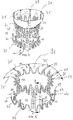
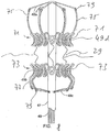
- FIG. 1 through FIG. 6 A first preferred embodiment of a tubular stent 29 incorporating various features of the invention is shown in FIG. 1 through FIG. 6 whereas FIG. 1a shows another preferred embodiment.
- the tubular stent 29 has a tubular deployment form with a longitudinal axis L and is optionally surrounded with a covering layer of biocompatible thin sheet material (not shown). It is designed to be deployed in a collapsed condition using a delivery implement where it is slidably disposed within or on a catheter that is caused to enter the body through a vein or through a cannula implanted intercostally in the chest, through which it is directed through an atrial wall or the left ventricular wall of the heart and, for example, and then through the orifice of the mitral valve.
- the tubular stent 29 can be made of wire-like material, which may be of circular, square, rectangular, oval or other cross section, of a shape-alloy material which has sufficient elasticity such that it can be manually crimped or contracted by applying radially inward directed forces to reduce the diameter of the tubular structure. More specifically, the tubular stent 29 is preferably made of a suitable metal or polymeric material that is biocompatible and has shape-memory properties. Parts of the stent or the complete stent can be resorbable.
- the radial force it will exert in tending to return to its "memory" shape can be controlled by varying the temperature difference between the Af and the temperature at which it will be deployed.
- the individual elements of the overall filamentous construction will usually have a square, rectangular, round or oval cross section that results from polishing after the structure has preferably been laser-cut from a single tube having an appropriate diameter proportional to the desired final valve size. After such cutting, the tubular stent 29 is formed to take its ultimate desired final shape and then treated with heat to set its "memory” so it will always return to this shape.
- the tubular stent 29 will have superelastic properties at and below normal body temperature so it will exhibit sufficient flexibility to allow it to be manipulated. Accordingly, as the tubular stent 29 gradually warms to body temperature, the tubular stent 29 slowly assumes its desired folded-over final shape which is shown in FIG. 2 .
- FIGS. 1 through 2 Illustrated in FIGS. 1 through 2 is a preferred embodiment of a tubular stent 29 that is designed to be incorporated as a part of a bioprosthetic heart valve.
- the tubular stent 29 is made of shape-memory material and is constructed to allow it to be expanded and/or contracted to exhibit different diameters.
- the stent 29 includes a proximal or apical ring (or ring portion) 71 and a basal or distal ring (or ring portion) 73, with multiple, in particular three, longitudinally extending posts 69, the ends of which are incorporated into these two, spaced-apart rings 71, 73 of the stent 29.
- the posts 69 are located equiangularly at 120° to one another by way of example.
- the posts 69 are equally long by way of example.
- the rings and the posts may be formed of generally wire form material as described hereinbefore with respect to the tubular stent 29; however, the stent 29 is again preferably laser-cut cut from a tube.
- Both rings are again of undulating design having proximal and distal tips, with the proximal ring 71 preferably having optionally slightly deeper loops. In the undulating shape, a plurality of loops can be arranged in generally sine wave fashion and extending in opposite directions as distal and proximal tips at each ring.
- the posts 69 may separate these two, spaced-apart rings 71, 73.
- the posts 69 may be the only elements (apart from the leaflets or other cover material) or metal or shape-memory elements that separate the rings 71, 73 or interconnect them with each other.
- the posts 69 may not be part of a mesh.
- the posts may not have an undulating structure themselves or at least not the undulating structure of one of the rings 71, 73.
- Circular apertures 37 are optionally provided near each end of the three posts; these facilitate the routing of control cords or strings for folding the stent 29.
- the construction is such that a plurality of distal arms 77 extend from certain of the spaced apart tips of the basal or distal ring 73 or any other section thereof, and a plurality of proximal arms 75 extend from tips of the apical or proximal ring 71 or any other section thereof.
- both the distal arms 77 and the proximal arms 75 extend into the same direction in an undeployed or crimped state of the tubular stent 29. In the example of FIG. 1 , the direction is towards the top of FIG. 1 , i. e., from distal to proximal.
- distal arms 77 are attached to distal tips of the distal or basal ring 73 only whereas the proximal arms 75 are attached to proximal tips of the top or proximal ring 71 only. This, however, is not meant as limiting.
- the proximal arms 75 can be of different length.
- arm 75a is longer than arm 75b.
- the brim 91 see FIG. 4 and FIG. 5 can be adapted to the particular conditions of the annulus into which the tubular stent 29 is to be implanted and which has to be sealed for avoiding blood reflux.
- the proximal arms 75 can be arranged so as to extend towards the distal end of the tubular stent 29 in a folded or crimped state.
- the proximal arms 75 will swing up into their position shown in FIG. 2 .
- the exemplary embodiment of FIG. 1a allows to have a relatively short folded tubular stent body 29 when compared to that of FIG. 1 with proximal arms extending upwards in the crimped state (with an identical height to that of FIG. 1 in the deployed state). This advantageously contributes to an easy manoeuvering of the tubular stent 29 when it is advanced by means of a catheter or the like.
- the proximal arms 75 are attached to the distal tips of the proximal ring 71 by way of example. However, they might be attached to the proximal tips of the proximal ring 71 in lieu, similar to what is shown in FIG. 1 .
- flexible sheet material 39 e.g. pericardium
- proximal or basal ring structure 71, 73 is preferably wrapped around sections of the proximal or basal ring structure 71, 73 to completely surround the ring portions between the posts 69 so that it extends distally interior of the ring within the stent 29 to form the leaflets (not shown).
- the distal or basal ring 73 of the stent 29 is formed, as can be seen in each FIGURE, have an outwardly concave C-shape contour. It essentially defines a partial toroidal surface as its circumference.
- the posts 69 have rows of parallel apertures 43 extending throughout their length through which chords or ties are passed the leaflets (not shown) in place within the interior of the stent 29 to create a working valve.
- Any suitable leaflet designs and attachment may be employed, such as those well-known in this art.
- leaflets of any of the general types shown in the following three Published U.S. Applications may be used: Nos. 2005/0075731 ; 2005/0113910 ; and 2005/0203617 .
- pledgets can be provided to reinforce the leaflets where there is an attachment to the posts 69.
- some or all of the leaflets are made of any artificial not biological material e.g. PTFE. In others, they are made of bioresorbable material that will be replaced by the body own tissue and cells over time.
- tubular stent 29 To implant the tubular stent 29 it is, in its tubular deployment form as shown in FIG. 1 , positioned about the exterior surface of a tubular delivery implement 47 (see FIG. 8 ), and the assembly is loaded into the distal end of a catheter (not shown).
- FIG. 2 shows the tubular stent 29 of FIG. 1 in a fully expanded state with no force or stress acting on the tubular stent material.
- the proximal arms 75 are lowered below a horizontal line (with respect to the illustration of FIG. 2 ).
- the angle ⁇ between the proximal arms 75 of FIG. 1 and the posts 69 may be about 70° or between 60° and 105°, preferably between 60° and 85°.
- FIG. 3 is a cross-sectional view taken generally along the line 7-7 of FIG. 2 .
- FIG. 3 shows the tubular stent 29 of FIG. 1 in a fully expanded state with no force or stress acting on the tubular stent material.
- the relative positions of the distal arms 77 with respect to the outer or radial end of the proximal tips do not change (nor substantially do not change). Therefore, the gap does not change or is not meant or intended to change upon crimping, deploying and the like.
- the distance d1 is - at least more or less - maintained while implanting the tubular stent 29. In any case, there will remain a gap during implanting.
- the gap d1 While implanting the tubular stent 29, the gap d1 is used for entangling or catching native structures of the heart as mentioned herein. That way, the distal arms 77 and the gap d1 together act as a hook for hooking the tubular stent 29 to native structures. That way, the tubular stent 29 is prevented from entering from the left ventricle into the left artrium once hooked to, e. g., chordae tenidneae.
- FIG. 3a shows the tubular FIGURE 2 in a non-fully deployed state. As can be seen, although the angle between the posts 69 and the distal arms 77 has markedly be widened, the gap d1 has not changed.
- the distal ring 73 or the particular undulations that form the distal ring 73 appear to be tilted or rotated about an imaginary rotation axis 70 extending into the drawing plane of FIG. 3 and FIG. 3a .
- tubular stent 29 may be used to clamp the native valve or parts thereof which are still connected to the orifice or annulus during implantation between proximal arms 75 and distal arms 77 both of which are arranged on the tubular stent 29 (and made of suitable material having, e. g., shape-memory capacity) so as to approach each other whenever possible.
- the proximal arms 75 may exert a longitudinal force onto the tubular stent body, pulling it into the left atrium.
- the proximal arms 75 and the distal arms 77 may act like a rivet when it comes to fixing the tubular stent 29 in the orifice or annulus.
- FIG. 4 corresponds to FIG. 1
- FIG. 5 corresponds to FIG. 2 .
- They show the tubular stent 29 of FIG. 1 and FIG. 2 , respectively. They differ from FIG. 1 and FIG. 2 in that they additionally disclose a rim or brim 91 that is attached to the proximal arms 75. It is noted that no mitral valve leaflets are shown in any of the FIGURES. They are omitted for the sake of clearness and readability only. Also, in FIG. 5 only one half of the brim 91 is illustrated.
- the brim 91 is supported by the proximal arms 75 along their entire or almost entire length.
- the arms 75 are in contact with the brim 91 by their lower or outer surfaces. However, they might also contact the brim 91 by their upper or inner surfaces, or by both the upper and the lower surfaces.
- the arms 75 are covered by the brim material on both of their sides. The arms 75 may, hence, be sandwiched between two layers of brim material.
- FIG. 6 shows how the arms 77 of the distal or basal ring structure 73 can be forced to assume a less everted position when comparted to their crimped or their undeployed position.
- the arms 77 can been forced to lower initially to a lower or more horizontal orientation compared to the one shown in FIG. 6 where the arms 77, at their free ends, are departed from the tubular main body of the stent 29.
- the force to do so is effected by, for example, a string 78 guided around the ring structure 73 that distorts the shape of the ring structure such that its distal end or opening of the distal ring 73 is narrower or smaller (not illustrated in FIG.
- retaining means such as apertures 87 for the string 78 might be provided, e. g. on the ring structure 73 itself. Also, such optional retaining means might be arranged to guide the string 78 on an inner side of the ring 73 or on an outer side or on a distal front side thereof.
- FIG. 6 shows how such apertures could be arranged at the distal front side of the distal ring 73, see reference numeral 87. Of course, more than just two such apertures 87 can be provided as well.
- the string 78 may be purse-like wound. It may be guided as shown in FIG. 6 , or at any other suitable position, for example through a number of apertures 87 that are provided on all or at least some of the distal tips of the distal ring structure 73.
- the tubular stent 29 or parts thereof can be folded. Once the tubular stent 29 is positioned and anchored and the implantation is regarded successful, one may remove the string 78 by disconnecting one end thereof and pulling back the other end.
- FIG. 7 shows an alternative embodiment to the one shown in FIG. 6 with respect to generating a force that temporarily departs the tips of free ends of the arms 77 from the tubular stent 29 body.
- a suitable, preferably flexible, pusher 80 - or a tip of an optional sleeve, if hard enough - is pushed in the direction of the arrow against the arms 77, preferably close to where they are attached to the distal ring structure 73.
- the pusher 80 which is shown partly cut, may be arranged so as to be slidable within the implement 47 or relative to the latter. In the embodiment of FIG. 7 , it is the pusher that forces the distal ring 73 to tilt or rotate which results in distal arms 77 deviating from the tubular main body or the posts 69 while maintaining the gap d1.
- FIG. 8 shows yet another alternative embodiment to the one shown in FIG. 6 with respect to generating a force that temporarily departs the tips or free ends of the arms 77 from the tubular stent body of which only its distal ring 73 and its proximal ring 71 are shown for enhanced clarity.
- the tubular stent 29 is shown attached to the delivery or implanting device 47, for example to a catheter or a catheter tip.
- Strings 49 that are used for expanding and deploying of the tubular stent 29 as strings 49b and 49d and, in this particular embodiment of FIG. 8 also as strings 49a and 49c for acting on at least one of arms 75 and arms 77, are also shown. They are all slidably routed through the catheter 47 or around rings 71 and 73 and, optionally, through eyelets or apertures 79 of arms 75 or 77. In the particular embodiment shown in FIG. 8 the gap d1 is obviously not maintained.
- the solutions of FIG. 6 through FIG. 8 allow for opening up the angle between the arms 77 and the tubular stent body for temporarily holding down the arms 77. In doing so, they allow the tubular stent 29 to become wider than the native mitral valve orifice in the heart by means of its arms 77. If carefully retracted with opened up arms 77, the tubular stent 29 is pressed or pulled against the native mitral valve leaflets pressed against the heart muscle forming a ring. Also, arms 77 are entangled and captured by the confluence of tendinous rope-like elements, known as chordae tendinae. As a result, the tubular stent 29 is stuck.
- the surgeon knows that the tubular stent 29 has reached its final position within the heart. This can be confirmed by imaging techniques.
- the proximal arms 75 begin to expand radially outward into a more or less horizontal position. If strings 49a are provided, they will be released by the surgeon so as to allow the arms 75 to lower.
- the opening angle between distal arms 77 and the longitudinal axis of the tubular stent 29 or the posts 69 thereof is between 35° to 70° or any value in between.
- a “horizontal position” as used herein refers to the illustrations of the FIGURES where the main body of the tubular stent 29 is shown as vertical; it goes without saying that "horizontal” relates to a line or plane that is rectangular to the longitudinal axis of the stent body or to the posts 69.
- tubular stent 29 can still be withdrawn from the mitral valve so long as the loops 49b, 49d are attached.
Landscapes
- Health & Medical Sciences (AREA)
- Engineering & Computer Science (AREA)
- Biomedical Technology (AREA)
- Cardiology (AREA)
- Oral & Maxillofacial Surgery (AREA)
- Transplantation (AREA)
- Heart & Thoracic Surgery (AREA)
- Vascular Medicine (AREA)
- Life Sciences & Earth Sciences (AREA)
- Animal Behavior & Ethology (AREA)
- General Health & Medical Sciences (AREA)
- Public Health (AREA)
- Veterinary Medicine (AREA)
- Prostheses (AREA)
Claims (13)
- Un stent tubulaire pliable et extensible (29) construit en matériau à mémoire de forme, implantable dans un coeur humain et comprenant :- des anneaux proximaux et distaux (71, 73) et au moins deux barres espacées (69) s'étendant axialement entre les dits anneaux (71, 73)- le dit anneau distal (73) comprenant une pluralité de bras distaux (77) connectés à l'anneau distal (73) par une extrémité du bras seulement et possédant une extrémité opposée libre ;- le dit anneau proximal (71) comprenant une pluralité de bras proximaux (75) connectés à l'anneau proximal (71) par une extrémité du bras seulement et possédant une extrémité opposée libre, les bras proximaux (75) étant construits de façon à former préférablement un angle d'environ 70°, ou compris entre 60° et 105°, encore plus préférablement compris entre 60° et 85°, par rapport à l'axe longitudinal du stent tubulaire (29) ;- où les bras distaux (77) sont attachés à l'anneau distal (73), ou forment partie de ce dernier, de façon à ce que un espace (d1) soit présent entre une section proximale ou une circonférence ou une enveloppe d'un motif ondulant de l'anneau distal (73) ou d'une section de celui-ci et du bras distal (77] ;caractérisé en ce que :- le stent tubulaire (29) est produit de façon à ce que l'espace (d1) ne s'élargisse pas ou ne devienne pas plus étroit lors du déploiement du stent tubulaire (29) de son état plié ou de façon à ce que l'espace (d1) maintienne sa largeur lors du déploiement.
- Un stent tubulaire pliable et extensible (29) selon la première revendication, où les bras distaux (77) sont connectés à l'extrémité distale ou aux pointes distales de l'anneau distal (73), préférablement de façon exclusive.
- Un stent tubulaire pliable et extensible (29) selon la première ou la seconde revendication, où les bras proximaux (75) sont connectés à l'extrémité proximale ou aux pointes proximales de l'anneau proximal (71), préférablement de façon exclusive.
- Un stent tubulaire pliable et extensible (29) selon l'une quelconque des revendications précédentes, ou au moins certains des bras distaux (77) et/ou certains des bras proximaux (75) comprennent des moyens (79) sur leur extrémité opposée libre permettant l'attachement de cordes (49a, 49c) pour contrôler et rétracter de façon individuelle certains ou chacun des bras (75, 77).
- Un stent tubulaire pliable et extensible (29) selon l'une quelconque des revendications précédentes, où au moins certains des bras proximaux (75) sont prévus pour adopter une position plus ou moins rectangulaire par rapport à un axe longitudinal (L) du stent tubulaire (29).
- Un stent tubulaire pliable et extensible (29) selon l'une quelconque des revendications précédentes, où au moins certains des bras proximaux (75) sont interconnectés au bord (91) d'un matériau biocompatible, préférablement un matériau biocompatible en feuillet.
- Un stent tubulaire pliable et extensible (29) selon l'une quelconque des revendications précédentes, formé de façon intégrale.
- Un stent tubulaire pliable et extensible (29) selon l'une quelconque des revendications précédentes, où l'anneau distal (73) est agencé de façon à adopter un diamètre plus faible à son extrémité distale qu'à son extrémité proximale si les extrémités libres des bras distaux (77) sont forcées de s'étendre davantage radialement en s'éloignant de l'axe longitudinal (L) ou de la ligne centrale du stent tubulaire (29).
- Une valve cardiaque comprenant un stent tubulaire (29) selon l'une quelconque des revendications précédentes, le stent tubulaire (29) étant interconnecté à une pluralité de feuillets flexibles disposés à l'intérieur dudit stent (29), les feuillets ouvrant pour permettre un flux de sang vers l'aval et fermant pour empêcher un flux de sang vers l'amont au travers de ceux-ci.
- Une valve cardiaque selon la revendication 9, où les feuillets sont agencés de façon à former une première cuspide, une seconde cuspide et une troisième cuspide.
- Une valve cardiaque selon l'une quelconque des revendications 9 à 10, le stent (29) étant connecté à une enveloppe extérieure faite d'un matériau biocompatible en feuille entourant les barres (69).
- Une valve cardiaque selon l'une quelconque des revendications 9 à 11, étant une valve cardiaque mitrale.
- Un système d'implantation pour implanter une valve cardiaque à un patient, le système comprenant une valve cardiaque selon l'une quelconque des revendications 9 à 12.
Priority Applications (7)
| Application Number | Priority Date | Filing Date | Title |
|---|---|---|---|
| EP14199956.5A EP3037064B1 (fr) | 2014-12-23 | 2014-12-23 | Remplacement de valvule mitrale à invasion minimale avec bord |
| PCT/EP2015/080582 WO2016097337A1 (fr) | 2014-12-19 | 2015-12-18 | Remplacement à effraction minimale de valvule mitrale comprenant un rebord |
| CN201580069238.2A CN107427364B (zh) | 2014-12-19 | 2015-12-18 | 具有边沿的微创二尖瓣瓣膜置换 |
| JP2017533301A JP2017538540A (ja) | 2014-12-19 | 2015-12-18 | 低侵襲性の鍔付き僧帽弁の置換術 |
| CA2971281A CA2971281C (fr) | 2014-12-19 | 2015-12-18 | Remplacement a effraction minimale de valvule mitrale comprenant un rebord |
| US15/623,790 US10463483B2 (en) | 2014-12-19 | 2017-06-15 | Minimally invasive mitral valve replacement with brim |
| JP2021012667A JP7072932B2 (ja) | 2014-12-19 | 2021-01-29 | 管状ステント、心臓弁及び搬送システム |
Applications Claiming Priority (1)
| Application Number | Priority Date | Filing Date | Title |
|---|---|---|---|
| EP14199956.5A EP3037064B1 (fr) | 2014-12-23 | 2014-12-23 | Remplacement de valvule mitrale à invasion minimale avec bord |
Publications (2)
| Publication Number | Publication Date |
|---|---|
| EP3037064A1 EP3037064A1 (fr) | 2016-06-29 |
| EP3037064B1 true EP3037064B1 (fr) | 2018-03-14 |
Family
ID=52130151
Family Applications (1)
| Application Number | Title | Priority Date | Filing Date |
|---|---|---|---|
| EP14199956.5A Active EP3037064B1 (fr) | 2014-12-19 | 2014-12-23 | Remplacement de valvule mitrale à invasion minimale avec bord |
Country Status (1)
| Country | Link |
|---|---|
| EP (1) | EP3037064B1 (fr) |
Cited By (45)
| Publication number | Priority date | Publication date | Assignee | Title |
|---|---|---|---|---|
| US10149756B2 (en) | 2008-09-29 | 2018-12-11 | Edwards Lifesciences Cardiaq Llc | Heart valve |
| US10179044B2 (en) | 2014-05-19 | 2019-01-15 | Edwards Lifesciences Cardiaq Llc | Replacement mitral valve |
| US10226335B2 (en) | 2015-06-22 | 2019-03-12 | Edwards Lifesciences Cardiaq Llc | Actively controllable heart valve implant and method of controlling same |
| US10350065B2 (en) | 2006-07-28 | 2019-07-16 | Edwards Lifesciences Cardiaq Llc | Percutaneous valve prosthesis and system and method for implanting the same |
| US10350066B2 (en) | 2015-08-28 | 2019-07-16 | Edwards Lifesciences Cardiaq Llc | Steerable delivery system for replacement mitral valve and methods of use |
| US10376363B2 (en) | 2015-04-30 | 2019-08-13 | Edwards Lifesciences Cardiaq Llc | Replacement mitral valve, delivery system for replacement mitral valve and methods of use |
| US10441412B2 (en) | 2009-04-15 | 2019-10-15 | Edwards Lifesciences Cardiaq Llc | Vascular implant and delivery system |
| US10456277B2 (en) | 2005-11-10 | 2019-10-29 | Edwards Lifesciences Cardiaq Llc | Percutaneous heart valve |
| US10485660B2 (en) | 2010-06-21 | 2019-11-26 | Edwards Lifesciences Cardiaq Llc | Replacement heart valve |
| US10575951B2 (en) | 2015-08-26 | 2020-03-03 | Edwards Lifesciences Cardiaq Llc | Delivery device and methods of use for transapical delivery of replacement mitral valve |
| US10583000B2 (en) | 2013-03-14 | 2020-03-10 | Edwards Lifesciences Cardiaq Llc | Prosthesis for atraumatically grasping intralumenal tissue and methods of delivery |
| US10610362B2 (en) | 2010-09-23 | 2020-04-07 | Edwards Lifesciences Cardiaq Llc | Replacement heart valves, delivery devices and methods |
| US10716664B2 (en) | 2013-03-14 | 2020-07-21 | Edwards Lifesciences Cardiaq Llc | Prosthesis for atraumatically grasping intralumenal tissue and methods of delivery |
| US10758345B2 (en) | 2015-08-26 | 2020-09-01 | Edwards Lifesciences Cardiaq Llc | Replacement heart valves and methods of delivery |
| US10813757B2 (en) | 2017-07-06 | 2020-10-27 | Edwards Lifesciences Corporation | Steerable rail delivery system |
| US10842620B2 (en) | 2015-06-23 | 2020-11-24 | Edwards Lifesciences Cardiaq Llc | Systems and methods for anchoring and sealing a prosthetic heart valve |
| US10856984B2 (en) | 2017-08-25 | 2020-12-08 | Neovasc Tiara Inc. | Sequentially deployed transcatheter mitral valve prosthesis |
| US10940001B2 (en) | 2012-05-30 | 2021-03-09 | Neovasc Tiara Inc. | Methods and apparatus for loading a prosthesis onto a delivery system |
| US10952849B2 (en) | 2014-02-21 | 2021-03-23 | Edwards Lifesciences Cardiaq Llc | Prosthesis, delivery device and methods of use |
| US11051934B2 (en) | 2018-02-28 | 2021-07-06 | Edwards Lifesciences Corporation | Prosthetic mitral valve with improved anchors and seal |
| US11058536B2 (en) | 2004-10-02 | 2021-07-13 | Edwards Lifesciences Cardiaq Llc | Method for replacement of heart valve |
| US11311376B2 (en) | 2019-06-20 | 2022-04-26 | Neovase Tiara Inc. | Low profile prosthetic mitral valve |
| US11357622B2 (en) | 2016-01-29 | 2022-06-14 | Neovase Tiara Inc. | Prosthetic valve for avoiding obstruction of outflow |
| US11389291B2 (en) | 2013-04-04 | 2022-07-19 | Neovase Tiara Inc. | Methods and apparatus for delivering a prosthetic valve to a beating heart |
| US11413139B2 (en) | 2011-11-23 | 2022-08-16 | Neovasc Tiara Inc. | Sequentially deployed transcatheter mitral valve prosthesis |
| US11419720B2 (en) | 2010-05-05 | 2022-08-23 | Neovasc Tiara Inc. | Transcatheter mitral valve prosthesis |
| US11464631B2 (en) | 2016-11-21 | 2022-10-11 | Neovasc Tiara Inc. | Methods and systems for rapid retraction of a transcatheter heart valve delivery system |
| US11491006B2 (en) | 2019-04-10 | 2022-11-08 | Neovasc Tiara Inc. | Prosthetic valve with natural blood flow |
| US11497602B2 (en) | 2012-02-14 | 2022-11-15 | Neovasc Tiara Inc. | Methods and apparatus for engaging a valve prosthesis with tissue |
| US11602429B2 (en) | 2019-04-01 | 2023-03-14 | Neovasc Tiara Inc. | Controllably deployable prosthetic valve |
| US11684474B2 (en) | 2018-01-25 | 2023-06-27 | Edwards Lifesciences Corporation | Delivery system for aided replacement valve recapture and repositioning post-deployment |
| US11737872B2 (en) | 2018-11-08 | 2023-08-29 | Neovasc Tiara Inc. | Ventricular deployment of a transcatheter mitral valve prosthesis |
| US11779742B2 (en) | 2019-05-20 | 2023-10-10 | Neovasc Tiara Inc. | Introducer with hemostasis mechanism |
| US11998447B2 (en) | 2019-03-08 | 2024-06-04 | Neovasc Tiara Inc. | Retrievable prosthesis delivery system |
| US12109111B2 (en) | 2015-12-15 | 2024-10-08 | Neovasc Tiara Inc. | Transseptal delivery system |
| US12295584B2 (en) | 2015-03-20 | 2025-05-13 | Edwards Lifesciences Corporation | Systems and methods for delivering an implantable device |
| US12364587B2 (en) | 2020-12-18 | 2025-07-22 | Edwards Lifesciences Corporation | Storage jar assembly for a prosthetic heart valve |
| US12403004B2 (en) | 2014-06-06 | 2025-09-02 | Edwards Lifesciences Corporation | Method for replacing a tricuspid valve |
| US12433743B2 (en) | 2009-12-04 | 2025-10-07 | Edwards Lifesciences Corporation | System for replacing a native valve of the heart |
| US12447013B2 (en) | 2009-04-29 | 2025-10-21 | The Cleveland Clinic Foundation | Apparatus and method for replacing a diseased cardiac valve |
| US12502276B2 (en) | 2011-05-16 | 2025-12-23 | Edwards Lifesciences Corporation | Inversion delivery device and method for a prosthesis |
| US12544222B2 (en) | 2019-02-04 | 2026-02-10 | Edwards Lifesciences Corporation | Guide wire apparatuses and methods |
| US12551207B2 (en) | 2008-11-21 | 2026-02-17 | Percutaneous Cardiovascular Solutions Pty Ltd | Heart valve prosthesis and method |
| US12599480B2 (en) | 2015-04-21 | 2026-04-14 | Edwards Lifesciences Corporation | Percutaneous mitral valve replacement device |
| US12611298B2 (en) | 2016-08-26 | 2026-04-28 | Edwards Lifesciences Corporation | Multi-portion replacement heart valve prosthesis |
Families Citing this family (57)
| Publication number | Priority date | Publication date | Assignee | Title |
|---|---|---|---|---|
| US20090276040A1 (en) | 2008-05-01 | 2009-11-05 | Edwards Lifesciences Corporation | Device and method for replacing mitral valve |
| WO2012087842A1 (fr) | 2010-12-23 | 2012-06-28 | The Foundry, Llc | Système de réparation et remplacement de valvule mitrale |
| WO2012177942A2 (fr) | 2011-06-21 | 2012-12-27 | Hanson Gifford, Iii | Dispositifs de valvule cardiaque prosthétiques et systèmes et procédés associés |
| US9655722B2 (en) | 2011-10-19 | 2017-05-23 | Twelve, Inc. | Prosthetic heart valve devices, prosthetic mitral valves and associated systems and methods |
| US11202704B2 (en) | 2011-10-19 | 2021-12-21 | Twelve, Inc. | Prosthetic heart valve devices, prosthetic mitral valves and associated systems and methods |
| US9039757B2 (en) | 2011-10-19 | 2015-05-26 | Twelve, Inc. | Prosthetic heart valve devices, prosthetic mitral valves and associated systems and methods |
| CN103889369B (zh) | 2011-10-19 | 2016-09-14 | 托尔福公司 | 用于心脏瓣膜置换术的装置 |
| JP6133309B2 (ja) | 2011-10-19 | 2017-05-24 | トゥエルヴ, インコーポレイテッド | 人工心臓弁デバイス |
| US9763780B2 (en) | 2011-10-19 | 2017-09-19 | Twelve, Inc. | Devices, systems and methods for heart valve replacement |
| US9579198B2 (en) | 2012-03-01 | 2017-02-28 | Twelve, Inc. | Hydraulic delivery systems for prosthetic heart valve devices and associated methods |
| US9439763B2 (en) | 2013-02-04 | 2016-09-13 | Edwards Lifesciences Corporation | Prosthetic valve for replacing mitral valve |
| CN105246431B (zh) | 2013-05-20 | 2018-04-06 | 托尔福公司 | 可植入心脏瓣膜装置、二尖瓣修复装置以及相关系统和方法 |
| CA2962747C (fr) | 2014-09-28 | 2023-02-28 | Cardiokinetix, Inc. | Appareils permettant de traiter un dysfonctionnement cardiaque |
| ES2989081T3 (es) | 2014-11-26 | 2024-11-25 | Edwards Lifesciences Corp | Válvula cardíaca protésica transcatéter y sistema de suministro |
| WO2017035002A1 (fr) | 2015-08-21 | 2017-03-02 | Twelve Inc. | Dispositifs de valves cardiaques implantables, dispositifs de réparation de valves mitrales et systèmes et procédés associés |
| US11833034B2 (en) | 2016-01-13 | 2023-12-05 | Shifamed Holdings, Llc | Prosthetic cardiac valve devices, systems, and methods |
| CN109069272A (zh) | 2016-04-29 | 2018-12-21 | 美敦力瓦斯科尔勒公司 | 具有带系绳的锚定件的假体心脏瓣膜设备以及相关联的系统和方法 |
| US10350062B2 (en) | 2016-07-21 | 2019-07-16 | Edwards Lifesciences Corporation | Replacement heart valve prosthesis |
| JP7057350B2 (ja) * | 2016-12-02 | 2022-04-19 | シノメド カーディオヴィータ テクノロジー インク | 薄型心臓弁システム |
| US10433961B2 (en) | 2017-04-18 | 2019-10-08 | Twelve, Inc. | Delivery systems with tethers for prosthetic heart valve devices and associated methods |
| US10575950B2 (en) | 2017-04-18 | 2020-03-03 | Twelve, Inc. | Hydraulic systems for delivering prosthetic heart valve devices and associated methods |
| US10702378B2 (en) | 2017-04-18 | 2020-07-07 | Twelve, Inc. | Prosthetic heart valve device and associated systems and methods |
| US10792151B2 (en) | 2017-05-11 | 2020-10-06 | Twelve, Inc. | Delivery systems for delivering prosthetic heart valve devices and associated methods |
| US10646338B2 (en) | 2017-06-02 | 2020-05-12 | Twelve, Inc. | Delivery systems with telescoping capsules for deploying prosthetic heart valve devices and associated methods |
| US10709591B2 (en) | 2017-06-06 | 2020-07-14 | Twelve, Inc. | Crimping device and method for loading stents and prosthetic heart valves |
| US10786352B2 (en) | 2017-07-06 | 2020-09-29 | Twelve, Inc. | Prosthetic heart valve devices and associated systems and methods |
| US10729541B2 (en) | 2017-07-06 | 2020-08-04 | Twelve, Inc. | Prosthetic heart valve devices and associated systems and methods |
| WO2019195860A2 (fr) | 2018-04-04 | 2019-10-10 | Vdyne, Llc | Dispositifs et procédés d'ancrage d'une valvule cardiaque transcathéter |
| WO2020041495A1 (fr) | 2018-08-21 | 2020-02-27 | Shifamed, Llc | Dispositifs, systèmes et méthodes pour valvule cardiaque prothétique |
| US11344413B2 (en) | 2018-09-20 | 2022-05-31 | Vdyne, Inc. | Transcatheter deliverable prosthetic heart valves and methods of delivery |
| US11278437B2 (en) | 2018-12-08 | 2022-03-22 | Vdyne, Inc. | Compression capable annular frames for side delivery of transcatheter heart valve replacement |
| US12186187B2 (en) | 2018-09-20 | 2025-01-07 | Vdyne, Inc. | Transcatheter deliverable prosthetic heart valves and methods of delivery |
| US10595994B1 (en) | 2018-09-20 | 2020-03-24 | Vdyne, Llc | Side-delivered transcatheter heart valve replacement |
| US10321995B1 (en) | 2018-09-20 | 2019-06-18 | Vdyne, Llc | Orthogonally delivered transcatheter heart valve replacement |
| US11071627B2 (en) | 2018-10-18 | 2021-07-27 | Vdyne, Inc. | Orthogonally delivered transcatheter heart valve frame for valve in valve prosthesis |
| US10912644B2 (en) | 2018-10-05 | 2021-02-09 | Shifamed Holdings, Llc | Prosthetic cardiac valve devices, systems, and methods |
| WO2020082039A1 (fr) | 2018-10-19 | 2020-04-23 | Shifamed Holdings, Llc | Dispositif médical réglable |
| US11109969B2 (en) | 2018-10-22 | 2021-09-07 | Vdyne, Inc. | Guidewire delivery of transcatheter heart valve |
| US11253359B2 (en) | 2018-12-20 | 2022-02-22 | Vdyne, Inc. | Proximal tab for side-delivered transcatheter heart valves and methods of delivery |
| WO2020146842A1 (fr) | 2019-01-10 | 2020-07-16 | Vdyne, Llc | Crochet d'ancrage pour prothèse de valvule cardiaque transcathéter à distribution latérale |
| US11273032B2 (en) | 2019-01-26 | 2022-03-15 | Vdyne, Inc. | Collapsible inner flow control component for side-deliverable transcatheter heart valve prosthesis |
| US11185409B2 (en) | 2019-01-26 | 2021-11-30 | Vdyne, Inc. | Collapsible inner flow control component for side-delivered transcatheter heart valve prosthesis |
| EP4729034A2 (fr) | 2019-03-05 | 2026-04-22 | VDyne, Inc. | Dispositifs de commande de régurgitation tricuspide pour prothèse de valvule cardiaque par transcathéter orthogonal |
| US11076956B2 (en) | 2019-03-14 | 2021-08-03 | Vdyne, Inc. | Proximal, distal, and anterior anchoring tabs for side-delivered transcatheter mitral valve prosthesis |
| US11173027B2 (en) | 2019-03-14 | 2021-11-16 | Vdyne, Inc. | Side-deliverable transcatheter prosthetic valves and methods for delivering and anchoring the same |
| EP3941391B1 (fr) | 2019-03-19 | 2024-12-04 | Shifamed Holdings, LLC | Dispositifs, systèmes pour valvule cardiaque prothétique |
| US12447014B2 (en) | 2019-04-12 | 2025-10-21 | Edwards Lifesciences Corporation | Valve with multi-part frame and associated resilient bridging features |
| ES2982566T3 (es) | 2019-04-23 | 2024-10-16 | Edwards Lifesciences Corp | Sistema de suministro de implantes motorizado |
| AU2020267390B2 (en) | 2019-05-04 | 2025-12-04 | Vdyne, Inc. | Cinch device and method for deployment of a side-delivered prosthetic heart valve in a native annulus |
| WO2021035032A1 (fr) | 2019-08-20 | 2021-02-25 | Vdyne, Inc. | Dispositifs d'administration et de récupération et procédés pour valvules prothétiques transcathéter à pose latérale |
| EP4684767A3 (fr) | 2019-08-26 | 2026-04-08 | VDyne, Inc. | Valvules prothétiques transcathéter à pose latérale |
| US11234813B2 (en) | 2020-01-17 | 2022-02-01 | Vdyne, Inc. | Ventricular stability elements for side-deliverable prosthetic heart valves and methods of delivery |
| JP7821166B2 (ja) | 2020-08-31 | 2026-02-26 | シファメド・ホールディングス・エルエルシー | 人工弁送達システム |
| JP7835754B2 (ja) | 2020-12-04 | 2026-03-25 | シファメド・ホールディングス・エルエルシー | 張り出し人工心弁送達デバイスおよびシステム |
| US12201521B2 (en) | 2021-03-22 | 2025-01-21 | Shifamed Holdings, Llc | Anchor position verification for prosthetic cardiac valve devices |
| EP4422552A1 (fr) | 2021-10-27 | 2024-09-04 | Edwards Lifesciences Corporation | Système et procédé de préhension et de chargement d'une valve cardiaque prothétique |
| EP4601585A1 (fr) | 2022-10-14 | 2025-08-20 | Vdyne, Inc. | Dispositifs et procédés de pose d'une valve cardiaque prothétique à l'aide d'un support supra-annulaire |
Family Cites Families (6)
| Publication number | Priority date | Publication date | Assignee | Title |
|---|---|---|---|---|
| US8308797B2 (en) | 2002-01-04 | 2012-11-13 | Colibri Heart Valve, LLC | Percutaneously implantable replacement heart valve device and method of making same |
| US20050075718A1 (en) | 2003-10-06 | 2005-04-07 | Nguyen Tuoc Tan | Minimally invasive valve replacement system |
| AU2005218326A1 (en) | 2004-02-27 | 2005-09-15 | Aortx, Inc. | Prosthetic heart valve delivery systems and methods |
| EP1991168B1 (fr) | 2006-02-16 | 2016-01-27 | Transcatheter Technologies GmbH | Remplacement d'une valvule cardiaque en une chirurgie mini-invasive |
| CN103889369B (zh) * | 2011-10-19 | 2016-09-14 | 托尔福公司 | 用于心脏瓣膜置换术的装置 |
| CA2901008C (fr) * | 2013-03-15 | 2021-06-22 | Twelve, Inc. | Dispositifs de valvule cardiaque prothetique, valvules mitrales prothetiques, et systemes et procedes associes |
-
2014
- 2014-12-23 EP EP14199956.5A patent/EP3037064B1/fr active Active
Non-Patent Citations (1)
| Title |
|---|
| None * |
Cited By (85)
| Publication number | Priority date | Publication date | Assignee | Title |
|---|---|---|---|---|
| US11058536B2 (en) | 2004-10-02 | 2021-07-13 | Edwards Lifesciences Cardiaq Llc | Method for replacement of heart valve |
| US11304803B2 (en) | 2004-10-02 | 2022-04-19 | Edwards Lifesciences Cardiaq Llc | Method for replacement of heart valve |
| US10456277B2 (en) | 2005-11-10 | 2019-10-29 | Edwards Lifesciences Cardiaq Llc | Percutaneous heart valve |
| US10350065B2 (en) | 2006-07-28 | 2019-07-16 | Edwards Lifesciences Cardiaq Llc | Percutaneous valve prosthesis and system and method for implanting the same |
| US11141265B2 (en) | 2006-07-28 | 2021-10-12 | Edwards Lifesciences Cardiaq Llc | Percutaneous valve prosthesis and system and method for implanting the same |
| US11589983B2 (en) | 2008-09-29 | 2023-02-28 | Edwards Lifesciences Cardiaq Llc | Heart valve |
| US11819404B2 (en) | 2008-09-29 | 2023-11-21 | Edwards Lifesciences Cardiaq Llc | Heart valve |
| US10149756B2 (en) | 2008-09-29 | 2018-12-11 | Edwards Lifesciences Cardiaq Llc | Heart valve |
| US10646334B2 (en) | 2008-09-29 | 2020-05-12 | Edwards Lifesciences Cardiaq Llc | Heart valve |
| US12551207B2 (en) | 2008-11-21 | 2026-02-17 | Percutaneous Cardiovascular Solutions Pty Ltd | Heart valve prosthesis and method |
| US11376119B2 (en) | 2009-04-15 | 2022-07-05 | Edwards Lifesciences Cardiaq Llc | Vascular implant and delivery system |
| US10441412B2 (en) | 2009-04-15 | 2019-10-15 | Edwards Lifesciences Cardiaq Llc | Vascular implant and delivery system |
| US12343252B2 (en) | 2009-04-15 | 2025-07-01 | Edwards Lifesciences Cardiaq Llc | Vascular implant and delivery system |
| US12447013B2 (en) | 2009-04-29 | 2025-10-21 | The Cleveland Clinic Foundation | Apparatus and method for replacing a diseased cardiac valve |
| US10524901B2 (en) | 2009-09-29 | 2020-01-07 | Edwards Lifesciences Cardiaq Llc | Replacement heart valve |
| US12433743B2 (en) | 2009-12-04 | 2025-10-07 | Edwards Lifesciences Corporation | System for replacing a native valve of the heart |
| US12611303B2 (en) | 2010-05-05 | 2026-04-28 | Neovasc Tiara Inc. | Transcatheter mitral valve prosthesis |
| US11419720B2 (en) | 2010-05-05 | 2022-08-23 | Neovasc Tiara Inc. | Transcatheter mitral valve prosthesis |
| US10639146B2 (en) | 2010-06-21 | 2020-05-05 | Edwards Lifesciences Cardiaq Llc | Replacement heart valve |
| US10485660B2 (en) | 2010-06-21 | 2019-11-26 | Edwards Lifesciences Cardiaq Llc | Replacement heart valve |
| US11452597B2 (en) | 2010-06-21 | 2022-09-27 | Edwards Lifesciences Cardiaq Llc | Replacement heart valve |
| US10881510B2 (en) | 2010-09-23 | 2021-01-05 | Edwards Lifesciences Cardiaq Llc | Replacement heart valves, delivery devices and methods |
| US10610362B2 (en) | 2010-09-23 | 2020-04-07 | Edwards Lifesciences Cardiaq Llc | Replacement heart valves, delivery devices and methods |
| US12318290B2 (en) | 2010-09-23 | 2025-06-03 | Edwards Lifesciences Cardiaq Llc | Replacement heart valves, delivery devices and methods |
| US12502276B2 (en) | 2011-05-16 | 2025-12-23 | Edwards Lifesciences Corporation | Inversion delivery device and method for a prosthesis |
| US11413139B2 (en) | 2011-11-23 | 2022-08-16 | Neovasc Tiara Inc. | Sequentially deployed transcatheter mitral valve prosthesis |
| US12053369B2 (en) | 2011-11-23 | 2024-08-06 | Neovasc Tiara Inc. | Sequentially deployed transcatheter mitral valve prosthesis |
| US12138159B2 (en) | 2012-02-14 | 2024-11-12 | Neovasc Tiara Inc. | Methods and apparatus for engaging a valve prosthesis with tissue |
| US11497602B2 (en) | 2012-02-14 | 2022-11-15 | Neovasc Tiara Inc. | Methods and apparatus for engaging a valve prosthesis with tissue |
| US11617650B2 (en) | 2012-05-30 | 2023-04-04 | Neovasc Tiara Inc. | Methods and apparatus for loading a prosthesis onto a delivery system |
| US11389294B2 (en) | 2012-05-30 | 2022-07-19 | Neovasc Tiara Inc. | Methods and apparatus for loading a prosthesis onto a delivery system |
| US10940001B2 (en) | 2012-05-30 | 2021-03-09 | Neovasc Tiara Inc. | Methods and apparatus for loading a prosthesis onto a delivery system |
| US10583000B2 (en) | 2013-03-14 | 2020-03-10 | Edwards Lifesciences Cardiaq Llc | Prosthesis for atraumatically grasping intralumenal tissue and methods of delivery |
| US11324591B2 (en) | 2013-03-14 | 2022-05-10 | Edwards Lifesciences Cardiaq Llc | Prosthesis for atraumatically grasping intralumenal tissue and methods of delivery |
| US10716664B2 (en) | 2013-03-14 | 2020-07-21 | Edwards Lifesciences Cardiaq Llc | Prosthesis for atraumatically grasping intralumenal tissue and methods of delivery |
| US11951001B2 (en) | 2013-03-14 | 2024-04-09 | Edwards Lifesciences Cardiaq Llc | Prosthesis for atraumatically grapsing intralumenal tissue and methods of delivery |
| US11389291B2 (en) | 2013-04-04 | 2022-07-19 | Neovase Tiara Inc. | Methods and apparatus for delivering a prosthetic valve to a beating heart |
| US10952849B2 (en) | 2014-02-21 | 2021-03-23 | Edwards Lifesciences Cardiaq Llc | Prosthesis, delivery device and methods of use |
| US11633279B2 (en) | 2014-02-21 | 2023-04-25 | Edwards Lifesciences Cardiaq Llc | Prosthesis, delivery device and methods of use |
| US12558219B2 (en) | 2014-02-21 | 2026-02-24 | Edwards Lifesciences Cardiaq Llc | Prosthesis, delivery device and methods of use |
| US12083011B2 (en) | 2014-05-19 | 2024-09-10 | Edwards Lifesciences Cardiaq Llc | Replacement heart valve |
| US10179044B2 (en) | 2014-05-19 | 2019-01-15 | Edwards Lifesciences Cardiaq Llc | Replacement mitral valve |
| US11045313B2 (en) | 2014-05-19 | 2021-06-29 | Edwards Lifesciences Cardiaq Llc | Replacement mitral valve |
| US12403004B2 (en) | 2014-06-06 | 2025-09-02 | Edwards Lifesciences Corporation | Method for replacing a tricuspid valve |
| US12295584B2 (en) | 2015-03-20 | 2025-05-13 | Edwards Lifesciences Corporation | Systems and methods for delivering an implantable device |
| US12599480B2 (en) | 2015-04-21 | 2026-04-14 | Edwards Lifesciences Corporation | Percutaneous mitral valve replacement device |
| US10376363B2 (en) | 2015-04-30 | 2019-08-13 | Edwards Lifesciences Cardiaq Llc | Replacement mitral valve, delivery system for replacement mitral valve and methods of use |
| US11389292B2 (en) | 2015-04-30 | 2022-07-19 | Edwards Lifesciences Cardiaq Llc | Replacement mitral valve, delivery system for replacement mitral valve and methods of use |
| US10226335B2 (en) | 2015-06-22 | 2019-03-12 | Edwards Lifesciences Cardiaq Llc | Actively controllable heart valve implant and method of controlling same |
| US11083576B2 (en) | 2015-06-22 | 2021-08-10 | Edwards Lifesciences Cardiaq Llc | Actively controllable heart valve implant and method of controlling same |
| US11844690B2 (en) | 2015-06-23 | 2023-12-19 | Edwards Lifesciences Cardiaq Llc | Systems and methods for anchoring and sealing a prosthetic heart valve |
| US10842620B2 (en) | 2015-06-23 | 2020-11-24 | Edwards Lifesciences Cardiaq Llc | Systems and methods for anchoring and sealing a prosthetic heart valve |
| US10758345B2 (en) | 2015-08-26 | 2020-09-01 | Edwards Lifesciences Cardiaq Llc | Replacement heart valves and methods of delivery |
| US11278405B2 (en) | 2015-08-26 | 2022-03-22 | Edwards Lifesciences Cardiaq Llc | Delivery device and methods of use for transapical delivery of replacement valve |
| US12023245B2 (en) | 2015-08-26 | 2024-07-02 | Edwards Lifesciences Cardiaq Llc | Delivery device and methods of use for transapical delivery of replacement valve |
| US10575951B2 (en) | 2015-08-26 | 2020-03-03 | Edwards Lifesciences Cardiaq Llc | Delivery device and methods of use for transapical delivery of replacement mitral valve |
| US12004949B2 (en) | 2015-08-26 | 2024-06-11 | Edwards Lifesciences Cardiaq Llc | Replacement heart valves and methods of delivery |
| US11253364B2 (en) | 2015-08-28 | 2022-02-22 | Edwards Lifesciences Cardiaq Llc | Steerable delivery system for replacement mitral valve and methods of use |
| US10350066B2 (en) | 2015-08-28 | 2019-07-16 | Edwards Lifesciences Cardiaq Llc | Steerable delivery system for replacement mitral valve and methods of use |
| US12161553B2 (en) | 2015-08-28 | 2024-12-10 | Edwards Lifesciences Cardiaq Llc | Steerable delivery system for replacement mitral valve and methods of use |
| US12109111B2 (en) | 2015-12-15 | 2024-10-08 | Neovasc Tiara Inc. | Transseptal delivery system |
| US11357622B2 (en) | 2016-01-29 | 2022-06-14 | Neovase Tiara Inc. | Prosthetic valve for avoiding obstruction of outflow |
| US12193932B2 (en) | 2016-01-29 | 2025-01-14 | Neovasc Tiara Inc. | Prosthetic valve for avoiding obstruction of outflow |
| US12611298B2 (en) | 2016-08-26 | 2026-04-28 | Edwards Lifesciences Corporation | Multi-portion replacement heart valve prosthesis |
| US11464631B2 (en) | 2016-11-21 | 2022-10-11 | Neovasc Tiara Inc. | Methods and systems for rapid retraction of a transcatheter heart valve delivery system |
| US12201524B2 (en) | 2016-11-21 | 2025-01-21 | Neovasc Tiara Inc. | Methods and systems for rapid retraction of a transcatheter heart valve delivery system |
| US10813757B2 (en) | 2017-07-06 | 2020-10-27 | Edwards Lifesciences Corporation | Steerable rail delivery system |
| US11123186B2 (en) | 2017-07-06 | 2021-09-21 | Edwards Lifesciences Corporation | Steerable delivery system and components |
| US12558218B2 (en) | 2017-07-06 | 2026-02-24 | Edwards Lifesciences Corporation | Steerable delivery system and components |
| US11883287B2 (en) | 2017-07-06 | 2024-01-30 | Edwards Lifesciences Corporation | Steerable rail delivery system |
| US10856984B2 (en) | 2017-08-25 | 2020-12-08 | Neovasc Tiara Inc. | Sequentially deployed transcatheter mitral valve prosthesis |
| US11793640B2 (en) | 2017-08-25 | 2023-10-24 | Neovasc Tiara Inc. | Sequentially deployed transcatheter mitral valve prosthesis |
| US11684474B2 (en) | 2018-01-25 | 2023-06-27 | Edwards Lifesciences Corporation | Delivery system for aided replacement valve recapture and repositioning post-deployment |
| US12440335B2 (en) | 2018-01-25 | 2025-10-14 | Edwards Lifesciences Corporation | Delivery system for aided replacement valve recapture and repositioning post-deployment |
| US11051934B2 (en) | 2018-02-28 | 2021-07-06 | Edwards Lifesciences Corporation | Prosthetic mitral valve with improved anchors and seal |
| US11737872B2 (en) | 2018-11-08 | 2023-08-29 | Neovasc Tiara Inc. | Ventricular deployment of a transcatheter mitral valve prosthesis |
| US12544222B2 (en) | 2019-02-04 | 2026-02-10 | Edwards Lifesciences Corporation | Guide wire apparatuses and methods |
| US11998447B2 (en) | 2019-03-08 | 2024-06-04 | Neovasc Tiara Inc. | Retrievable prosthesis delivery system |
| US11602429B2 (en) | 2019-04-01 | 2023-03-14 | Neovasc Tiara Inc. | Controllably deployable prosthetic valve |
| US12036117B2 (en) | 2019-04-10 | 2024-07-16 | Neovasc Tiara Inc. | Prosthetic valve with natural blood flow |
| US11491006B2 (en) | 2019-04-10 | 2022-11-08 | Neovasc Tiara Inc. | Prosthetic valve with natural blood flow |
| US11779742B2 (en) | 2019-05-20 | 2023-10-10 | Neovasc Tiara Inc. | Introducer with hemostasis mechanism |
| US11311376B2 (en) | 2019-06-20 | 2022-04-26 | Neovase Tiara Inc. | Low profile prosthetic mitral valve |
| US11931254B2 (en) | 2019-06-20 | 2024-03-19 | Neovasc Tiara Inc. | Low profile prosthetic mitral valve |
| US12364587B2 (en) | 2020-12-18 | 2025-07-22 | Edwards Lifesciences Corporation | Storage jar assembly for a prosthetic heart valve |
Also Published As
| Publication number | Publication date |
|---|---|
| EP3037064A1 (fr) | 2016-06-29 |
Similar Documents
| Publication | Publication Date | Title |
|---|---|---|
| US10463483B2 (en) | Minimally invasive mitral valve replacement with brim | |
| EP3037064A1 (fr) | Remplacement de valvule mitrale à invasion minimale avec bord | |
| US20250073029A1 (en) | Implantable Transcatheter Intracardiac Devices and Methods For Treating Incompetent Atrioventricular Valves | |
| US11576782B2 (en) | Implantable heart valve devices, mitral valve repair devices and associated systems and methods | |
| EP2583640B1 (fr) | Valvule cardiaque de remplacement minimalement invasive | |
| US11717401B2 (en) | Prosthetic heart valve assembly | |
| EP3471664B1 (fr) | Dispositif de traitement de la régurgitation mitrale | |
| JP6242924B2 (ja) | ステント、弁付きステントおよび方法ならびにその送達システム | |
| CN107405194B (zh) | 二尖瓣假体 | |
| JP6773416B2 (ja) | 僧帽弁置換のための人工弁 | |
| JP6545665B2 (ja) | 埋込可能な心臓弁デバイス、僧帽弁修復デバイス、および関連するシステムおよび方法 | |
| US9775704B2 (en) | Implantable valve prosthesis | |
| US20070027533A1 (en) | Cardiac valve annulus restraining device | |
| CN110831546A (zh) | 用于功能失调的心脏瓣膜的原位置换的带瓣膜支架和递送系统 | |
| EP3672525A1 (fr) | Système d'administration trans-septale ayant un segment de déviation et procédés d'utilisation | |
| CN114173713A (zh) | 经导管生物假体构件和支撑结构 | |
| CN222889075U (zh) | 用于假体瓣膜的小叶和假体心脏瓣膜 | |
| JP2024525974A (ja) | 経カテーテル的人工弁(thv)システム | |
| US11850149B2 (en) | Prosthetic heart valve delivery system |
Legal Events
| Date | Code | Title | Description |
|---|---|---|---|
| PUAI | Public reference made under article 153(3) epc to a published international application that has entered the european phase |
Free format text: ORIGINAL CODE: 0009012 |
|
| AK | Designated contracting states |
Kind code of ref document: A1 Designated state(s): AL AT BE BG CH CY CZ DE DK EE ES FI FR GB GR HR HU IE IS IT LI LT LU LV MC MK MT NL NO PL PT RO RS SE SI SK SM TR |
|
| AX | Request for extension of the european patent |
Extension state: BA ME |
|
| RAP1 | Party data changed (applicant data changed or rights of an application transferred) |
Owner name: VENUS MEDTECH (HANGZHOU), INC. |
|
| 17P | Request for examination filed |
Effective date: 20161227 |
|
| RBV | Designated contracting states (corrected) |
Designated state(s): AL AT BE BG CH CY CZ DE DK EE ES FI FR GB GR HR HU IE IS IT LI LT LU LV MC MK MT NL NO PL PT RO RS SE SI SK SM TR |
|
| GRAP | Despatch of communication of intention to grant a patent |
Free format text: ORIGINAL CODE: EPIDOSNIGR1 |
|
| INTG | Intention to grant announced |
Effective date: 20170728 |
|
| GRAS | Grant fee paid |
Free format text: ORIGINAL CODE: EPIDOSNIGR3 |
|
| GRAJ | Information related to disapproval of communication of intention to grant by the applicant or resumption of examination proceedings by the epo deleted |
Free format text: ORIGINAL CODE: EPIDOSDIGR1 |
|
| GRAL | Information related to payment of fee for publishing/printing deleted |
Free format text: ORIGINAL CODE: EPIDOSDIGR3 |
|
| GRAP | Despatch of communication of intention to grant a patent |
Free format text: ORIGINAL CODE: EPIDOSNIGR1 |
|
| INTC | Intention to grant announced (deleted) | ||
| INTG | Intention to grant announced |
Effective date: 20180104 |
|
| GRAA | (expected) grant |
Free format text: ORIGINAL CODE: 0009210 |
|
| AK | Designated contracting states |
Kind code of ref document: B1 Designated state(s): AL AT BE BG CH CY CZ DE DK EE ES FI FR GB GR HR HU IE IS IT LI LT LU LV MC MK MT NL NO PL PT RO RS SE SI SK SM TR |
|
| REG | Reference to a national code |
Ref country code: GB Ref legal event code: FG4D |
|
| REG | Reference to a national code |
Ref country code: CH Ref legal event code: EP Ref country code: AT Ref legal event code: REF Ref document number: 978116 Country of ref document: AT Kind code of ref document: T Effective date: 20180315 |
|
| REG | Reference to a national code |
Ref country code: IE Ref legal event code: FG4D |
|
| REG | Reference to a national code |
Ref country code: DE Ref legal event code: R096 Ref document number: 602014022277 Country of ref document: DE |
|
| REG | Reference to a national code |
Ref country code: CH Ref legal event code: NV Representative=s name: SERVOPATENT GMBH, CH |
|
| REG | Reference to a national code |
Ref country code: NL Ref legal event code: MP Effective date: 20180314 |
|
| REG | Reference to a national code |
Ref country code: LT Ref legal event code: MG4D |
|
| PG25 | Lapsed in a contracting state [announced via postgrant information from national office to epo] |
Ref country code: LT Free format text: LAPSE BECAUSE OF FAILURE TO SUBMIT A TRANSLATION OF THE DESCRIPTION OR TO PAY THE FEE WITHIN THE PRESCRIBED TIME-LIMIT Effective date: 20180314 Ref country code: HR Free format text: LAPSE BECAUSE OF FAILURE TO SUBMIT A TRANSLATION OF THE DESCRIPTION OR TO PAY THE FEE WITHIN THE PRESCRIBED TIME-LIMIT Effective date: 20180314 Ref country code: FI Free format text: LAPSE BECAUSE OF FAILURE TO SUBMIT A TRANSLATION OF THE DESCRIPTION OR TO PAY THE FEE WITHIN THE PRESCRIBED TIME-LIMIT Effective date: 20180314 Ref country code: NO Free format text: LAPSE BECAUSE OF FAILURE TO SUBMIT A TRANSLATION OF THE DESCRIPTION OR TO PAY THE FEE WITHIN THE PRESCRIBED TIME-LIMIT Effective date: 20180614 Ref country code: CY Free format text: LAPSE BECAUSE OF FAILURE TO SUBMIT A TRANSLATION OF THE DESCRIPTION OR TO PAY THE FEE WITHIN THE PRESCRIBED TIME-LIMIT Effective date: 20180314 |
|
| REG | Reference to a national code |
Ref country code: AT Ref legal event code: MK05 Ref document number: 978116 Country of ref document: AT Kind code of ref document: T Effective date: 20180314 |
|
| PG25 | Lapsed in a contracting state [announced via postgrant information from national office to epo] |
Ref country code: SE Free format text: LAPSE BECAUSE OF FAILURE TO SUBMIT A TRANSLATION OF THE DESCRIPTION OR TO PAY THE FEE WITHIN THE PRESCRIBED TIME-LIMIT Effective date: 20180314 Ref country code: LV Free format text: LAPSE BECAUSE OF FAILURE TO SUBMIT A TRANSLATION OF THE DESCRIPTION OR TO PAY THE FEE WITHIN THE PRESCRIBED TIME-LIMIT Effective date: 20180314 Ref country code: GR Free format text: LAPSE BECAUSE OF FAILURE TO SUBMIT A TRANSLATION OF THE DESCRIPTION OR TO PAY THE FEE WITHIN THE PRESCRIBED TIME-LIMIT Effective date: 20180615 Ref country code: BG Free format text: LAPSE BECAUSE OF FAILURE TO SUBMIT A TRANSLATION OF THE DESCRIPTION OR TO PAY THE FEE WITHIN THE PRESCRIBED TIME-LIMIT Effective date: 20180614 Ref country code: RS Free format text: LAPSE BECAUSE OF FAILURE TO SUBMIT A TRANSLATION OF THE DESCRIPTION OR TO PAY THE FEE WITHIN THE PRESCRIBED TIME-LIMIT Effective date: 20180314 |
|
| PG25 | Lapsed in a contracting state [announced via postgrant information from national office to epo] |
Ref country code: IT Free format text: LAPSE BECAUSE OF FAILURE TO SUBMIT A TRANSLATION OF THE DESCRIPTION OR TO PAY THE FEE WITHIN THE PRESCRIBED TIME-LIMIT Effective date: 20180314 Ref country code: RO Free format text: LAPSE BECAUSE OF FAILURE TO SUBMIT A TRANSLATION OF THE DESCRIPTION OR TO PAY THE FEE WITHIN THE PRESCRIBED TIME-LIMIT Effective date: 20180314 Ref country code: AL Free format text: LAPSE BECAUSE OF FAILURE TO SUBMIT A TRANSLATION OF THE DESCRIPTION OR TO PAY THE FEE WITHIN THE PRESCRIBED TIME-LIMIT Effective date: 20180314 Ref country code: NL Free format text: LAPSE BECAUSE OF FAILURE TO SUBMIT A TRANSLATION OF THE DESCRIPTION OR TO PAY THE FEE WITHIN THE PRESCRIBED TIME-LIMIT Effective date: 20180314 Ref country code: EE Free format text: LAPSE BECAUSE OF FAILURE TO SUBMIT A TRANSLATION OF THE DESCRIPTION OR TO PAY THE FEE WITHIN THE PRESCRIBED TIME-LIMIT Effective date: 20180314 Ref country code: PL Free format text: LAPSE BECAUSE OF FAILURE TO SUBMIT A TRANSLATION OF THE DESCRIPTION OR TO PAY THE FEE WITHIN THE PRESCRIBED TIME-LIMIT Effective date: 20180314 Ref country code: ES Free format text: LAPSE BECAUSE OF FAILURE TO SUBMIT A TRANSLATION OF THE DESCRIPTION OR TO PAY THE FEE WITHIN THE PRESCRIBED TIME-LIMIT Effective date: 20180314 |
|
| PG25 | Lapsed in a contracting state [announced via postgrant information from national office to epo] |
Ref country code: SM Free format text: LAPSE BECAUSE OF FAILURE TO SUBMIT A TRANSLATION OF THE DESCRIPTION OR TO PAY THE FEE WITHIN THE PRESCRIBED TIME-LIMIT Effective date: 20180314 Ref country code: AT Free format text: LAPSE BECAUSE OF FAILURE TO SUBMIT A TRANSLATION OF THE DESCRIPTION OR TO PAY THE FEE WITHIN THE PRESCRIBED TIME-LIMIT Effective date: 20180314 Ref country code: CZ Free format text: LAPSE BECAUSE OF FAILURE TO SUBMIT A TRANSLATION OF THE DESCRIPTION OR TO PAY THE FEE WITHIN THE PRESCRIBED TIME-LIMIT Effective date: 20180314 Ref country code: SK Free format text: LAPSE BECAUSE OF FAILURE TO SUBMIT A TRANSLATION OF THE DESCRIPTION OR TO PAY THE FEE WITHIN THE PRESCRIBED TIME-LIMIT Effective date: 20180314 |
|
| REG | Reference to a national code |
Ref country code: DE Ref legal event code: R097 Ref document number: 602014022277 Country of ref document: DE |
|
| PG25 | Lapsed in a contracting state [announced via postgrant information from national office to epo] |
Ref country code: PT Free format text: LAPSE BECAUSE OF FAILURE TO SUBMIT A TRANSLATION OF THE DESCRIPTION OR TO PAY THE FEE WITHIN THE PRESCRIBED TIME-LIMIT Effective date: 20180716 |
|
| PLBE | No opposition filed within time limit |
Free format text: ORIGINAL CODE: 0009261 |
|
| STAA | Information on the status of an ep patent application or granted ep patent |
Free format text: STATUS: NO OPPOSITION FILED WITHIN TIME LIMIT |
|
| PG25 | Lapsed in a contracting state [announced via postgrant information from national office to epo] |
Ref country code: DK Free format text: LAPSE BECAUSE OF FAILURE TO SUBMIT A TRANSLATION OF THE DESCRIPTION OR TO PAY THE FEE WITHIN THE PRESCRIBED TIME-LIMIT Effective date: 20180314 |
|
| 26N | No opposition filed |
Effective date: 20181217 |
|
| PG25 | Lapsed in a contracting state [announced via postgrant information from national office to epo] |
Ref country code: SI Free format text: LAPSE BECAUSE OF FAILURE TO SUBMIT A TRANSLATION OF THE DESCRIPTION OR TO PAY THE FEE WITHIN THE PRESCRIBED TIME-LIMIT Effective date: 20180314 |
|
| PG25 | Lapsed in a contracting state [announced via postgrant information from national office to epo] |
Ref country code: MC Free format text: LAPSE BECAUSE OF FAILURE TO SUBMIT A TRANSLATION OF THE DESCRIPTION OR TO PAY THE FEE WITHIN THE PRESCRIBED TIME-LIMIT Effective date: 20180314 Ref country code: LU Free format text: LAPSE BECAUSE OF NON-PAYMENT OF DUE FEES Effective date: 20181223 |
|
| REG | Reference to a national code |
Ref country code: IE Ref legal event code: MM4A |
|
| REG | Reference to a national code |
Ref country code: BE Ref legal event code: MM Effective date: 20181231 |
|
| PG25 | Lapsed in a contracting state [announced via postgrant information from national office to epo] |
Ref country code: IE Free format text: LAPSE BECAUSE OF NON-PAYMENT OF DUE FEES Effective date: 20181223 |
|
| PG25 | Lapsed in a contracting state [announced via postgrant information from national office to epo] |
Ref country code: BE Free format text: LAPSE BECAUSE OF NON-PAYMENT OF DUE FEES Effective date: 20181231 |
|
| PG25 | Lapsed in a contracting state [announced via postgrant information from national office to epo] |
Ref country code: MT Free format text: LAPSE BECAUSE OF NON-PAYMENT OF DUE FEES Effective date: 20181223 |
|
| PG25 | Lapsed in a contracting state [announced via postgrant information from national office to epo] |
Ref country code: TR Free format text: LAPSE BECAUSE OF FAILURE TO SUBMIT A TRANSLATION OF THE DESCRIPTION OR TO PAY THE FEE WITHIN THE PRESCRIBED TIME-LIMIT Effective date: 20180314 |
|
| REG | Reference to a national code |
Ref country code: CH Ref legal event code: PCAR Free format text: NEW ADDRESS: WANNERSTRASSE 9/1, 8045 ZUERICH (CH) |
|
| PG25 | Lapsed in a contracting state [announced via postgrant information from national office to epo] |
Ref country code: MK Free format text: LAPSE BECAUSE OF NON-PAYMENT OF DUE FEES Effective date: 20180314 Ref country code: HU Free format text: LAPSE BECAUSE OF FAILURE TO SUBMIT A TRANSLATION OF THE DESCRIPTION OR TO PAY THE FEE WITHIN THE PRESCRIBED TIME-LIMIT; INVALID AB INITIO Effective date: 20141223 |
|
| PG25 | Lapsed in a contracting state [announced via postgrant information from national office to epo] |
Ref country code: IS Free format text: LAPSE BECAUSE OF FAILURE TO SUBMIT A TRANSLATION OF THE DESCRIPTION OR TO PAY THE FEE WITHIN THE PRESCRIBED TIME-LIMIT Effective date: 20180714 |
|
| PGFP | Annual fee paid to national office [announced via postgrant information from national office to epo] |
Ref country code: CH Payment date: 20230104 Year of fee payment: 9 |
|
| REG | Reference to a national code |
Ref country code: CH Ref legal event code: PL |
|
| PG25 | Lapsed in a contracting state [announced via postgrant information from national office to epo] |
Ref country code: CH Free format text: LAPSE BECAUSE OF NON-PAYMENT OF DUE FEES Effective date: 20231231 |
|
| PG25 | Lapsed in a contracting state [announced via postgrant information from national office to epo] |
Ref country code: CH Free format text: LAPSE BECAUSE OF NON-PAYMENT OF DUE FEES Effective date: 20231231 |
|
| PGFP | Annual fee paid to national office [announced via postgrant information from national office to epo] |
Ref country code: GB Payment date: 20251218 Year of fee payment: 12 |
|
| PGFP | Annual fee paid to national office [announced via postgrant information from national office to epo] |
Ref country code: FR Payment date: 20251218 Year of fee payment: 12 |
|
| PGFP | Annual fee paid to national office [announced via postgrant information from national office to epo] |
Ref country code: DE Payment date: 20251222 Year of fee payment: 12 |