EP3037620A1 - Inhibition de l'injection de gaz dans un puits d'injection d'eau - Google Patents
Inhibition de l'injection de gaz dans un puits d'injection d'eau Download PDFInfo
- Publication number
- EP3037620A1 EP3037620A1 EP14200349.0A EP14200349A EP3037620A1 EP 3037620 A1 EP3037620 A1 EP 3037620A1 EP 14200349 A EP14200349 A EP 14200349A EP 3037620 A1 EP3037620 A1 EP 3037620A1
- Authority
- EP
- European Patent Office
- Prior art keywords
- water
- water injection
- well
- injection valve
- valve
- Prior art date
- Legal status (The legal status is an assumption and is not a legal conclusion. Google has not performed a legal analysis and makes no representation as to the accuracy of the status listed.)
- Withdrawn
Links
- XLYOFNOQVPJJNP-UHFFFAOYSA-N water Substances O XLYOFNOQVPJJNP-UHFFFAOYSA-N 0.000 title claims abstract description 138
- 238000002347 injection Methods 0.000 title claims abstract description 88
- 239000007924 injection Substances 0.000 title claims abstract description 88
- 230000002401 inhibitory effect Effects 0.000 title claims abstract description 8
- 239000012530 fluid Substances 0.000 claims description 28
- 238000004519 manufacturing process Methods 0.000 claims description 26
- 241000191291 Abies alba Species 0.000 claims description 16
- 238000000034 method Methods 0.000 claims description 16
- 230000015572 biosynthetic process Effects 0.000 claims description 13
- 239000007789 gas Substances 0.000 claims description 12
- VNWKTOKETHGBQD-UHFFFAOYSA-N methane Chemical compound C VNWKTOKETHGBQD-UHFFFAOYSA-N 0.000 claims description 12
- 210000002445 nipple Anatomy 0.000 claims description 7
- 239000003345 natural gas Substances 0.000 claims description 5
- 238000005260 corrosion Methods 0.000 claims description 4
- 230000007797 corrosion Effects 0.000 claims description 4
- 230000005484 gravity Effects 0.000 claims description 3
- 239000010779 crude oil Substances 0.000 claims 5
- RWSOTUBLDIXVET-UHFFFAOYSA-N Dihydrogen sulfide Chemical compound S RWSOTUBLDIXVET-UHFFFAOYSA-N 0.000 claims 1
- 230000001590 oxidative effect Effects 0.000 abstract description 2
- 239000004215 Carbon black (E152) Substances 0.000 description 4
- 229930195733 hydrocarbon Natural products 0.000 description 4
- 150000002430 hydrocarbons Chemical class 0.000 description 4
- QVGXLLKOCUKJST-UHFFFAOYSA-N atomic oxygen Chemical compound [O] QVGXLLKOCUKJST-UHFFFAOYSA-N 0.000 description 3
- 239000001301 oxygen Substances 0.000 description 3
- 229910052760 oxygen Inorganic materials 0.000 description 3
- 230000006835 compression Effects 0.000 description 2
- 238000007906 compression Methods 0.000 description 2
- 239000000470 constituent Substances 0.000 description 1
- 238000011109 contamination Methods 0.000 description 1
- 230000002706 hydrostatic effect Effects 0.000 description 1
- 239000007788 liquid Substances 0.000 description 1
- 238000011084 recovery Methods 0.000 description 1
Images
Classifications
-
- E—FIXED CONSTRUCTIONS
- E21—EARTH OR ROCK DRILLING; MINING
- E21B—EARTH OR ROCK DRILLING; OBTAINING OIL, GAS, WATER, SOLUBLE OR MELTABLE MATERIALS OR A SLURRY OF MINERALS FROM WELLS
- E21B34/00—Valve arrangements for boreholes or wells
- E21B34/02—Valve arrangements for boreholes or wells in well heads
-
- E—FIXED CONSTRUCTIONS
- E21—EARTH OR ROCK DRILLING; MINING
- E21B—EARTH OR ROCK DRILLING; OBTAINING OIL, GAS, WATER, SOLUBLE OR MELTABLE MATERIALS OR A SLURRY OF MINERALS FROM WELLS
- E21B33/00—Sealing or packing boreholes or wells
- E21B33/02—Surface sealing or packing
- E21B33/03—Well heads; Setting-up thereof
- E21B33/035—Well heads; Setting-up thereof specially adapted for underwater installations
- E21B33/037—Protective housings therefor
- E21B33/0375—Corrosion protection means
-
- E—FIXED CONSTRUCTIONS
- E21—EARTH OR ROCK DRILLING; MINING
- E21B—EARTH OR ROCK DRILLING; OBTAINING OIL, GAS, WATER, SOLUBLE OR MELTABLE MATERIALS OR A SLURRY OF MINERALS FROM WELLS
- E21B43/00—Methods or apparatus for obtaining oil, gas, water, soluble or meltable materials or a slurry of minerals from wells
- E21B43/16—Enhanced recovery methods for obtaining hydrocarbons
- E21B43/20—Displacing by water
Definitions
- the invention relates to a method and system for inhibiting air and/or other corrosive and/or oxidising gas injection into an underground water injection well.
- hydrocarbon oil or gas When hydrocarbon oil or gas is produced from an underground oil and/or gas containing formation, it may occur that after a period of time water is concurrently produced with the produced oil or gas.
- the produced water may be contaminated with oil and/or other constituents, and it may be decided to re-inject the produced water into the earth formation. Such reinjection also may improve recovery of hydrocarbon fluid from the earth formation and may help maintaining the production rate of the field over a longer period of time.
- the document "Water Injection & Produced Water Reinjection at Ravva” by Cairn India Limited discloses a method of injecting produced water into an earth formation.
- the injection water is pumped by electrical submersible pumps from a depth of around 40 m and fed to a water surge tank.
- the surge tank is gas blanketed using natural gas to prevent oxygen contamination in the injection water.
- a system for inhibiting gas injection into an underground water injection well comprising:
- the reservoir is arranged to allow water of the body of water to flow into the conduit via said inlet by gravity.
- the control device may be operative to open the water injection valve when the level of the body of water reaches a selected level above said minimum level.
- the water injection valve is located in a wellhead at the upper end of the borehole.
- the conduit may include a water injection tubing connected to a hanger nipple suspended in the wellhead, wherein the water injection valve is positioned in the hanger nipple.
- a Christmas tree is positioned above the wellhead, wherein the water injection valve is controlled via a control line extending through a housing of the Christmas tree and below a lower master valve of the Christmas tree.
- the water injection valve may be a hydraulic valve, wherein the control line is a hydraulic control line.
- the invention also relates to a method of inhibiting gas injection into an underground water injection well, the method comprising:
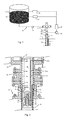
- FIG. 1 there is shown a water injection well 1 extending into an earth formation 2, the well 1 being provided with a wellhead 4 and a Christmas tree 6 at surface 8.
- a conduit in the form of production tubing 10 extends into the well 1 to a depth where water is to be injected into the earth formation 2.
- the production tubing 10 is fluidly connected to a reservoir 12 via the Christmas tree 6 and a conduit 14 interconnecting the reservoir 12 and the Christmas tree 6 at an inlet 15 thereof.
- the reservoir 12 contains a body of water 16 that has been produced from a hydrocarbon fluid production well (not shown).
- a liquid line solenoid valve 18 is provided in the conduit 14 as an emergency shutdown valve.
- a water injection valve 20 is provided at the upper end of the production tubing 10 and below a lower master valve 22 of the Christmas tree 6.
- the water injection valve 20 is hydraulically operated by a pump 24 and is arranged to selectively allow water to flow from the reservoir 12 into the production tubing 10 via the conduit 14.
- a control device 26 is provided for controlling operation of the water injection valve 20 via the pump 24 in dependence of the water level in the reservoir 12.
- the reservoir 12 is provided with a first gauge 28 that provides a first signal representing a minimum level of the body of water 16. The minimum level is selected slightly higher than the vertical level of the inlet of the water injection valve 20.
- the control device 26 is programmed to induce the pump 24 to close the water injection valve 20 upon receiving the first signal.
- the reservoir 12 is provided with a second gauge 30 providing a second signal representing a selected upper level of the body of water 16 above the minimum level.
- the control device 26 is programmed to induce the pump 24 to open the water injection valve 20 upon receiving the second signal.
- the assembly includes a tubing head 32 in which the production tubing 10 is suspended on a tubing hanger nipple 34.
- a tubing head adapter 36 is arranged between the lower master valve 22 and the tubing head 32.
- the lower master valve 22 may be a conventional gate valve with a gate member (not shown) arranged to slide in transverse direction between an open position and a closed position.
- the water injection valve 20 comprises a cylindrical housing 38 extending into the hanger nipple 34 and having an annular shoulder 40 that rests on a corresponding annular shoulder 42 of the hanger nipple 34.
- a tubular upper portion 44 of the housing 38 extends into the lower master valve 22 and is sealed to a cylindrical inner surface 46 thereof by annular seals 42, 44.
- An interior space 48 of the tubular upper portion 44 is in fluid communication with the production tubing 10 via a number of ports 50 provided in the housing 38.
- the water injection valve 20 comprises a valve member 52 axially movable in a valve chamber 54 of the housing 38 between an open position and a closed position.
- a valve member 52 axially movable in a valve chamber 54 of the housing 38 between an open position and a closed position.
- water is allowed to flow from the interior space 48 via the ports 50 into the production tubing 10.
- the closed position the upper end of the valve member 52 abuts against an annular seat 56 of the housing 38 so as to prevent flow of water from the interior space 48 via the ports 50 into the production tubing 10.
- a compression spring 58 is provided to bias the valve member 52 to the closed position.
- the valve member 52 is at the lower end thereof provided with a piston 60 arranged in a fluid chamber 62 of the housing 38.
- the fluid chamber 62 is fluidly connected to the pump 24 via a fluid channel 64 having a first channel portion 64a passing through the housing 38.
- a second portion 64b of the fluid channel 64 passes through the lower master valve 22, below the gate member thereof.
- the piston 60, the fluid chamber 62 and the fluid channel 64 are arranged so that the valve member 52 moves to the open position when hydraulic fluid is pumped into the fluid chamber 62 via the fluid channel 64.
- control device 26 induces pump 24 to pump hydraulic fluid into the fluid chamber 62 via fluid channel 64 so as to move the valve member 52 to the open position. Water flows then from the reservoir 12 via the conduit 14 and the Christmas tree 6 into the interior space 48 of the housing 38. From there the water flow via the ports 50 and the production tubing 10 into an open lower section of the well 1 and then further into the earth formation 2.
- the first gauge 28 Upon the water level in the reservoir 12 reaching the minimum level, the first gauge 28 sends the first signal to the control device 26 which thereby induces the pump 24 to decrease the fluid pressure in the fluid chamber 62. As a result, the compression spring 58 urges the valve member 52 to the closed position so that the ports 50 become closed. The flow of water from the reservoir 12 into the production tubing 10 is thereby stopped. Due to the minimum level of water in the reservoir being slightly higher than the vertical level of the inlet of the water injection valve 20, there will be a small hydrostatic column of water present above the water injection valve 20 after the flow of water has been stopped. Water that already has entered the production tubing 10 continues flowing downwards and thereby causes a reduced fluid pressure in an upper portion of the production tubing 10.
- the second gauge 30 sends the second signal to the control device 16 which then induces the pump 24 to open the water injection valve 20 so as to allow water to flow again from the reservoir 12 into the production tubing 10.
- the water level in the reservoir is maintained between the selected minimum level and the selected upper level.
- the hydraulic control line for controlling the water injection valve may be provided at a separate spool of the wellhead or at a special entrance of the Christmas tree.
- the invention provides an improved method and system for inhibiting air and/or other corrosive and/or oxidising gas injection into an underground water injection well (1) because a control device (26) automatically closes a water injection valve(20) when the injection water level in an injection water storage reservoir (12) drops below a selected minimum level.
Landscapes
- Life Sciences & Earth Sciences (AREA)
- Engineering & Computer Science (AREA)
- Geology (AREA)
- Mining & Mineral Resources (AREA)
- Physics & Mathematics (AREA)
- Environmental & Geological Engineering (AREA)
- Fluid Mechanics (AREA)
- General Life Sciences & Earth Sciences (AREA)
- Geochemistry & Mineralogy (AREA)
- Pipeline Systems (AREA)
Priority Applications (1)
| Application Number | Priority Date | Filing Date | Title |
|---|---|---|---|
| EP14200349.0A EP3037620A1 (fr) | 2014-12-24 | 2014-12-24 | Inhibition de l'injection de gaz dans un puits d'injection d'eau |
Applications Claiming Priority (1)
| Application Number | Priority Date | Filing Date | Title |
|---|---|---|---|
| EP14200349.0A EP3037620A1 (fr) | 2014-12-24 | 2014-12-24 | Inhibition de l'injection de gaz dans un puits d'injection d'eau |
Publications (1)
| Publication Number | Publication Date |
|---|---|
| EP3037620A1 true EP3037620A1 (fr) | 2016-06-29 |
Family
ID=52232020
Family Applications (1)
| Application Number | Title | Priority Date | Filing Date |
|---|---|---|---|
| EP14200349.0A Withdrawn EP3037620A1 (fr) | 2014-12-24 | 2014-12-24 | Inhibition de l'injection de gaz dans un puits d'injection d'eau |
Country Status (1)
| Country | Link |
|---|---|
| EP (1) | EP3037620A1 (fr) |
Citations (2)
| Publication number | Priority date | Publication date | Assignee | Title |
|---|---|---|---|---|
| US2357189A (en) * | 1942-06-08 | 1944-08-29 | Salt Water Control Inc | Flow regulation apparatus for brine injection wells |
| US4009756A (en) * | 1975-09-24 | 1977-03-01 | Trw, Incorporated | Method and apparatus for flooding of oil-bearing formations by downward inter-zone pumping |
-
2014
- 2014-12-24 EP EP14200349.0A patent/EP3037620A1/fr not_active Withdrawn
Patent Citations (2)
| Publication number | Priority date | Publication date | Assignee | Title |
|---|---|---|---|---|
| US2357189A (en) * | 1942-06-08 | 1944-08-29 | Salt Water Control Inc | Flow regulation apparatus for brine injection wells |
| US4009756A (en) * | 1975-09-24 | 1977-03-01 | Trw, Incorporated | Method and apparatus for flooding of oil-bearing formations by downward inter-zone pumping |
Non-Patent Citations (1)
| Title |
|---|
| "Water Injection & Produced Water Reinjection at Ravva", CAIRN INDIA LIMITED |
Similar Documents
| Publication | Publication Date | Title |
|---|---|---|
| US7150325B2 (en) | ROV retrievable sea floor pump | |
| US8881825B2 (en) | Barrier side pocket mandrel and gas life valve | |
| US11142994B2 (en) | Buoyancy assist tool with annular cavity and piston | |
| US12116869B2 (en) | Subsea methane production assembly | |
| RU2671370C2 (ru) | Система с переключающим клапаном и способ добычи газа | |
| CN111771039A (zh) | 带有排气系统的电动沉没泵 | |
| US20210372223A1 (en) | Buoyancy assist tool with annular cavity and piston | |
| RU2394978C1 (ru) | Способ освоения и эксплуатации скважин | |
| US20210148184A1 (en) | Buoyancy assist tool with degradable plug | |
| US10337296B2 (en) | Gas lift assembly | |
| US20210123317A1 (en) | Buoyancy assist tool with overlapping membranes | |
| US11236592B2 (en) | Valve system | |
| US7195072B2 (en) | Installation of downhole electrical power cable and safety valve assembly | |
| RU2576729C1 (ru) | Установка для одновременно-раздельной эксплуатации нескольких залежей одной скважиной (варианты) | |
| RU2539486C1 (ru) | Способ разработки нефтяной залежи скважинами с горизонтальным окончанием | |
| RU2728065C2 (ru) | Способ искусственного подъема | |
| EP3037620A1 (fr) | Inhibition de l'injection de gaz dans un puits d'injection d'eau | |
| AU2017234997B2 (en) | Pressure sensing system | |
| US20260036025A1 (en) | Systems and methods for well lifting operation assistance | |
| US20170226831A1 (en) | Downhole lift gas injection system | |
| US9435180B2 (en) | Annular gas lift valve | |
| US9725995B2 (en) | Bottle chamber gas lift systems, apparatuses, and methods thereof | |
| CN118591677A (zh) | 用于捕集和储存碳的井口系统和方法 | |
| EP1253283A1 (fr) | Procédé de mise en place d'un élément tubulaire de puits |
Legal Events
| Date | Code | Title | Description |
|---|---|---|---|
| PUAI | Public reference made under article 153(3) epc to a published international application that has entered the european phase |
Free format text: ORIGINAL CODE: 0009012 |
|
| AK | Designated contracting states |
Kind code of ref document: A1 Designated state(s): AL AT BE BG CH CY CZ DE DK EE ES FI FR GB GR HR HU IE IS IT LI LT LU LV MC MK MT NL NO PL PT RO RS SE SI SK SM TR |
|
| AX | Request for extension of the european patent |
Extension state: BA ME |
|
| STAA | Information on the status of an ep patent application or granted ep patent |
Free format text: STATUS: THE APPLICATION IS DEEMED TO BE WITHDRAWN |
|
| 18D | Application deemed to be withdrawn |
Effective date: 20170103 |