EP3037622B1 - Moteur à turbine à aubes directrices en avant de ses pales de soufflante - Google Patents
Moteur à turbine à aubes directrices en avant de ses pales de soufflante Download PDFInfo
- Publication number
- EP3037622B1 EP3037622B1 EP15202683.7A EP15202683A EP3037622B1 EP 3037622 B1 EP3037622 B1 EP 3037622B1 EP 15202683 A EP15202683 A EP 15202683A EP 3037622 B1 EP3037622 B1 EP 3037622B1
- Authority
- EP
- European Patent Office
- Prior art keywords
- fan
- rotor
- engine
- turbine engine
- pusher
- Prior art date
- Legal status (The legal status is an assumption and is not a legal conclusion. Google has not performed a legal analysis and makes no representation as to the accuracy of the status listed.)
- Active
Links
Images



Classifications
-
- F—MECHANICAL ENGINEERING; LIGHTING; HEATING; WEAPONS; BLASTING
- F01—MACHINES OR ENGINES IN GENERAL; ENGINE PLANTS IN GENERAL; STEAM ENGINES
- F01D—NON-POSITIVE DISPLACEMENT MACHINES OR ENGINES, e.g. STEAM TURBINES
- F01D1/00—Non-positive-displacement machines or engines, e.g. steam turbines
- F01D1/02—Non-positive-displacement machines or engines, e.g. steam turbines with stationary working-fluid guiding means and bladed or like rotor, e.g. multi-bladed impulse steam turbines
-
- F—MECHANICAL ENGINEERING; LIGHTING; HEATING; WEAPONS; BLASTING
- F01—MACHINES OR ENGINES IN GENERAL; ENGINE PLANTS IN GENERAL; STEAM ENGINES
- F01D—NON-POSITIVE DISPLACEMENT MACHINES OR ENGINES, e.g. STEAM TURBINES
- F01D17/00—Regulating or controlling by varying flow
- F01D17/10—Final actuators
- F01D17/105—Final actuators by passing part of the fluid
-
- F—MECHANICAL ENGINEERING; LIGHTING; HEATING; WEAPONS; BLASTING
- F01—MACHINES OR ENGINES IN GENERAL; ENGINE PLANTS IN GENERAL; STEAM ENGINES
- F01D—NON-POSITIVE DISPLACEMENT MACHINES OR ENGINES, e.g. STEAM TURBINES
- F01D1/00—Non-positive-displacement machines or engines, e.g. steam turbines
- F01D1/02—Non-positive-displacement machines or engines, e.g. steam turbines with stationary working-fluid guiding means and bladed or like rotor, e.g. multi-bladed impulse steam turbines
- F01D1/023—Non-positive-displacement machines or engines, e.g. steam turbines with stationary working-fluid guiding means and bladed or like rotor, e.g. multi-bladed impulse steam turbines the working-fluid being divided into several separate flows ; several separate fluid flows being united in a single flow; the machine or engine having provision for two or more different possible fluid flow paths
-
- F—MECHANICAL ENGINEERING; LIGHTING; HEATING; WEAPONS; BLASTING
- F01—MACHINES OR ENGINES IN GENERAL; ENGINE PLANTS IN GENERAL; STEAM ENGINES
- F01D—NON-POSITIVE DISPLACEMENT MACHINES OR ENGINES, e.g. STEAM TURBINES
- F01D25/00—Component parts, details, or accessories, not provided for in, or of interest apart from, other groups
- F01D25/24—Casings; Casing parts, e.g. diaphragms, casing fastenings
-
- F—MECHANICAL ENGINEERING; LIGHTING; HEATING; WEAPONS; BLASTING
- F01—MACHINES OR ENGINES IN GENERAL; ENGINE PLANTS IN GENERAL; STEAM ENGINES
- F01D—NON-POSITIVE DISPLACEMENT MACHINES OR ENGINES, e.g. STEAM TURBINES
- F01D5/00—Blades; Blade-carrying members; Heating, heat-insulating, cooling or antivibration means on the blades or the members
- F01D5/02—Blade-carrying members, e.g. rotors
-
- F—MECHANICAL ENGINEERING; LIGHTING; HEATING; WEAPONS; BLASTING
- F01—MACHINES OR ENGINES IN GENERAL; ENGINE PLANTS IN GENERAL; STEAM ENGINES
- F01D—NON-POSITIVE DISPLACEMENT MACHINES OR ENGINES, e.g. STEAM TURBINES
- F01D7/00—Rotors with blades adjustable in operation; Control thereof
-
- F—MECHANICAL ENGINEERING; LIGHTING; HEATING; WEAPONS; BLASTING
- F01—MACHINES OR ENGINES IN GENERAL; ENGINE PLANTS IN GENERAL; STEAM ENGINES
- F01D—NON-POSITIVE DISPLACEMENT MACHINES OR ENGINES, e.g. STEAM TURBINES
- F01D9/00—Stators
- F01D9/02—Nozzles; Nozzle boxes; Stator blades; Guide conduits, e.g. individual nozzles
- F01D9/04—Nozzles; Nozzle boxes; Stator blades; Guide conduits, e.g. individual nozzles forming ring or sector
- F01D9/041—Nozzles; Nozzle boxes; Stator blades; Guide conduits, e.g. individual nozzles forming ring or sector using blades
-
- F—MECHANICAL ENGINEERING; LIGHTING; HEATING; WEAPONS; BLASTING
- F02—COMBUSTION ENGINES; HOT-GAS OR COMBUSTION-PRODUCT ENGINE PLANTS
- F02C—GAS-TURBINE PLANTS; AIR INTAKES FOR JET-PROPULSION PLANTS; CONTROLLING FUEL SUPPLY IN AIR-BREATHING JET-PROPULSION PLANTS
- F02C3/00—Gas-turbine plants characterised by the use of combustion products as the working fluid
- F02C3/04—Gas-turbine plants characterised by the use of combustion products as the working fluid having a turbine driving a compressor
- F02C3/107—Gas-turbine plants characterised by the use of combustion products as the working fluid having a turbine driving a compressor with two or more rotors connected by power transmission
-
- F—MECHANICAL ENGINEERING; LIGHTING; HEATING; WEAPONS; BLASTING
- F02—COMBUSTION ENGINES; HOT-GAS OR COMBUSTION-PRODUCT ENGINE PLANTS
- F02C—GAS-TURBINE PLANTS; AIR INTAKES FOR JET-PROPULSION PLANTS; CONTROLLING FUEL SUPPLY IN AIR-BREATHING JET-PROPULSION PLANTS
- F02C3/00—Gas-turbine plants characterised by the use of combustion products as the working fluid
- F02C3/14—Gas-turbine plants characterised by the use of combustion products as the working fluid characterised by the arrangement of the combustion chamber in the plant
-
- F—MECHANICAL ENGINEERING; LIGHTING; HEATING; WEAPONS; BLASTING
- F05—INDEXING SCHEMES RELATING TO ENGINES OR PUMPS IN VARIOUS SUBCLASSES OF CLASSES F01-F04
- F05D—INDEXING SCHEME FOR ASPECTS RELATING TO NON-POSITIVE-DISPLACEMENT MACHINES OR ENGINES, GAS-TURBINES OR JET-PROPULSION PLANTS
- F05D2220/00—Application
- F05D2220/30—Application in turbines
- F05D2220/32—Application in turbines in gas turbines
- F05D2220/323—Application in turbines in gas turbines for aircraft propulsion, e.g. jet engines
-
- F—MECHANICAL ENGINEERING; LIGHTING; HEATING; WEAPONS; BLASTING
- F05—INDEXING SCHEMES RELATING TO ENGINES OR PUMPS IN VARIOUS SUBCLASSES OF CLASSES F01-F04
- F05D—INDEXING SCHEME FOR ASPECTS RELATING TO NON-POSITIVE-DISPLACEMENT MACHINES OR ENGINES, GAS-TURBINES OR JET-PROPULSION PLANTS
- F05D2240/00—Components
- F05D2240/10—Stators
- F05D2240/12—Fluid guiding means, e.g. vanes
- F05D2240/128—Nozzles
-
- F—MECHANICAL ENGINEERING; LIGHTING; HEATING; WEAPONS; BLASTING
- F05—INDEXING SCHEMES RELATING TO ENGINES OR PUMPS IN VARIOUS SUBCLASSES OF CLASSES F01-F04
- F05D—INDEXING SCHEME FOR ASPECTS RELATING TO NON-POSITIVE-DISPLACEMENT MACHINES OR ENGINES, GAS-TURBINES OR JET-PROPULSION PLANTS
- F05D2240/00—Components
- F05D2240/20—Rotors
- F05D2240/24—Rotors for turbines
-
- F—MECHANICAL ENGINEERING; LIGHTING; HEATING; WEAPONS; BLASTING
- F05—INDEXING SCHEMES RELATING TO ENGINES OR PUMPS IN VARIOUS SUBCLASSES OF CLASSES F01-F04
- F05D—INDEXING SCHEME FOR ASPECTS RELATING TO NON-POSITIVE-DISPLACEMENT MACHINES OR ENGINES, GAS-TURBINES OR JET-PROPULSION PLANTS
- F05D2240/00—Components
- F05D2240/60—Shafts
-
- F—MECHANICAL ENGINEERING; LIGHTING; HEATING; WEAPONS; BLASTING
- F05—INDEXING SCHEMES RELATING TO ENGINES OR PUMPS IN VARIOUS SUBCLASSES OF CLASSES F01-F04
- F05D—INDEXING SCHEME FOR ASPECTS RELATING TO NON-POSITIVE-DISPLACEMENT MACHINES OR ENGINES, GAS-TURBINES OR JET-PROPULSION PLANTS
- F05D2260/00—Function
- F05D2260/60—Fluid transfer
- F05D2260/606—Bypassing the fluid
Definitions
- This invention relates generally to a turbine engine and, more particularly, to a turbine engine with a bypass fan.
- turbine engines for propelling an aircraft are known in the art.
- An example of one such turbine engine is a turbofan engine which includes a fan forward of its core.
- Another example of a turbine engine is a pusher fan engine which includes a fan aft of its core.
- Still another example of a turbine engine is a propfan engine which includes an uncovered or unshrouded propeller (instead of a fan) aft of its core. While each of the foregoing turbine engine types have various advantages, there is still a need in the art for improved turbine engine efficiency as well as reduced turbine engine weight and costs.
- GB 1088360A and GB 1290485A represent prior art disclosures.
- EP1835147A discloses a pusher fan engine according to the preamble of claim 1.
- the guide vanes may be pitched in an opposite direction from the fan blades.
- the guide vanes for example, may be pitched in a substantially equal but opposite direction from the fan blades.
- the bypass flowpath extending form an inlet to a nozzle.
- the guide vanes are within the bypass flowpath and between the inlet and the fan blades.
- a turbine engine core is included and axially forward of the fan rotor.
- This turbine engine core may be configured as or otherwise include a multi-spool turbine engine core.
- a bifurcation may extend radially through the bypass flowpath and between the inlet and the fan rotor. This bifurcation may be configured as a substantially non-structural component of the pusher fan engine.
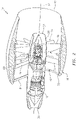
- the turbine engine core 12 may be configured as a multi-spool turbine engine core.
- the turbine engine core 12 of FIG. 3 includes a low speed spool, a high speed spool and a combustor 18.
- the low speed spool includes a low speed shaft 20 which connects a low pressure compressor (LPC) rotor 22 to a low pressure turbine (LPT) rotor 24.
- the high speed spool includes a high speed shaft 26 which connects a high pressure compressor (HPC) rotor 28 to a high pressure turbine (HPT) rotor 30.
- LPC low pressure compressor
- HPT high pressure turbine
- the rotors 22, 28, 30 and 24 are arranged sequentially along an axial centerline 32 of the turbine engine 10 between a forward core airflow inlet 34 and an aft core airflow exhaust nozzle 36.
- the combustor 18 is arranged axially between the high pressure compressor rotor 28 and the high pressure turbine rotor 30.
- the pusher fan system 14 is arranged downstream and aft of the turbine engine core 12.
- the pusher fan system 14 includes a fan rotor 38 connected to a turbine rotor 40.
- This turbine rotor 40 may be configured as a low pressure free turbine rotor and arranged next to and downstream of the low pressure turbine rotor 24 and, thus, aft of the turbine engine core 12.
- the turbine rotor 40 may be connected to the fan rotor 38 through one or more shafts 42 and 44 and a gear train 46.
- the gear train 46 may be an epicyclic transmission such as a planetary gear system or a star gear system.
- the gear train 46 may be configured as a reduction transmission such that the turbine rotor 40 rotates at a faster speed than the fan rotor 38.
- the fan rotor 38 is arranged aft of the turbine rotor 40 and the turbine engine core 12.
- the fan rotor 38 includes a plurality of fan blades 48. These fan blades 48 are arranged around a fan rotor hub 50 and within an annular bypass flowpath 52. Referring to FIG. 4 , each of the fan blades 48 may be pivotally connected to the fan rotor hub 50. With this configuration, a pitch of each fan blade 48 may be changed using an actuation system 54 within the fan rotor hub 50.
- the actuation system 54 may be configured for limited variable pitch. Alternatively, the actuation system 54 may be configured for full variable pitch where, for example, the fan blade pitch may be completely reversed.
- actuations systems for pivoting fan blades 48 are known in the art and the present disclosure is not limited to any particular types or configurations thereof. Of course, in other embodiments, one or more of the fan blades 48 may be fixedly connected to the fan rotor hub 50.
- the fan rotor hub 50 of FIG. 4 includes an inner platform 56 and an outer platform 58.
- the fan rotor hub 50 also includes a plurality of rotor vanes 60. Each of these rotor vanes 60 extends radially between and is connected to the inner platform 56 and the outer platform 58.
- One or more of the rotor vanes 60 may be hollow such that an actuation shaft 62 may extend radially therethrough from the actuation system 54 to a respective one of the fan blades 48. In this manner, the actuation system 54 may pivot the fan blades 48 by twisting the actuation shafts 62 in order to change the fan blade pitch.
- This air which may be referred to as “core air”
- core air is compressed by the compressor rotors 22 and 28 and directed into a combustion chamber 64 in the combustor 18.
- Fuel is injected into the combustion chamber 64 and mixed with the compressed air to provide a fuel-air mixture.
- This fuel air mixture is ignited and combustion products thereof flow through and sequentially cause the turbine rotors 30, 24 and 40 to rotate.
- the rotation of the turbine rotors 30 and 24 respectively drive rotation of the compressor rotors 28 and 22 and, thus, compression of the air received from the core airflow inlet 34.
- the rotation of the turbine rotor 40 drives rotation of the fan rotor 38, which propels bypass air through and out of the bypass flowpath 52.
- the propulsion of the bypass air may account for a majority of thrust generated by the turbine engine 10, e.g., more than seventy-five percent (75%) of turbine engine thrust.
- the turbine engine 10 of the present disclosure is not limited to the foregoing exemplary thrust ratio.
- the inner casing 66 may be configured with or as part of an inner cowling, e.g., a core cowling or nacelle.
- the inner casing 66 houses one or more components of the turbine engine core 12.
- the inner casing 66 may also house one or more components of the pusher fan system 14 such as, for example, the turbine rotor 40 and the gear train 46 (see FIG. 2 ).
- the inner casing 66 may be configured as a single unitary case. Alternatively, the inner casing 66 may include a plurality of cases which are attached to one another.
- the outer casing 68 houses at least the fan rotor 38. A forward portion of the outer casing 68 also axially overlaps an aft portion of the inner casing 66.
- the outer casing 68 may be configured as a single unitary case. Alternatively, the outer casing 68 may include a plurality of cases which are attached to one another.
- the inner casing 66 is connected to the outer casing 68 through a plurality of guide vanes 74.
- guide vanes 74 may each be configured as a structural guide vane.
- Each of the guide vanes 74 may structurally tie the inner casing 66 and the outer casing 68 together, i.e., be configured to transfer radial, axial and/or tangential loads between the casings 66 and 68.
- the guide vanes 74 are arranged circumferentially around the centerline 32 and may be axially aligned in a single array. Each of the guide vanes 74 extends radially between and is attached to the inner casing 66 and the outer casing 68. Each of the guide vanes 74, for example, may be mechanically fastened, welded, brazed and/or adhered to the inner casing 66 and/or the outer casing 68. With such a configuration, the guide vanes 74 provide a single plane mount system between the inner casing 66 and the outer casing 68.
- the turbine engine 10 of the present disclosure is not limited to the foregoing exemplary mount system nor single plane mount systems in general.
- each of the guide vanes 74 is configured as an airfoil.
- each of the guide vanes 74 has opposing sides 76 and 78 that extend longitudinally between a leading edge 80 and a trailing edge 82.
- the side 76 is generally concave.
- the side 78 is generally convex.
- the present disclosure is not limited to any particular guide vane 74 shapes or configurations.
- Each of the fan blades 48 may have a pitch that facilitates swirling the air in a second (e.g., counter-clockwise) direction during at least, for example, one (e.g., forward cruise) mode of operation.
- the pitch of the fan blades 48 may be substantially equal to, but opposite, the pitch of the guide vanes 74 during that mode of operation.
- the swirl imparted to the air by the fan blades 48 may substantially (e.g., completely or almost completely) counteract the swirl imparted to the air by the guide vanes 74 such that the air being propelled by the fan blades 48 out of the bypass flowpath 52 travels along a substantially axial trajectory. Exhausting the bypass air from the nozzle 72 (see FIGS. 2 and 3 ) along such a substantially axial trajectory may increase turbine engine thrust and/or efficiency.
- the bypass air may enter the bypass inlet 70 in a generally axial direction.
- the velocity into the guide vanes 74 is shown as C 1 .
- the guide vanes 74 are chambered and impart swirl in a first direction.
- the velocity exiting the guide vanes 74 in the stationary frame of reference is shown as C 2 .
- the fan blades 48 have tangential velocity U in the opposite direction of the guide vane swirl.
- the relative velocity into the fan blades is W 2 , the vector sum of vane exit velocity C 2 and wheel velocity U.
- the fan blades 48 are cambered in the opposite sense of the guide vanes 74, such that swirl velocity may be reduced across the blades 48.
- the relative velocity at blade exit is shown as W 3 , and the blade exit velocity in the stationary frame, C 3 , may be substantially axial.
- Each of the guide vanes 74 may be configured as a unitary hollow or solid body, e.g., a monolithic guide vane.
- one or more of the guide vanes 74 may each include a structural strut that extends radially through a hollow (e.g., substantially non-structural) airfoil.
- a bifurcation 84 such as a pylon may be disposed within and extend radially through the bypass flowpath 52.
- This bifurcation 84 may be arranged axially between the bypass inlet 70 and the fan rotor 38 and, for example, forward of, or axially aligned with, the guide vanes 74.
- the bifurcation 84 may be configured as a non-structural component such that substantially no loads are transferred therethrough between the inner casing 66 and the outer casing 68.
- the bifurcation 84 may also or alternatively structurally tie the inner casing 66 to the outer casing 68.
- the bifurcation 84 is a structural component
- one or more of the guide vanes 74 may be configured as a non-structural component.
Landscapes
- Engineering & Computer Science (AREA)
- Mechanical Engineering (AREA)
- General Engineering & Computer Science (AREA)
- Chemical & Material Sciences (AREA)
- Combustion & Propulsion (AREA)
- Physics & Mathematics (AREA)
- Fluid Mechanics (AREA)
- Structures Of Non-Positive Displacement Pumps (AREA)
Claims (14)
- Moteur à soufflante propulsive comprenant :une nacelle (16) ayant une entrée (70) de dérivation et une buse (72), présentant un trajet d'écoulement de dérivation (52) s'étendant de l'entrée (70) de dérivation à la buse (72) ;un rotor de soufflante (38) propulsive comportant une pluralité d'ailettes de soufflante (48) dans le trajet d'écoulement de dérivation (52) ;une pluralité d'aubes directrices (74) dans le trajet d'écoulement de dérivation (52) et entre l'entrée (70) et les ailettes de soufflante (48), dans lequel chaque aube directrice (74) a des côtés opposés concaves et convexes (76, 78) qui s'étendent longitudinalement entre un bord d'attaque (80) et un bord de fuite (82) ;un noyau de moteur à turbine (12) axialement en avant du rotor de soufflante (38) propulsive ;un rotor de turbine libre (40) ; caractérisé par un train d'engrenages (46) reliant le rotor de turbine libre (40) au rotor de soufflante (38) propulsive.
- Moteur à soufflante propulsive selon la revendication 1, dans lequel les aubes directrices (74) sont inclinées dans une direction sensiblement égale mais opposée aux ailettes de soufflante (48).
- Moteur à soufflante propulsive selon la revendication 1 ou 2, dans lequel au moins une des ailettes de soufflante (48) est configurée comme une ailette de soufflante (48) à pas variable.
- Moteur à soufflante propulsive selon la revendication 1, 2 ou 3, dans lequel la nacelle (16) comporte un carter intérieur (66) et un carter extérieur (68), et les carters intérieur (66) et extérieur (68) sont structurellement liés ensemble par un système de montage qui comporte au moins une des aubes directrices (74).
- Moteur à soufflante propulsive selon une quelconque revendication précédente, dans lequel la nacelle (16) comporte un carter intérieur (66) et un carter extérieur (68), et dans lequel le carter extérieur (68) est structurellement lié au carter intérieur (66) à travers au moins l'une des aubes directrices (74).
- Moteur à soufflante propulsive selon une quelconque revendication précédente, comprenant en outre une bifurcation (84) s'étendant à travers le trajet d'écoulement de dérivation (52) et entre l'entrée (70) et le rotor de soufflante (38), dans lequel, éventuellement, la bifurcation (84) est configurée comme un composant sensiblement non structurel du moteur à soufflante propulsive.
- Moteur à turbine comprenant :une nacelle (16) présentant un circuit de dérivation (52) ;un rotor de soufflante (38) propulsive comportant une pluralité d'ailettes de soufflante (48) dans le trajet d'écoulement de dérivation (52), le rotor de soufflante (38) étant configuré pour propulser de l'air hors du trajet d'écoulement de dérivation (52) ;une pluralité d'aubes directrices (74) configurées pour diriger l'air vers le rotor de soufflante (38), dans lequel chaque aube directrice (74) a des côtés opposés concaves et convexes (76, 78) qui s'étendent longitudinalement entre un bord d'attaque (80) et un bord de fuite (82) ;un noyau de moteur à turbine (12) axialement en avant du rotor de soufflante (38) propulsive ;un rotor de turbine libre (40) ; caractérisé par un train d'engrenages (46) reliant le rotor de turbine libre (40) au rotor de soufflante (38) propulsive.
- Moteur à turbine selon la revendication 7, dans lequel le rotor de soufflante (38) est configuré pour faire tourbillonner l'air dans un premier sens, et les aubes directrices (74) sont configurées pour faire tourbillonner l'air dans un second sens opposé au premier sens.
- Moteur à turbine selon la revendication 7 ou 8, dans lequel le trajet d'écoulement de dérivation (52) s'étend d'une entrée (70) à une buse (72) ; et
les aubes directrices (74) sont dans le trajet d'écoulement de dérivation (52) et entre l'entrée (70) et les ailettes de soufflante (48). - Moteur à soufflante propulsive ou moteur à turbine selon une quelconque revendication précédente, dans lequel les aubes directrices (74) sont inclinées dans une direction opposée aux ailettes de soufflante (48).
- Moteur à soufflante propulsive ou moteur à turbine selon une quelconque revendication précédente, dans lequel au moins l'une des aubes directrices (74) est une aube directrice structurelle.
- Moteur à soufflante propulsive ou moteur à turbine selon une quelconque revendication précédente, dans lequel le noyau de moteur à turbine (12) comprend un noyau de moteur à turbine à corps multiples.
- Moteur à soufflante propulsive ou moteur à turbine selon une quelconque revendication précédente, dans lequel le train d'engrenages (46) est configuré comme une transmission de réduction de sorte que le rotor de turbine (40) tourne à une vitesse plus rapide que le rotor de soufflante (38).
- Moteur à soufflante propulsive ou moteur à turbine selon une quelconque revendication précédente, dans lequel le train d'engrenages (46) est une transmission épicycloïdale telle qu'un système d'engrenage planétaire ou un système de réducteur épicycloïdal planétaire.
Applications Claiming Priority (1)
| Application Number | Priority Date | Filing Date | Title |
|---|---|---|---|
| US201462096662P | 2014-12-24 | 2014-12-24 |
Publications (2)
| Publication Number | Publication Date |
|---|---|
| EP3037622A1 EP3037622A1 (fr) | 2016-06-29 |
| EP3037622B1 true EP3037622B1 (fr) | 2022-09-21 |
Family
ID=55066398
Family Applications (1)
| Application Number | Title | Priority Date | Filing Date |
|---|---|---|---|
| EP15202683.7A Active EP3037622B1 (fr) | 2014-12-24 | 2015-12-24 | Moteur à turbine à aubes directrices en avant de ses pales de soufflante |
Country Status (2)
| Country | Link |
|---|---|
| US (1) | US10711631B2 (fr) |
| EP (1) | EP3037622B1 (fr) |
Families Citing this family (2)
| Publication number | Priority date | Publication date | Assignee | Title |
|---|---|---|---|---|
| US12018620B1 (en) | 2022-12-23 | 2024-06-25 | Rtx Corporation | AFT mounted pusher fan for gas turbine engine |
| US12448134B1 (en) | 2025-01-15 | 2025-10-21 | General Electric Company | Blended wing aircraft |
Citations (2)
| Publication number | Priority date | Publication date | Assignee | Title |
|---|---|---|---|---|
| EP1835147A2 (fr) * | 2006-03-13 | 2007-09-19 | General Electric Company | Turbofan |
| WO2014023891A1 (fr) * | 2012-08-09 | 2014-02-13 | Snecma | Turbomachine comportant une pluralité d'aubes radiales fixes montées en amont de la soufflante |
Family Cites Families (25)
| Publication number | Priority date | Publication date | Assignee | Title |
|---|---|---|---|---|
| US3262635A (en) * | 1964-11-06 | 1966-07-26 | Gen Electric | Turbomachine sealing means |
| US3312448A (en) * | 1965-03-01 | 1967-04-04 | Gen Electric | Seal arrangement for preventing leakage of lubricant in gas turbine engines |
| GB1212593A (en) | 1968-01-25 | 1970-11-18 | British Aircraft Corp Ltd | Improvements relating to rotary large diameter gas seals |
| GB1290485A (fr) | 1968-10-22 | 1972-09-27 | ||
| GB1309721A (en) * | 1971-01-08 | 1973-03-14 | Secr Defence | Fan |
| US4055949A (en) * | 1973-05-08 | 1977-11-01 | Societe Nationale D'etude Et De Construction De Moteurs D'aviation | Multiflow gas turbine power plant |
| GB2246171B (en) * | 1986-06-21 | 1992-04-08 | British Aerospace | Improvements in or related to gas turbine engines |
| US5197855A (en) | 1991-07-01 | 1993-03-30 | United Technologies Corporation | Engine exhaust/blade interaction noise suppression |
| US5199850A (en) | 1991-07-31 | 1993-04-06 | United Technologies Corporation | Pitch stop assembly for variable pitch propulsor |
| GB0617769D0 (en) | 2006-09-09 | 2006-10-18 | Rolls Royce Plc | An engine |
| GB0702608D0 (en) | 2007-02-10 | 2007-03-21 | Rolls Royce Plc | Aeroengine |
| US8210798B2 (en) | 2008-02-13 | 2012-07-03 | United Technologies Corporation | Cooled pusher propeller system |
| US8425191B2 (en) | 2008-05-30 | 2013-04-23 | United Technologies Corporation | Propfan assembly |
| DE102008060488A1 (de) * | 2008-12-05 | 2010-06-10 | Rolls-Royce Deutschland Ltd & Co Kg | Verfahren und Vorrichtung zum Betrieb eines mit Schubpropellern versehenen Turboprop-Flugtriebwerkes |
| FR2940247B1 (fr) | 2008-12-19 | 2011-01-21 | Snecma | Systeme d'helices contrarotatives entrainees par un train epicycloidal offrant une repartition de couple equilibree entre les deux helices |
| US20110120083A1 (en) * | 2009-11-20 | 2011-05-26 | Rollin George Giffin | Gas turbine engine with outer fans |
| US8672260B2 (en) | 2009-12-02 | 2014-03-18 | United Technologies Corporation | Single plane mount system for gas turbine engine |
| GB201007063D0 (en) | 2010-04-28 | 2010-06-09 | Rolls Royce Plc | A gas turbine engine |
| US8371105B2 (en) | 2010-09-30 | 2013-02-12 | General Electric Company | Hydraulic system for fan pitch change actuation of counter-rotating propellers |
| GB201017303D0 (en) | 2010-10-14 | 2010-11-24 | Rolls Royce Plc | Support structure |
| US9016041B2 (en) * | 2010-11-30 | 2015-04-28 | General Electric Company | Variable-cycle gas turbine engine with front and aft FLADE stages |
| US8516789B2 (en) * | 2011-07-26 | 2013-08-27 | United Technologies Corporation | Gas turbine engine with aft core driven fan section |
| US8708274B2 (en) | 2011-09-09 | 2014-04-29 | United Technologies Corporation | Transverse mounted gas turbine engine |
| US10077660B2 (en) * | 2014-12-03 | 2018-09-18 | General Electric Company | Turbine engine assembly and method of manufacturing |
| US9884687B2 (en) * | 2015-09-21 | 2018-02-06 | General Electric Company | Non-axis symmetric aft engine |
-
2015
- 2015-12-21 US US14/976,876 patent/US10711631B2/en active Active
- 2015-12-24 EP EP15202683.7A patent/EP3037622B1/fr active Active
Patent Citations (2)
| Publication number | Priority date | Publication date | Assignee | Title |
|---|---|---|---|---|
| EP1835147A2 (fr) * | 2006-03-13 | 2007-09-19 | General Electric Company | Turbofan |
| WO2014023891A1 (fr) * | 2012-08-09 | 2014-02-13 | Snecma | Turbomachine comportant une pluralité d'aubes radiales fixes montées en amont de la soufflante |
Also Published As
| Publication number | Publication date |
|---|---|
| US10711631B2 (en) | 2020-07-14 |
| EP3037622A1 (fr) | 2016-06-29 |
| US20160186599A1 (en) | 2016-06-30 |
Similar Documents
| Publication | Publication Date | Title |
|---|---|---|
| EP2964924B1 (fr) | Entrée de moteur à turbine à gaz | |
| EP3108106B1 (fr) | Pale de moteur à turbine à gaz | |
| EP2492484B1 (fr) | Moteur propfan | |
| US9790861B2 (en) | Gas turbine engine having support structure with swept leading edge | |
| US20230383699A1 (en) | Gas turbine engine with power density range | |
| EP2935787B1 (fr) | Pale de soufflante allégée avec segments amortissants | |
| EP3284942B1 (fr) | Moteur à soufflante arrière à entraînement direct | |
| CA2928979C (fr) | Systeme de support d'arbres de rotor d'un moteur de turbo a entrainement direct | |
| US10526894B1 (en) | Short inlet with low solidity fan exit guide vane arrangements | |
| CN109196187B (zh) | 用于两框架式燃气涡轮发动机的方法和系统 | |
| US20120275922A1 (en) | High area ratio turbine vane | |
| EP3722565B1 (fr) | Système post-ventilateur pour un moteur à turbine à gaz | |
| US8943792B2 (en) | Gas-driven propulsor with tip turbine fan | |
| EP3108110B1 (fr) | Surface portante pour turbine à gaz | |
| US20130323077A1 (en) | Compressor power and torque transmitting hub | |
| US10421553B2 (en) | Pusher fan engine with in wing configuration | |
| EP3108101B1 (fr) | Profil aérodynamique de moteur à turbine à gaz | |
| US20170342839A1 (en) | System for a low swirl low pressure turbine | |
| US20190078536A1 (en) | Flow path splitter for turbofan gas turbine engines | |
| EP3037622B1 (fr) | Moteur à turbine à aubes directrices en avant de ses pales de soufflante | |
| US20140083079A1 (en) | Geared turbofan primary and secondary nozzle integration geometry | |
| EP4653321A2 (fr) | Système de propulsion d'aéronef à rotor ouvert avec trajet d'écoulement de dérivation | |
| US20140212261A1 (en) | Lightweight shrouded fan | |
| EP3108103B1 (fr) | Aube de soufflante pour moteur à turbine à gaz | |
| US20240110522A1 (en) | Shaft coupling for a gas turbine engine |
Legal Events
| Date | Code | Title | Description |
|---|---|---|---|
| PUAI | Public reference made under article 153(3) epc to a published international application that has entered the european phase |
Free format text: ORIGINAL CODE: 0009012 |
|
| AK | Designated contracting states |
Kind code of ref document: A1 Designated state(s): AL AT BE BG CH CY CZ DE DK EE ES FI FR GB GR HR HU IE IS IT LI LT LU LV MC MK MT NL NO PL PT RO RS SE SI SK SM TR |
|
| AX | Request for extension of the european patent |
Extension state: BA ME |
|
| RAP1 | Party data changed (applicant data changed or rights of an application transferred) |
Owner name: UNITED TECHNOLOGIES CORPORATION |
|
| STAA | Information on the status of an ep patent application or granted ep patent |
Free format text: STATUS: REQUEST FOR EXAMINATION WAS MADE |
|
| 17P | Request for examination filed |
Effective date: 20161229 |
|
| RBV | Designated contracting states (corrected) |
Designated state(s): AL AT BE BG CH CY CZ DE DK EE ES FI FR GB GR HR HU IE IS IT LI LT LU LV MC MK MT NL NO PL PT RO RS SE SI SK SM TR |
|
| STAA | Information on the status of an ep patent application or granted ep patent |
Free format text: STATUS: EXAMINATION IS IN PROGRESS |
|
| 17Q | First examination report despatched |
Effective date: 20200728 |
|
| RAP1 | Party data changed (applicant data changed or rights of an application transferred) |
Owner name: RAYTHEON TECHNOLOGIES CORPORATION |
|
| GRAP | Despatch of communication of intention to grant a patent |
Free format text: ORIGINAL CODE: EPIDOSNIGR1 |
|
| STAA | Information on the status of an ep patent application or granted ep patent |
Free format text: STATUS: GRANT OF PATENT IS INTENDED |
|
| INTG | Intention to grant announced |
Effective date: 20220407 |
|
| RIN1 | Information on inventor provided before grant (corrected) |
Inventor name: CHANDLER, JESSE M. Inventor name: SABNIS, JAYANT Inventor name: LORD, WESLEY K. Inventor name: SUCIU, GABRIEL L. |
|
| GRAS | Grant fee paid |
Free format text: ORIGINAL CODE: EPIDOSNIGR3 |
|
| GRAA | (expected) grant |
Free format text: ORIGINAL CODE: 0009210 |
|
| STAA | Information on the status of an ep patent application or granted ep patent |
Free format text: STATUS: THE PATENT HAS BEEN GRANTED |
|
| AK | Designated contracting states |
Kind code of ref document: B1 Designated state(s): AL AT BE BG CH CY CZ DE DK EE ES FI FR GB GR HR HU IE IS IT LI LT LU LV MC MK MT NL NO PL PT RO RS SE SI SK SM TR |
|
| REG | Reference to a national code |
Ref country code: GB Ref legal event code: FG4D |
|
| REG | Reference to a national code |
Ref country code: CH Ref legal event code: EP |
|
| REG | Reference to a national code |
Ref country code: DE Ref legal event code: R096 Ref document number: 602015080880 Country of ref document: DE |
|
| REG | Reference to a national code |
Ref country code: IE Ref legal event code: FG4D |
|
| REG | Reference to a national code |
Ref country code: AT Ref legal event code: REF Ref document number: 1520052 Country of ref document: AT Kind code of ref document: T Effective date: 20221015 |
|
| REG | Reference to a national code |
Ref country code: LT Ref legal event code: MG9D |
|
| REG | Reference to a national code |
Ref country code: NL Ref legal event code: MP Effective date: 20220921 |
|
| PG25 | Lapsed in a contracting state [announced via postgrant information from national office to epo] |
Ref country code: SE Free format text: LAPSE BECAUSE OF FAILURE TO SUBMIT A TRANSLATION OF THE DESCRIPTION OR TO PAY THE FEE WITHIN THE PRESCRIBED TIME-LIMIT Effective date: 20220921 Ref country code: RS Free format text: LAPSE BECAUSE OF FAILURE TO SUBMIT A TRANSLATION OF THE DESCRIPTION OR TO PAY THE FEE WITHIN THE PRESCRIBED TIME-LIMIT Effective date: 20220921 Ref country code: NO Free format text: LAPSE BECAUSE OF FAILURE TO SUBMIT A TRANSLATION OF THE DESCRIPTION OR TO PAY THE FEE WITHIN THE PRESCRIBED TIME-LIMIT Effective date: 20221221 Ref country code: LV Free format text: LAPSE BECAUSE OF FAILURE TO SUBMIT A TRANSLATION OF THE DESCRIPTION OR TO PAY THE FEE WITHIN THE PRESCRIBED TIME-LIMIT Effective date: 20220921 Ref country code: LT Free format text: LAPSE BECAUSE OF FAILURE TO SUBMIT A TRANSLATION OF THE DESCRIPTION OR TO PAY THE FEE WITHIN THE PRESCRIBED TIME-LIMIT Effective date: 20220921 Ref country code: FI Free format text: LAPSE BECAUSE OF FAILURE TO SUBMIT A TRANSLATION OF THE DESCRIPTION OR TO PAY THE FEE WITHIN THE PRESCRIBED TIME-LIMIT Effective date: 20220921 |
|
| REG | Reference to a national code |
Ref country code: AT Ref legal event code: MK05 Ref document number: 1520052 Country of ref document: AT Kind code of ref document: T Effective date: 20220921 |
|
| PG25 | Lapsed in a contracting state [announced via postgrant information from national office to epo] |
Ref country code: HR Free format text: LAPSE BECAUSE OF FAILURE TO SUBMIT A TRANSLATION OF THE DESCRIPTION OR TO PAY THE FEE WITHIN THE PRESCRIBED TIME-LIMIT Effective date: 20220921 Ref country code: GR Free format text: LAPSE BECAUSE OF FAILURE TO SUBMIT A TRANSLATION OF THE DESCRIPTION OR TO PAY THE FEE WITHIN THE PRESCRIBED TIME-LIMIT Effective date: 20221222 |
|
| PG25 | Lapsed in a contracting state [announced via postgrant information from national office to epo] |
Ref country code: SM Free format text: LAPSE BECAUSE OF FAILURE TO SUBMIT A TRANSLATION OF THE DESCRIPTION OR TO PAY THE FEE WITHIN THE PRESCRIBED TIME-LIMIT Effective date: 20220921 Ref country code: RO Free format text: LAPSE BECAUSE OF FAILURE TO SUBMIT A TRANSLATION OF THE DESCRIPTION OR TO PAY THE FEE WITHIN THE PRESCRIBED TIME-LIMIT Effective date: 20220921 Ref country code: PT Free format text: LAPSE BECAUSE OF FAILURE TO SUBMIT A TRANSLATION OF THE DESCRIPTION OR TO PAY THE FEE WITHIN THE PRESCRIBED TIME-LIMIT Effective date: 20230123 Ref country code: ES Free format text: LAPSE BECAUSE OF FAILURE TO SUBMIT A TRANSLATION OF THE DESCRIPTION OR TO PAY THE FEE WITHIN THE PRESCRIBED TIME-LIMIT Effective date: 20220921 Ref country code: CZ Free format text: LAPSE BECAUSE OF FAILURE TO SUBMIT A TRANSLATION OF THE DESCRIPTION OR TO PAY THE FEE WITHIN THE PRESCRIBED TIME-LIMIT Effective date: 20220921 Ref country code: AT Free format text: LAPSE BECAUSE OF FAILURE TO SUBMIT A TRANSLATION OF THE DESCRIPTION OR TO PAY THE FEE WITHIN THE PRESCRIBED TIME-LIMIT Effective date: 20220921 |
|
| PG25 | Lapsed in a contracting state [announced via postgrant information from national office to epo] |
Ref country code: SK Free format text: LAPSE BECAUSE OF FAILURE TO SUBMIT A TRANSLATION OF THE DESCRIPTION OR TO PAY THE FEE WITHIN THE PRESCRIBED TIME-LIMIT Effective date: 20220921 Ref country code: PL Free format text: LAPSE BECAUSE OF FAILURE TO SUBMIT A TRANSLATION OF THE DESCRIPTION OR TO PAY THE FEE WITHIN THE PRESCRIBED TIME-LIMIT Effective date: 20220921 Ref country code: IS Free format text: LAPSE BECAUSE OF FAILURE TO SUBMIT A TRANSLATION OF THE DESCRIPTION OR TO PAY THE FEE WITHIN THE PRESCRIBED TIME-LIMIT Effective date: 20230121 Ref country code: EE Free format text: LAPSE BECAUSE OF FAILURE TO SUBMIT A TRANSLATION OF THE DESCRIPTION OR TO PAY THE FEE WITHIN THE PRESCRIBED TIME-LIMIT Effective date: 20220921 |
|
| REG | Reference to a national code |
Ref country code: DE Ref legal event code: R097 Ref document number: 602015080880 Country of ref document: DE |
|
| P01 | Opt-out of the competence of the unified patent court (upc) registered |
Effective date: 20230520 |
|
| PG25 | Lapsed in a contracting state [announced via postgrant information from national office to epo] |
Ref country code: NL Free format text: LAPSE BECAUSE OF FAILURE TO SUBMIT A TRANSLATION OF THE DESCRIPTION OR TO PAY THE FEE WITHIN THE PRESCRIBED TIME-LIMIT Effective date: 20220921 Ref country code: AL Free format text: LAPSE BECAUSE OF FAILURE TO SUBMIT A TRANSLATION OF THE DESCRIPTION OR TO PAY THE FEE WITHIN THE PRESCRIBED TIME-LIMIT Effective date: 20220921 |
|
| PLBE | No opposition filed within time limit |
Free format text: ORIGINAL CODE: 0009261 |
|
| STAA | Information on the status of an ep patent application or granted ep patent |
Free format text: STATUS: NO OPPOSITION FILED WITHIN TIME LIMIT |
|
| PG25 | Lapsed in a contracting state [announced via postgrant information from national office to epo] |
Ref country code: DK Free format text: LAPSE BECAUSE OF FAILURE TO SUBMIT A TRANSLATION OF THE DESCRIPTION OR TO PAY THE FEE WITHIN THE PRESCRIBED TIME-LIMIT Effective date: 20220921 |
|
| REG | Reference to a national code |
Ref country code: CH Ref legal event code: PL |
|
| REG | Reference to a national code |
Ref country code: BE Ref legal event code: MM Effective date: 20221231 |
|
| 26N | No opposition filed |
Effective date: 20230622 |
|
| PG25 | Lapsed in a contracting state [announced via postgrant information from national office to epo] |
Ref country code: SI Free format text: LAPSE BECAUSE OF FAILURE TO SUBMIT A TRANSLATION OF THE DESCRIPTION OR TO PAY THE FEE WITHIN THE PRESCRIBED TIME-LIMIT Effective date: 20220921 Ref country code: LU Free format text: LAPSE BECAUSE OF NON-PAYMENT OF DUE FEES Effective date: 20221224 |
|
| PG25 | Lapsed in a contracting state [announced via postgrant information from national office to epo] |
Ref country code: LI Free format text: LAPSE BECAUSE OF NON-PAYMENT OF DUE FEES Effective date: 20221231 Ref country code: IE Free format text: LAPSE BECAUSE OF NON-PAYMENT OF DUE FEES Effective date: 20221224 Ref country code: CH Free format text: LAPSE BECAUSE OF NON-PAYMENT OF DUE FEES Effective date: 20221231 |
|
| PG25 | Lapsed in a contracting state [announced via postgrant information from national office to epo] |
Ref country code: BE Free format text: LAPSE BECAUSE OF NON-PAYMENT OF DUE FEES Effective date: 20221231 |
|
| PG25 | Lapsed in a contracting state [announced via postgrant information from national office to epo] |
Ref country code: HU Free format text: LAPSE BECAUSE OF FAILURE TO SUBMIT A TRANSLATION OF THE DESCRIPTION OR TO PAY THE FEE WITHIN THE PRESCRIBED TIME-LIMIT; INVALID AB INITIO Effective date: 20151224 |
|
| PG25 | Lapsed in a contracting state [announced via postgrant information from national office to epo] |
Ref country code: CY Free format text: LAPSE BECAUSE OF FAILURE TO SUBMIT A TRANSLATION OF THE DESCRIPTION OR TO PAY THE FEE WITHIN THE PRESCRIBED TIME-LIMIT Effective date: 20220921 |
|
| PG25 | Lapsed in a contracting state [announced via postgrant information from national office to epo] |
Ref country code: MK Free format text: LAPSE BECAUSE OF FAILURE TO SUBMIT A TRANSLATION OF THE DESCRIPTION OR TO PAY THE FEE WITHIN THE PRESCRIBED TIME-LIMIT Effective date: 20220921 Ref country code: IT Free format text: LAPSE BECAUSE OF FAILURE TO SUBMIT A TRANSLATION OF THE DESCRIPTION OR TO PAY THE FEE WITHIN THE PRESCRIBED TIME-LIMIT Effective date: 20220921 |
|
| PG25 | Lapsed in a contracting state [announced via postgrant information from national office to epo] |
Ref country code: MC Free format text: LAPSE BECAUSE OF FAILURE TO SUBMIT A TRANSLATION OF THE DESCRIPTION OR TO PAY THE FEE WITHIN THE PRESCRIBED TIME-LIMIT Effective date: 20220921 |
|
| PG25 | Lapsed in a contracting state [announced via postgrant information from national office to epo] |
Ref country code: TR Free format text: LAPSE BECAUSE OF FAILURE TO SUBMIT A TRANSLATION OF THE DESCRIPTION OR TO PAY THE FEE WITHIN THE PRESCRIBED TIME-LIMIT Effective date: 20220921 Ref country code: MC Free format text: LAPSE BECAUSE OF FAILURE TO SUBMIT A TRANSLATION OF THE DESCRIPTION OR TO PAY THE FEE WITHIN THE PRESCRIBED TIME-LIMIT Effective date: 20220921 |
|
| PG25 | Lapsed in a contracting state [announced via postgrant information from national office to epo] |
Ref country code: BG Free format text: LAPSE BECAUSE OF FAILURE TO SUBMIT A TRANSLATION OF THE DESCRIPTION OR TO PAY THE FEE WITHIN THE PRESCRIBED TIME-LIMIT Effective date: 20220921 |
|
| PG25 | Lapsed in a contracting state [announced via postgrant information from national office to epo] |
Ref country code: MT Free format text: LAPSE BECAUSE OF FAILURE TO SUBMIT A TRANSLATION OF THE DESCRIPTION OR TO PAY THE FEE WITHIN THE PRESCRIBED TIME-LIMIT Effective date: 20220921 |
|
| REG | Reference to a national code |
Ref country code: DE Ref legal event code: R081 Ref document number: 602015080880 Country of ref document: DE Owner name: RTX CORPORATION (N.D.GES.D. STAATES DELAWARE),, US Free format text: FORMER OWNER: RAYTHEON TECHNOLOGIES CORPORATION, FARMINGTON, CT, US |
|
| PGFP | Annual fee paid to national office [announced via postgrant information from national office to epo] |
Ref country code: DE Payment date: 20251126 Year of fee payment: 11 |
|
| PGFP | Annual fee paid to national office [announced via postgrant information from national office to epo] |
Ref country code: GB Payment date: 20251120 Year of fee payment: 11 |
|
| PGFP | Annual fee paid to national office [announced via postgrant information from national office to epo] |
Ref country code: FR Payment date: 20251120 Year of fee payment: 11 |