EP3037634A1 - Diagnosesystem für einen verbrennungsmotor - Google Patents
Diagnosesystem für einen verbrennungsmotor Download PDFInfo
- Publication number
- EP3037634A1 EP3037634A1 EP15201695.2A EP15201695A EP3037634A1 EP 3037634 A1 EP3037634 A1 EP 3037634A1 EP 15201695 A EP15201695 A EP 15201695A EP 3037634 A1 EP3037634 A1 EP 3037634A1
- Authority
- EP
- European Patent Office
- Prior art keywords
- amount
- predetermined
- time
- filter
- differential pressure
- Prior art date
- Legal status (The legal status is an assumption and is not a legal conclusion. Google has not performed a legal analysis and makes no representation as to the accuracy of the status listed.)
- Granted
Links
Images



Classifications
-
- F—MECHANICAL ENGINEERING; LIGHTING; HEATING; WEAPONS; BLASTING
- F01—MACHINES OR ENGINES IN GENERAL; ENGINE PLANTS IN GENERAL; STEAM ENGINES
- F01N—GAS-FLOW SILENCERS OR EXHAUST APPARATUS FOR MACHINES OR ENGINES IN GENERAL; GAS-FLOW SILENCERS OR EXHAUST APPARATUS FOR INTERNAL-COMBUSTION ENGINES
- F01N11/00—Monitoring or diagnostic devices for exhaust-gas treatment apparatus
-
- F—MECHANICAL ENGINEERING; LIGHTING; HEATING; WEAPONS; BLASTING
- F01—MACHINES OR ENGINES IN GENERAL; ENGINE PLANTS IN GENERAL; STEAM ENGINES
- F01N—GAS-FLOW SILENCERS OR EXHAUST APPARATUS FOR MACHINES OR ENGINES IN GENERAL; GAS-FLOW SILENCERS OR EXHAUST APPARATUS FOR INTERNAL-COMBUSTION ENGINES
- F01N3/00—Exhaust or silencing apparatus having means for purifying, rendering innocuous, or otherwise treating exhaust
- F01N3/08—Exhaust or silencing apparatus having means for purifying, rendering innocuous, or otherwise treating exhaust for rendering innocuous
- F01N3/10—Exhaust or silencing apparatus having means for purifying, rendering innocuous, or otherwise treating exhaust for rendering innocuous by thermal or catalytic conversion of noxious components of exhaust
- F01N3/18—Exhaust or silencing apparatus having means for purifying, rendering innocuous, or otherwise treating exhaust for rendering innocuous by thermal or catalytic conversion of noxious components of exhaust characterised by methods of operation; Control
- F01N3/20—Exhaust or silencing apparatus having means for purifying, rendering innocuous, or otherwise treating exhaust for rendering innocuous by thermal or catalytic conversion of noxious components of exhaust characterised by methods of operation; Control specially adapted for catalytic conversion
- F01N3/206—Adding periodically or continuously substances to exhaust gases for promoting purification, e.g. catalytic material in liquid form, NOx reducing agents
- F01N3/2066—Selective catalytic reduction [SCR]
-
- F—MECHANICAL ENGINEERING; LIGHTING; HEATING; WEAPONS; BLASTING
- F01—MACHINES OR ENGINES IN GENERAL; ENGINE PLANTS IN GENERAL; STEAM ENGINES
- F01N—GAS-FLOW SILENCERS OR EXHAUST APPARATUS FOR MACHINES OR ENGINES IN GENERAL; GAS-FLOW SILENCERS OR EXHAUST APPARATUS FOR INTERNAL-COMBUSTION ENGINES
- F01N11/00—Monitoring or diagnostic devices for exhaust-gas treatment apparatus
- F01N11/002—Monitoring or diagnostic devices for exhaust-gas treatment apparatus the diagnostic devices measuring or estimating temperature or pressure in, or downstream of the exhaust apparatus
-
- F—MECHANICAL ENGINEERING; LIGHTING; HEATING; WEAPONS; BLASTING
- F01—MACHINES OR ENGINES IN GENERAL; ENGINE PLANTS IN GENERAL; STEAM ENGINES
- F01N—GAS-FLOW SILENCERS OR EXHAUST APPARATUS FOR MACHINES OR ENGINES IN GENERAL; GAS-FLOW SILENCERS OR EXHAUST APPARATUS FOR INTERNAL-COMBUSTION ENGINES
- F01N3/00—Exhaust or silencing apparatus having means for purifying, rendering innocuous, or otherwise treating exhaust
- F01N3/02—Exhaust or silencing apparatus having means for purifying, rendering innocuous, or otherwise treating exhaust for cooling, or for removing solid constituents of, exhaust
- F01N3/021—Exhaust or silencing apparatus having means for purifying, rendering innocuous, or otherwise treating exhaust for cooling, or for removing solid constituents of, exhaust by means of filters
-
- F—MECHANICAL ENGINEERING; LIGHTING; HEATING; WEAPONS; BLASTING
- F01—MACHINES OR ENGINES IN GENERAL; ENGINE PLANTS IN GENERAL; STEAM ENGINES
- F01N—GAS-FLOW SILENCERS OR EXHAUST APPARATUS FOR MACHINES OR ENGINES IN GENERAL; GAS-FLOW SILENCERS OR EXHAUST APPARATUS FOR INTERNAL-COMBUSTION ENGINES
- F01N3/00—Exhaust or silencing apparatus having means for purifying, rendering innocuous, or otherwise treating exhaust
- F01N3/02—Exhaust or silencing apparatus having means for purifying, rendering innocuous, or otherwise treating exhaust for cooling, or for removing solid constituents of, exhaust
- F01N3/021—Exhaust or silencing apparatus having means for purifying, rendering innocuous, or otherwise treating exhaust for cooling, or for removing solid constituents of, exhaust by means of filters
- F01N3/033—Exhaust or silencing apparatus having means for purifying, rendering innocuous, or otherwise treating exhaust for cooling, or for removing solid constituents of, exhaust by means of filters in combination with other devices
- F01N3/035—Exhaust or silencing apparatus having means for purifying, rendering innocuous, or otherwise treating exhaust for cooling, or for removing solid constituents of, exhaust by means of filters in combination with other devices with catalytic reactors
-
- F—MECHANICAL ENGINEERING; LIGHTING; HEATING; WEAPONS; BLASTING
- F01—MACHINES OR ENGINES IN GENERAL; ENGINE PLANTS IN GENERAL; STEAM ENGINES
- F01N—GAS-FLOW SILENCERS OR EXHAUST APPARATUS FOR MACHINES OR ENGINES IN GENERAL; GAS-FLOW SILENCERS OR EXHAUST APPARATUS FOR INTERNAL-COMBUSTION ENGINES
- F01N3/00—Exhaust or silencing apparatus having means for purifying, rendering innocuous, or otherwise treating exhaust
- F01N3/08—Exhaust or silencing apparatus having means for purifying, rendering innocuous, or otherwise treating exhaust for rendering innocuous
- F01N3/0807—Exhaust or silencing apparatus having means for purifying, rendering innocuous, or otherwise treating exhaust for rendering innocuous by using absorbents or adsorbents
- F01N3/0814—Exhaust or silencing apparatus having means for purifying, rendering innocuous, or otherwise treating exhaust for rendering innocuous by using absorbents or adsorbents combined with catalytic converters, e.g. NOx absorption/storage reduction catalysts
-
- F—MECHANICAL ENGINEERING; LIGHTING; HEATING; WEAPONS; BLASTING
- F01—MACHINES OR ENGINES IN GENERAL; ENGINE PLANTS IN GENERAL; STEAM ENGINES
- F01N—GAS-FLOW SILENCERS OR EXHAUST APPARATUS FOR MACHINES OR ENGINES IN GENERAL; GAS-FLOW SILENCERS OR EXHAUST APPARATUS FOR INTERNAL-COMBUSTION ENGINES
- F01N3/00—Exhaust or silencing apparatus having means for purifying, rendering innocuous, or otherwise treating exhaust
- F01N3/08—Exhaust or silencing apparatus having means for purifying, rendering innocuous, or otherwise treating exhaust for rendering innocuous
- F01N3/0807—Exhaust or silencing apparatus having means for purifying, rendering innocuous, or otherwise treating exhaust for rendering innocuous by using absorbents or adsorbents
- F01N3/0821—Exhaust or silencing apparatus having means for purifying, rendering innocuous, or otherwise treating exhaust for rendering innocuous by using absorbents or adsorbents combined with particulate filter
-
- F—MECHANICAL ENGINEERING; LIGHTING; HEATING; WEAPONS; BLASTING
- F01—MACHINES OR ENGINES IN GENERAL; ENGINE PLANTS IN GENERAL; STEAM ENGINES
- F01N—GAS-FLOW SILENCERS OR EXHAUST APPARATUS FOR MACHINES OR ENGINES IN GENERAL; GAS-FLOW SILENCERS OR EXHAUST APPARATUS FOR INTERNAL-COMBUSTION ENGINES
- F01N3/00—Exhaust or silencing apparatus having means for purifying, rendering innocuous, or otherwise treating exhaust
- F01N3/08—Exhaust or silencing apparatus having means for purifying, rendering innocuous, or otherwise treating exhaust for rendering innocuous
- F01N3/10—Exhaust or silencing apparatus having means for purifying, rendering innocuous, or otherwise treating exhaust for rendering innocuous by thermal or catalytic conversion of noxious components of exhaust
- F01N3/18—Exhaust or silencing apparatus having means for purifying, rendering innocuous, or otherwise treating exhaust for rendering innocuous by thermal or catalytic conversion of noxious components of exhaust characterised by methods of operation; Control
- F01N3/20—Exhaust or silencing apparatus having means for purifying, rendering innocuous, or otherwise treating exhaust for rendering innocuous by thermal or catalytic conversion of noxious components of exhaust characterised by methods of operation; Control specially adapted for catalytic conversion
- F01N3/206—Adding periodically or continuously substances to exhaust gases for promoting purification, e.g. catalytic material in liquid form, NOx reducing agents
- F01N3/208—Control of selective catalytic reduction [SCR], e.g. by adjusting the dosing of reducing agent
-
- F—MECHANICAL ENGINEERING; LIGHTING; HEATING; WEAPONS; BLASTING
- F01—MACHINES OR ENGINES IN GENERAL; ENGINE PLANTS IN GENERAL; STEAM ENGINES
- F01N—GAS-FLOW SILENCERS OR EXHAUST APPARATUS FOR MACHINES OR ENGINES IN GENERAL; GAS-FLOW SILENCERS OR EXHAUST APPARATUS FOR INTERNAL-COMBUSTION ENGINES
- F01N9/00—Electrical control of exhaust gas treating apparatus
-
- F—MECHANICAL ENGINEERING; LIGHTING; HEATING; WEAPONS; BLASTING
- F01—MACHINES OR ENGINES IN GENERAL; ENGINE PLANTS IN GENERAL; STEAM ENGINES
- F01N—GAS-FLOW SILENCERS OR EXHAUST APPARATUS FOR MACHINES OR ENGINES IN GENERAL; GAS-FLOW SILENCERS OR EXHAUST APPARATUS FOR INTERNAL-COMBUSTION ENGINES
- F01N2250/00—Combinations of different methods of purification
- F01N2250/02—Combinations of different methods of purification filtering and catalytic conversion
-
- F—MECHANICAL ENGINEERING; LIGHTING; HEATING; WEAPONS; BLASTING
- F01—MACHINES OR ENGINES IN GENERAL; ENGINE PLANTS IN GENERAL; STEAM ENGINES
- F01N—GAS-FLOW SILENCERS OR EXHAUST APPARATUS FOR MACHINES OR ENGINES IN GENERAL; GAS-FLOW SILENCERS OR EXHAUST APPARATUS FOR INTERNAL-COMBUSTION ENGINES
- F01N2550/00—Monitoring or diagnosing the deterioration of exhaust systems
- F01N2550/04—Filtering activity of particulate filters
-
- F—MECHANICAL ENGINEERING; LIGHTING; HEATING; WEAPONS; BLASTING
- F01—MACHINES OR ENGINES IN GENERAL; ENGINE PLANTS IN GENERAL; STEAM ENGINES
- F01N—GAS-FLOW SILENCERS OR EXHAUST APPARATUS FOR MACHINES OR ENGINES IN GENERAL; GAS-FLOW SILENCERS OR EXHAUST APPARATUS FOR INTERNAL-COMBUSTION ENGINES
- F01N2560/00—Exhaust systems with means for detecting or measuring exhaust gas components or characteristics
- F01N2560/08—Exhaust systems with means for detecting or measuring exhaust gas components or characteristics the means being a pressure sensor
-
- F—MECHANICAL ENGINEERING; LIGHTING; HEATING; WEAPONS; BLASTING
- F01—MACHINES OR ENGINES IN GENERAL; ENGINE PLANTS IN GENERAL; STEAM ENGINES
- F01N—GAS-FLOW SILENCERS OR EXHAUST APPARATUS FOR MACHINES OR ENGINES IN GENERAL; GAS-FLOW SILENCERS OR EXHAUST APPARATUS FOR INTERNAL-COMBUSTION ENGINES
- F01N2900/00—Details of electrical control or of the monitoring of the exhaust gas treating apparatus
- F01N2900/04—Methods of control or diagnosing
- F01N2900/0418—Methods of control or diagnosing using integration or an accumulated value within an elapsed period
-
- F—MECHANICAL ENGINEERING; LIGHTING; HEATING; WEAPONS; BLASTING
- F01—MACHINES OR ENGINES IN GENERAL; ENGINE PLANTS IN GENERAL; STEAM ENGINES
- F01N—GAS-FLOW SILENCERS OR EXHAUST APPARATUS FOR MACHINES OR ENGINES IN GENERAL; GAS-FLOW SILENCERS OR EXHAUST APPARATUS FOR INTERNAL-COMBUSTION ENGINES
- F01N2900/00—Details of electrical control or of the monitoring of the exhaust gas treating apparatus
- F01N2900/04—Methods of control or diagnosing
- F01N2900/0422—Methods of control or diagnosing measuring the elapsed time
-
- F—MECHANICAL ENGINEERING; LIGHTING; HEATING; WEAPONS; BLASTING
- F01—MACHINES OR ENGINES IN GENERAL; ENGINE PLANTS IN GENERAL; STEAM ENGINES
- F01N—GAS-FLOW SILENCERS OR EXHAUST APPARATUS FOR MACHINES OR ENGINES IN GENERAL; GAS-FLOW SILENCERS OR EXHAUST APPARATUS FOR INTERNAL-COMBUSTION ENGINES
- F01N2900/00—Details of electrical control or of the monitoring of the exhaust gas treating apparatus
- F01N2900/06—Parameters used for exhaust control or diagnosing
- F01N2900/14—Parameters used for exhaust control or diagnosing said parameters being related to the exhaust gas
- F01N2900/1402—Exhaust gas composition
-
- F—MECHANICAL ENGINEERING; LIGHTING; HEATING; WEAPONS; BLASTING
- F01—MACHINES OR ENGINES IN GENERAL; ENGINE PLANTS IN GENERAL; STEAM ENGINES
- F01N—GAS-FLOW SILENCERS OR EXHAUST APPARATUS FOR MACHINES OR ENGINES IN GENERAL; GAS-FLOW SILENCERS OR EXHAUST APPARATUS FOR INTERNAL-COMBUSTION ENGINES
- F01N2900/00—Details of electrical control or of the monitoring of the exhaust gas treating apparatus
- F01N2900/06—Parameters used for exhaust control or diagnosing
- F01N2900/16—Parameters used for exhaust control or diagnosing said parameters being related to the exhaust apparatus, e.g. particulate filter or catalyst
- F01N2900/1602—Temperature of exhaust gas apparatus
-
- F—MECHANICAL ENGINEERING; LIGHTING; HEATING; WEAPONS; BLASTING
- F01—MACHINES OR ENGINES IN GENERAL; ENGINE PLANTS IN GENERAL; STEAM ENGINES
- F01N—GAS-FLOW SILENCERS OR EXHAUST APPARATUS FOR MACHINES OR ENGINES IN GENERAL; GAS-FLOW SILENCERS OR EXHAUST APPARATUS FOR INTERNAL-COMBUSTION ENGINES
- F01N2900/00—Details of electrical control or of the monitoring of the exhaust gas treating apparatus
- F01N2900/06—Parameters used for exhaust control or diagnosing
- F01N2900/16—Parameters used for exhaust control or diagnosing said parameters being related to the exhaust apparatus, e.g. particulate filter or catalyst
- F01N2900/1606—Particle filter loading or soot amount
-
- Y—GENERAL TAGGING OF NEW TECHNOLOGICAL DEVELOPMENTS; GENERAL TAGGING OF CROSS-SECTIONAL TECHNOLOGIES SPANNING OVER SEVERAL SECTIONS OF THE IPC; TECHNICAL SUBJECTS COVERED BY FORMER USPC CROSS-REFERENCE ART COLLECTIONS [XRACs] AND DIGESTS
- Y02—TECHNOLOGIES OR APPLICATIONS FOR MITIGATION OR ADAPTATION AGAINST CLIMATE CHANGE
- Y02T—CLIMATE CHANGE MITIGATION TECHNOLOGIES RELATED TO TRANSPORTATION
- Y02T10/00—Road transport of goods or passengers
- Y02T10/10—Internal combustion engine [ICE] based vehicles
- Y02T10/12—Improving ICE efficiencies
-
- Y—GENERAL TAGGING OF NEW TECHNOLOGICAL DEVELOPMENTS; GENERAL TAGGING OF CROSS-SECTIONAL TECHNOLOGIES SPANNING OVER SEVERAL SECTIONS OF THE IPC; TECHNICAL SUBJECTS COVERED BY FORMER USPC CROSS-REFERENCE ART COLLECTIONS [XRACs] AND DIGESTS
- Y02—TECHNOLOGIES OR APPLICATIONS FOR MITIGATION OR ADAPTATION AGAINST CLIMATE CHANGE
- Y02T—CLIMATE CHANGE MITIGATION TECHNOLOGIES RELATED TO TRANSPORTATION
- Y02T10/00—Road transport of goods or passengers
- Y02T10/10—Internal combustion engine [ICE] based vehicles
- Y02T10/40—Engine management systems
Definitions
- the invention relates to a diagnostic system for an internal combustion engine including a filter that is provided in an exhaust passage of the internal combustion engine and that collects particulate matter (PM) in exhaust gas.
- a filter that is provided in an exhaust passage of the internal combustion engine and that collects particulate matter (PM) in exhaust gas.
- a technique is known in which a filter that collects PM in exhaust gas is provided in an exhaust passage of an internal combustion engine.
- a malfunction such as melting damage and breakage, may occur in the filter.
- the amount of PM that is not collected by the filter and that flows out from the filter increases.
- Such a malfunction of the filter leads to an increase in the amount of PM that is released to the atmosphere.
- filter differential pressure a technique for detecting a pressure difference in exhaust gas between the upstream side and downstream side of a filter
- a configuration is also known in which a urea water addition device and a selective reduction NOx catalyst (hereinafter, which may also be referred to as "SCR catalyst”) are provided in an exhaust passage of an internal combustion engine.
- SCR catalyst selective reduction NOx catalyst
- urea added from the urea water addition device hydrolyzes to produce ammonia.
- NOx in the exhaust gas is reduced in the SCR catalyst by using the ammonia as a reducing agent.
- Japanese Patent Application Publication No. 2010-121478 JP 2010-121478 A
- JP 2010-121478 A describes that, with the above configuration, a deposit originated from urea water added from the urea water addition device (hereinafter, which may also be referred to as "urea deposit”) may accumulate in the exhaust passage.
- Japanese Patent Application Publication No. 2011-220232 JP 2011-220232 A
- a filter is provided in addition to the SCR catalyst in the exhaust passage of the internal combustion engine at a portion downstream of the urea water addition device.
- a urea deposit may accumulate in the filter.
- a urea deposit that has previously accumulated in the filter may vaporize or become ammonia gas into gaseous form to separate from the filter. It has been found that there is a case where the filter differential pressure fluctuates because of such a behavior of a urea deposit.
- the invention provides a diagnostic system for an internal combustion engine, which reduces erroneous diagnosis at the time of carrying out a diagnosis of a malfunction in a filter on the basis of a filter differential pressure in a configuration in which the filter is provided in an exhaust passage of the internal combustion engine in addition to an SCR catalyst at a portion downstream of a urea water addition device.
- a urea deposit accumulated in the filter provided in the exhaust passage at a portion downstream of the urea water addition device vaporizes or becomes ammonia gas into gaseous form to separate from the filter at a temperature lower than the oxidation temperature of particulate matter.
- the particulate matter accumulates so as to overlap with a urea deposit on the filter, the particulate matter also separates from the filter with the separation of the urea deposit.
- the invention carries out a diagnosis of a malfunction in the filter in consideration of a decrease in filter differential pressure due to the separation of particulate matter with the separation of a urea deposit.
- a first aspect of the invention provides a diagnostic system for an internal combustion engine.
- the internal combustion engine includes an exhaust gas control system and an exhaust passage.
- the exhaust gas control system includes a filter, a selective reduction NOx catalyst and a urea water addition device.
- the filter is provided in the exhaust passage.
- the filter is configured to collect particulate matter in the exhaust gas.
- the selective reduction NOx catalyst is provided in the exhaust passage.
- the selective reduction NOx catalyst is configured to reduce NOx in exhaust gas by using ammonia as a reducing agent.
- the urea water addition device is provided in the exhaust passage at a portion upstream of the filter and the selective reduction NOx catalyst.
- the urea water addition device is configured to add urea water into the exhaust gas.
- the diagnostic system includes a differential pressure acquisition device and an electronic control unit.
- the differential pressure acquisition device is configured to acquire a filter differential pressure.
- the filter differential pressure is a pressure difference in exhaust gas between an upstream side and downstream side of the filter.
- the electronic control unit is configured to: (i) calculate a first estimated amount by using a parameter other than the filter differential pressure, the first estimated amount being an estimated amount of particulate matter accumulated in the filter; (ii) set a determination differential pressure based on the first estimated amount; (iii) determine whether a predetermined condition is satisfied, the predetermined condition is a condition under which an amount of separated particulate matter is larger than or equal to a predetermined separation amount, the separated particulate matter being particulate matter that separates from the filter as a urea water-originated deposit once accumulated in the filter separates from the filter in gaseous form; and (iv), when the filter differential pressure is smaller than the determination differential pressure, unless the predetermined condition is satisfied, execute a malfunction diagnosis process for diagnosing that there is a malfunction in the filter and when the predetermined condition is satisfied
- the filter differential pressure that is acquired by the differential pressure acquisition device decreases as compared to when the filter is in a normal state. Therefore, by comparing the filter differential pressure, which is acquired by the differential pressure acquisition device, with the determination differential pressure, it is possible to diagnose whether there is a malfunction in the filter.
- the filter differential pressure is smaller than the determination differential pressure, it is diagnosed that there is a malfunction in the filter.
- the malfunction diagnosis process is executed when the filter differential pressure has significantly decreased because of the fact that particulate matter separates from the filter with the separation of a urea deposit, it may be erroneously diagnosed that there is a malfunction in the filter although the filter is actually in the normal state.
- the predetermined condition is a condition under which the amount of separated particulate matter, which is particulate matter that separates from the filter with the separation of a urea deposit, can be larger than or equal to the predetermined separation amount.
- the predetermined separation amount is a threshold of the amount of the separated particulate matter, at or above which it may be determined that the amount of decrease in filter differential pressure due to the separation of particulate matter is larger than an allowable amount.
- the malfunction diagnosis process is not executed until the predetermined period elapses from the point in time at which the determination is made. In other words, when it is determined that the predetermined condition is satisfied, the malfunction diagnosis process is executed after a lapse of the predetermined period from the point in time at which the determination is made.
- the separated particulate matter that has separated from the filter with the separation of a urea deposit is collected again by the filter. In the filter, particulate matter newly flowing into the filter (hereinafter, which may also be referred to as "inflow particulate matter”) is continuously collected.
- the filter differential pressure recovers because separated particulate matter or inflow particulate matter accumulates in the filter.
- the above-described predetermined period is a period set to a length longer than or equal to a period that is estimated to be minimally required from the beginning of a decrease in the filter differential pressure due to the separation of particulate matter from the filter to the recovery of the filter differential pressure.
- the length of the predetermined period may be a predetermined constant length or may be changed as will be described later.
- a second aspect of the invention provides a diagnostic system for an internal combustion engine.
- the internal combustion engine includes an exhaust gas control system and an exhaust passage.
- the exhaust gas control system includes a filter and a selective reduction NOx catalyst and a urea water addition device.
- the filter is provided in the exhaust passage.
- the filter is configured to collect particulate matter in exhaust gas.
- the selective reduction NOx catalyst is provided in the exhaust passage.
- the selective reduction NOx catalyst is configured to reduce NOx in exhaust gas by using ammonia as a reducing agent.
- the urea water addition device is provided in the exhaust passage at a portion upstream of the filter and the selective reduction NOx catalyst.
- the urea water addition device is configured to add urea water into exhaust gas.
- the diagnostic system includes a differential pressure acquisition device and an electronic control unit.
- the differential pressure acquisition device is configured to acquire a filter differential pressure.
- the filter differential pressure is a pressure difference in exhaust gas between an upstream side and downstream side of the filter.
- the electronic control unit is configured to: (i) calculate a first estimated amount by using a parameter other than the filter differential pressure, the first estimated amount being an estimated amount of particulate matter accumulated in the filter; (ii) set a determination differential pressure based on the first estimated amount; (iii) determine whether a predetermined condition is satisfied, the predetermined condition being a condition under which an amount of separated particulate matter is larger than or equal to a predetermined separation amount, the separated particulate matter being particulate matter that separates from the filter as a urea water-originated deposit once accumulated in the filter separates from the filter in gaseous form; and (iv) when the filter differential pressure is smaller than the determination differential pressure, execute a malfunction diagnosis process for diagnosing that there is a malfunction in the filter and, in a period until a lapse of a predetermined period
- the determination differential pressure when it is determined that the predetermined condition is satisfied, and when the malfunction diagnosis process is executed in the period from the point in time at which the determination is made up until the predetermined period elapses, at least any one of the determination differential pressure or the filter differential pressure is corrected.
- the determination differential pressure when the determination differential pressure is corrected, the determination differential pressure is corrected to a smaller value with respect to the first estimated amount as compared to the case where it is determined that the predetermined condition is not satisfied.
- the filter differential pressure when the filter differential pressure is corrected, the filter differential pressure is corrected to a larger value as compared to the case where it is determined that the predetermined condition is not satisfied.
- the predetermined condition may be a condition that a temperature of the filter is higher than or equal to a predetermined temperature and the first estimated amount is larger than or equal to a first predetermined amount.
- the electronic control unit may be configured to set at least one of the predetermined temperature and the first predetermined amount.
- the predetermined temperature may be set such that the predetermined temperature when the first estimated amount is large is lower than the predetermined temperature when the first estimated amount is small.
- the first predetermined amount may bset such that the first predetermined amount when the first estimated amount is large is smaller than the first predetermined amount when the first estimated amount is small.
- the electronic control unit may be configured to calculate a second estimated amount, the second estimated amount beings an estimated amount of urea water-originated deposit accumulated in the filter.
- the electronic control unit may be configured to set at least one of the predetermined temperature and the first predetermined amount.
- the predetermined temperature may be set such that the predetermined temperature when the second estimated amount is large is lower than the predetermined temperature when the second estimated amount is small.
- the first predetermined amount may be set such that the first predetermined amount when the second estimated amount is large is smaller than the first predetermined amount when the second estimated amount is small.
- the electronic control unit may be configured to calculate a second estimated amount, the second estimated amount being an estimated amount of urea water-originated deposit accumulated in the filter.
- the predetermined condition may be a condition that a temperature of the filter is higher than or equal to a predetermined temperature and the second estimated amount is larger than or equal to a second predetermined amount.
- the electronic control unit may be configured to set at least one of the predetermined temperature and the second predetermined amount.
- the predetermined temperature is set such that the predetermined temperature when the second estimated amount is large is lower than the predetermined temperature when the second estimated amount is small
- the second predetermined amount is set such that the second predetermined amount when the second estimated amount is large is smaller than the second predetermined amount when the second estimated amount is small.
- the electronic control unit may be configured to set at least one of the predetermined temperature and the second predetermined amount.
- the predetermined temperature may be set such that the predetermined temperature when the first estimated amount is large is lower than the predetermined temperature when the first estimated amount is small.
- the second predetermined amount may be set such that the second predetermined amount when the first estimated amount is large is smaller than the second predetermined amount when the first estimated amount is small.
- the electronic control unit may be configured to, when the electronic control unit determines that the predetermined condition is satisfied, correct at least one of the determination differential pressure and the filter differential pressure.
- the determination differential pressure may be corrected such that a correction amount of the determination differential pressure at the time when the electronic control unit estimates that the amount of the separated particulate matter is large when the predetermined condition is satisfied is larger than a correction amount of the determination differential pressure at the time when the electronic control unit estimates that the amount of the separated particulate matter is small when the predetermined condition is satisfied.
- the filter differential pressure may be corrected such that a correction amount of the filter differential pressure at the time when the electronic control unit estimates that the amount of the separated particulate matter is large when the predetermined condition is satisfied is larger than a correction amount of the filter differential pressure at the time when the electronic control unit estimates that the amount of the separated particulate matter is small when the predetermined condition is satisfied.
- the electronic control unit may be configured to, in the predetermined period, correct at least one of the determination differential pressure and the filter differential pressure.
- the determination differential pressure may be corrected such that a correction amount of the determination differential pressure at the time when a temperature of the filter at a point in time at which the predetermined condition is satisfied is high is larger than a correction amount of the determination differential pressure at the time when the temperature of the filter is low at the point in time at which the predetermined condition is satisfied.
- the filter differential pressure may be corrected such that a correction amount of the filter differential pressure at the time when a temperature of the filter at a point in time at which the predetermined condition is satisfied is high is larger than a correction amount of the filter differential pressure at the time when the temperature of the filter is low at the point in time at which the predetermined condition is satisfied.
- the electronic control unit may be configured to, in the predetermined period, correct at least one of the determination differential pressure and the filter differential pressure.
- the determination differential pressure may be corrected such that a correction amount of the determination differential pressure at the time when the first estimated amount at a point in time at which the predetermined condition is satisfied is large is larger than a correction amount of the determination differential pressure at the time when the first estimated amount at the point in time at which the predetermined condition is satisfied is small.
- the filter differential pressure may be corrected such that a correction amount of the filter differential pressure at the time when the first estimated amount at a point in time at which the predetermined condition is satisfied is large is larger than a correction amount of the filter differential pressure at the time when the first estimated amount at the point in time at which the predetermined condition is satisfied is small.
- the electronic control unit may be configured to calculate a second estimated amount.
- the second estimated amount may be an estimated amount of urea water-originated deposit accumulated in the filter.
- the electronic control unit may be configured to, in the predetermined period, correct at least one of the determination differential pressure and the filter differential pressure.
- the determination differential pressure may be corrected such that a correction amount of the determination differential pressure at the time when the second estimated amount at a point in time at which the predetermined condition is satisfied is large is larger than a correction amount of the determination differential pressure at the time when the second estimated amount at the point in time at which the predetermined condition is satisfied is small.
- the filter differential pressure may be corrected such that a correction amount of the filter differential pressure at the time when the second estimated amount at a point in time at which the predetermined condition is satisfied is large is larger than a correction amount of the filter differential pressure at the time when the second estimated amount at the point in time at which the predetermined condition is satisfied is small.
- the electronic control unit may be configured to, when the predetermined condition is satisfied, set the predetermined period such that the predetermined period at the time when the electronic control unit estimates that the amount of the separated particulate matter that separates from the filter as a result of fulfillment of the predetermined condition is large is longer than the predetermined period at the time when the electronic control unit estimates that the amount of the separated particulate matter is small.
- the amount of separated particulate matter that separates from the filter as a result of fulfillment of the predetermined condition increases as the temperature of the filter rises. It is estimated that the amount of separated particulate matter that separates from the filter as a result of fulfillment of the predetermined condition increases as the first estimated amount increases. It is estimated that the amount of separated particulate matter that separates from the filter as a result of fulfillment of the predetermined condition increases as the second estimated amount increases.
- the electronic control unit may be configured to set the predetermined period such that the predetermined period at the time when a temperature of the filter at a point in time at which the predetermined condition is satisfied is high is longer than the predetermined period at the time when the temperature of the filter at the point in time at which the predetermined condition is satisfied is low.
- the electronic control unit may be configured to set the predetermined period such that the predetermined period at the time when the first estimated amount at a point in time at which the predetermined condition is satisfied is large is longer than the predetermined period at the time when the first estimated amount at the point in time at which the predetermined condition is satisfied is small.
- the electronic control unit may be configured to calculate a second estimated amount.
- the second estimated amount may be an estimated amount of urea water-originated deposit accumulated in the filter.
- the electronic control unit may be configured to set the predetermined period such that the predetermined period at the time when the second estimated amount at a point in time at which the predetermined condition is satisfied is large is longer than the predetermined period at the time when the second estimated amount at the point in time at which the predetermined condition is satisfied is small.
- the predetermined period may be a period from a point in time at which the predetermined condition is satisfied to a point in time at which an amount of increase in the first estimated amount reaches a predetermined increasing amount.
- the electronic control unit may be configured to, when the predetermined condition is satisfied, set the predetermined increasing amount such that the predetermined increasing amount at the time when the electronic control unit estimates that the amount of the separated particulate matter that separates from the filter as a result of fulfillment of the predetermined condition is large is larger than the predetermined increasing amount at the time when the electronic control unit estimates that the amount of the separated particulate matter is small.
- the electronic control unit may be configured to set the predetermined increasing amount such that the predetermined increasing amount at the time when a temperature of the filter at a point in time at which the predetermined condition is satisfied is high is larger than the predetermined increasing amount at the time when the temperature of the filter at the point in time at which the predetermined condition is satisfied is low.
- the electronic control unit may be configured to set the predetermined increasing amount such that the predetermined increasing amount at the time when the first estimated amount at a point in time at which the predetermined condition is satisfied is large is larger than the predetermined increasing amount at the time when the first estimated amount at the point in time at which the predetermined condition is satisfied is small.
- the electronic control unit may be configured to calculate a second estimated amount.
- the second estimated amount may be an estimated amount of urea water-originated deposit accumulated in the filter.
- the electronic control unit may be configured to set the predetermined increasing amount such that the predetermined increasing amount at the time when the second estimated amount at a point in time at which the predetermined condition is satisfied is large is larger than the predetermined increasing amount at the time when the second estimated amount at the point in time at which the predetermined condition is satisfied is small.
- the electronic control unit may be configured to calculate an estimated particulate matter separation amount that is an estimated amount of the separated particulate matter in a period from when the predetermined condition is satisfied to when the predetermined condition is not satisfied, the predetermined period may be a period obtained by adding an additional period to the period from when the predetermined condition is satisfied to when the predetermined condition is not satisfied, and the electronic control unit may be configured to set the additional period to a longer period as the estimated particulate matter separation amount increases.
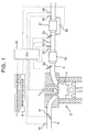
- FIG. 1 is a view that shows the schematic configuration of an internal combustion engine and intake and exhaust systems of the internal combustion engine according to the present embodiment.
- the internal combustion engine 1 shown in FIG. 1 is a compression-ignition internal combustion engine (diesel engine) that uses light oil as fuel.
- the internal combustion engine 1 may be a spark-ignition internal combustion engine that uses gasoline, or the like, as fuel.
- the internal combustion engine 1 includes a fuel injection valve 3 that injects fuel into a cylinder 2.
- the fuel injection valve 3 may be configured to inject fuel into an intake port.
- the internal combustion engine 1 is connected to an intake passage 4.
- An air flow meter 40 and an intake throttle valve 41 are provided in the intake passage 4.
- the air flow meter 40 outputs an electrical signal corresponding to the amount (mass) of intake air (air) flowing through the intake passage 4.
- the intake throttle valve 41 is arranged in the intake passage 4 at a portion downstream of the air flow meter 40.
- the intake throttle valve 41 adjusts the intake air amount of the internal combustion engine 1 by changing the passage sectional area of the intake passage 4.
- the internal combustion engine 1 is connected to an exhaust passage 5.
- An oxidation catalyst 50, an SCRF 51, a fuel addition valve 52 and a urea water addition valve 53 are provided in the exhaust passage 5 as an exhaust gas control system.
- the SCRF 51 is formed such that an SCR catalyst is supported on a wall flow filter made of a porous base material.
- the thus configured SCRF 51 has a PM collecting function and an NOx purification function.
- the PM collecting function is used to collect PM in exhaust gas.
- the NOx purification function is used to reduce NOx in exhaust gas by using ammonia as a reducing agent.
- the oxidation catalyst 50 is provided in the exhaust passage 5 at a portion upstream of the SCRF 51.
- the fuel addition valve 52 is provided in the exhaust passage 5 at a portion further upstream of the oxidation catalyst 50.
- the fuel addition valve 52 adds fuel into exhaust gas flowing through the exhaust passage 5.
- the urea water addition valve 53 is provided in the exhaust passage 5 at a portion downstream of the oxidation catalyst 50 and upstream of the SCRF 51.
- the urea water addition valve 53 adds urea water into exhaust gas flowing through the exhaust passage 5.
- urea water is added from the urea water addition valve 53 into exhaust gas, the urea water is supplied to the SCRF 51.
- ammonia produced by the hydrolysis of supplied urea adsorbs to the SCR catalyst. NOx in exhaust gas is reduced by using the ammonia adsorbed to the SCR catalyst as a reducing agent. That is, the NOx purification function of the SCRF 51 is exercised by supplying urea water from the urea water addition valve 53.
- An O 2 concentration sensor 54, an upstream temperature sensor 55 and an upstream NOx sensor 57 are provided in the exhaust passage 5 at a portion downstream of the oxidation catalyst 50 and upstream of the urea water addition valve 53.
- a downstream temperature sensor 56 and a downstream NOx sensor 58 are provided in the exhaust passage 5 at a portion downstream of the SCRF 51.
- the O 2 concentration sensor 54 outputs an electrical signal corresponding to the concentration of O 2 in exhaust gas.
- Each of the upstream temperature sensor 55 and the downstream temperature sensor 56 outputs an electrical signal corresponding to the temperature of exhaust gas.
- Each of the upstream NOx sensor 57 and the downstream NOx sensor 58 outputs an electrical signal corresponding to the concentration of NOx in exhaust gas.
- a differential pressure sensor 59 is provided in the exhaust passage 5. The differential pressure sensor 59 outputs an electrical signal corresponding to a filter differential pressure that is a pressure difference in exhaust gas between the upstream side and downstream side of the SCRF 51.
- An electronic control unit (ECU) 10 is provided in combination with the internal combustion engine 1.
- the ECU 10 is a unit that controls the operation state, and the like, of the internal combustion engine 1.
- Various sensors such as an accelerator position sensor 7 and a crank position sensor 8, are electrically connected to the ECU 10 in addition to the air flow meter 40, the O 2 concentration sensor 54, the upstream temperature sensor 55, the upstream NOx sensor 57, the downstream temperature sensor 56, the downstream NOx sensor 58 and the differential pressure sensor 59.
- the accelerator position sensor 7 is a sensor that outputs an electrical signal that correlates with the operation amount of an accelerator pedal (not shown) (accelerator operation amount).
- the crank position sensor 8 is a sensor that outputs an electrical signal that correlates with the rotation position of an engine output shaft (crankshaft) of the internal combustion engine 1. The output signals of these sensors are input to the ECU 10.
- Various devices such as the fuel injection valve 3, the intake throttle valve 41, the fuel addition valve 52 and the urea water addition valve 53, are electrically connected to the ECU 10.
- the ECU 10 controls the various devices on the basis of the output signals of the above-described sensors.
- the ECU 10 controls a urea water addition amount from the urea water addition valve 53 in order to keep an ammonia adsorption amount in the SCRF 51 (that is, the amount of ammonia adsorbed to the SCR catalyst) at a target adsorption amount.
- the target adsorption amount is a value determined in advance on the basis of an experiment, or the like, as a value at which it is possible to ensure a desired NOx purification ratio (the ratio of the amount of NOx that is reduced in the SCRF 51 to the amount of NOx that flows into the SCRF 51) in the SCRF 51 and it is possible to suppress the amount of ammonia that flows out from the SCRF 51 within an allowable range.
- the ECU 10 executes a filter regeneration process by adding fuel from the fuel addition valve 52 when an estimated amount of PM accumulated in the SCRF 51 has reached a predetermined threshold.
- the temperature of the SCRF 51 is raised by heat of oxidation that is generated when fuel added from the fuel addition valve 52 is oxidized in the oxidation catalyst 50.
- the ECU 10 controls a fuel addition amount from the fuel addition valve 52 in order to set the temperature of the SCRF 51 to a target temperature.
- the temperature of the SCRF 51 is estimated on the basis of the output value of the downstream temperature sensor 56.
- the target temperature is a value determined in advance on the basis of an experiment, or the like, as a temperature at which oxidation of PM is possible. As a result, PM that has accumulated in the SCRF 51 is burned and removed.
- the SCRF in which the SCR catalyst is supported on the filter is employed; however, the configuration of the filter and SCR catalyst is not limited to this configuration. That is, the filter and the SCR catalyst may be separately arranged in the exhaust passage at a portion downstream of the urea water addition valve. In this case, the filter and the SCR catalyst may be arranged in order from the upstream side or may be arranged in the reverse order.
- the differential pressure sensor is employed as means for acquiring the filter differential pressure; however, the configuration of a differential pressure acquisition device is not limited to this configuration. For example, pressure sensors may be respectively provided in the exhaust passage at a portion upstream of the filter and a portion downstream of the filter, and a filter differential pressure may be calculated from a difference between the output values of these two pressure sensors.
- the ECU 10 continuously estimates a first estimated amount that is an estimated amount of PM accumulated in the SCRF 51.
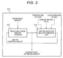
- FIG. 2 is a block diagram that shows the functions of a PM accumulation amount estimation unit 110 in the ECU 10.
- the PM accumulation amount estimation unit 110 is a functional unit for estimating the first estimated amount.
- the PM accumulation amount estimation unit 110 estimates a PM accumulation amount on the assumption that the SCRF 51 is in a normal state.
- the PM accumulation amount estimation unit 110 includes a PM accumulation amount counter 111 and a unit PM oxidation amount estimation unit 112.
- the amount of PM emitted from the internal combustion engine 1 per unit time (hereinafter, which may also be referred to as "unit PM emission amount") is input to the PM accumulation amount counter 111.
- the unit PM emission amount may be estimated on the basis of the operation state of the internal combustion engine 1.
- the PM accumulation amount counter 111 calculates a PM collection amount per unit time in the SCRF 51 (hereinafter, which may also be referred to as "unit PM collection amount”) by multiplying the input unit PM emission amount by a predetermined PM collection ratio (the ratio of the amount of PM collected by the SCRF 51 to the amount of PM that flows into the SCRF 51).
- the predetermined PM collection ratio may be determined on the basis of the flow rate of exhaust gas.
- the calculated unit PM collection amount is integrated.
- the temperature of the SCRF 51 In addition to the first estimated amount that is the current estimated PM accumulation amount in the SCRF 51, calculated by the PM accumulation amount counter 111, the temperature of the SCRF 51, the concentration of O 2 in exhaust gas flowing into the SCRF 51 (hereinafter, which may also be referred to as "inflow exhaust gas") and the concentration of NO 2 in inflow exhaust gas are input to the unit PM oxidation amount estimation unit 112.
- the temperature of the SCRF 51 may be estimated on the basis of the output value of the downstream temperature sensor 56.
- the concentration of O 2 in inflow exhaust gas is detected by the O 2 concentration sensor 54.
- the concentration of O 2 in inflow exhaust gas may be estimated on the basis of the air-fuel ratio of exhaust gas, the operation state of the internal combustion engine 1, or the like.
- the concentration of NO 2 in inflow exhaust gas may be estimated on the basis of the output value of the air flow meter 40, the output value of the upstream temperature sensor 55, the output value of the upstream NOx sensor 57, and the like.
- the amount of NOx in exhaust gas may be estimated on the basis of the flow rate of exhaust gas and the output value of the upstream NOx sensor 57.
- the flow rate of exhaust gas is estimated on the basis of the output value of the air flow meter 40.
- the ratio of NO 2 in inflow exhaust gas may be estimated on the basis of the temperature of the oxidation catalyst 50 and the flow rate of exhaust gas.
- the temperature of the oxidation catalyst 50 is estimated on the basis of the output value of the upstream temperature sensor 55.
- the concentration of NO 2 in inflow exhaust gas may be estimated on the basis of the amount of NOx in exhaust gas, the estimated ratio of NO 2 in the amount of NOx in inflow exhaust gas, and the like.
- the unit PM oxidation amount estimation unit 112 calculates a PM oxidation amount in the SCRF 51 per unit time (hereinafter, which may also be referred to as "unit PM oxidation amount") on the basis of the input current first estimated amount, the input temperature of the SCRF 51, the input concentration of O 2 in inflow exhaust gas and the input concentration of NO 2 in inflow exhaust gas.
- the calculated unit PM oxidation amount is input to the PM accumulation amount counter 111.
- the PM accumulation amount counter 111 calculates the current first estimated amount by subtracting the unit PM oxidation amount from the integrated PM collection amount calculated as described above.
- a determination differential pressure is set on the basis of the first estimated amount calculated by the PM accumulation amount estimation unit 110 as described above.
- the ECU 10 executes a malfunction diagnosis process for diagnosing whether there is a malfunction in the SCRF 51 by comparing an actual filter differential pressure, which is detected by the differential pressure sensor 59, with the determination differential pressure. If there occurs a malfunction in the SCRF 51, the filter differential pressure decreases as compared to when the SCRF 51 is in the normal state. Therefore, in the malfunction diagnosis process, when the actual filter differential pressure, which is detected by the differential pressure sensor 59, is smaller than the determination differential pressure, it is diagnosed that there is a malfunction in the SCRF 51. That is, the determination differential pressure is set as a lower limit value of the filter differential pressure in the case where the SCRF 51 is in the normal state.
- the PM accumulation amount estimation unit 110 is an example of a PM accumulation amount estimation unit.
- the method of estimating a first estimated amount by the PM accumulation amount estimation unit is not limited to the above-described method. Any known method may be employed as the method of estimating a first estimated amount as long as the estimation method uses a parameter other than the filter differential pressure.
- urea water added from the urea water addition valve 53 is supplied to the SCRF 51. Therefore, other than PM emitted from the internal combustion engine 1, a urea deposit may accumulate in the SCRF 51.
- a urea deposit that has once accumulated in the SCRF 51 vaporizes or becomes ammonia gas in a gaseous form to separate from the SCRF 51.
- the temperature at which a urea deposit vaporizes or the temperature at which a urea deposit becomes ammonia gas is lower than the oxidation temperature of PM. That is, even when the temperature of the SCRF 51 is lower than the oxidation temperature of PM, a urea deposit separates from the SCRF 51.
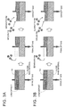
- FIG. 3A and FIG. 3B are a conceptual view that shows the behavior of PM at the time when a urea deposit separates from the SCRF 51.
- a urea deposit and PM may accumulate on the base material of the SCRF 51 so as to overlap with each other.
- the PM accumulated on the urea deposit so as to overlap with the urea deposit may also separate from the SCRF 51 accordingly without being oxidized.
- PM that has separated from the SCRF 51 is collected again by the SCRF 51.
- PM newly flowing into the SCRF 51 inflow PM
- PM accumulates again on the portion in the SCRF 51, from which the urea deposit and the PM have separated.
- FIG 4 is a time chart that shows changes in the temperature of the SCRF 51, changes in the amount of PM accumulated in the SCRF 51 and the amount of urea deposit accumulated in the SCRF 51, and changes in filter differential pressure.
- the line L1 indicates changes in the temperature of the SCRF 51.
- the line L2 indicates changes in first estimated amount that is estimated by the PM accumulation amount estimation unit 110 of the ECU 10.
- the line L3 indicates changes in the amount of urea deposit accumulated in the SCRF 51.
- the line L4 indicates changes in filter differential pressure corresponding to the first estimated amount.
- the line L5 indicates changes in actual filter differential pressure that is detected by the differential pressure sensor 59.
- the temperature of the SCRF 51 gradually rises with a lapse of time, and the temperature of the SCRF 51 becomes higher than or equal to a temperature Td at which the separation of a urea deposit occurs at time t0. Therefore, as indicated by the line L3, the amount of urea deposit accumulated in the SCRF 51 begins to decrease from time t0. At this time, as indicated by the line L2, the first estimated amount continues to increase after time t0. However, after time t0, when PM separates from the SCRF 51 with the separation of a urea deposit as shown in FIG. 4 , an actual PM accumulation amount in the SCRF 51 reduces.
- the actual filter differential pressure decreases from time t0 as indicated by the line L5.
- PM accumulates again on the portion of the SCRF 51, from which the urea deposit and the PM have separated, so the actual filter differential pressure once decreases and then increases as indicated by the line L5 in FIG. 4 .
- the actual filter differential pressure recovers to a value corresponding to the first estimated amount.
- the ECU 10 determines whether a predetermined condition is satisfied.
- the predetermined condition is set as a condition under which the amount of separated PM that separates from the SCRF 51 with the separation of a urea deposit can be larger than or equal to a predetermined separation amount.
- the predetermined separation amount is a threshold of the amount of separated PM at or above which it may be determined that the amount of decrease in filter differential pressure due to the separation of PM becomes larger than an allowable amount.
- a predetermined diagnosis prohibition period is provided.
- execution of the malfunction diagnosis process for the SCRF is prohibited.
- the diagnosis prohibition period is set so as to be longer than or equal to a period that is estimated to be minimally required from the beginning of a decrease in the filter differential pressure due to the separation of PM from the SCRF 51 to the recovery of the filter differential pressure as described above. Because such a diagnosis prohibition period is set, it is possible to avoid execution of the malfunction diagnosis process for the SCRF 51 in the state where there is a high possibility of occurrence of an erroneous diagnosis. Therefore, it is possible to reduce erroneous diagnosis in diagnosing a malfunction in the SCRF 51.
- the amount of separated PM at the time when PM separates from the SCRF 51 with the separation of a urea deposit correlates with the PM accumulation amount in the SCRF 51 and the temperature of the SCRF 51. Specifically, as the PM accumulation amount in the SCRF 51 increases, the PM accumulation amount, by which PM accumulates so as to overlap with a urea deposit as indicated by FIG. 3A and FIG. 3B , also increases. Therefore, as the PM accumulation amount in the SCRF 51 increases, the amount of separated PM that separates from the SCRF 51 with the separation of a urea deposit increases. As the temperature of the SCRF 51 rises, the separation of a urea deposit is facilitated. Therefore, as the temperature of the SCRF 51 rises, the amount of separated PM that separates from the SCRF 51 with the separation of a urea deposit increases.
- the predetermined condition is defined on the basis of the first estimated amount and the temperature of the SCRF 51. That is, in the present embodiment, the predetermined condition is defined as a condition that the temperature of the SCRF 51 is higher than or equal to a predetermined temperature and the first estimated amount is larger than or equal to a first predetermined amount.
- the predetermined temperature and the first predetermined amount at this time are determined by the map shown in FIG. 5 .
- the abscissa axis represents the temperature of the SCRF 51
- the ordinate axis represents the first estimated amount.
- the line L6 indicates the boundary of a region in which the predetermined condition is satisfied. As shown in FIG.
- the predetermined condition is satisfied even when the temperature of the SCRF 51 is a lower temperature. As the temperature of the SCRF 51 rises, the predetermined condition is satisfied even when the first estimated amount is a smaller value. That is, the line L6 in FIG. 5 indicates the correlation between the first estimated amount and the predetermined temperature, and the predetermined temperature is set to a lower temperature as the first estimated amount increases. The line L6 in FIG. 5 indicates the correlation between the temperature of the SCRF 51 and the first predetermined amount, and the first predetermined amount is set to a smaller value as the temperature of the SCRF 51 rises.
- the diagnosis prohibition period is set to a longer period as compared to when it is estimated that the amount of separated PM is small.
- the length of the diagnosis prohibition period is set on the basis of the temperature of the SCRF 51 and the first estimated amount at the point in time at which the ECU 10 determines that the predetermined condition is satisfied.
- FIG. 6 is a map that shows the correlation between both the temperature of the SCRF 51 and the first estimated amount at the point in time, at which the ECU 10 determines that the predetermined condition is satisfied, and the length of the diagnosis prohibition period.
- each line L7 indicates the correlation between the temperature of the SCRF 51 at the point in time, at which it is determined that the predetermined condition is satisfied, and the length of the diagnosis prohibition period.
- FIG. 6 is a map that shows the correlation between both the temperature of the SCRF 51 and the first estimated amount at the point in time, at which the ECU 10 determines that the predetermined condition is satisfied, and the length of the diagnosis prohibition period.
- the correlation between the temperature of the SCRF 51 and the length of the diagnosis prohibition period is set in response to the first estimated amount at the point in time at which it is determined that the predetermined condition is satisfied, is set.
- the temperature of the SCRF 51 at the point in time, at which the ECU 10 determines that the predetermined condition is satisfied rises, the amount of separated PM increases.
- the first estimated amount at the point in time, at which the ECU 10 determines that the predetermined condition is satisfied increases, the amount of separated PM increases. Therefore, as shown in FIG. 6 , as the temperature of the SCRF 51 rises or as the first estimated amount increases, the diagnosis prohibition period is set to a longer period.
- FIG 7 is a flowchart that shows the flow of setting the diagnosis prohibition period according to the present embodiment.
- the flow is stored in the ECU 10 in advance, and is repeatedly executed by the ECU 10 at predetermined intervals during operation of the internal combustion engine 1.
- S101 it is determined whether it is currently in the diagnosis prohibition period.
- execution of the flow is once ended.
- a predetermined temperature Tf0 is subsequently set in S102 on the basis of a current first estimated amount Qpm that is calculated by the PM accumulation amount estimation unit 110.
- a first predetermined amount QpmO is set on the basis of the current temperature Tf of the SCRF 51, which is estimated on the basis of the output value of the downstream temperature sensor 56.
- the predetermined temperature Tf0 and the first predetermined amount Qpm0 are set by using the map shown in FIG. 5 .
- the length Lp of the diagnosis prohibition period is calculated on the basis of the current temperature Tf of the SCRF 51 and the current first estimated amount Qpm.
- the length Lp of the diagnosis prohibition period is calculated by using the map shown in FIG. 6 .
- the period of the length Lp calculated in S106 from the current time that is, the point in time at which it is determined that the predetermined condition is satisfied, is set as the diagnosis prohibition period.
- FIG. 8 is a flowchart that shows the flow of diagnosing a malfunction in the SCRF 51 according to the present embodiment.
- the flow is stored in the ECU 10 in advance, and is repeatedly executed by the ECU 10 at predetermined intervals during operation of the internal combustion engine 1.
- the malfunction diagnosis execution condition may include, for example, a condition that the operation state of the internal combustion engine 1 is steady operation and a predetermined period has elapsed from execution of the last malfunction diagnosis process, a condition that a predetermined period has elapsed from the start of the current operation of the internal combustion engine 1, and the like.
- the malfunction diagnosis execution condition is set such that the necessary and sufficient frequency of execution of the malfunction diagnosis process is ensured.
- a determination differential pressure Dfp0 is subsequently set in S203 on the basis of the current first estimated amount Qpm that is calculated by the PM accumulation amount estimation unit 110.
- the correlation between the first estimated amount Qpm and the determination differential pressure Dfp0 is determined in advance on the basis of an experiment, or the like, and the correlation therebetween is stored in the ECU 10 as a map. In this map, as the first estimated amount Qpm increases, the determination differential pressure Dfp0 becomes a larger value.
- the determination differential pressure Dfp0 is set by using the map.
- the malfunction diagnosis process is executed in S204. That is, in S204, it is determined whether an actual filter differential pressure Dfp that is detected by the differential pressure sensor 59 is smaller than the determination differential pressure Dfp0 set in S203. When affirmative determination is made in S204, it is subsequently determined in S205 that there is a malfunction in the SCRF 51. On the other hand, when negative determination is made in S204, it is subsequently determined in S206 that the SCRF 51 is in the normal state.
- the malfunction diagnosis execution condition may include a condition that it is not in the diagnosis prohibition period.
- the predetermined temperature and the first predetermined amount that define the predetermined condition as shown in FIG. 5 , the predetermined temperature is continuously changed in response to the first estimated amount, and the first predetermined amount is continuously changed in response to the temperature of the SCRF 51.
- the predetermined temperature may be changed for the first estimated amount in a stepwise manner.
- the first predetermined amount may be changed for the temperature of the SCRF 51 in a stepwise manner.
- One of the predetermined temperature and the first predetermined amount may be set to a predetermined constant value.
- the predetermined condition as a further appropriate condition by setting the predetermined temperature to a value commensurate with the first estimated amount and setting the first predetermined amount to a value commensurate with the temperature of the SCRF 51. That is, it is possible to reduce an unnecessary diagnosis prohibition period.
- the length of the diagnosis prohibition period is set on the basis of the temperature of the SCRF 51 and the first estimated amount at the point in time at which the ECU 10 determines that the predetermined condition is satisfied.
- the length of the diagnosis prohibition period may be set to a predetermined constant length.
- the length of the diagnosis prohibition period may be set on the basis of one of the temperature of the SCRF 51 and the first estimated amount at the point in time at which the ECU 10 determines that the predetermined condition is satisfied.
- the length of the diagnosis prohibition period may be changed in a stepwise manner for the temperature of the SCRF 51 or the first estimated amount at the point in time at which the ECU 10 determines that the predetermined condition is satisfied.
- the filter differential pressure that has decreased because of the separation of PM from the SCRF 51 recovers when PM accumulates again in the SCRF 51. Therefore, the degree of recovery at the time when the filter differential pressure once decreases because of the separation of PM from the SCRF 51 and then recovers correlates with the amount of increase in PM accumulation amount in the SCRF 51 after PM has separated from the SCRF 51.
- the diagnosis prohibition period is set as a period that is taken until the amount of increase in first estimated amount from the point in time, at which the ECU 10 determines that the predetermined condition is satisfied, reaches a predetermined increasing amount.
- FIG. 9 is a map that shows the correlation between both the temperature of the SCRF 51 and the first estimated amount at the point in time, at which the ECU 10 determines that the predetermined condition is satisfied, and the predetermined increasing amount.
- each line L8 indicates the correlation between the temperature of the SCRF 51 at the point in time, at which it is determined that the predetermined condition is satisfied, and the predetermined increasing amount.
- the correlation between the temperature of the SCRF 51 and the predetermined increasing amount, corresponding to the first estimated amount at the point in time at which it is determined that the predetermined condition is satisfied is set.
- the predetermined increasing amount is set to a larger value.
- the predetermined increasing amount is set to a larger value as compared to when it is estimated that the amount of separated PM is small. Therefore, according to the present alternative embodiment, it is possible to set the diagnosis prohibition period to a further appropriate period.
- the predetermined increasing amount is calculated in S106 on the basis of the current temperature Tf of the SCRF 51 and the current first estimated amount. At this time, the predetermined increasing amount is calculated by using the map shown in FIG. 9 . In S107, the period during which the amount of increase in first estimated amount from the current point in time, that is, the point in time at which it is determined that the predetermined condition is satisfied, reaches the predetermined increasing amount calculated in S106 is set as the diagnosis prohibition period.
- the predetermined increasing amount may be set to a predetermined constant amount.
- the predetermined increasing amount may be set on the basis of one of the temperature of the SCRF 51 and the first estimated amount at the point in time at which the ECU 10 determines that the predetermined condition is satisfied.
- the predetermined increasing amount may be changed in a stepwise manner for the temperature of the SCRF 51 or the first estimated amount at the point in time at which the ECU 10 determines that the predetermined condition is satisfied.
- the PM accumulation amount estimation unit 110 in the ECU 10 continuously estimates the first estimated amount.
- the ECU 10 continuously estimates a second estimated amount that is an estimated amount of urea deposit accumulated in the SCRF 51.
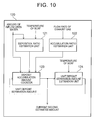
- FIG. 10 is a block diagram that shows the functions of a deposit accumulation amount estimation unit 120 in the ECU 10.
- the deposit accumulation amount estimation unit 120 is a functional unit for estimating the second estimated amount.
- the deposit accumulation amount estimation unit 120 includes a deposition ratio estimation unit 121, an accumulation ratio estimation unit 122, a deposit accumulation amount counter 123 and a unit deposit separation amount estimation unit 124.
- the amount of urea water flowing into the SCRF 51 and the temperature of the SCRF 51 are input to the deposition ratio estimation unit 121.
- the amount of urea water flowing into the SCRF 51 is equivalent to the urea water addition amount from the urea water addition valve 53.
- the flow rate of urea water that flows out from the SCR catalyst without being hydrolyzed in the SCR catalyst is input to the deposition ratio estimation unit 121 as the amount of urea water flowing into the filter.
- the deposition ratio estimation unit 121 calculates a deposition ratio (the ratio of the amount of urea deposit produced to the amount of urea water flowing into the SCRF 51) on the basis of the input amount of urea water flowing into the SCRF 51 and the input temperature of the SCRF 51.
- a deposition ratio the ratio of the amount of urea deposit produced to the amount of urea water flowing into the SCRF 51
- the flow rate of exhaust gas is input to the accumulation ratio estimation unit 122.
- the accumulation ratio estimation unit 122 calculates an accumulation ratio (the ratio of a urea deposit that accumulates in the SCRF 51 to the amount of urea deposit produced) on the basis of the input flow rate of exhaust gas. As the flow rate of exhaust gas decreases, a urea deposit is more easy to accumulate in the SCRF 51. Therefore, as the flow rate of exhaust gas decreases, the accumulation ratio increases.
- the amount of urea water flowing into the SCRF 51, the deposition ratio calculated by the deposition ratio estimation unit 121 and the accumulation ratio calculated by the accumulation ratio estimation unit 122 are input to the deposit accumulation amount counter 123.
- the deposit accumulation amount counter 123 calculates the amount of urea deposit accumulated per unit time (hereinafter, which may also be referred to as "unit deposit accumulation amount") in the SCRF 51 by multiplying the amount of urea water flowing into the SCRF 51 by the deposition ratio and the accumulation ratio. In addition, the calculated unit deposit accumulation amount is integrated.
- the temperature of the SCRF 51 is input to the unit deposit separation amount estimation unit 124.
- the unit deposit separation amount estimation unit 124 calculates a deposit separation amount per unit time (hereinafter, which may also be referred to as "unit deposit separation amount") in the SCRF 51 on the basis of the input current deposit accumulation amount in the SCRF 51 and the current temperature of the SCRF 51. Then, the calculated unit deposit separation amount is input to the deposit accumulation amount counter 123.
- the deposit accumulation amount counter 123 calculates the current second estimated amount by subtracting the unit deposit separation amount from the integrated value of the unit deposit accumulation amount calculated as described above.
- the amount of separated PM at the time when PM separates from the SCRF 51 with the separation of a urea deposit correlates with the amount of urea deposit accumulated in the SCRF 51. That is, under the condition that the temperature of the SCRF 51 is the same, the unit deposit separation amount increases as the amount of urea deposit accumulated in the SCRF 51 increases. As the amount of separated urea deposit increases, the amount of separated PM that separates from the SCRF 51 as a result of the separation of the urea deposit increases. Therefore, as the amount of separated urea deposit in the SCRF 51 increases, the amount of separated PM that separates from the SCRF 51 as a result of the separation of the urea deposit increases.
- the predetermined condition is defined on the basis of the temperature of the SCRF 51 and the second estimated amount. That is, in the present embodiment, the predetermined condition is defined as a condition that the temperature of the SCRF 51 is higher than or equal to a predetermined temperature and the second estimated amount is larger than or equal to a second predetermined amount.
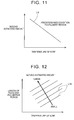
- the predetermined temperature and the second predetermined amount at this time are determined by using the map shown in FIG. 11 .
- the abscissa axis represents the temperature of the SCRF 51
- the ordinate axis represents the second estimated amount.
- the line L9 indicates the boundary of a region in which the predetermined condition is satisfied. As shown in FIG.
- the predetermined condition is satisfied even when the temperature of the SCRF 51 is a lower temperature. As the temperature of the SCRF 51 rises, the predetermined condition is satisfied even when the second estimated amount is a smaller amount. That is, the line L9 shown in FIG. 11 indicates the correlation between the second estimated amount and the predetermined temperature, and the predetermined temperature is set to a lower temperature as the second estimated amount increases. The line L9 in FIG. 11 indicates the correlation between the temperature of the SCRF 51 and the second predetermined amount, and the second predetermined amount is set to a smaller value as the temperature of the SCRF 51 rises.
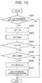
- the length of the diagnosis prohibition period is set on the basis of the temperature of the SCRF 51 and the second estimated amount at the point in time at which the ECU 10 determines that the above-described predetermined condition is satisfied.
- FIG. 12 is a map that shows the correlation between both the temperature of the SCRF 51 and the second estimated amount at the point in time, at which the ECU 10 determines that the predetermined condition is satisfied, and the length of the diagnosis prohibition period.
- each line L10 indicates the correlation between the temperature of the SCRF 51 at the point in time, at which it is determined that the predetermined condition is satisfied, and the length of the diagnosis prohibition period.
- FIG. 12 is a map that shows the correlation between both the temperature of the SCRF 51 and the second estimated amount at the point in time, at which the ECU 10 determines that the predetermined condition is satisfied, and the length of the diagnosis prohibition period.
- the correlation between the temperature of the SCRF 51 and the length of the diagnosis prohibition period is set in response to the second estimated amount at the point in time at which it is determined that the predetermined condition is satisfied, is set.
- the amount of separated PM increases as the temperature of the SCRF 51 at the point in time, at which the ECU 10 determines that the predetermined condition is satisfied.
- the diagnosis prohibition period is set to a longer period.
- FIG. 13 is a flowchart that shows the flow of setting the diagnosis prohibition period according to the present embodiment.
- S101 and S107 are steps in which similar processes to those of S101 and S107 in the flow shown in FIG. 7 are executed. Therefore, the description of these steps is omitted.
- the flow is stored in the ECU 10 in advance, and is repeatedly executed by the ECU 10 at predetermined intervals during operation of the internal combustion engine 1.
- the predetermined temperature Tf0 is subsequently set in S302 on the basis of a current second estimated amount Qde that is calculated by the deposit accumulation amount estimation unit 120.
- a second predetermined amount Qde0 is set on the basis of the current temperature Tf of the SCRF 51, which is estimated on the basis of the output value of the downstream temperature sensor 56.
- the predetermined temperature Tf0 and the second predetermined amount Qde0 are set by using the map shown in FIG. 11 .
- the length Lp of the diagnosis prohibition period is calculated on the basis of the current temperature Tf of the SCRF 51 and the current second estimated amount Qde.
- the length Lp of the diagnosis prohibition period is calculated by using the map shown in FIG. 12 .
- the predetermined temperature is continuously changed in response to the second estimated amount.
- the second predetermined amount is continuously changed in response to the temperature of the SCRF 51.
- the predetermined temperature may be changed for the second estimated amount in a stepwise manner.
- the second predetermined amount may be changed for the temperature of the SCRF 51 in a stepwise manner.
- One of the predetermined temperature and the second predetermined amount may be set to a predetermined constant value.
- the predetermined condition as a further appropriate condition by setting the predetermined temperature to a value commensurate with the second estimated amount and setting the second predetermined amount to a value commensurate with the temperature of the SCRF 51. That is, it is possible to reduce an unnecessary diagnosis prohibition period.
- the predetermined condition may be defined on the basis of the first estimated amount, the temperature of the SCRF 51 and the second estimated amount.
- the predetermined condition when the predetermined condition is defined as a condition that the temperature of the SCRF 51 is higher than or equal to the predetermined temperature and the first estimated amount is larger than or equal to the first predetermined amount, the predetermined temperature may be set to a lower temperature as the first estimated amount increases or as the second estimated amount increases. In this case, the first predetermined amount may be set to a smaller value as the temperature of the SCRF 51 rises or as the second estimated amount increases.
- the predetermined condition when the predetermined condition is defined as a condition that the temperature of the SCRF 51 is higher than or equal to the predetermined temperature and the second estimated amount is larger than or equal to the second predetermined amount as well, the predetermined temperature may be set to a lower temperature as the first estimated amount increases or as the second estimated amount increases. In this case, the second predetermined amount may be set to a smaller value as the temperature of the SCRF 51 rises or as the first estimated amount increases. In this way, by defining the predetermined condition on the basis of the first estimated amount, the temperature of the SCRF 51 and the second estimated amount, it is possible to reduce an unnecessary diagnosis prohibition period as much as possible.
- the length of the diagnosis prohibition period may be set on the basis of one of the temperature of the SCRF 51 and the second estimated amount at the point in time at which the ECU 10 determines that the predetermined condition is satisfied.
- the length of the diagnosis prohibition period may be changed in a stepwise manner for the temperature of the SCRF 51 or the second estimated amount at the point in time at which the ECU 10 determines that the predetermined condition is satisfied.
- the length of the diagnosis prohibition period may be set on the basis of the first estimated amount, the temperature of the SCRF 51 and the second estimated amount at the point in time at which the ECU 10 determines that the predetermined condition is satisfied.
- the diagnosis prohibition period is set as a period that is taken until the amount of increase in first estimated amount from the point in time at which the ECU 10 determines that the predetermined condition is satisfied reaches a predetermined increasing amount.
- the predetermined increasing amount is set to a larger value.
- the predetermined increasing amount is set to a larger value as compared to when it is estimated that the amount of separated PM is small. Therefore, according to the present alternative embodiment, it is possible to set the diagnosis prohibition period to a further appropriate period.
- the predetermined increasing amount may be set on the basis of one of the temperature of the SCRF 51 and the second estimated amount at the point in time at which the ECU 10 determines that the predetermined condition is satisfied.
- the predetermined increasing amount may be changed in a stepwise manner for the temperature of the SCRF 51 or the second estimated amount at the point in time at which the ECU 10 determines that the predetermined condition is satisfied.
- the predetermined increasing amount may be set in consideration of the first estimated amount at the point in time at which the ECU 10 determines that the predetermined condition is satisfied. That is, in the present alternative embodiment as well, the predetermined increasing amount may be set to a larger value as the first estimated amount at the point in time, at which the ECU 10 determines that the predetermined condition is satisfied, increases.
- the predetermined condition is defined on the basis of the temperature of the SCRF 51 and the first estimated amount.
- the ECU 10 determines whether the predetermined condition is satisfied.
- a predetermined correction period for correcting a determination threshold that is used in the malfunction diagnosis process for the SCRF is provided instead of the predetermined diagnosis prohibition period.
- the length of the correction period is set to a length longer than or equal to a period that is estimated to be minimally required from the beginning of a decrease in the filter differential pressure due to the separation of PM from the SCRF 51 to the recovery of the filter differential pressure.
- the length of the correction period is set by a similar method to the method for setting the length of the diagnosis prohibition period according to the first embodiment.
- the determination differential pressure for the first estimated amount is corrected to a smaller value as compared to the case where it is determined that the predetermined condition is not satisfied, and then the malfunction diagnosis process for the SCRF is executed.
- the filter differential pressure has decreased because of the separation of PM from the SCRF 51 with the separation of a urea deposit, it is more difficult to be diagnosed that there is a malfunction in the SCRF 51 as compared to the case where the malfunction diagnosis process is executed without any correction. Therefore, according to the present embodiment as well, it is possible to reduce erroneous diagnosis in diagnosing a malfunction in the SCRF.
- the determination differential pressure that is calculated by a similar method to that of the first embodiment on the basis of the first estimated amount is referred to as "reference determination differential pressure".
- a corrected determination differential pressure is calculated by multiplying the reference determination differential pressure by a correction coefficient x, and the malfunction diagnosis process for the SCRF is executed by using the corrected determination differential pressure.
- the correction coefficient x is a positive value smaller than 1.
- the correction coefficient x is set on the basis of the temperature of the SCRF 51 and the first estimated amount at the point in time at which the ECU 10 determines that the predetermined condition is satisfied.
- FIG. 14 is a map that shows the correlation between both the temperature of the SCRF 51 and the first estimated amount at the point in time, at which the ECU 10 determines that the predetermined condition is satisfied, and the correction coefficient x.
- each line L11 indicates the correlation between the temperature of the SCRF 51 at the point in time, at which the ECU 10 determines that the predetermined condition is satisfied, and the correction coefficient x.
- FIG. 14 is a map that shows the correlation between both the temperature of the SCRF 51 and the first estimated amount at the point in time, at which the ECU 10 determines that the predetermined condition is satisfied.
- the correlation between the temperature of the SCRF 51 and the correction coefficient x, corresponding to the first estimated amount at the point in time at which the ECU 10 determines that the predetermined condition is satisfied, is set.
- the correction coefficient x is set to a smaller value as the temperature of the SCRF 51 rises or as the first estimated amount increases.
- the corrected determination differential pressure becomes a smaller value with respect to the reference determination differential pressure as the temperature of the SCRF 51 rises or as the first estimated amount increases. Therefore, the corrected determination differential pressure becomes a smaller value with respect to the reference determination differential pressure as the amount of separated PM increases.
- FIG. 15 is a flowchart that shows the flow of setting the correction period according to the present embodiment.
- S102 to S105 are steps in which similar processes to those of S102 to S105 in the flow shown in FIG. 7 are executed. Therefore, the description of these steps is omitted.
- the flow is stored in the ECU 10 in advance, and is repeatedly executed by the ECU 10 at predetermined intervals during operation of the internal combustion engine 1.
- the length La of the correction period is calculated on the basis of the current temperature Tf of the SCRF 51 and the current first estimated amount Qpm.
- the length La of the correction period is calculated by a similar method to the method of calculating the length Lp of the diagnosis prohibition period in S106 of the flow shown in FIG. 7 . Therefore, the length La of the correction period is calculated as a longer period as the current temperature of the SCRF 51 rises or as the current first estimated amount increases.
- the correction coefficient x is set on the basis of the current temperature Tf of the SCRF 51 and the current first estimated amount Qpm.
- the correction coefficient x is set by using the map shown in FIG. 14 .
- the correction coefficient x is stored in the ECU 10.
- the period of the length La calculated in S406 from the current point in time, that is, the point in time at which it is determined that the predetermined condition is satisfied, is set as the correction period.
- FIG. 16 is a flowchart that shows the flow of diagnosing a malfunction in the SCRF according to the present embodiment.
- S201, S205 and S206 are steps in which similar processes to those of S201, S205 and S206 in the flow shown in FIG. 8 are executed. Therefore, the description of these steps is omitted.
- the flow is stored in the ECU 10 in advance, and is repeatedly executed by the ECU 10 at predetermined intervals during operation of the internal combustion engine 1.
- the reference determination differential pressure Dfp0 is set in S502 on the basis of a current first estimated amount Qpm that is calculated by the PM accumulation amount estimation unit 110.
- the reference determination differential pressure Dfp0 is set by using a similar map to the map that is used at the time when the determination differential pressure is set in S203 of the flow shown in FIG. 8 .
- the reference determination differential pressure Dfp0 calculated in S502 is subsequently set in S504 as the determination differential pressure.
- the malfunction diagnosis process is executed in S505.
- affirmative determination is made in S505
- a corrected determination differential pressure Dfp1 is subsequently calculated in S506 by multiplying the reference determination differential pressure Dfp0 calculated in S502 by the correction coefficient x that is set in S407 of the flow shown in FIG. 15 and stored in the ECU 10. Subsequently, in S507, the corrected determination differential pressure Dfp1 calculated in S506 is set as the determination differential pressure. Subsequently, in S508, the malfunction diagnosis process is executed. In S508, it is determined whether the actual filter differential pressure Dfp that is detected by the differential pressure sensor 59 is smaller than the corrected determination differential pressure Dfp1 set in S507 as the determination differential pressure. When affirmative determination is made in S508, it is subsequently determined in S205 that there is a malfunction in the SCRF 51. On the other hand, when negative determination is made in S508, it is subsequently determined in S206 that the SCRF 51 is in the normal state.
- the length of the correction period is set on the basis of the temperature of the SCRF 51 and the first estimated amount at the point in time at which the ECU 10 determines that the predetermined condition is satisfied.
- the length of the correction period may be set to a predetermined constant length.
- the length of the correction period may be set on the basis of one of the temperature of the SCRF 51 and the first estimated amount at the point in time at which the ECU 10 determines that the predetermined condition is satisfied.
- the length of the correction period may be changed in a stepwise manner for the temperature of the SCRF 51 or the first estimated amount at the point in time at which the ECU 10 determines that the predetermined condition is satisfied.
- the correction coefficient x is set on the basis of the temperature of the SCRF 51 and the first estimated amount at the point in time at which the ECU 10 determines that the predetermined condition is satisfied.
- the correction coefficient x may be set to a predetermined constant value.
- the correction coefficient x may be set on the basis of one of the temperature of the SCRF 51 and the first estimated amount at the point in time at which the ECU 10 determines that the predetermined condition is satisfied.
- the correction coefficient x may be changed in a stepwise manner for the temperature of the SCRF 51 or the first estimated amount at the point in time at which the ECU 10 determines that the predetermined condition is satisfied.
- the ECU 10 includes the deposit accumulation amount estimation unit 120.
- the predetermined condition is defined on the basis of the temperature of the SCRF 51 and the second estimated amount. That is, in the present alternative embodiment, the predetermined condition is defined as a condition that the temperature of the SCRF 51 is higher than or equal to a predetermined temperature and the second estimated amount is larger than or equal to a second predetermined amount.
- the length of the correction period is set by a similar method to the method for setting the length of the diagnosis prohibition period according to the second embodiment. That is, in the present alternative embodiment, the length of the correction period is set on the basis of the temperature of the SCRF 51 and the second estimated amount at the point in time at which the ECU 10 determines that the predetermined condition is satisfied.
- the correction coefficient x that is used to calculate the corrected determination differential pressure in the correction period is set on the basis of the temperature of the SCRF 51 and the second estimated amount at the point in time at which the ECU 10 determines that the predetermined condition is satisfied.
- FIG. 17 is a map that shows the correlation between both the temperature of the SCRF 51 and the second estimated amount at the point in time, at which the ECU 10 determines that the predetermined condition is satisfied, and the correction coefficient x.
- each line L12 indicates the correlation between the temperature of the SCRF 51 at the point in time, at which the ECU 10 determines that the predetermined condition is satisfied, and the correction coefficient x.
- FIG. 17 is a map that shows the correlation between both the temperature of the SCRF 51 and the second estimated amount at the point in time, at which the ECU 10 determines that the predetermined condition is satisfied.
- the correlation between the temperature of the SCRF 51 and the correction coefficient x, corresponding to the second estimated amount at the point in time at which it is determined that the predetermined condition is satisfied, is set.
- the correction coefficient x is set to a smaller value as the temperature of the SCRF 51 rises or as the second estimated amount increases.
- the corrected determination differential pressure becomes a smaller value with respect to the reference determination differential pressure as the temperature of the SCRF 51 rises or as the second estimated amount increases. Therefore, the corrected determination differential pressure becomes a smaller value with respect to the reference determination differential pressure as the amount of separated PM increases.
- the length of the correction period may be set on the basis of one of the temperature of the SCRF 51 and the second estimated amount at the point in time at which the ECU 10 determines that the predetermined condition is satisfied.
- the length of the correction period may be changed in a stepwise manner for the temperature of the SCRF 51 or the second estimated amount at the point in time at which the ECU 10 determines that the predetermined condition is satisfied.
- the length of the correction period may be set on the basis of the first estimated amount, the temperature of the SCRF 51 and the second estimated amount at the point in time at which the ECU 10 determines that the predetermined condition is satisfied.
- the correction coefficient x may be set on the basis of one of the temperature of the SCRF 51 and the second estimated amount at the point in time at which the ECU 10 determines that the predetermined condition is satisfied.
- the correction coefficient x may be changed in a stepwise manner for the temperature of the SCRF 51 or the second estimated amount at the point in time at which the ECU 10 determines that the predetermined condition is satisfied.
- the correction coefficient x may be set in consideration of the first estimated amount at the point in time at which the ECU 10 determines that the predetermined condition is satisfied.
- the correction coefficient x may be set on the basis of the first estimated amount, the temperature of the SCRF 51 and the second estimated amount at the point in time at which the ECU 10 determines that the predetermined condition is satisfied.
- a corrected filter differential pressure is calculated by multiplying the actual filter differential pressure, which is detected by the differential pressure sensor 59, by a correction coefficient y, and then the malfunction diagnosis process for the SCRF is executed by using the corrected filter differential pressure.
- the correction coefficient y is a value larger than 1.
- the correction coefficient y is set such that the corrected filter differential pressure becomes a larger value with respect to the actual filter differential pressure, as compared to when it is estimated that the amount of separated PM is small.
- the correction coefficient y is set on the basis of the temperature of the SCRF 51 and the first estimated amount at the point in time at which the ECU 10 determines that the predetermined condition is satisfied.
- FIG. 18 is a map that shows the correlation between both the temperature of the SCRF 51 and the first estimated amount at the point in time, at which the ECU 10 determines that the predetermined condition is satisfied, and the correction coefficient y.
- each line L13 indicates the correlation between the temperature of the SCRF 51 at the point in time, at which the ECU 10 determines that the predetermined condition is satisfied, and the correction coefficient y.
- FIG. 18 is a map that shows the correlation between both the temperature of the SCRF 51 and the first estimated amount at the point in time, at which the ECU 10 determines that the predetermined condition is satisfied.
- the correlation between the temperature of the SCRF 51 and the correction coefficient y, corresponding to the first estimated amount at the point in time at which the ECU 10 determines that the predetermined condition is satisfied, is set.
- the correction coefficient y is set to a larger value as the temperature of the SCRF 51 rises or as the first estimated amount increases.
- the corrected filter differential pressure becomes a larger value with respect to the actual filter differential pressure as the temperature of the SCRF 51 rises or as the first estimated amount increases. Therefore, as the amount of separated PM increases, the corrected filter differential pressure becomes a larger value with respect to the actual filter differential pressure.
- the correction coefficient y may be set to a predetermined constant value. However, as described above, it is possible to set the corrected filter differential pressure to a further appropriate value by setting the correction coefficient y on the basis of the temperature of the SCRF 51 and the first estimated amount.
- the correction coefficient y may be set on the basis of one of the temperature of the SCRF 51 and the first estimated amount at the point in time at which the ECU 10 determines that the predetermined condition is satisfied.
- the correction coefficient y may be changed in a stepwise manner for the temperature of the SCRF 51 or the first estimated amount at the point in time at which the ECU 10 determines that the predetermined condition is satisfied.
- FIG. 19 is a map that shows the correlation between both the temperature of the SCRF 51 and the second estimated amount at the point in time, at which the ECU 10 determines that the predetermined condition is satisfied, and the correction coefficient y.
- each line L14 indicates the correlation between the temperature of the SCRF 51 at the point in time, at which the ECU 10 determines that the predetermined condition is satisfied, and the correction coefficient y.
- the correlation between the temperature of the SCRF 51 and the correction coefficient y, corresponding to the second estimated amount at the point in time at which it is determined that the predetermined condition is satisfied, is set.
- the correction coefficient y is set to a smaller value as the temperature of the SCRF 51 rises or as the second estimated amount increases.
- the corrected filter differential pressure becomes a larger value with respect to the actual filter differential pressure as the temperature of the SCRF 51 rises or as the second estimated amount increases. Therefore, as the amount of separated PM increases, the corrected filter differential pressure becomes a larger value with respect to the actual filter differential pressure.
- the correction coefficient y may be set on the basis of one of the temperature of the SCRF 51 and the second estimated amount at the point in time at which the ECU 10 determines that the predetermined condition is satisfied.
- the correction coefficient y may be changed in a stepwise manner for the temperature of the SCRF 51 or the second estimated amount at the point in time at which the ECU 10 determines that the predetermined condition is satisfied.
- the correction coefficient y may be set on the basis of the first estimated amount, the temperature of the SCRF 51 and the second estimated amount at the point in time at which the ECU 10 determines that the predetermined condition is satisfied.
- the correction period is set as a period that is taken until the amount of increase in first estimated amount from the point in time at which the ECU 10 determines that the predetermined condition is satisfied reaches a predetermined increasing amount.
- the predetermined increasing amount is set to a larger value.
- the predetermined increasing amount is set to a larger value as compared to when it is estimated that the amount of separated PM is small. Therefore, according to the present alternative embodiment, it is possible to set the correction period to a further appropriate period.
- the predetermined increasing amount may be changed in a stepwise manner for the temperature of the SCRF 51, the first estimated amount or the second estimated amount at the point in time at which the ECU 10 determines that the predetermined condition is satisfied.
- the PM accumulation amount estimation unit 110 in the ECU 10 continuously estimates the first estimated amount.
- the deposit accumulation amount estimation unit 120 in the ECU 10 continuously calculates the second estimated amount.
- the predetermined condition is defined on the basis of at least any one of the temperature of the SCRF 51, the first estimated amount or the second estimated amount. In the present embodiment, when the ECU 10 determines that the predetermined condition is satisfied, execution of the malfunction diagnosis process for the SCRF 51 is prohibited until the ECU 10 determines that the predetermined condition is satisfied.
- execution of the malfunction diagnosis process for the SCRF 51 is prohibited also until an additional period elapses from the point in time at which the ECU 10 determines that the predetermined condition is not satisfied. That is, in the present embodiment, a period obtained by adding the additional period to the period from when the ECU 10 determines that the predetermined condition is satisfied to when the ECU 10 determines that the predetermined condition is not satisfied, as the diagnosis prohibition period.
- the ECU 10 calculates an estimated PM separation amount that is the estimated amount of separated PM in the period from when it is determined that the predetermined condition is satisfied to when the predetermined condition is not satisfied. Specifically, during the period in which the predetermined condition is satisfied, the amount of separated PM per unit time (hereinafter, which may also be referred to as "unit PM separation amount") is calculated on the basis of the temperature of the SCRF 51, the first estimated amount that is calculated by the PM accumulation amount estimation unit 110 and the second estimated amount that is calculated by the deposit accumulation amount estimation unit 120. The estimated PM separation amount is calculated by integrating the unit PM separation amount. The additional period is set to a longer period as the estimated PM separation amount increases. With this configuration, it is possible to set the diagnosis prohibition period as a period further corresponding to the amount of separated PM.
- FIG. 20 is a flowchart that shows the flow of setting the additional period according to the present embodiment.
- the flow is stored in the ECU 10 in advance, and is repeatedly executed by the ECU 10 at predetermined intervals while the predetermined condition according to the present embodiment is satisfied.
- an estimated PM separation amount Rpm from when it is determined that the predetermined condition is satisfied to the current point in time is calculated by integrating the unit PM separation amount.
- it is determined whether the predetermined condition becomes unsatisfied is once ended.
- an additional period dtadd is subsequently set in S503 on the basis of the estimated PM separation amount Rpm calculated in S501.
- the ECU 10 sets a period obtained by adding the additional period calculated in S503 to the period from when it is determined that the predetermined condition is satisfied to the current point in time, as the diagnosis prohibition period.
Landscapes
- Engineering & Computer Science (AREA)
- Chemical & Material Sciences (AREA)
- Chemical Kinetics & Catalysis (AREA)
- Combustion & Propulsion (AREA)
- Mechanical Engineering (AREA)
- General Engineering & Computer Science (AREA)
- Health & Medical Sciences (AREA)
- Toxicology (AREA)
- Exhaust Gas After Treatment (AREA)
- Processes For Solid Components From Exhaust (AREA)
Applications Claiming Priority (1)
| Application Number | Priority Date | Filing Date | Title |
|---|---|---|---|
| JP2014259443A JP6032268B2 (ja) | 2014-12-22 | 2014-12-22 | フィルタの故障診断装置 |
Publications (2)
| Publication Number | Publication Date |
|---|---|
| EP3037634A1 true EP3037634A1 (de) | 2016-06-29 |
| EP3037634B1 EP3037634B1 (de) | 2018-05-09 |
Family
ID=54850542
Family Applications (1)
| Application Number | Title | Priority Date | Filing Date |
|---|---|---|---|
| EP15201695.2A Not-in-force EP3037634B1 (de) | 2014-12-22 | 2015-12-21 | Diagnosesystem für einen verbrennungsmotor |
Country Status (5)
| Country | Link |
|---|---|
| US (1) | US9759117B2 (de) |
| EP (1) | EP3037634B1 (de) |
| JP (1) | JP6032268B2 (de) |
| CN (1) | CN105715346B (de) |
| AU (1) | AU2015271980B2 (de) |
Cited By (1)
| Publication number | Priority date | Publication date | Assignee | Title |
|---|---|---|---|---|
| EP3985236A1 (de) * | 2020-10-13 | 2022-04-20 | Volvo Truck Corporation | Verfahren zur bestimmung der harnstoffzufuhr in einem abgasnachbehandlungssystem, abgasnachbehandlungssystem und fahrzeug mit einem verbrennungsmotor und einem abgasnachbehandlungssystem |
Families Citing this family (6)
| Publication number | Priority date | Publication date | Assignee | Title |
|---|---|---|---|---|
| JP6512535B2 (ja) * | 2015-12-11 | 2019-05-15 | 株式会社デンソー | 内燃機関の排気浄化装置 |
| DE102017218307B4 (de) * | 2017-10-13 | 2019-10-10 | Continental Automotive Gmbh | Verfahren zum Betreiben eines Dieselmotors mit Dieselpartikelfilter |
| DE102018108592A1 (de) * | 2018-04-11 | 2019-10-17 | Eberspächer Exhaust Technology GmbH & Co. KG | Gas/Gas-Mischer zum Einleiten von Gas in den Abgasstrom einer Brennkraftmaschine |
| JP7056588B2 (ja) * | 2019-01-08 | 2022-04-19 | トヨタ自動車株式会社 | 内燃機関の制御装置 |
| US11339702B2 (en) * | 2020-09-15 | 2022-05-24 | Ford Global Technologies, Llc | Methods and systems for an exhaust gas aftertreatment system |
| CN113356987B (zh) * | 2021-06-18 | 2022-06-14 | 广西玉柴机器股份有限公司 | 基于dpf等效压差的dpf捕集效率低诊断方法 |
Citations (5)
| Publication number | Priority date | Publication date | Assignee | Title |
|---|---|---|---|---|
| JP2010121478A (ja) | 2008-11-18 | 2010-06-03 | Nippon Soken Inc | 内燃機関の排気浄化制御装置及び排気浄化システム |
| JP2011220232A (ja) | 2010-04-09 | 2011-11-04 | Ud Trucks Corp | エンジンの排気浄化装置 |
| EP2700793A1 (de) * | 2012-08-22 | 2014-02-26 | Peugeot Citroën Automobiles Sa | Korrekturverfahren einer Schätzung der Rußmasse in einem Partikelfilter |
| WO2014076815A1 (ja) * | 2012-11-16 | 2014-05-22 | トヨタ自動車株式会社 | 内燃機関の排気浄化システム |
| WO2014087536A1 (ja) * | 2012-12-07 | 2014-06-12 | トヨタ自動車株式会社 | 排気浄化装置の異常検出装置 |
Family Cites Families (11)
| Publication number | Priority date | Publication date | Assignee | Title |
|---|---|---|---|---|
| JP3930725B2 (ja) * | 2001-11-20 | 2007-06-13 | 日野自動車株式会社 | パティキュレートフィルタの異常検知装置 |
| JP2006183507A (ja) * | 2004-12-27 | 2006-07-13 | Mitsubishi Fuso Truck & Bus Corp | 内燃機関の排気浄化装置 |
| JP2007023997A (ja) * | 2005-07-21 | 2007-02-01 | Hino Motors Ltd | 排気浄化装置 |
| US7987662B2 (en) * | 2007-10-31 | 2011-08-02 | Ford Global Technologies, Llc | Composition and method for controlling excessive exhaust gas temperatures |
| DE102008022990A1 (de) * | 2008-05-09 | 2009-11-12 | Emitec Gesellschaft Für Emissionstechnologie Mbh | Partikelfilter mit Hydrolysebeschichtung |
| US8505277B2 (en) * | 2009-08-06 | 2013-08-13 | GM Global Technology Operations LLC | System and methods for controlling selective catalytic reduction systems |
| JP2011099333A (ja) * | 2009-11-04 | 2011-05-19 | Hino Motors Ltd | 排気浄化装置 |
| CN104884754B (zh) * | 2012-12-13 | 2017-11-14 | 丰田自动车株式会社 | 排气净化装置的故障诊断装置 |
| JP2014202192A (ja) * | 2013-04-10 | 2014-10-27 | 日野自動車株式会社 | 排気浄化装置 |
| US9708960B2 (en) * | 2013-05-08 | 2017-07-18 | Cummins Ip, Inc. | Exhaust aftertreatment system diagnostic and conditioning |
| JP6323354B2 (ja) * | 2015-01-30 | 2018-05-16 | トヨタ自動車株式会社 | 内燃機関の排気浄化装置 |
-
2014
- 2014-12-22 JP JP2014259443A patent/JP6032268B2/ja not_active Expired - Fee Related
-
2015
- 2015-12-18 CN CN201510958640.8A patent/CN105715346B/zh not_active Expired - Fee Related
- 2015-12-21 AU AU2015271980A patent/AU2015271980B2/en not_active Ceased
- 2015-12-21 US US14/976,335 patent/US9759117B2/en not_active Expired - Fee Related
- 2015-12-21 EP EP15201695.2A patent/EP3037634B1/de not_active Not-in-force
Patent Citations (6)
| Publication number | Priority date | Publication date | Assignee | Title |
|---|---|---|---|---|
| JP2010121478A (ja) | 2008-11-18 | 2010-06-03 | Nippon Soken Inc | 内燃機関の排気浄化制御装置及び排気浄化システム |
| JP2011220232A (ja) | 2010-04-09 | 2011-11-04 | Ud Trucks Corp | エンジンの排気浄化装置 |
| EP2700793A1 (de) * | 2012-08-22 | 2014-02-26 | Peugeot Citroën Automobiles Sa | Korrekturverfahren einer Schätzung der Rußmasse in einem Partikelfilter |
| WO2014076815A1 (ja) * | 2012-11-16 | 2014-05-22 | トヨタ自動車株式会社 | 内燃機関の排気浄化システム |
| EP2921665A1 (de) * | 2012-11-16 | 2015-09-23 | Toyota Jidosha Kabushiki Kaisha | Abgasreinigungssystem für einen verbrennungsmotor |
| WO2014087536A1 (ja) * | 2012-12-07 | 2014-06-12 | トヨタ自動車株式会社 | 排気浄化装置の異常検出装置 |
Cited By (3)
| Publication number | Priority date | Publication date | Assignee | Title |
|---|---|---|---|---|
| EP3985236A1 (de) * | 2020-10-13 | 2022-04-20 | Volvo Truck Corporation | Verfahren zur bestimmung der harnstoffzufuhr in einem abgasnachbehandlungssystem, abgasnachbehandlungssystem und fahrzeug mit einem verbrennungsmotor und einem abgasnachbehandlungssystem |
| EP3985235A1 (de) * | 2020-10-13 | 2022-04-20 | Volvo Truck Corporation | Verfahren zur bestimmung der harnstoffzufuhr in einem abgasnachbehandlungssystem, abgasnachbehandlungssystem und fahrzeug mit einem verbrennungsmotor und einem abgasnachbehandlungssystem |
| US11608765B2 (en) | 2020-10-13 | 2023-03-21 | Volvo Truck Corporation | Method for determining urea feeding in an exhaust gas aftertreatment system of a vehicle comprising an internal combustion engine |
Also Published As
| Publication number | Publication date |
|---|---|
| US9759117B2 (en) | 2017-09-12 |
| CN105715346B (zh) | 2018-06-29 |
| JP6032268B2 (ja) | 2016-11-24 |
| US20160177804A1 (en) | 2016-06-23 |
| CN105715346A (zh) | 2016-06-29 |
| JP2016118182A (ja) | 2016-06-30 |
| AU2015271980B2 (en) | 2017-06-08 |
| AU2015271980A1 (en) | 2016-07-07 |
| EP3037634B1 (de) | 2018-05-09 |
Similar Documents
| Publication | Publication Date | Title |
|---|---|---|
| EP3037634B1 (de) | Diagnosesystem für einen verbrennungsmotor | |
| US10119448B2 (en) | Fault diagnosis apparatus for exhaust gas purification system | |
| CN104884754B (zh) | 排气净化装置的故障诊断装置 | |
| JP6032358B2 (ja) | 排気浄化装置の異常診断装置 | |
| EP2947289B1 (de) | Vorrichtung zur diagnose von anomalien für abgasreinigungsvorrichtung | |
| JPWO2018097246A1 (ja) | 排気浄化装置の異常診断システム | |
| JP2016156357A (ja) | 排気装置の異常判定システム | |
| JP2009191694A (ja) | 内燃機関の排気浄化装置 | |
| EP3276135B1 (de) | Abgasreinigungsvorrichtung und steuerungsverfahren dafür | |
| US20190195114A1 (en) | Abnormality diagnosis system for an exhaust gas purification apparatus | |
| JP6436075B2 (ja) | 排気浄化システムの故障診断装置 | |
| EP3273024B1 (de) | Verfahren zur kalkulation des ausmasses einer nox-verstopfung und verfahren zur kalkulation des ausmasses einer nox-verstopfung | |
| JP2013108452A (ja) | フィルタの故障検出装置 | |
| US20170370317A1 (en) | Abnormality diagnosis device for pm sensor | |
| US20090165443A1 (en) | Control System for Internal Combustion Engine, and Control Method for Internal Combustion Engine | |
| JP6287896B2 (ja) | 触媒の劣化診断装置 | |
| JP6278002B2 (ja) | 排気浄化装置の故障診断装置 | |
| JP5724942B2 (ja) | 内燃機関の排気浄化装置 | |
| JP2016084781A (ja) | 内燃機関の排気浄化システム | |
| JP2017110574A (ja) | 排気浄化システムの異常診断装置 | |
| JP2016205249A (ja) | V型内燃機関の排気浄化システム |
Legal Events
| Date | Code | Title | Description |
|---|---|---|---|
| PUAI | Public reference made under article 153(3) epc to a published international application that has entered the european phase |
Free format text: ORIGINAL CODE: 0009012 |
|
| 17P | Request for examination filed |
Effective date: 20151221 |
|
| AK | Designated contracting states |
Kind code of ref document: A1 Designated state(s): AL AT BE BG CH CY CZ DE DK EE ES FI FR GB GR HR HU IE IS IT LI LT LU LV MC MK MT NL NO PL PT RO RS SE SI SK SM TR |
|
| AX | Request for extension of the european patent |
Extension state: BA ME |
|
| STAA | Information on the status of an ep patent application or granted ep patent |
Free format text: STATUS: EXAMINATION IS IN PROGRESS |
|
| 17Q | First examination report despatched |
Effective date: 20170404 |
|
| GRAP | Despatch of communication of intention to grant a patent |
Free format text: ORIGINAL CODE: EPIDOSNIGR1 |
|
| STAA | Information on the status of an ep patent application or granted ep patent |
Free format text: STATUS: GRANT OF PATENT IS INTENDED |
|
| INTG | Intention to grant announced |
Effective date: 20171219 |
|
| GRAS | Grant fee paid |
Free format text: ORIGINAL CODE: EPIDOSNIGR3 |
|
| GRAA | (expected) grant |
Free format text: ORIGINAL CODE: 0009210 |
|
| STAA | Information on the status of an ep patent application or granted ep patent |
Free format text: STATUS: THE PATENT HAS BEEN GRANTED |
|
| AK | Designated contracting states |
Kind code of ref document: B1 Designated state(s): AL AT BE BG CH CY CZ DE DK EE ES FI FR GB GR HR HU IE IS IT LI LT LU LV MC MK MT NL NO PL PT RO RS SE SI SK SM TR |
|
| REG | Reference to a national code |
Ref country code: GB Ref legal event code: FG4D |
|
| REG | Reference to a national code |
Ref country code: CH Ref legal event code: EP Ref country code: AT Ref legal event code: REF Ref document number: 997759 Country of ref document: AT Kind code of ref document: T Effective date: 20180515 |
|
| REG | Reference to a national code |
Ref country code: DE Ref legal event code: R096 Ref document number: 602015010891 Country of ref document: DE Ref country code: IE Ref legal event code: FG4D |
|
| REG | Reference to a national code |
Ref country code: DE Ref legal event code: R084 Ref document number: 602015010891 Country of ref document: DE |
|
| REG | Reference to a national code |
Ref country code: NL Ref legal event code: MP Effective date: 20180509 |
|
| REG | Reference to a national code |
Ref country code: LT Ref legal event code: MG4D |
|
| REG | Reference to a national code |
Ref country code: GB Ref legal event code: 746 Effective date: 20180918 |
|
| PG25 | Lapsed in a contracting state [announced via postgrant information from national office to epo] |
Ref country code: SE Free format text: LAPSE BECAUSE OF FAILURE TO SUBMIT A TRANSLATION OF THE DESCRIPTION OR TO PAY THE FEE WITHIN THE PRESCRIBED TIME-LIMIT Effective date: 20180509 Ref country code: BG Free format text: LAPSE BECAUSE OF FAILURE TO SUBMIT A TRANSLATION OF THE DESCRIPTION OR TO PAY THE FEE WITHIN THE PRESCRIBED TIME-LIMIT Effective date: 20180809 Ref country code: FI Free format text: LAPSE BECAUSE OF FAILURE TO SUBMIT A TRANSLATION OF THE DESCRIPTION OR TO PAY THE FEE WITHIN THE PRESCRIBED TIME-LIMIT Effective date: 20180509 Ref country code: NO Free format text: LAPSE BECAUSE OF FAILURE TO SUBMIT A TRANSLATION OF THE DESCRIPTION OR TO PAY THE FEE WITHIN THE PRESCRIBED TIME-LIMIT Effective date: 20180809 Ref country code: LT Free format text: LAPSE BECAUSE OF FAILURE TO SUBMIT A TRANSLATION OF THE DESCRIPTION OR TO PAY THE FEE WITHIN THE PRESCRIBED TIME-LIMIT Effective date: 20180509 Ref country code: ES Free format text: LAPSE BECAUSE OF FAILURE TO SUBMIT A TRANSLATION OF THE DESCRIPTION OR TO PAY THE FEE WITHIN THE PRESCRIBED TIME-LIMIT Effective date: 20180509 |
|
| PG25 | Lapsed in a contracting state [announced via postgrant information from national office to epo] |
Ref country code: HR Free format text: LAPSE BECAUSE OF FAILURE TO SUBMIT A TRANSLATION OF THE DESCRIPTION OR TO PAY THE FEE WITHIN THE PRESCRIBED TIME-LIMIT Effective date: 20180509 Ref country code: LV Free format text: LAPSE BECAUSE OF FAILURE TO SUBMIT A TRANSLATION OF THE DESCRIPTION OR TO PAY THE FEE WITHIN THE PRESCRIBED TIME-LIMIT Effective date: 20180509 Ref country code: RS Free format text: LAPSE BECAUSE OF FAILURE TO SUBMIT A TRANSLATION OF THE DESCRIPTION OR TO PAY THE FEE WITHIN THE PRESCRIBED TIME-LIMIT Effective date: 20180509 Ref country code: NL Free format text: LAPSE BECAUSE OF FAILURE TO SUBMIT A TRANSLATION OF THE DESCRIPTION OR TO PAY THE FEE WITHIN THE PRESCRIBED TIME-LIMIT Effective date: 20180509 Ref country code: GR Free format text: LAPSE BECAUSE OF FAILURE TO SUBMIT A TRANSLATION OF THE DESCRIPTION OR TO PAY THE FEE WITHIN THE PRESCRIBED TIME-LIMIT Effective date: 20180810 |
|
| REG | Reference to a national code |
Ref country code: AT Ref legal event code: MK05 Ref document number: 997759 Country of ref document: AT Kind code of ref document: T Effective date: 20180509 |
|
| PG25 | Lapsed in a contracting state [announced via postgrant information from national office to epo] |
Ref country code: RO Free format text: LAPSE BECAUSE OF FAILURE TO SUBMIT A TRANSLATION OF THE DESCRIPTION OR TO PAY THE FEE WITHIN THE PRESCRIBED TIME-LIMIT Effective date: 20180509 Ref country code: CZ Free format text: LAPSE BECAUSE OF FAILURE TO SUBMIT A TRANSLATION OF THE DESCRIPTION OR TO PAY THE FEE WITHIN THE PRESCRIBED TIME-LIMIT Effective date: 20180509 Ref country code: PL Free format text: LAPSE BECAUSE OF FAILURE TO SUBMIT A TRANSLATION OF THE DESCRIPTION OR TO PAY THE FEE WITHIN THE PRESCRIBED TIME-LIMIT Effective date: 20180509 Ref country code: EE Free format text: LAPSE BECAUSE OF FAILURE TO SUBMIT A TRANSLATION OF THE DESCRIPTION OR TO PAY THE FEE WITHIN THE PRESCRIBED TIME-LIMIT Effective date: 20180509 Ref country code: AT Free format text: LAPSE BECAUSE OF FAILURE TO SUBMIT A TRANSLATION OF THE DESCRIPTION OR TO PAY THE FEE WITHIN THE PRESCRIBED TIME-LIMIT Effective date: 20180509 Ref country code: DK Free format text: LAPSE BECAUSE OF FAILURE TO SUBMIT A TRANSLATION OF THE DESCRIPTION OR TO PAY THE FEE WITHIN THE PRESCRIBED TIME-LIMIT Effective date: 20180509 Ref country code: SK Free format text: LAPSE BECAUSE OF FAILURE TO SUBMIT A TRANSLATION OF THE DESCRIPTION OR TO PAY THE FEE WITHIN THE PRESCRIBED TIME-LIMIT Effective date: 20180509 |
|
| PGFP | Annual fee paid to national office [announced via postgrant information from national office to epo] |
Ref country code: DE Payment date: 20181211 Year of fee payment: 4 |
|
| REG | Reference to a national code |
Ref country code: DE Ref legal event code: R097 Ref document number: 602015010891 Country of ref document: DE |
|
| PG25 | Lapsed in a contracting state [announced via postgrant information from national office to epo] |
Ref country code: IT Free format text: LAPSE BECAUSE OF FAILURE TO SUBMIT A TRANSLATION OF THE DESCRIPTION OR TO PAY THE FEE WITHIN THE PRESCRIBED TIME-LIMIT Effective date: 20180509 Ref country code: SM Free format text: LAPSE BECAUSE OF FAILURE TO SUBMIT A TRANSLATION OF THE DESCRIPTION OR TO PAY THE FEE WITHIN THE PRESCRIBED TIME-LIMIT Effective date: 20180509 |
|
| PGFP | Annual fee paid to national office [announced via postgrant information from national office to epo] |
Ref country code: FR Payment date: 20181122 Year of fee payment: 4 |
|
| PLBE | No opposition filed within time limit |
Free format text: ORIGINAL CODE: 0009261 |
|
| STAA | Information on the status of an ep patent application or granted ep patent |
Free format text: STATUS: NO OPPOSITION FILED WITHIN TIME LIMIT |
|
| 26N | No opposition filed |
Effective date: 20190212 |
|
| PG25 | Lapsed in a contracting state [announced via postgrant information from national office to epo] |
Ref country code: SI Free format text: LAPSE BECAUSE OF FAILURE TO SUBMIT A TRANSLATION OF THE DESCRIPTION OR TO PAY THE FEE WITHIN THE PRESCRIBED TIME-LIMIT Effective date: 20180509 |
|
| REG | Reference to a national code |
Ref country code: CH Ref legal event code: PL |
|
| PG25 | Lapsed in a contracting state [announced via postgrant information from national office to epo] |
Ref country code: MC Free format text: LAPSE BECAUSE OF FAILURE TO SUBMIT A TRANSLATION OF THE DESCRIPTION OR TO PAY THE FEE WITHIN THE PRESCRIBED TIME-LIMIT Effective date: 20180509 Ref country code: LU Free format text: LAPSE BECAUSE OF NON-PAYMENT OF DUE FEES Effective date: 20181221 |
|
| REG | Reference to a national code |
Ref country code: IE Ref legal event code: MM4A |
|
| REG | Reference to a national code |
Ref country code: BE Ref legal event code: MM Effective date: 20181231 |
|
| PG25 | Lapsed in a contracting state [announced via postgrant information from national office to epo] |
Ref country code: IE Free format text: LAPSE BECAUSE OF NON-PAYMENT OF DUE FEES Effective date: 20181221 |
|
| PG25 | Lapsed in a contracting state [announced via postgrant information from national office to epo] |
Ref country code: BE Free format text: LAPSE BECAUSE OF NON-PAYMENT OF DUE FEES Effective date: 20181231 Ref country code: AL Free format text: LAPSE BECAUSE OF FAILURE TO SUBMIT A TRANSLATION OF THE DESCRIPTION OR TO PAY THE FEE WITHIN THE PRESCRIBED TIME-LIMIT Effective date: 20180509 |
|
| PG25 | Lapsed in a contracting state [announced via postgrant information from national office to epo] |
Ref country code: LI Free format text: LAPSE BECAUSE OF NON-PAYMENT OF DUE FEES Effective date: 20181231 Ref country code: CH Free format text: LAPSE BECAUSE OF NON-PAYMENT OF DUE FEES Effective date: 20181231 |
|
| PG25 | Lapsed in a contracting state [announced via postgrant information from national office to epo] |
Ref country code: MT Free format text: LAPSE BECAUSE OF NON-PAYMENT OF DUE FEES Effective date: 20181221 |
|
| PG25 | Lapsed in a contracting state [announced via postgrant information from national office to epo] |
Ref country code: TR Free format text: LAPSE BECAUSE OF FAILURE TO SUBMIT A TRANSLATION OF THE DESCRIPTION OR TO PAY THE FEE WITHIN THE PRESCRIBED TIME-LIMIT Effective date: 20180509 |
|
| PG25 | Lapsed in a contracting state [announced via postgrant information from national office to epo] |
Ref country code: PT Free format text: LAPSE BECAUSE OF FAILURE TO SUBMIT A TRANSLATION OF THE DESCRIPTION OR TO PAY THE FEE WITHIN THE PRESCRIBED TIME-LIMIT Effective date: 20180509 |
|
| PG25 | Lapsed in a contracting state [announced via postgrant information from national office to epo] |
Ref country code: CY Free format text: LAPSE BECAUSE OF FAILURE TO SUBMIT A TRANSLATION OF THE DESCRIPTION OR TO PAY THE FEE WITHIN THE PRESCRIBED TIME-LIMIT Effective date: 20180509 Ref country code: MK Free format text: LAPSE BECAUSE OF NON-PAYMENT OF DUE FEES Effective date: 20180509 Ref country code: HU Free format text: LAPSE BECAUSE OF FAILURE TO SUBMIT A TRANSLATION OF THE DESCRIPTION OR TO PAY THE FEE WITHIN THE PRESCRIBED TIME-LIMIT; INVALID AB INITIO Effective date: 20151221 |
|
| REG | Reference to a national code |
Ref country code: DE Ref legal event code: R119 Ref document number: 602015010891 Country of ref document: DE |
|
| PG25 | Lapsed in a contracting state [announced via postgrant information from national office to epo] |
Ref country code: IS Free format text: LAPSE BECAUSE OF FAILURE TO SUBMIT A TRANSLATION OF THE DESCRIPTION OR TO PAY THE FEE WITHIN THE PRESCRIBED TIME-LIMIT Effective date: 20180909 |
|
| GBPC | Gb: european patent ceased through non-payment of renewal fee |
Effective date: 20191221 |
|
| PG25 | Lapsed in a contracting state [announced via postgrant information from national office to epo] |
Ref country code: GB Free format text: LAPSE BECAUSE OF NON-PAYMENT OF DUE FEES Effective date: 20191221 Ref country code: FR Free format text: LAPSE BECAUSE OF NON-PAYMENT OF DUE FEES Effective date: 20191231 Ref country code: DE Free format text: LAPSE BECAUSE OF NON-PAYMENT OF DUE FEES Effective date: 20200701 |