EP3037667B1 - Mécanisme de pompe à vide - Google Patents
Mécanisme de pompe à vide Download PDFInfo
- Publication number
- EP3037667B1 EP3037667B1 EP14837752.6A EP14837752A EP3037667B1 EP 3037667 B1 EP3037667 B1 EP 3037667B1 EP 14837752 A EP14837752 A EP 14837752A EP 3037667 B1 EP3037667 B1 EP 3037667B1
- Authority
- EP
- European Patent Office
- Prior art keywords
- lubricating oil
- oil supply
- negative pressure
- supply passage
- vacuum pump
- Prior art date
- Legal status (The legal status is an assumption and is not a legal conclusion. Google has not performed a legal analysis and makes no representation as to the accuracy of the status listed.)
- Not-in-force
Links
Images




Classifications
-
- F—MECHANICAL ENGINEERING; LIGHTING; HEATING; WEAPONS; BLASTING
- F04—POSITIVE - DISPLACEMENT MACHINES FOR LIQUIDS; PUMPS FOR LIQUIDS OR ELASTIC FLUIDS
- F04C—ROTARY-PISTON, OR OSCILLATING-PISTON, POSITIVE-DISPLACEMENT MACHINES FOR LIQUIDS; ROTARY-PISTON, OR OSCILLATING-PISTON, POSITIVE-DISPLACEMENT PUMPS
- F04C25/00—Adaptations of pumps for special use of pumps for elastic fluids
- F04C25/02—Adaptations of pumps for special use of pumps for elastic fluids for producing high vacuum
-
- B—PERFORMING OPERATIONS; TRANSPORTING
- B60—VEHICLES IN GENERAL
- B60T—VEHICLE BRAKE CONTROL SYSTEMS OR PARTS THEREOF; BRAKE CONTROL SYSTEMS OR PARTS THEREOF, IN GENERAL; ARRANGEMENT OF BRAKING ELEMENTS ON VEHICLES IN GENERAL; PORTABLE DEVICES FOR PREVENTING UNWANTED MOVEMENT OF VEHICLES; VEHICLE MODIFICATIONS TO FACILITATE COOLING OF BRAKES
- B60T13/00—Transmitting braking action from initiating means to ultimate brake actuator with power assistance or drive; Brake systems incorporating such transmitting means, e.g. air-pressure brake systems
- B60T13/10—Transmitting braking action from initiating means to ultimate brake actuator with power assistance or drive; Brake systems incorporating such transmitting means, e.g. air-pressure brake systems with fluid assistance, drive, or release
- B60T13/24—Transmitting braking action from initiating means to ultimate brake actuator with power assistance or drive; Brake systems incorporating such transmitting means, e.g. air-pressure brake systems with fluid assistance, drive, or release the fluid being gaseous
- B60T13/46—Vacuum systems
- B60T13/52—Vacuum systems indirect, i.e. vacuum booster units
-
- B—PERFORMING OPERATIONS; TRANSPORTING
- B60—VEHICLES IN GENERAL
- B60T—VEHICLE BRAKE CONTROL SYSTEMS OR PARTS THEREOF; BRAKE CONTROL SYSTEMS OR PARTS THEREOF, IN GENERAL; ARRANGEMENT OF BRAKING ELEMENTS ON VEHICLES IN GENERAL; PORTABLE DEVICES FOR PREVENTING UNWANTED MOVEMENT OF VEHICLES; VEHICLE MODIFICATIONS TO FACILITATE COOLING OF BRAKES
- B60T17/00—Component parts, details, or accessories of power brake systems not covered by groups B60T8/00, B60T13/00 or B60T15/00, or presenting other characteristic features
- B60T17/02—Arrangements of pumps or compressors, or control devices therefor
-
- F—MECHANICAL ENGINEERING; LIGHTING; HEATING; WEAPONS; BLASTING
- F04—POSITIVE - DISPLACEMENT MACHINES FOR LIQUIDS; PUMPS FOR LIQUIDS OR ELASTIC FLUIDS
- F04C—ROTARY-PISTON, OR OSCILLATING-PISTON, POSITIVE-DISPLACEMENT MACHINES FOR LIQUIDS; ROTARY-PISTON, OR OSCILLATING-PISTON, POSITIVE-DISPLACEMENT PUMPS
- F04C18/00—Rotary-piston pumps specially adapted for elastic fluids
- F04C18/30—Rotary-piston pumps specially adapted for elastic fluids having the characteristics covered by two or more of groups F04C18/02, F04C18/08, F04C18/22, F04C18/24, F04C18/48, or having the characteristics covered by one of these groups together with some other type of movement between co-operating members
- F04C18/34—Rotary-piston pumps specially adapted for elastic fluids having the characteristics covered by two or more of groups F04C18/02, F04C18/08, F04C18/22, F04C18/24, F04C18/48, or having the characteristics covered by one of these groups together with some other type of movement between co-operating members having the movement defined in group F04C18/08 or F04C18/22 and relative reciprocation between the co-operating members
- F04C18/344—Rotary-piston pumps specially adapted for elastic fluids having the characteristics covered by two or more of groups F04C18/02, F04C18/08, F04C18/22, F04C18/24, F04C18/48, or having the characteristics covered by one of these groups together with some other type of movement between co-operating members having the movement defined in group F04C18/08 or F04C18/22 and relative reciprocation between the co-operating members with vanes reciprocating with respect to the inner member
- F04C18/3441—Rotary-piston pumps specially adapted for elastic fluids having the characteristics covered by two or more of groups F04C18/02, F04C18/08, F04C18/22, F04C18/24, F04C18/48, or having the characteristics covered by one of these groups together with some other type of movement between co-operating members having the movement defined in group F04C18/08 or F04C18/22 and relative reciprocation between the co-operating members with vanes reciprocating with respect to the inner member the inner and outer member being in contact along one line or continuous surface substantially parallel to the axis of rotation
-
- F—MECHANICAL ENGINEERING; LIGHTING; HEATING; WEAPONS; BLASTING
- F04—POSITIVE - DISPLACEMENT MACHINES FOR LIQUIDS; PUMPS FOR LIQUIDS OR ELASTIC FLUIDS
- F04C—ROTARY-PISTON, OR OSCILLATING-PISTON, POSITIVE-DISPLACEMENT MACHINES FOR LIQUIDS; ROTARY-PISTON, OR OSCILLATING-PISTON, POSITIVE-DISPLACEMENT PUMPS
- F04C18/00—Rotary-piston pumps specially adapted for elastic fluids
- F04C18/30—Rotary-piston pumps specially adapted for elastic fluids having the characteristics covered by two or more of groups F04C18/02, F04C18/08, F04C18/22, F04C18/24, F04C18/48, or having the characteristics covered by one of these groups together with some other type of movement between co-operating members
- F04C18/34—Rotary-piston pumps specially adapted for elastic fluids having the characteristics covered by two or more of groups F04C18/02, F04C18/08, F04C18/22, F04C18/24, F04C18/48, or having the characteristics covered by one of these groups together with some other type of movement between co-operating members having the movement defined in group F04C18/08 or F04C18/22 and relative reciprocation between the co-operating members
- F04C18/344—Rotary-piston pumps specially adapted for elastic fluids having the characteristics covered by two or more of groups F04C18/02, F04C18/08, F04C18/22, F04C18/24, F04C18/48, or having the characteristics covered by one of these groups together with some other type of movement between co-operating members having the movement defined in group F04C18/08 or F04C18/22 and relative reciprocation between the co-operating members with vanes reciprocating with respect to the inner member
- F04C18/3446—Rotary-piston pumps specially adapted for elastic fluids having the characteristics covered by two or more of groups F04C18/02, F04C18/08, F04C18/22, F04C18/24, F04C18/48, or having the characteristics covered by one of these groups together with some other type of movement between co-operating members having the movement defined in group F04C18/08 or F04C18/22 and relative reciprocation between the co-operating members with vanes reciprocating with respect to the inner member the inner and outer member being in contact along more than one line or surface
-
- F—MECHANICAL ENGINEERING; LIGHTING; HEATING; WEAPONS; BLASTING
- F04—POSITIVE - DISPLACEMENT MACHINES FOR LIQUIDS; PUMPS FOR LIQUIDS OR ELASTIC FLUIDS
- F04C—ROTARY-PISTON, OR OSCILLATING-PISTON, POSITIVE-DISPLACEMENT MACHINES FOR LIQUIDS; ROTARY-PISTON, OR OSCILLATING-PISTON, POSITIVE-DISPLACEMENT PUMPS
- F04C29/00—Component parts, details or accessories of pumps or pumping installations, not provided for in groups F04C18/00 - F04C28/00
- F04C29/02—Lubrication; Lubricant separation
- F04C29/021—Control systems for the circulation of the lubricant
Definitions
- the present invention relates to a vacuum pump mechanism.
- a vane pump as a vacuum pump, including a pump chamber having an approximately circular cross-section, a rotor that is rotationally driven at a position being eccentric with the circle, and a vane that is slidably attached to the rotor along the radial direction of the rotor and is rotated along with the rotor in a state of dividing a space in the pump chamber (see Patent Document 1 and Patent Document 2).
- a negative pressure generating apparatus for a brake booster of a vehicle As an example of an application of such a vacuum pump.
- a vacuum pump for a vehicle is directly fixed to a cam shaft of an engine and a rotor is rotated with a drive force of the cam shaft.
- a suction port of the vacuum pump is connected to the brake booster. Owing to that a negative pressure is provided to a brake master back of the booster, a depressing operation is assisted thereby when a brake pedal is depressed by a driver.
- JP 2008/157070 A discloses a vacuum pump generating negative pressure by rotating a rotor, wherein an oil path is provided communication between an oil supply hole and a rotation slide part of the rotor.
- An atmosphere communication hole is provided communication between a first oil path and an atmospheric space.
- An oil supply pipe is moved to a communication blocking position by biasing force of a return spring during the generation of negative pressure and blocks communication between the oil path and the atmospheric space through the atmosphere communication hole. While negative pressure is not generated, the oil supply pipe is moved to an initial position with use of hydraulic pressure of the lubrication oil supplied to a pipe insertion hole and releases the blocking of the communication between the oil path and the atmospheric space through the atmosphere communication hole.
- JP S64 11385 U discloses another known vacuum pump.
- the vacuum pump for a vehicle is directly fixed to the cam shaft of the engine, the vacuum pump continues to be driven even after the negative pressure having desired magnitude is provided to the brake booster by the vacuum pump, so that a load continues to be exerted by lubricating oil to the vane and the like of the vacuum pump.
- an object of the present invention is to provide a vacuum pump mechanism capable of suppressing occurrence of a needless drive torque.
- the disclosure provides a housing including a pump chamber and a suction port that is connected to a brake booster, a rotor that is rotatable about a position being eccentric with the center of the pump chamber and is rotated with a drive force of an engine, a vane that divides the pump chamber into a plurality of spaces as being rotated with the rotor, a lubricating oil supply passage that supplies lubricating oil to the pump chamber, and an oil regulating unit capable of adjusting a quantity of lubricating oil flowing through the lubricating oil supply passage when the brake booster reaches a predetermined negative pressure.
- the oil regulating unit adjusts the quantity of lubricating oil flowing through the lubricating oil supply passage to a reduced quantity or zero when the brake booster reaches the predetermined negative pressure, a load exerted by the lubricating oil to the vane and the like of the vacuum pump can be reduced than before. Therefore, occurrence of a needless drive torque at the vacuum pump can be suppressed.
- the oil regulating unit may include a regulating valve capable of changing passage cross-section area of the lubricating oil supply passage, a drive portion that drives the regulating valve, a pressure sensor capable of detecting a pressure of the brake booster, and a control portion that controls the drive portion so that the regulating valve reduces the passage cross-section area of the lubricating oil supply passage when the pressure sensor detects that the brake booster reaches the predetermined negative pressure.
- the control portion controls the drive portion so that the regulating valve reduces passage cross-section area of the lubricating oil supply passage. Therefore, it is possible to set the quantity of lubricating oil flowing through the lubricating oil supply passage to a reduced quantity or zero easily and reliably.
- the lubricating oil supply passage, the regulating valve, and the drive portion may be arranged at the engine.
- the lubricating oil supply passage and the oil regulating unit can be structured without modifying the vacuum pump.
- the lubricating oil supply passage, the regulating valve, and the drive portion may be arranged at the housing.
- the lubricating oil supply passage and the oil regulating unit can be structured without modifying the engine.
- the oil regulating unit including a regulating valve capable of changing passage cross-section area of the lubricating oil supply passage and a negative pressure actuator that drives the regulating valve, the negative pressure actuator is connected to a negative pressure passage that is connected to the suction port, and the negative pressure actuator drives the regulating valve, when the brake booster reaches a predetermined negative pressure, using the negative pressure, so as to reduce passage cross-section area of the lubricating oil supply passage.
- the negative pressure actuator since the negative pressure actuator is connected to a negative pressure passage that is connected to a suction port, when the brake booster of the brake booster reaches the predetermined negative pressure, the negative pressure actuator drives the regulating valve with the negative pressure to control passage cross-section area of the lubricating oil supply passage to be reduced. Therefore, the regulating valve is not required to be controlled separately by electrical control or the like.
- the oil regulating unit sets the quantity of lubricating oil flowing through the lubricating oil supply passage to a reduced quantity or zero when the brake booster reaches the predetermined negative pressure, occurrence of a needless drive torque at the vacuum pump can be suppressed.
- FIG. 1 is a perspective view illustrating a vacuum pump that structures a vacuum pump mechanism according to a first embodiment of the present disclosure.
- FIGs. 2 and 3 are exploded perspective views illustrating the vacuum pump.
- FIG. 4 is a bottom view illustrating an interior of the vacuum pump.
- FIG. 5 is a sectional view of the vacuum pump mechanism.
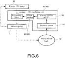
- FIG. 6 is a block diagram of an oil regulating unit.
- a vacuum pump 1 is a vane pump including: a bottomed cylindrical housing 3 in which a pump chamber 2 is formed; a disc-shaped cover 4 that closes the housing 3; a cylindrical rotor 5 that is arranged at a position being eccentric with the center of an approximately circular cross-section of the pump chamber 2; a drive shaft 6 that rotationally drives the rotor 5; a coupling 7 that connects the drive shaft 6 to a rotor of an external drive source; and a plate-shaped vane 8 that is arranged in a state of penetrating the rotor 5 along a diameter direction of the rotor 5.
- a cylindrical bearing portion 32 that surrounds a periphery of the drive shaft 6 is arranged on the side of the outer circumferential face of a bottom portion 31 of the housing 3.
- An approximately circular-arc-shaped (arc-shaped) discharge port 34 being an opening portion of a discharge passage 33 that penetrates the inner face of the bottom portion 31 of the housing 3 and an end face of the bearing portion 32 is arranged at the end face of the bearing portion 32.
- a reed valve 9 is arranged at the discharge port 34 on the end face of the bearing portion 32.
- An O-ring 41 for keeping airtightness is arranged between the housing 3 and the cover 4.
- the housing 3 and the cover 4 are joined with bolts 42.
- the cylindrical rotor 5 is arranged in the housing 3 at the eccentric position in a state that an outer circumferential face of the rotor 5 is substantially contacted to an inner circumferential face of the housing 3.
- An arc-shaped opening portion of the discharge passage 33 on the side of the inner circumferential face of the bottom portion 31 is formed on the inner face of the bottom portion 31 of the housing 3 at a position being slightly on the opposite side in the rotation direction of the rotor 5 from the part where the outer circumferential face of the rotor 5 is in contact with the inner circumferential face of the housing 3 and being between the outer circumferential face of the rotor 5 and the inner circumferential face of the housing 3.
- a suction port 35 is arranged on the inner circumferential face of the housing 3 on the side in the rotation direction of the rotor 5 from the part where the outer circumferential face of the rotor 5 is in contact with the inner circumferential face of the housing 3.
- the suction port 35 communicates with the inside of a suction connection portion 37 that is projecting from the outer circumferential face of the housing 3.
- the suction connection portion 37 is connected to a brake master back 52 (see FIG. 6 ) of a brake booster.
- the suction connection portion 37 includes a check valve 37a at the inside thereof so as to prevent backward flow of air from the pump chamber 2 toward the brake master back 52.
- the cylindrical rotor 5 is connected to the drive shaft 6 and is rotated with a torque transmitted through the coupling 7.
- the drive shaft 6 is connected to a cam shaft of an engine through the coupling 7. Accordingly, the rotor 5 is rotated in a prescribed direction with a drive force of the engine through the cam shaft, the coupling 7, and the drive shaft 6.
- the drive shaft 6 is rotatably axially-supported by the bearing portion 32.
- a flange portion 36 for fixing the vacuum pump 1 is arranged outside the bearing portion 32 of the housing 3 as being laterally extended.
- Two grooves 51 are formed at a cylinder portion of the cylindrical rotor 5 along the diameter direction.
- the vane 8 penetrates the rotor 5 as being inserted to the grooves 51, 51. Further, the vane 8 is arranged to be movable along the length direction, that is, the diameter direction of the rotor 5 in a state of penetrating the rotor 5 in the diameter direction of the rotor 5.
- the pump chamber 2 of the housing 3 is formed as dividing the inner circumferential side of the housing 3 and the outer circumferential side of the rotor 5. That is, the space between the inner circumferential face of the housing 3 and the outer circumferential face of the rotor 5 functions substantially as the pump chamber 2.
- a cap 81 is attached to each end of the vane 8.
- the respective caps 81 are in contact with the inner circumferential face of the housing 3.
- the caps 81 are slide-contacted to the inner circumferential face of the housing 3.
- the pump chamber 2 is divided by the vane 8 into spaces being at the right and left of the vane 8. Since the rotor 5 is eccentric with the pump chamber 2 having an approximately circular cross-section, the vane 8 is rotated as being moved in the diameter direction with respect to the rotor 5 when the rotor 5 is rotated.
- an oil supply hole 40 is formed at the housing 3.
- the oil supply hole 40 is opened to the inner circumferential face of the bearing portion 32 and the outer circumferential face of the drive shaft 6.
- a predetermined gap is formed between the bearing portion 32 and the drive shaft 6. Lubricating oil is supplied to the gap through the oil supply hole 40, and then, supplied into the pump chamber 2 from the gap.
- the vacuum pump (vane pump) 1 having the abovementioned structure is directly fixed to the engine 50.
- a lubricating oil supply passage 44 is connected to the oil supply hole 40 of the vacuum pump 1.
- the lubricating supply passage 44 is formed at the engine 50.
- the lubricating oil supply passage 44 includes a first lubricating oil supply passage 44a extending in parallel to a cam shaft of the engine 50 and a second lubricating oil supply passage 44b extending to the oil supply hole 40 as being perpendicular to the first lubricating oil supply passage 44a.
- a base end of the first lubricating oil supply passage 44a is connected to an unillustrated oil pump.
- a distal end of the second lubricating oil supply passage 44b is connected to the oil supply hole 40. According to the above, lubricating oil flowing through the lubricating oil supply passages 44a, 44b is supplied to the oil supply hole 40.
- the vacuum pump mechanism includes an oil regulating unit 60 capable of adjusting a quantity of lubricating oil flowing through the lubricating oil supply passage 44 when the brake booster reaches a predetermined negative pressure.
- the oil regulating unit 60 includes: a regulating valve 61 capable of changing passage cross-section area of the second lubricating oil supply passage 44b; a drive portion 62 that drives the regulating valve 61; a pressure sensor 63 capable of detecting a pressure of the brake master back 52 of the brake booster; and a control portion 64 that controls the drive portion 62 so that the regulating valve 61 sets the passage cross-section area of the lubricating oil supply passage 44b to be reduced or to be zero when the pressure sensor 63 detects that the brake master back 52 has reached the predetermined negative pressure.
- the regulating valve 61 and the drive portion 62 are arranged at the engine 50.
- the regulating valve 61 is formed into a rod shape.
- the drive portion 62 is structured with a solenoid 62.
- the regulating valve 61 is capable of reciprocating in the axial direction thereof with a magnetic force of the solenoid 62.
- a hole 61b perpendicular to the lubricating oil supply passage 44b is formed at the engine 50.
- the rod-shaped regulating valve 61 is slidably inserted to the hole 61b in the axial direction thereof.
- a penetration portion 61a formed as a hole or a groove is formed at the regulating valve 61 in a direction perpendicular to the axial direction thereof.
- the drive portion (solenoid) 62 is fixed to a side face of the engine 50.
- a concave portion is formed at the side face of the engine 50 and a convex portion is formed at an attaching face of the drive portion 62.
- the drive portion 62 is positioned and fixed to the side face of the engine 50 by fitting the convex portion to the concave portion.
- the control portion 64 is arranged in an engine control unit (ECU) of an automobile.
- the drive portion 62 is connected to the control portion 64.
- the pressure sensor 63 is connected to the control portion 64.
- the control portion 64 receives a signal thereof. Then, the control portion 64 transmits, to the drive portion 62, a signal to drive the regulating valve 61 in the axial direction to set the cross-section area of the lubricating oil supply passage 44b to be reduced or to be zero.
- the rotor 5 is rotated with the drive force of the cam shaft.
- the vane 8 is rotated and sucks air in the brake master back of the brake booster through the suction port 35, so that the brake master back obtains a negative pressure.
- a brake pedal is depressed by a driver, the depressing operation is assisted thereby.
- lubricating oil flows through the lubricating oil supply passages 44a, 44b and is supplied to the pump chamber 2 through the oil supply hole 40 of the vacuum pump 1.
- the passage cross-section area of the lubricating oil supply passage 44b is adjusted by the oil regulating unit 60. That is, when the pressure sensor 63 of the oil regulating unit 60 detects that the pressure of the brake master back 52 has reached the predetermined negative pressure, the control portion 64 receives a signal thereof. Then, the control portion 64 transmits, to the drive portion 62, a signal to drive the regulating valve 61 in the axial direction to set the cross-section area of the lubricating oil supply passage 44b to be reduced or to be zero. Accordingly, the quantity of lubricating oil flowing through the lubricating oil supply passage 44b can be set to a reduced quantity or zero.
- the predetermined negative pressure e.g., minus one atmospheric pressure
- lubricating oil in the pump chamber 2 can be reduced, the load exerted by the lubricating oil to the vane 8 and the like of the vacuum pump 1 can be reduced than before. Accordingly, occurrence of a needless drive torque at the vacuum pump 1 can be suppressed and fuel consumption can be improved.
- the lubricating oil supply passage 44, the regulating valve 61, and the drive portion 62 are arranged at the engine 50, the lubrication oil supply passage 44 and the oil regulating unit 60 can be arranged without modifying the vacuum pump 1.
- FIG. 7 is a sectional view illustrating a second embodiment.
- the lubricating oil supply passage 44, and the regulating valve 61 and the drive portion 62 of the oil regulating unit 60 are arranged at the engine 50.
- a lubricating oil supply passage 45, and a regulating valve 66 and a drive portion 67 of an oil regulating unit 65 are arranged at the housing 3 of the vacuum pump 1. Since the rest of the configuration of the vacuum pump 1 is similar to that in the first embodiment, the same reference is given to the same structural element and description thereof is simplified or skipped.
- the oil regulating unit 65 includes the drive portion 67 arranged at the housing 3, the regulating valve 66, the pressure sensor 63, and the control portion 64.
- the pressure sensor 63 and the control portion 64 are similar to those in the first embodiment.
- the lubricating oil supply passage 45 includes a lubricating oil supply passage 45a connected to the lubricating oil supply passage 44b formed at the engine 50, and a lubricating oil supply passage 45b that is connected to the lubricating oil supply passage 45a and that includes an oil supply hole at a distal end thereof.
- the drive portion 67 is structured with a solenoid 67 similarly to the drive portion 62.
- the regulating valve 66 includes a body portion 66a that is caused by the drive portion 67 to reciprocate in an up-down direction, and a slim rod-shaped valve portion 66b fixed to an upper end face of the body portion 66a.
- the body portion 66a of the regulating valve 66 is caused by the drive portion 62 to reciprocate upward and downward, so that a distal end of the valve portion 66b can adjust a passage cross-section area of the oil supply hole at the distal end of the lubricating oil supply passage 45b. That is, the oil supply hole is closed by the valve portion 66b by lifting the body portion 66a, and the oil supply hole is fully opened by lowering the body portion 66a from the close position.
- the passage cross-section area of the oil supply hole can be adjusted by locating the valve portion 66b between the fully-open position and the close position.
- the drive portion 67 that drives the regulating valve 66 is connected to the control portion 64 and controlled by the control portion 64.
- the pressure senor 63 is connected to the control portion 64.
- the control portion 64 receives a signal thereof.
- the control portion 64 transmits, to the drive portion 67, a signal to drive the regulating valve 66 upward or downward to set the cross-section area of the oil supply hole of the lubricating oil supply passage 45b to be reduc ed or to be zero. Accordingly, the quantity of lubricating oil flowing through the oil supply hole of the lubricating oil supply passage 45b can be set to a reduced quantity or zero.
- the control portion 64 when the pressure sensor 63 of the oil regulating unit 65 detects that the pressure of the brake master back 52 has reached the predetermined negative pressure, the control portion 64 receives the signal thereof. The control portion 64 transmits, to the drive portion 67, the signal to drive the regulating valve 66 upward or downward to set the passage cross-section area of the oil supply hole of the lubricating oil supply passage 45b to be reduced or to be zero. Accordingly, the passage cross-section area of the oil supply hole is set to be reduced or to be zero.
- the lubricating oil in the pump chamber 2 can be reduced, the load exerted by the lubricating oil to the vane 8 and the like of the vacuum pump 1 can be reduced than before. Accordingly, occurrence of a needless drive torque at the vacuum pump 1 can be suppressed and fuel consumption can be improved.
- the lubricating oil supply passage 45, the regulating valve 61, and the drive portion 62 are arranged at the housing 3 of the vacuum pump 1, the lubricating oil supply passage 45 and the oil regulating unit 65 can be arranged without modifying the engine 50.
- FIGs. 8 and 9 illustrate a third embodiment.
- FIG. 8 is a front view and FIG. 9 is a sectional view.
- the oil regulating unit 60, 65 is configured to include the regulating valve 61, 66, the drive portions 62, 67, the pressure sensor 63, 63, the control portions 64, 64, and the like.
- the oil regulating unit 70 is configured to include the regulating valve 61 capable of changing passage cross-section area of the lubricating oil supply passage 44b and a negative pressure actuator 71 that drives the regulating valve 61. Since the rest of the configuration of the vacuum pump 1 is similar to that in the first embodiment, the same reference is given to the same structural element and description thereof is simplified or skipped.
- the negative pressure actuator 71 is connected to a negative pressure passage that is connected to the suction port 35.
- the suction port 35 communicates with the inside of the suction connection portion 37 protruded from the outer circumferential face of the housing 3.
- the suction connection portion 37 is connected to the brake master back 52 (see FIG. 6 ) of the brake booster with an unillustrated pipe.
- the negative pressure passage is structured with the pipe and the suction connection portion 37.
- the suction connection portion 37 includes a bifurcation portion 37b.
- the bifurcation portion 37b is connected to a pipe 72 and the pipe 72 is connected to the negative pressure actuator 71.
- the negative pressure actuator 71 is connected to the negative pressure passage through the pipe 72.
- the negative pressure actuator 71 includes a pressure chamber 71a and a spring 71b at the inside thereof.
- the pressure chamber 71a is provided with a negative pressure
- the regulating valve 61 is moved leftward in the axial direction thereof against an urging force of the spring 71b. Then, when the penetration portion 61a of the regulating valve 61 is located at the lubricating oil supply passage 44b, lubrication oil flows toward the oil supply hole 40 through the lubricating oil supply passage 44b.
- the regulating valve 61 When the negative pressure of the pressure chamber 71a is released, the regulating valve 61 is moved rightward in the axial direction thereof with the urging force of the spring 71b.
- the outer circumferential part of the regulating valve 61 other than the penetration portion 61a is located at the lubricating oil supply passage 44b, supplying of lubricating oil is discontinued. Further, owing to that the regulating valve 61 is caused to slide in the axial direction to move the penetration portion 61a laterally, the passage cross-section area of the penetration portion 61a is increased and decreased at the intersection part between the lubricating oil supply passage 44b and the hole 61b. Thus, a flow rate of lubricating oil flowing through the lubricating oil supply passage 44b can be adjusted.
- a switching valve 73 is arranged at a midpoint of the pipe 72.
- the switching valve 73 When the switching valve 73 is turned on, the brake master back 52 and the negative pressure actuator 71 are in a communicating state.
- the switching valve 73 When the switching valve 73 is turned off, the brake master back 52 and the negative pressure actuator 71 are in a non-communicating state.
- the pressure of the brake master back 52 is detected by the pressure sensor 63 and the control portion 64 performs ON/OFF control of the switching valve 73 based on the detection value.
- the switching valve 73 When the brake master back 52 reaches the predetermined negative pressure, the switching valve 73 is turned on and the brake master back 52 and the negative pressure actuator 71 are caused to be in the communicating state.
- the negative pressure actuator 71 drives (moves) the regulating valve 61 with the negative pressure, so that the passage cross-section area of the lubricating oil supply passage 44b is increased and decreased. Thus, a flow rate of lubricating oil flowing through the lubricating oil supply passage 44b can be adjusted.
- the negative pressure actuator 71 is connected through the pipe 72 to the negative pressure passage that is connected to the suction port 35. Accordingly, when the brake master back 52 of the brake booster reaches the predetermined negative pressure, the negative pressure actuator 71 drives the regulating valve 61 with the negative pressure to control the passage cross-section area of the lubricating oil supply passage 44b to be reduced. Therefore, not like the first and second embodiments, the regulating valve 61 is not necessarily required to be controlled separately by electrical control or the like.
- FIGs. 10 and 11 illustrate a fourth embodiment.
- FIG. 10 is a sectional view.
- FIG. 11 is a block diagram of an oil regulating unit.
- the oil regulating unit is configured to include the regulating valve 61 capable of changing passage cross-section area of the lubricating oil supply passage 44b, the negative pressure actuator 71 that drives the regulating valve 61, and a restricting valve 75.
- the negative pressure actuator 71 is connected to the negative pressure passage that is connected to the suction port 35. That is, the suction connection portion 37 structuring the negative pressure passage is connected to the brake master back 52 through a pipe 72, the pipe 72 is connected to the bifurcation portion 37b of the suction connection portion 37, and the pipe 72 is connected to the negative pressure actuator 71. Thus, the negative pressure actuator 71 is connected to the negative pressure passage through the pipe 72.
- the restricting valve 75 is arranged at a midpoint of the pipe 72.
- the restricting valve 75 is arranged for reducing work of the vacuum pump by reducing the oil quantity after the brake master back 52 reliably reaches negative pressure.
- the negative pressure actuator 71 drives the regulating valve 61 with the negative pressure, so that the passage cross-section of the lubrication oil supply passage 44b is increased and decreased.
- a flow rate of lubrication oil flowing through the lubricating oil supply passage 44b can be adjusted.
- the negative pressure actuator 71 drives the regulating valve 61 with the negative pressure to control the passage cross-section area of the lubricating oil supply passage 44b to be reduced. Therefore, not like the first and second embodiments, the regulating valve 61 is not necessarily required to be controlled separately by electrical control or the like.
- the pressure of the brake master back 52 is detected by the pressure sensor 63 and the control portion 64 performs ON/OFF control of the switching valve 73 based on the detection value.
- the control portion 64 since the negative pressure actuator 71 is operated when the negative pressure passage reaches the predetermined negative pressure with the restricting valve 75 functioning as a passage resistance of the pipe 72, the control portion 64 becomes unnecessary. Accordingly, the regulating valve 61 can be driven completely without electrical control.
Landscapes
- Engineering & Computer Science (AREA)
- Mechanical Engineering (AREA)
- General Engineering & Computer Science (AREA)
- Transportation (AREA)
- Applications Or Details Of Rotary Compressors (AREA)
- Valves And Accessory Devices For Braking Systems (AREA)
Claims (5)
- Mécanisme de pompe à vide, comprenant :un logement (3) incluant une chambre à pompe (2) et un port d'aspiration (35) ;un rotor (5) qui est rotatif sur une position étant excentrique avec un centre de la chambre à pompe (2) et est tourné avec une force d'entraînement d'un moteur (50) ;une pale (8) qui divise la chambre à pompe (2) en une pluralité d'espaces étant tournés avec le rotor (5) ;un passage d'alimentation d'huile lubrifiante (44, 44a, 44b, 45, 45a, 45b) qui fournit de l'huile lubrifiante à la chambre à pompe (2) ; etune unité de régulation de l'huile (60, 65, 70),le mécanisme de pompe à vide étant caractérisé en ce que le port d'aspiration (35) est connecté à un servofrein (52) et que l'unité de régulation de l'huile (60, 65, 70) est capable d'ajuster une quantité d'huile lubrifiante s'écoulant à travers le passage d'alimentation d'huile lubrifiante (44, 44a, 44b, 45, 45a, 45b) à une quantité réduite ou à zéro lorsque le servofrein (52) atteint une pression négative prédéterminée.
- Mécanisme de pompe à vide selon la revendication 1, dans lequel l'unité de régulation de l'huile (60) inclut :une soupape de régulation (61) capable de modifier l'aire transversale de passage du passage d'alimentation d'huile lubrifiante (44b) ;une partie d'entraînement (62) qui entraîne la soupape de régulation (61) ;un capteur de pression (63) capable de détecter une pression du servofrein (52) ; etune partie de commande (64) qui commande la partie d'entraînement (62) de façon à ce que la soupape de régulation (61) réduise l'aire transversale de passage du passage d'alimentation d'huile lubrifiante (44b) lorsque le capteur de pression (63) détecte que le servofrein (52) atteint la pression négative prédéterminée.
- Mécanisme de pompe à vide selon la revendication 2, dans lequel
le passage d'alimentation d'huile lubrifiante (44), la soupape de régulation (61) et la partie d'entraînement (62) sont agencés sur le moteur (50). - Mécanisme de pompe à vide selon la revendication 2, dans lequel
le passage d'alimentation d'huile lubrifiante (45), la soupape de régulation (66) et la partie d'entraînement (67) sont agencés dans le logement (3). - Mécanisme de pompe à vide selon la revendication 1, dans lequel l'unité de régulation de l'huile (70) inclut :une soupape de régulation (61) capable de modifier l'aire transversale de passage du passage d'alimentation d'huile lubrifiante (44b) ; etun déclencheur de pression négative (71) qui entraîne la soupape de régulation (61),dans lequel le déclencheur de pression négative (71) est connecté à un passage de pression négative qui est connecté au port d'aspiration (35), etle déclencheur de pression négative (71) entraîne la soupape de régulation (61), lorsque le servofrein (52) atteint la pression négative prédéterminée, en utilisant la pression négative, de façon à réduire l'aire transversale de passage du passage d'alimentation d'huile lubrifiante (44b).
Applications Claiming Priority (2)
| Application Number | Priority Date | Filing Date | Title |
|---|---|---|---|
| JP2013172156A JP6305708B2 (ja) | 2013-08-22 | 2013-08-22 | バキュームポンプ機構 |
| PCT/JP2014/071163 WO2015025755A1 (fr) | 2013-08-22 | 2014-08-11 | Mécanisme de pompe à vide |
Publications (3)
| Publication Number | Publication Date |
|---|---|
| EP3037667A1 EP3037667A1 (fr) | 2016-06-29 |
| EP3037667A4 EP3037667A4 (fr) | 2017-01-18 |
| EP3037667B1 true EP3037667B1 (fr) | 2018-05-23 |
Family
ID=52483532
Family Applications (1)
| Application Number | Title | Priority Date | Filing Date |
|---|---|---|---|
| EP14837752.6A Not-in-force EP3037667B1 (fr) | 2013-08-22 | 2014-08-11 | Mécanisme de pompe à vide |
Country Status (5)
| Country | Link |
|---|---|
| US (1) | US20160201676A1 (fr) |
| EP (1) | EP3037667B1 (fr) |
| JP (1) | JP6305708B2 (fr) |
| CN (1) | CN105518303B (fr) |
| WO (1) | WO2015025755A1 (fr) |
Families Citing this family (4)
| Publication number | Priority date | Publication date | Assignee | Title |
|---|---|---|---|---|
| CN106322087A (zh) * | 2016-10-09 | 2017-01-11 | 天津盛欣佳业科技有限公司 | 一种耐用型真空泵 |
| DE102017011791A1 (de) * | 2017-12-20 | 2019-06-27 | Daimler Ag | Ölversorgungseinrichtung für eine Unterdruckpumpe einer Verbrennungskraftmaschine |
| CN109268269B (zh) * | 2018-11-15 | 2024-07-26 | 上海肇民动力科技有限公司 | 真空泵 |
| CN114109822B (zh) * | 2020-08-25 | 2023-11-14 | 精工爱普生株式会社 | 真空装置 |
Family Cites Families (12)
| Publication number | Priority date | Publication date | Assignee | Title |
|---|---|---|---|---|
| US3265295A (en) * | 1964-07-31 | 1966-08-09 | New York Air Brake Co | Pump |
| GB2076472A (en) * | 1980-05-22 | 1981-12-02 | Bosch Gmbh Robert | A vane-type rotary pump |
| JPS6411385A (en) * | 1987-07-06 | 1989-01-13 | Mitsubishi Electric Corp | Pulse laser system |
| JPS6411385U (fr) * | 1987-07-09 | 1989-01-20 | ||
| JP2004011421A (ja) | 2002-06-03 | 2004-01-15 | Toyoda Mach Works Ltd | ベーン式バキュームポンプ |
| JP3874300B2 (ja) | 2005-02-16 | 2007-01-31 | 大豊工業株式会社 | ベーンポンプ |
| GB0607198D0 (en) * | 2006-04-10 | 2006-05-17 | Wabco Automotive Uk Ltd | Improved vacuum pump |
| JP2008157070A (ja) * | 2006-12-21 | 2008-07-10 | Toyota Motor Corp | バキュームポンプ |
| JP5157885B2 (ja) * | 2008-12-25 | 2013-03-06 | トヨタ自動車株式会社 | バキュームポンプ |
| JP5195611B2 (ja) * | 2009-04-22 | 2013-05-08 | トヨタ自動車株式会社 | バキュームポンプ |
| CN102278310A (zh) * | 2011-07-14 | 2011-12-14 | 温州市欧弗斯机械有限公司 | 智能调节真空系统 |
| CN202546213U (zh) * | 2012-08-21 | 2012-11-21 | 绵阳市万欣测控技术有限公司 | 一种流量调节式机油泵 |
-
2013
- 2013-08-22 JP JP2013172156A patent/JP6305708B2/ja active Active
-
2014
- 2014-08-11 WO PCT/JP2014/071163 patent/WO2015025755A1/fr not_active Ceased
- 2014-08-11 US US14/913,372 patent/US20160201676A1/en not_active Abandoned
- 2014-08-11 CN CN201480046086.XA patent/CN105518303B/zh not_active Expired - Fee Related
- 2014-08-11 EP EP14837752.6A patent/EP3037667B1/fr not_active Not-in-force
Non-Patent Citations (1)
| Title |
|---|
| None * |
Also Published As
| Publication number | Publication date |
|---|---|
| EP3037667A1 (fr) | 2016-06-29 |
| CN105518303A (zh) | 2016-04-20 |
| JP6305708B2 (ja) | 2018-04-04 |
| EP3037667A4 (fr) | 2017-01-18 |
| US20160201676A1 (en) | 2016-07-14 |
| CN105518303B (zh) | 2018-06-29 |
| WO2015025755A1 (fr) | 2015-02-26 |
| JP2015040512A (ja) | 2015-03-02 |
Similar Documents
| Publication | Publication Date | Title |
|---|---|---|
| US8684473B2 (en) | Gear pump and gear pump for brake apparatus | |
| EP3037667B1 (fr) | Mécanisme de pompe à vide | |
| CN103174644A (zh) | 可变容量型油泵 | |
| CN103835941A (zh) | 容量可变型泵 | |
| US10443584B2 (en) | Fluid pressure pump and fluid pressure system | |
| US11767002B2 (en) | Brake hydraulic pressure controller | |
| US7862305B2 (en) | Variable displacement vane pump | |
| CN103547800B (zh) | 伺服调节器 | |
| JP3386052B2 (ja) | ポンプ装置 | |
| JP5090883B2 (ja) | 2容量ポンプ | |
| WO2018056027A1 (fr) | Pompe à piston et dispositif de frein | |
| US10233899B2 (en) | Hydrostatic axial piston machine | |
| EP2832999B1 (fr) | Moteur de pompe hydraulique | |
| JP6796291B2 (ja) | エアシリンダ | |
| JP6447362B2 (ja) | 可変容量型斜板式液圧回転機 | |
| JP6106493B2 (ja) | シャトル弁及びそれを備えたポンプユニット | |
| JP5915601B2 (ja) | ピストンポンプ | |
| JP6658467B2 (ja) | ピストンポンプ | |
| JP2005069138A (ja) | ギヤポンプ | |
| JP2018151032A (ja) | 流体圧シリンダ及び流体圧駆動ユニット | |
| JP2009090900A (ja) | 電動式ブレーキ倍力装置 | |
| WO2018139067A1 (fr) | Circuit hydraulique | |
| JP2019055664A (ja) | ポンプ装置及びブレーキ装置 | |
| JP2017025880A (ja) | ポンプ装置 | |
| KR20050110050A (ko) | 전자제어 식 브레이크 시스템용 펌프 |
Legal Events
| Date | Code | Title | Description |
|---|---|---|---|
| PUAI | Public reference made under article 153(3) epc to a published international application that has entered the european phase |
Free format text: ORIGINAL CODE: 0009012 |
|
| 17P | Request for examination filed |
Effective date: 20160219 |
|
| AK | Designated contracting states |
Kind code of ref document: A1 Designated state(s): AL AT BE BG CH CY CZ DE DK EE ES FI FR GB GR HR HU IE IS IT LI LT LU LV MC MK MT NL NO PL PT RO RS SE SI SK SM TR |
|
| AX | Request for extension of the european patent |
Extension state: BA ME |
|
| DAX | Request for extension of the european patent (deleted) | ||
| A4 | Supplementary search report drawn up and despatched |
Effective date: 20161216 |
|
| RIC1 | Information provided on ipc code assigned before grant |
Ipc: F04C 25/02 20060101ALI20161212BHEP Ipc: F04C 29/02 20060101AFI20161212BHEP Ipc: B60T 17/02 20060101ALI20161212BHEP Ipc: B60T 13/52 20060101ALI20161212BHEP Ipc: F04C 18/344 20060101ALI20161212BHEP |
|
| GRAP | Despatch of communication of intention to grant a patent |
Free format text: ORIGINAL CODE: EPIDOSNIGR1 |
|
| STAA | Information on the status of an ep patent application or granted ep patent |
Free format text: STATUS: GRANT OF PATENT IS INTENDED |
|
| RIC1 | Information provided on ipc code assigned before grant |
Ipc: F04C 29/02 20060101AFI20171129BHEP Ipc: B60T 13/52 20060101ALI20171129BHEP Ipc: B60T 17/02 20060101ALI20171129BHEP Ipc: F04C 25/02 20060101ALI20171129BHEP Ipc: F04C 18/344 20060101ALI20171129BHEP |
|
| INTG | Intention to grant announced |
Effective date: 20180103 |
|
| GRAS | Grant fee paid |
Free format text: ORIGINAL CODE: EPIDOSNIGR3 |
|
| GRAA | (expected) grant |
Free format text: ORIGINAL CODE: 0009210 |
|
| STAA | Information on the status of an ep patent application or granted ep patent |
Free format text: STATUS: THE PATENT HAS BEEN GRANTED |
|
| AK | Designated contracting states |
Kind code of ref document: B1 Designated state(s): AL AT BE BG CH CY CZ DE DK EE ES FI FR GB GR HR HU IE IS IT LI LT LU LV MC MK MT NL NO PL PT RO RS SE SI SK SM TR |
|
| REG | Reference to a national code |
Ref country code: GB Ref legal event code: FG4D |
|
| REG | Reference to a national code |
Ref country code: CH Ref legal event code: EP |
|
| REG | Reference to a national code |
Ref country code: IE Ref legal event code: FG4D |
|
| REG | Reference to a national code |
Ref country code: AT Ref legal event code: REF Ref document number: 1001743 Country of ref document: AT Kind code of ref document: T Effective date: 20180615 |
|
| REG | Reference to a national code |
Ref country code: DE Ref legal event code: R096 Ref document number: 602014025982 Country of ref document: DE |
|
| REG | Reference to a national code |
Ref country code: FR Ref legal event code: PLFP Year of fee payment: 5 |
|
| PGFP | Annual fee paid to national office [announced via postgrant information from national office to epo] |
Ref country code: FR Payment date: 20180625 Year of fee payment: 5 |
|
| REG | Reference to a national code |
Ref country code: NL Ref legal event code: MP Effective date: 20180523 |
|
| REG | Reference to a national code |
Ref country code: LT Ref legal event code: MG4D |
|
| PG25 | Lapsed in a contracting state [announced via postgrant information from national office to epo] |
Ref country code: ES Free format text: LAPSE BECAUSE OF FAILURE TO SUBMIT A TRANSLATION OF THE DESCRIPTION OR TO PAY THE FEE WITHIN THE PRESCRIBED TIME-LIMIT Effective date: 20180523 Ref country code: FI Free format text: LAPSE BECAUSE OF FAILURE TO SUBMIT A TRANSLATION OF THE DESCRIPTION OR TO PAY THE FEE WITHIN THE PRESCRIBED TIME-LIMIT Effective date: 20180523 Ref country code: BG Free format text: LAPSE BECAUSE OF FAILURE TO SUBMIT A TRANSLATION OF THE DESCRIPTION OR TO PAY THE FEE WITHIN THE PRESCRIBED TIME-LIMIT Effective date: 20180823 Ref country code: LT Free format text: LAPSE BECAUSE OF FAILURE TO SUBMIT A TRANSLATION OF THE DESCRIPTION OR TO PAY THE FEE WITHIN THE PRESCRIBED TIME-LIMIT Effective date: 20180523 Ref country code: NO Free format text: LAPSE BECAUSE OF FAILURE TO SUBMIT A TRANSLATION OF THE DESCRIPTION OR TO PAY THE FEE WITHIN THE PRESCRIBED TIME-LIMIT Effective date: 20180823 Ref country code: SE Free format text: LAPSE BECAUSE OF FAILURE TO SUBMIT A TRANSLATION OF THE DESCRIPTION OR TO PAY THE FEE WITHIN THE PRESCRIBED TIME-LIMIT Effective date: 20180523 |
|
| PGFP | Annual fee paid to national office [announced via postgrant information from national office to epo] |
Ref country code: IT Payment date: 20180829 Year of fee payment: 5 |
|
| PG25 | Lapsed in a contracting state [announced via postgrant information from national office to epo] |
Ref country code: GR Free format text: LAPSE BECAUSE OF FAILURE TO SUBMIT A TRANSLATION OF THE DESCRIPTION OR TO PAY THE FEE WITHIN THE PRESCRIBED TIME-LIMIT Effective date: 20180824 Ref country code: HR Free format text: LAPSE BECAUSE OF FAILURE TO SUBMIT A TRANSLATION OF THE DESCRIPTION OR TO PAY THE FEE WITHIN THE PRESCRIBED TIME-LIMIT Effective date: 20180523 Ref country code: RS Free format text: LAPSE BECAUSE OF FAILURE TO SUBMIT A TRANSLATION OF THE DESCRIPTION OR TO PAY THE FEE WITHIN THE PRESCRIBED TIME-LIMIT Effective date: 20180523 Ref country code: LV Free format text: LAPSE BECAUSE OF FAILURE TO SUBMIT A TRANSLATION OF THE DESCRIPTION OR TO PAY THE FEE WITHIN THE PRESCRIBED TIME-LIMIT Effective date: 20180523 Ref country code: NL Free format text: LAPSE BECAUSE OF FAILURE TO SUBMIT A TRANSLATION OF THE DESCRIPTION OR TO PAY THE FEE WITHIN THE PRESCRIBED TIME-LIMIT Effective date: 20180523 |
|
| REG | Reference to a national code |
Ref country code: AT Ref legal event code: MK05 Ref document number: 1001743 Country of ref document: AT Kind code of ref document: T Effective date: 20180523 |
|
| PG25 | Lapsed in a contracting state [announced via postgrant information from national office to epo] |
Ref country code: CZ Free format text: LAPSE BECAUSE OF FAILURE TO SUBMIT A TRANSLATION OF THE DESCRIPTION OR TO PAY THE FEE WITHIN THE PRESCRIBED TIME-LIMIT Effective date: 20180523 Ref country code: SK Free format text: LAPSE BECAUSE OF FAILURE TO SUBMIT A TRANSLATION OF THE DESCRIPTION OR TO PAY THE FEE WITHIN THE PRESCRIBED TIME-LIMIT Effective date: 20180523 Ref country code: RO Free format text: LAPSE BECAUSE OF FAILURE TO SUBMIT A TRANSLATION OF THE DESCRIPTION OR TO PAY THE FEE WITHIN THE PRESCRIBED TIME-LIMIT Effective date: 20180523 Ref country code: PL Free format text: LAPSE BECAUSE OF FAILURE TO SUBMIT A TRANSLATION OF THE DESCRIPTION OR TO PAY THE FEE WITHIN THE PRESCRIBED TIME-LIMIT Effective date: 20180523 Ref country code: DK Free format text: LAPSE BECAUSE OF FAILURE TO SUBMIT A TRANSLATION OF THE DESCRIPTION OR TO PAY THE FEE WITHIN THE PRESCRIBED TIME-LIMIT Effective date: 20180523 Ref country code: AT Free format text: LAPSE BECAUSE OF FAILURE TO SUBMIT A TRANSLATION OF THE DESCRIPTION OR TO PAY THE FEE WITHIN THE PRESCRIBED TIME-LIMIT Effective date: 20180523 Ref country code: EE Free format text: LAPSE BECAUSE OF FAILURE TO SUBMIT A TRANSLATION OF THE DESCRIPTION OR TO PAY THE FEE WITHIN THE PRESCRIBED TIME-LIMIT Effective date: 20180523 |
|
| REG | Reference to a national code |
Ref country code: DE Ref legal event code: R097 Ref document number: 602014025982 Country of ref document: DE |
|
| PG25 | Lapsed in a contracting state [announced via postgrant information from national office to epo] |
Ref country code: SM Free format text: LAPSE BECAUSE OF FAILURE TO SUBMIT A TRANSLATION OF THE DESCRIPTION OR TO PAY THE FEE WITHIN THE PRESCRIBED TIME-LIMIT Effective date: 20180523 |
|
| PG25 | Lapsed in a contracting state [announced via postgrant information from national office to epo] |
Ref country code: MC Free format text: LAPSE BECAUSE OF FAILURE TO SUBMIT A TRANSLATION OF THE DESCRIPTION OR TO PAY THE FEE WITHIN THE PRESCRIBED TIME-LIMIT Effective date: 20180523 |
|
| PLBE | No opposition filed within time limit |
Free format text: ORIGINAL CODE: 0009261 |
|
| REG | Reference to a national code |
Ref country code: CH Ref legal event code: PL |
|
| STAA | Information on the status of an ep patent application or granted ep patent |
Free format text: STATUS: NO OPPOSITION FILED WITHIN TIME LIMIT |
|
| GBPC | Gb: european patent ceased through non-payment of renewal fee |
Effective date: 20180823 |
|
| PG25 | Lapsed in a contracting state [announced via postgrant information from national office to epo] |
Ref country code: CH Free format text: LAPSE BECAUSE OF NON-PAYMENT OF DUE FEES Effective date: 20180831 Ref country code: LI Free format text: LAPSE BECAUSE OF NON-PAYMENT OF DUE FEES Effective date: 20180831 Ref country code: LU Free format text: LAPSE BECAUSE OF NON-PAYMENT OF DUE FEES Effective date: 20180811 |
|
| 26N | No opposition filed |
Effective date: 20190226 |
|
| REG | Reference to a national code |
Ref country code: BE Ref legal event code: MM Effective date: 20180831 |
|
| REG | Reference to a national code |
Ref country code: IE Ref legal event code: MM4A |
|
| PG25 | Lapsed in a contracting state [announced via postgrant information from national office to epo] |
Ref country code: SI Free format text: LAPSE BECAUSE OF FAILURE TO SUBMIT A TRANSLATION OF THE DESCRIPTION OR TO PAY THE FEE WITHIN THE PRESCRIBED TIME-LIMIT Effective date: 20180523 |
|
| PG25 | Lapsed in a contracting state [announced via postgrant information from national office to epo] |
Ref country code: IE Free format text: LAPSE BECAUSE OF NON-PAYMENT OF DUE FEES Effective date: 20180811 |
|
| PG25 | Lapsed in a contracting state [announced via postgrant information from national office to epo] |
Ref country code: BE Free format text: LAPSE BECAUSE OF NON-PAYMENT OF DUE FEES Effective date: 20180831 |
|
| PG25 | Lapsed in a contracting state [announced via postgrant information from national office to epo] |
Ref country code: GB Free format text: LAPSE BECAUSE OF NON-PAYMENT OF DUE FEES Effective date: 20180823 |
|
| PG25 | Lapsed in a contracting state [announced via postgrant information from national office to epo] |
Ref country code: AL Free format text: LAPSE BECAUSE OF FAILURE TO SUBMIT A TRANSLATION OF THE DESCRIPTION OR TO PAY THE FEE WITHIN THE PRESCRIBED TIME-LIMIT Effective date: 20180523 |
|
| PG25 | Lapsed in a contracting state [announced via postgrant information from national office to epo] |
Ref country code: MT Free format text: LAPSE BECAUSE OF NON-PAYMENT OF DUE FEES Effective date: 20180811 |
|
| PG25 | Lapsed in a contracting state [announced via postgrant information from national office to epo] |
Ref country code: TR Free format text: LAPSE BECAUSE OF FAILURE TO SUBMIT A TRANSLATION OF THE DESCRIPTION OR TO PAY THE FEE WITHIN THE PRESCRIBED TIME-LIMIT Effective date: 20180523 |
|
| PG25 | Lapsed in a contracting state [announced via postgrant information from national office to epo] |
Ref country code: PT Free format text: LAPSE BECAUSE OF FAILURE TO SUBMIT A TRANSLATION OF THE DESCRIPTION OR TO PAY THE FEE WITHIN THE PRESCRIBED TIME-LIMIT Effective date: 20180523 |
|
| PG25 | Lapsed in a contracting state [announced via postgrant information from national office to epo] |
Ref country code: MK Free format text: LAPSE BECAUSE OF NON-PAYMENT OF DUE FEES Effective date: 20180523 Ref country code: CY Free format text: LAPSE BECAUSE OF FAILURE TO SUBMIT A TRANSLATION OF THE DESCRIPTION OR TO PAY THE FEE WITHIN THE PRESCRIBED TIME-LIMIT Effective date: 20180523 Ref country code: HU Free format text: LAPSE BECAUSE OF FAILURE TO SUBMIT A TRANSLATION OF THE DESCRIPTION OR TO PAY THE FEE WITHIN THE PRESCRIBED TIME-LIMIT; INVALID AB INITIO Effective date: 20140811 |
|
| PG25 | Lapsed in a contracting state [announced via postgrant information from national office to epo] |
Ref country code: FR Free format text: LAPSE BECAUSE OF NON-PAYMENT OF DUE FEES Effective date: 20190831 Ref country code: IS Free format text: LAPSE BECAUSE OF FAILURE TO SUBMIT A TRANSLATION OF THE DESCRIPTION OR TO PAY THE FEE WITHIN THE PRESCRIBED TIME-LIMIT Effective date: 20180923 |
|
| PG25 | Lapsed in a contracting state [announced via postgrant information from national office to epo] |
Ref country code: IT Free format text: LAPSE BECAUSE OF NON-PAYMENT OF DUE FEES Effective date: 20190811 |
|
| PGFP | Annual fee paid to national office [announced via postgrant information from national office to epo] |
Ref country code: DE Payment date: 20230627 Year of fee payment: 10 |
|
| REG | Reference to a national code |
Ref country code: DE Ref legal event code: R119 Ref document number: 602014025982 Country of ref document: DE |
|
| PG25 | Lapsed in a contracting state [announced via postgrant information from national office to epo] |
Ref country code: DE Free format text: LAPSE BECAUSE OF NON-PAYMENT OF DUE FEES Effective date: 20250301 |