EP3037762A1 - Kühlvorrichtung - Google Patents
Kühlvorrichtung Download PDFInfo
- Publication number
- EP3037762A1 EP3037762A1 EP15199330.0A EP15199330A EP3037762A1 EP 3037762 A1 EP3037762 A1 EP 3037762A1 EP 15199330 A EP15199330 A EP 15199330A EP 3037762 A1 EP3037762 A1 EP 3037762A1
- Authority
- EP
- European Patent Office
- Prior art keywords
- vacuum pump
- housing
- chamber
- refrigerating device
- storage chamber
- Prior art date
- Legal status (The legal status is an assumption and is not a legal conclusion. Google has not performed a legal analysis and makes no representation as to the accuracy of the status listed.)
- Withdrawn
Links
- 230000004308 accommodation Effects 0.000 claims description 59
- 230000008014 freezing Effects 0.000 claims description 18
- 238000007710 freezing Methods 0.000 claims description 18
- 238000005265 energy consumption Methods 0.000 abstract description 9
- 239000007789 gas Substances 0.000 description 23
- 238000005187 foaming Methods 0.000 description 6
- 238000000034 method Methods 0.000 description 6
- 239000007788 liquid Substances 0.000 description 4
- 238000007599 discharging Methods 0.000 description 2
- 238000009434 installation Methods 0.000 description 2
- 238000004904 shortening Methods 0.000 description 2
- 230000009466 transformation Effects 0.000 description 2
- QVGXLLKOCUKJST-UHFFFAOYSA-N atomic oxygen Chemical compound [O] QVGXLLKOCUKJST-UHFFFAOYSA-N 0.000 description 1
- 230000000694 effects Effects 0.000 description 1
- 238000005516 engineering process Methods 0.000 description 1
- -1 for example Substances 0.000 description 1
- 238000012986 modification Methods 0.000 description 1
- 230000004048 modification Effects 0.000 description 1
- 239000001301 oxygen Substances 0.000 description 1
- 229910052760 oxygen Inorganic materials 0.000 description 1
- 239000007779 soft material Substances 0.000 description 1
Images



Classifications
-
- F—MECHANICAL ENGINEERING; LIGHTING; HEATING; WEAPONS; BLASTING
- F25—REFRIGERATION OR COOLING; COMBINED HEATING AND REFRIGERATION SYSTEMS; HEAT PUMP SYSTEMS; MANUFACTURE OR STORAGE OF ICE; LIQUEFACTION SOLIDIFICATION OF GASES
- F25D—REFRIGERATORS; COLD ROOMS; ICE-BOXES; COOLING OR FREEZING APPARATUS NOT OTHERWISE PROVIDED FOR
- F25D11/00—Self-contained movable devices, e.g. domestic refrigerators
- F25D11/02—Self-contained movable devices, e.g. domestic refrigerators with cooling compartments at different temperatures
-
- F—MECHANICAL ENGINEERING; LIGHTING; HEATING; WEAPONS; BLASTING
- F25—REFRIGERATION OR COOLING; COMBINED HEATING AND REFRIGERATION SYSTEMS; HEAT PUMP SYSTEMS; MANUFACTURE OR STORAGE OF ICE; LIQUEFACTION SOLIDIFICATION OF GASES
- F25D—REFRIGERATORS; COLD ROOMS; ICE-BOXES; COOLING OR FREEZING APPARATUS NOT OTHERWISE PROVIDED FOR
- F25D17/00—Arrangements for circulating cooling fluids; Arrangements for circulating gas, e.g. air, within refrigerated spaces
- F25D17/04—Arrangements for circulating cooling fluids; Arrangements for circulating gas, e.g. air, within refrigerated spaces for circulating air, e.g. by convection
- F25D17/042—Air treating means within refrigerated spaces
-
- F—MECHANICAL ENGINEERING; LIGHTING; HEATING; WEAPONS; BLASTING
- F25—REFRIGERATION OR COOLING; COMBINED HEATING AND REFRIGERATION SYSTEMS; HEAT PUMP SYSTEMS; MANUFACTURE OR STORAGE OF ICE; LIQUEFACTION SOLIDIFICATION OF GASES
- F25D—REFRIGERATORS; COLD ROOMS; ICE-BOXES; COOLING OR FREEZING APPARATUS NOT OTHERWISE PROVIDED FOR
- F25D2317/00—Details or arrangements for circulating cooling fluids; Details or arrangements for circulating gas, e.g. air, within refrigerated spaces, not provided for in other groups of this subclass
- F25D2317/04—Treating air flowing to refrigeration compartments
- F25D2317/043—Treating air flowing to refrigeration compartments by creating a vacuum in a storage compartment
-
- F—MECHANICAL ENGINEERING; LIGHTING; HEATING; WEAPONS; BLASTING
- F25—REFRIGERATION OR COOLING; COMBINED HEATING AND REFRIGERATION SYSTEMS; HEAT PUMP SYSTEMS; MANUFACTURE OR STORAGE OF ICE; LIQUEFACTION SOLIDIFICATION OF GASES
- F25D—REFRIGERATORS; COLD ROOMS; ICE-BOXES; COOLING OR FREEZING APPARATUS NOT OTHERWISE PROVIDED FOR
- F25D2317/00—Details or arrangements for circulating cooling fluids; Details or arrangements for circulating gas, e.g. air, within refrigerated spaces, not provided for in other groups of this subclass
- F25D2317/06—Details or arrangements for circulating cooling fluids; Details or arrangements for circulating gas, e.g. air, within refrigerated spaces, not provided for in other groups of this subclass with forced air circulation
- F25D2317/061—Details or arrangements for circulating cooling fluids; Details or arrangements for circulating gas, e.g. air, within refrigerated spaces, not provided for in other groups of this subclass with forced air circulation through special compartments
Definitions
- the present utility model relates to a refrigerating device, and particularly to a refrigerating device having an evacuatable chamber.
- the existing refrigerating device adopts an evacuatable chamber to reduce oxygen content in the chamber so as to increase storage effects of items, thereby prolonging storage time.
- the evacuatable chamber (which may also be called “low-pressure chamber”) uses a vacuum pump for evacuation.
- An object of the present utility model is to provide a refrigerating device having an evacuatable chamber that can further reduce energy consumption.
- the present utility model provides a refrigerating device, including at least two storage chambers, a housing defining an evacuatable chamber and a vacuum pump used to evacuate the chamber, wherein the housing is disposed in one storage chamber, and exhaust of the vacuum pump is introduced into at least one of the two storage chambers.
- the technical solution has the following advantages: as the housing is disposed in one storage chamber, gas pumped out by the vacuum pump from the chamber defined by the housing is low-temperature gas, discharged gas is also low-temperature gas, and relative to that the low-temperature gas is discharged outside the refrigerating device and the storage chamber cools normal-temperature gas entering from the outside, the low-temperature gas discharged by the vacuum pump is directly introduced into any storage chamber or multiple storage chambers, which can reduce energy consumption.
- the "evacuatable chamber” in the present utility model refers to that the chamber is evacuatable and has pressure which is lower than atmospheric pressure, for example, the chamber can be decompressed to make the pressure in the chamber kept between the atmospheric pressure and absolute vacuum.
- the evacuatable chamber may also be called “low-pressure chamber” or “vacuum chamber”.
- an exhaust pipe of the vacuum pump is connected to at least one of the two storage chambers.
- the exhaust pipe of the vacuum pump is connected to all the storage chambers or one or more in all the storage chambers, all of which can reduce energy consumption.
- the storage chambers into which the exhaust of the vacuum pump is introduced are fresh-keeping chambers, refrigerating chambers or freezing chambers.
- the scheme provides three specific schemes for introducing the low-temperature gas discharged by the vacuum pump into the chamber, in particular, it should be noted that, for the freezing chamber, its temperature is lower, which is generally subzero, when a user opens the door that closes the freezing chamber, outside air enters into the freezing chamber, the temperature of the entering normal-temperature gas is lowered in the freezing chamber, while the volume is unchanged, thus the pressure is reduced, this results in that the user needs great efforts to open the door next time he/she opens the door of the freezing chamber, and discharging the low-temperature gas discharged by the vacuum pump into the freezing chamber can increase the pressure in the freezing chamber, thus facilitating the user to open the door in the case of saving efforts.
- the vacuum pump and the housing are placed in the same storage chamber, and the storage chamber accommodating the vacuum pump and the housing is a fresh-keeping chamber or refrigerating chamber.
- the vacuum pump may be placed in a compressor room, or like the scheme, be placed in the same storage chamber with the housing, thereby shortening the length of the evacuatable pipeline and reducing the cost.
- the scheme also provides two specific schemes for the chamber that accommodates the vacuum pump and the housing.
- the vacuum pump is disposed in an accommodation shell, and the accommodation shell and the housing are placed in the same storage chamber.
- the vacuum pump may vibrate during evacuation, thus, when the vacuum pump is directly fixed to an outer wall of the housing or an inner wall of the storage chamber, the vacuum pump will drive the housing or a storage chamber inner tank to vibrate together, noise is greater, and after the vacuum pump is housed in the accommodation shell, noise produced by them can be reduced through a buffer structure or the like when the accommodation shell is fixed with the housing or the storage chamber inner tank.
- a wall of the accommodation shell has an opening, used for passing of the exhaust of the vacuum pump.
- an opening is opened on a wall of the accommodation shell, which can avoid connections of exhaust pipelines and reduce the cost.
- an exhaust pipe is connected between the accommodation shell and the other storage chamber except for one storage chamber where the housing and the accommodation shell are placed.
- the vacuum pump is placed in one storage chamber, exhaust is introduced into such a storage chamber, it is also feasible to introduce the exhaust of the vacuum pump into another storage chamber, for example, through a Y-pipe or a one-in-two-out valve, and in this case, an exhaust pipe is connected between the accommodation shell and the other storage chamber.
- the exhaust of the vacuum pump may also be completely introduced into the other storage chamber.
- the exhaust pipe is a soft tube, and at least part of the soft tube is accommodated in a hard tube.
- the exhaust pipe is preferably a soft material, for example, plastic
- the soft exhaust pipe, in the foaming process of the refrigerating device may be wrapped by a foaming liquid, and to prevent the foaming liquid from squeezing the soft tube, preferably, a hard tube is disposed outside some sections of the soft tube.
- the vacuum pump is disposed in an accommodation shell, outer walls of the housing enclose a recessed area recessed towards the chamber, and the recessed area is used to accommodate the vacuum pump.
- the scheme further disposes a recessed area on outer walls of the housing to accommodate the accommodation shell (or vacuum pump), and advantages of the scheme are as follows: the vacuum pump, the accommodation shell and the housing (or the vacuum pump and the housing) form a vacuum storage unit standard part, the standard part has good compatibility, which is suitable for a certain type of refrigerating devices, for example, refrigerators, can be added to refrigerating devices having different platforms/models according to requirements, and does not need to adjust layout in the existing refrigerating device, which thus increases applicability of the vacuum storage unit in the refrigerating devices having different platforms/models and is conducive to simplifying assembling of refrigerating devices having vacuum storage units, thereby helping to increase assembling efficiency.
- the accommodation shell (or vacuum pump) is completely housed in the recessed area.
- Advantages of the scheme are as follows: the housing and the accommodation shell (or vacuum pump) are placed at the same time by using the existing space accommodating the housing, that is, the existing storage chamber that can accommodate the housing, i.e., can accommodate the standard part formed by the housing and the accommodation shell (or vacuum pump), and the internal structure of the existing refrigerating device is changed slightly.
- the outer walls of the housing enclosing the recessed area are shared with some walls of the accommodation shell.
- the scheme can avoid setting of various walls of the accommodation shell, thus helping to reduce the cost.
- walls of the accommodation shell and the outer walls of the housing enclosing the recessed area have gaps therebetween.
- Advantages of the scheme are as follows: the shape of the outer walls of the housing can make targeted setting according to transformation in the evacuation process of the housing, and some buffer structures can be disposed between the accommodation shell and the outer walls of the housing to reduce noise of the vacuum pump in the evacuation process.
- the refrigerating device is a refrigerator, a freezer or a wine cabinet.
- the present utility model puts forward: introducing exhaust of a vacuum pump into a storage chamber where a housing defining an evacuatable chamber is placed or other chambers outside such a storage chamber, and relative to that low-temperature gas discharged by the vacuum pump is discharged outside the refrigerating device and the storage chamber cools normal-temperature gas entering into the refrigerating device from the outside, the low-temperature gas discharged by the vacuum pump is directly introduced into any storage chamber or multiple storage chambers, which can reduce the energy consumption.
- FIG. 1 is a local schematic structural view of a refrigerating device 1 in Embodiment 1 of the present utility model.
- the refrigerating device 1 includes a first storage chamber 101, a second storage chamber 102, a housing 11 defining an evacuatable chamber 110 and a vacuum pump 12 used to evacuate the chamber 110, the housing 11 is disposed in the first storage chamber 101, and exhaust of the vacuum pump 12 is introduced into the first storage chamber 101 that accommodates the housing 11.
- the refrigerating device 1 may be a refrigerator, and may also be other types of refrigerating devices, for example, freezers or wine cabinets.
- the first storage chamber 101 and the second storage chamber 102 are defined with different box-type tanks.
- the two storage chambers 101 and 102 may also be defined with the same box-type tank.
- the first storage chamber 101 that accommodates an airtight housing 11 may be a refrigerating chamber and may also be a fresh-keeping chamber, the temperature in the fresh-keeping chamber, for example, is between -5°C-5°C, and the temperature of the refrigerating chamber is higher than that in the fresh-keeping chamber. It can be understood that the first storage chamber 101 provides a low temperature for the housing 11. Gas pumped out by the vacuum pump 12 from the housing 11 is low-temperature gas, and the gas discharged is also low-temperature gas.
- the low-temperature gas discharged by the vacuum pump is directly introduced into the first storage chamber 101, which can reduce energy consumption.
- the second storage chamber 102 can, like the first storage chamber 101, be called a refrigerating chamber or a fresh-keeping chamber; in addition, the second storage chamber 102 may also be a freezing chamber.
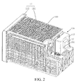
- FIG. 2 is a schematic structural view of the housing and the accommodation shell accommodating a vacuum pump in FIG. 1 .
- the airtight housing 11 includes two parts, wherein one part is a housing body 111, and the housing body 111 has an opening; the second part is a cover body 112 that a drawer door serves as, and the drawer door is located at the opening of the housing body 111 when the drawer door is closed.
- the airtight housing 11 may also have other implementation structures.
- the vacuum pump 12 is placed in an accommodation shell 13, the housing 11, specifically outer walls of the housing body 111 enclose a recessed area 11 a, the recessed area 11 a is used to accommodate the accommodation shell 13, and the accommodation shell 13 and the housing 11 are placed in the same storage chamber 101.
- the accommodation shell 13 can be partially or completely housed in the recessed area 11 a.
- the housing 11 and the accommodation shell 13 partially or wholly recessed in the recessed area 11 a enclosed by the outer walls of the housing 11 can be combined into a vacuum storage unit standard part, the standard part has good compatibility, is suitable for a certain type of refrigerating devices, can be added to refrigerating devices having different platforms/models according to requirements, and does not need to adjust layout in the existing refrigerating device, which thus increases applicability of the vacuum storage unit in the refrigerating devices having different platforms/models and is conducive to simplifying assembling of refrigerating devices having vacuum storage units, thereby helping to increase assembling efficiency.
- the vacuum pump 12 in this embodiment is housed in the accommodation shell 13, in FIG. 2 , the vacuum pump 12 is illustrated with dotted lines.
- the airtight housing 11, the vacuum pump 12 and the accommodation shell 13 form a vacuum storage unit.
- the vacuum pump 12 may also be directly fixed to the housing 11, specifically on the housing body 111, or before the housing 11 is housed in the first storage chamber 10, the vacuum pump 12 is first fixed onto an inner wall of the box-type tank defining the first storage chamber 101.
- the vacuum pump 12 may be partially or wholly housed in the housing 11, and specifically in the recessed area 11 a enclosed by the outer walls of the housing body 111.
- the airtight housing 11 and the vacuum pump 12 form a vacuum storage unit.
- the vacuum pump 12 may vibrate during evacuation, thus, when the vacuum pump 12 is directly fixed to an outer wall of the housing 11 or an inner wall of the first storage chamber 101, the vacuum pump will drive the housing 11 or a storage chamber inner tank to vibrate together, noise is greater, and after the vacuum pump 12 is housed in the accommodation shell 13, noise produced by them can be reduced through a buffer structure or the like when the accommodation shell 13 is fixed with the housing 11 (or the storage chamber inner tank).
- the recessed area 11 a is located at a junction of a rear wall and an upper wall of the housing 11, and is an unfilled angle, and in other embodiments, the recessed area 11 a may also be located on other walls.
- walls of the accommodation shell 13 and the outer walls of the housing 11 enclosing the recessed area 11 a have gaps therebetween, and the structure having gaps has the following advantages: 1) the shape of the outer walls of the housing 11 can make targeted setting according to transformation in the evacuation process of the housing 11, and 2) some buffer structures can be disposed between the accommodation shell 13 and the outer walls of the housing 11 to reduce noise of the vacuum pump 12 in the evacuation process. In other embodiments, to reduce the cost, the outer walls of the housing 11 enclosing the recessed area 11a and some walls of the accommodation shell 13 may also be shared.
- the housing 11 and the accommodation shell 13 recessed in the recessed area 11 a formed by the outer walls of the housing 11 are placed in the same storage chamber 101, and thus a wall of the accommodation shell 13 is directly provided with an opening 131, that is, exhaust of the vacuum pump 12 can be introduced into the first storage chamber 101.
- an exhaust pipe of the vacuum pump 12 may also be introduced into the first storage chamber 101, relative to the scheme of the latter, the former, in a manner of disposing an opening 131 on a wall of the accommodation shell 13, can omit installation of the exhaust pipe in the first storage chamber 101, and thus the cost is lower and the installation procedure is simple.
- the accommodation shell 13 is recessed in the recessed area 11 a enclosed by the outer walls of the housing 11, thus shortening the length of the exhaust pipe of the vacuum pump 12; in other embodiments, the accommodation shell 13 may also be placed above the housing 11 or at other corners in the first storage chamber 101, as long as the housing 11 and the accommodation shell 13 are disposed in the same storage chamber 101.
- FIG. 3 is a modular structural view of a refrigerating device in Embodiment 2.
- the structure of the refrigerating device provided in Embodiment 2 is substantially the same as that of the refrigerating device provided in Embodiment 1, and their difference lies in that: the exhaust of the vacuum pump 12 is not introduced into a first storage chamber 101 where the housing 11 is placed, but into a second storage chamber 102.
- an exhaust pipe 14 is connected between the accommodation shell 13 and the second storage chamber 102 which is disposed outside the housing 11 and the accommodation shell 13.
- the exhaust pipe 14 of an outlet end of the vacuum pump 12 in the accommodation shell 13 may also be directly introduced into the second storage chamber 102.
- the exhaust pipe 14 is preferably a soft tube
- the soft exhaust pipe 14 may be wrapped by a foaming liquid in the foaming process of the refrigerating device, and to prevent the foaming liquid from squeezing the soft tube, preferably, a hard tube is disposed outside some sections of the soft tube.
- the second storage chamber 102 may be a refrigerating chamber, a fresh-keeping chamber or a freezing chamber. As stated in Embodiment 1, the low-temperature gas discharged by the vacuum pump is directly introduced into the second storage chamber 102 which is specifically a refrigerating chamber or a fresh-keeping chamber, and energy consumption can be reduced.
- the second storage chamber 102 when the second storage chamber 102 is a freezing chamber, its temperature is lower, when a user opens the door that closes the freezing chamber, outside air enters into the freezing chamber, the temperature of the entering normal-temperature gas is lowered in the freezing chamber, while the volume is unchanged, thus the pressure is reduced, this results in that the user needs great efforts to open the door next time he/she opens the door of the freezing chamber, and discharging the low-temperature gas discharged by the vacuum pump into the freezing chamber can increase the pressure in the freezing chamber, thus facilitating the user to open the door in the case of saving efforts.
- an exhaust pipe 14 is connected between the second storage chamber 102 and the vacuum pump 12.
- FIG. 4 is a modular structural view of a refrigerating device in Embodiment 3.
- the structure of the refrigerating device provided in Embodiment 3 is substantially the same as that of the refrigerating device provided in Embodiment 1 or 2, and their difference lies in that: the exhaust of the vacuum pump 12 is not only introduced into a first storage chamber 101 where the housing 11 and the accommodation shell 13 are disposed, but also is introduced into a second storage chamber 102.
- an exhaust pipe 14 is connected between the accommodation shell 13 and the second storage chamber 102 which is disposed outside the housing 11 and the accommodation shell 13, and the exhaust pipe 14 is a Y-pipe or one-in-two-out valve.
- the Y-pipe or one-in-two-out valve introduces some exhaust into the first storage chamber 101 and some into the second storage chamber 102.
- the exhaust pipe 14 of an outlet end of the vacuum pump 12 in the accommodation shell 13 may also be directly introduced into the first storage chamber 101 and the second storage chamber 102.
- an exhaust pipe 14 is connected between the second storage chamber 102 and the vacuum pump 12, and the exhaust pipe 14 may also be a Y-pipe or one-in-two-out valve, which introduces some exhaust into the first storage chamber 101 and some into the second storage chamber 102.
- two or more other storage chambers are also included, and it is also feasible to discharge the exhaust of the vacuum pump 12 into the storage chambers through other structures.
- FIG. 5 is a modular structural view of a refrigerating device in Embodiment 4.
- the vacuum pump 12 is not placed in the accommodation shell 13 which is located in the first storage chamber 101, but located in a compressor room 15, an exhaust pipe 14 of the vacuum pump is connected to a second storage chamber 102 outside the first storage chamber 101 where the housing 11 is disposed.
- the number of the another storage chamber may also be two or more, and the exhaust pipe 14 of the vacuum pump may also be simultaneously connected to the first storage chamber 101 where the housing 11 is disposed, or only connected to the first storage chamber 101 where the housing 11 is disposed.
Landscapes
- Engineering & Computer Science (AREA)
- Chemical & Material Sciences (AREA)
- Combustion & Propulsion (AREA)
- Physics & Mathematics (AREA)
- Mechanical Engineering (AREA)
- Thermal Sciences (AREA)
- General Engineering & Computer Science (AREA)
- Cold Air Circulating Systems And Constructional Details In Refrigerators (AREA)
- Devices That Are Associated With Refrigeration Equipment (AREA)
Applications Claiming Priority (1)
| Application Number | Priority Date | Filing Date | Title |
|---|---|---|---|
| CN201420846030.XU CN204535235U (zh) | 2014-12-26 | 2014-12-26 | 制冷设备 |
Publications (1)
| Publication Number | Publication Date |
|---|---|
| EP3037762A1 true EP3037762A1 (de) | 2016-06-29 |
Family
ID=53749227
Family Applications (1)
| Application Number | Title | Priority Date | Filing Date |
|---|---|---|---|
| EP15199330.0A Withdrawn EP3037762A1 (de) | 2014-12-26 | 2015-12-10 | Kühlvorrichtung |
Country Status (2)
| Country | Link |
|---|---|
| EP (1) | EP3037762A1 (de) |
| CN (1) | CN204535235U (de) |
Cited By (1)
| Publication number | Priority date | Publication date | Assignee | Title |
|---|---|---|---|---|
| CN114061226A (zh) * | 2020-08-10 | 2022-02-18 | 海信(山东)冰箱有限公司 | 一种冰箱 |
Families Citing this family (4)
| Publication number | Priority date | Publication date | Assignee | Title |
|---|---|---|---|---|
| CN113531986A (zh) * | 2020-04-17 | 2021-10-22 | 海信(山东)冰箱有限公司 | 冰箱 |
| CN111765695A (zh) * | 2020-07-01 | 2020-10-13 | 海信(山东)冰箱有限公司 | 冰箱 |
| CN117109242B (zh) * | 2023-08-07 | 2025-11-18 | 澳柯玛股份有限公司 | 一种制冷设备负压保鲜与气压平衡装置及其控制方法 |
| CN117387271B (zh) * | 2023-09-04 | 2026-02-03 | 澳柯玛股份有限公司 | 负压制冷设备及压力控制方法 |
Citations (2)
| Publication number | Priority date | Publication date | Assignee | Title |
|---|---|---|---|---|
| JP2004251599A (ja) * | 2003-02-21 | 2004-09-09 | Toshiba Corp | 冷蔵庫 |
| JP2009036443A (ja) * | 2007-08-02 | 2009-02-19 | Hitachi Appliances Inc | 冷蔵庫 |
-
2014
- 2014-12-26 CN CN201420846030.XU patent/CN204535235U/zh not_active Expired - Fee Related
-
2015
- 2015-12-10 EP EP15199330.0A patent/EP3037762A1/de not_active Withdrawn
Patent Citations (2)
| Publication number | Priority date | Publication date | Assignee | Title |
|---|---|---|---|---|
| JP2004251599A (ja) * | 2003-02-21 | 2004-09-09 | Toshiba Corp | 冷蔵庫 |
| JP2009036443A (ja) * | 2007-08-02 | 2009-02-19 | Hitachi Appliances Inc | 冷蔵庫 |
Cited By (1)
| Publication number | Priority date | Publication date | Assignee | Title |
|---|---|---|---|---|
| CN114061226A (zh) * | 2020-08-10 | 2022-02-18 | 海信(山东)冰箱有限公司 | 一种冰箱 |
Also Published As
| Publication number | Publication date |
|---|---|
| CN204535235U (zh) | 2015-08-05 |
Similar Documents
| Publication | Publication Date | Title |
|---|---|---|
| EP3037762A1 (de) | Kühlvorrichtung | |
| US10697697B2 (en) | Vacuum insulated door structure and method for the creation thereof | |
| CN104501497B (zh) | 一种具有外接真空保鲜装置的冰箱 | |
| US10653122B2 (en) | Waterless keep-alive apparatus and refrigeration appliance provided with the waterless keep-alive apparatus | |
| WO2021208428A1 (zh) | 冰箱 | |
| CN108759244A (zh) | 具有控氧保鲜功能的冰箱 | |
| CN106568264A (zh) | 具有蓄冷功能的快速降温箱 | |
| US11828402B2 (en) | Vacuum assisted and heated auger feeder for achieving higher packing efficiency of powder insulation materials in vacuum insulated structures | |
| CN201318847Y (zh) | 内置储水盒的电冰箱 | |
| CN106593823B (zh) | 冷藏冷冻装置 | |
| CN214620253U (zh) | 一种冰箱 | |
| CN209484915U (zh) | 一种环保低温冰柜 | |
| CN102798263B (zh) | 制冷器具 | |
| CN102261783B (zh) | 制冷器具 | |
| CN114061237B (zh) | 一种真空保鲜装置及冰箱 | |
| CN102261782B (zh) | 制冷器具 | |
| CN105157310A (zh) | 一种制冷均匀的对开门大型冰箱 | |
| CN212274369U (zh) | 一种循环风冷无霜冰箱冷藏室结构 | |
| CN204313567U (zh) | 一种具有真空保鲜系统的冰箱 | |
| CN207716703U (zh) | 一种拉篮型冷柜 | |
| CN113203236A (zh) | 一种冰箱 | |
| CN204963385U (zh) | 箱胆及冷冻室上置式冰箱 | |
| CN104457093B (zh) | 多温区制冷设备 | |
| CN206291588U (zh) | 冷藏冷冻设备 | |
| CN203568172U (zh) | 真空保鲜系统以及具有该系统的制冷器具 |
Legal Events
| Date | Code | Title | Description |
|---|---|---|---|
| PUAI | Public reference made under article 153(3) epc to a published international application that has entered the european phase |
Free format text: ORIGINAL CODE: 0009012 |
|
| AK | Designated contracting states |
Kind code of ref document: A1 Designated state(s): AL AT BE BG CH CY CZ DE DK EE ES FI FR GB GR HR HU IE IS IT LI LT LU LV MC MK MT NL NO PL PT RO RS SE SI SK SM TR |
|
| AX | Request for extension of the european patent |
Extension state: BA ME |
|
| 17P | Request for examination filed |
Effective date: 20170102 |
|
| RBV | Designated contracting states (corrected) |
Designated state(s): AL AT BE BG CH CY CZ DE DK EE ES FI FR GB GR HR HU IE IS IT LI LT LU LV MC MK MT NL NO PL PT RO RS SE SI SK SM TR |
|
| 17Q | First examination report despatched |
Effective date: 20181220 |
|
| STAA | Information on the status of an ep patent application or granted ep patent |
Free format text: STATUS: THE APPLICATION IS DEEMED TO BE WITHDRAWN |
|
| 18D | Application deemed to be withdrawn |
Effective date: 20190501 |