EP3038231B1 - Steuerungsverfahren und -vorrichtung für drahtloses laden in einem drahtlosen stromübertragungssystem - Google Patents
Steuerungsverfahren und -vorrichtung für drahtloses laden in einem drahtlosen stromübertragungssystem Download PDFInfo
- Publication number
- EP3038231B1 EP3038231B1 EP14836576.0A EP14836576A EP3038231B1 EP 3038231 B1 EP3038231 B1 EP 3038231B1 EP 14836576 A EP14836576 A EP 14836576A EP 3038231 B1 EP3038231 B1 EP 3038231B1
- Authority
- EP
- European Patent Office
- Prior art keywords
- wireless charging
- wireless
- mobile terminal
- event
- function
- Prior art date
- Legal status (The legal status is an assumption and is not a legal conclusion. Google has not performed a legal analysis and makes no representation as to the accuracy of the status listed.)
- Active
Links
Images


Classifications
-
- H—ELECTRICITY
- H02—GENERATION; CONVERSION OR DISTRIBUTION OF ELECTRIC POWER
- H02J—ELECTRIC POWER NETWORKS; CIRCUIT ARRANGEMENTS OR SYSTEMS FOR SUPPLYING OR DISTRIBUTING ELECTRIC POWER; SYSTEMS FOR STORING ELECTRIC ENERGY
- H02J50/00—Circuit arrangements or systems for wireless supply or distribution of electric power
- H02J50/10—Circuit arrangements or systems for wireless supply or distribution of electric power using inductive coupling
- H02J50/12—Circuit arrangements or systems for wireless supply or distribution of electric power using inductive coupling of the resonant type
-
- G—PHYSICS
- G06—COMPUTING OR CALCULATING; COUNTING
- G06F—ELECTRIC DIGITAL DATA PROCESSING
- G06F3/00—Input arrangements for transferring data to be processed into a form capable of being handled by the computer; Output arrangements for transferring data from processing unit to output unit, e.g. interface arrangements
- G06F3/01—Input arrangements or combined input and output arrangements for interaction between user and computer
- G06F3/03—Arrangements for converting the position or the displacement of a member into a coded form
- G06F3/041—Digitisers, e.g. for touch screens or touch pads, characterised by the transducing means
-
- H—ELECTRICITY
- H02—GENERATION; CONVERSION OR DISTRIBUTION OF ELECTRIC POWER
- H02J—ELECTRIC POWER NETWORKS; CIRCUIT ARRANGEMENTS OR SYSTEMS FOR SUPPLYING OR DISTRIBUTING ELECTRIC POWER; SYSTEMS FOR STORING ELECTRIC ENERGY
- H02J50/00—Circuit arrangements or systems for wireless supply or distribution of electric power
- H02J50/60—Circuit arrangements or systems for wireless supply or distribution of electric power responsive to the presence of foreign objects, e.g. detection of living beings
-
- H—ELECTRICITY
- H02—GENERATION; CONVERSION OR DISTRIBUTION OF ELECTRIC POWER
- H02J—ELECTRIC POWER NETWORKS; CIRCUIT ARRANGEMENTS OR SYSTEMS FOR SUPPLYING OR DISTRIBUTING ELECTRIC POWER; SYSTEMS FOR STORING ELECTRIC ENERGY
- H02J50/00—Circuit arrangements or systems for wireless supply or distribution of electric power
- H02J50/80—Circuit arrangements or systems for wireless supply or distribution of electric power involving the exchange of data, concerning supply or distribution of electric power, between transmitting devices and receiving devices
-
- H—ELECTRICITY
- H02—GENERATION; CONVERSION OR DISTRIBUTION OF ELECTRIC POWER
- H02J—ELECTRIC POWER NETWORKS; CIRCUIT ARRANGEMENTS OR SYSTEMS FOR SUPPLYING OR DISTRIBUTING ELECTRIC POWER; SYSTEMS FOR STORING ELECTRIC ENERGY
- H02J7/00—Circuit arrangements for charging or discharging batteries or for supplying loads from batteries
- H02J7/90—Regulation of charging or discharging current or voltage
-
- H—ELECTRICITY
- H02—GENERATION; CONVERSION OR DISTRIBUTION OF ELECTRIC POWER
- H02J—ELECTRIC POWER NETWORKS; CIRCUIT ARRANGEMENTS OR SYSTEMS FOR SUPPLYING OR DISTRIBUTING ELECTRIC POWER; SYSTEMS FOR STORING ELECTRIC ENERGY
- H02J2105/00—Networks for supplying or distributing electric power characterised by their spatial reach or by the load
- H02J2105/40—Networks for supplying or distributing electric power characterised by their spatial reach or by the load characterised by the loads connecting to the networks or being supplied by the networks
- H02J2105/44—Portable electronic devices
-
- H—ELECTRICITY
- H02—GENERATION; CONVERSION OR DISTRIBUTION OF ELECTRIC POWER
- H02J—ELECTRIC POWER NETWORKS; CIRCUIT ARRANGEMENTS OR SYSTEMS FOR SUPPLYING OR DISTRIBUTING ELECTRIC POWER; SYSTEMS FOR STORING ELECTRIC ENERGY
- H02J7/00—Circuit arrangements for charging or discharging batteries or for supplying loads from batteries
- H02J7/40—Circuit arrangements for charging or discharging batteries or for supplying loads from batteries characterised by the exchange of charge or discharge related data
- H02J7/47—Arrangements for checking compatibility or authentication between one component, e.g. a battery or a battery charger, and another component, e.g. a power source
Definitions
- the present disclosure relates to a wireless power transmission (transmission/reception) technology (Wireless Power Technology: WPT or Wireless Energy Transfer) applied to a wireless charging technology and, for example, to a method and apparatus for controlling wireless charging according to a user environment.
- a wireless power transmission (transmission/reception) technology Wireless Power Technology: WPT or Wireless Energy Transfer
- a mobile terminal such as a mobile phone, a Personal Digital Assistant (PDA) or the like, is driven by a rechargeable battery owing to the nature of the terminal, and electric energy is supplied to the battery of the mobile terminal by using a separate charging apparatus in order to charge the battery.
- the charging apparatus and the battery have separate contact terminals on the outside thereof, respectively and are electrically connected to each other by mutual contact between the contact terminals.
- the contact terminals protrude outwardly, and thus are easily contaminated by foreign substances. As a result, battery charging is not correctly performed.
- a wireless charging or contactless charging technology can solve such problems.
- Such a wireless charging technology uses the wireless power transmission technology and the wireless power transmission technology refers to a technology that can transmit power without using a wire.
- a power transmission method using electromagnetic induction corresponds to a scheme of transmitting power between a first coil of a transmission apparatus and a second coil of a reception apparatus.
- the resonance scheme corresponds to a scheme using a frequency resonance technology between the transmission apparatus and the reception apparatus, using a predetermined resonance frequency, and has an advantage of enabling a relatively-remote wireless power transmission, compared with the electromagnetic induction scheme.
- the above-mentioned wireless charging technology is a very promising field thanks to the rapid increase of mobile terminal technologies and the extensive supply of various application products, but has problems relating to frequency allocation, an influence on a human body and the like. For example, as power transmission capacity becomes larger and a transmission distance becomes further, it is more likely that a human body is harmfully affected by an exposure to an electromagnetic wave. Further, when other functions of a mobile terminal are used while wireless charging is being performing, a malfunction of the mobile terminal or inconvenience in a use thereof may be caused due to a wireless charging electromagnetic wave.
- US 2013/082651 A1 discusses methods for providing wireless charging.
- WO 2009/131990 A2 discusses a device which is powered wirelessly.
- KR 2012 0009628 A discusses a contactless charging apparatus of a mobile terminal. Further relevant prior art is established by: US 2004/084965 A1 (WELCHES RICHARD SHAUN [US] ET AL) 6 May 2004 (2004-05-06) and EP 1 670 115 A1 (META SYSTEM SPA [IT]) 14 June 2006 (2006-06-14)
- the content of the present disclosure provides a wireless charging control method and apparatus that can reduce an influence of a wireless charging electromagnetic wave on a human body while a user's apparatus including a mobile terminal is being wireless charged, can reduce malfunctions, and can further increase user convenience.
- a wireless charging control method in an apparatus having a wireless power reception module comprising: sensing an event in a wireless charging mode; determining whether the sensed event corresponds to a wireless charging indirect-associated event,; when the sensed event corresponds to the wireless charging indirect-associated event, identifying the wireless charging operation corresponding to the event; and controlling wireless charging according to the identified wireless charging operation.
- the wireless-charging indirect-associated event is a call event.
- a mobile terminal having a wireless charging function comprises: a mobile communication unit that performs wireless signal transmitting and receiving; a touch screen that performs a display function relating to output information and an input function; a wireless power reception module that receives charging power provided from an external wireless power transmission apparatus; a power supply unit that receives charging power provided from the wireless power reception module and generates internal operation power of the corresponding mobile terminal; and a control unit that controls an operation of the corresponding mobile terminal as a whole by collectively controlling the respective functional units and that, when a wireless-charging indirect-associated event occurs while a wireless charging operation is being performed, controls the wireless charging operation according to the occurred event.
- the wireless-charging indirect-associated event corresponds to a call event.
- a wireless charging control method in a wireless power transmission system can properly control, for example, a wireless charging operation according to an operation of a user apparatus in a resonance type wireless charging environment, thereby reducing heat generation of a terminal and an influence on a human body.
- the wireless charging control method can prevent functional malfunctions, including the reduction of input sensing malfunction in an electronic pen use or touch input environment. Further, the wireless charging control method can provide user convenience by the automatic conversion of speaker/receiver call modes.
- FIG. 1 is an overall block diagram of a resonance-type wireless power transmission/reception system to which an embodiment of the present invention is applied.
- the resonance-type wireless power transmission/reception system includes, for example, a wireless power transmission apparatus 1 corresponding to a source apparatus that supplies charging power and, for example, a wireless power reception module 12, which may be included in a mobile terminal, corresponding to a target apparatus that is supplied with wireless power.
- the wireless power transmission apparatus 1 includes: a signal generating unit 110 that includes a Voltage Control Oscillator (VCO), etc. and generates a signal of a predetermined frequency, for example, a resonance frequency of 6.78 MHz; an amplification unit 112 that includes an amplifier, etc. and amplifies the signal, generated by the signal generating unit 110, into a high output power signal; a resonance signal generating unit 114 that includes a resonator, etc.
- VCO Voltage Control Oscillator
- a wireless resonance signal of 6.78 MHz according to the high output power signal generated by the amplification unit 112; a voltage/current detecting unit 116 that detects a (peak level of) voltage and current of the wireless resonance signal generated by the resonance signal generating unit 114; and a control unit 118 that collectively controls a wireless power transmission operation of the corresponding wireless power transmission apparatus 1, monitors a current and voltage of a resonance signal wirelessly transmitted according to the current and voltage detected by the voltage/current detecting unit 116, and controls operations of the signal generating unit 110 and the amplification unit 112 so that the current and voltage maintain a value which is predetermined to be in the normal range.
- the wireless power transmission apparatus 1 includes: a sensor unit 117 that includes an object sensing sensor, etc. in order to sense that the reception module 12 is placed thereon and provides a sensing signal to the control unit 118; and a local area communication unit 119 configured by applying one selected from among various wireless local communication schemes, for example, Zigbee, in order to communicate with the reception module 12 in relation to a wireless power transmission operation under a control of the control unit 118.
- a sensor unit 117 that includes an object sensing sensor, etc. in order to sense that the reception module 12 is placed thereon and provides a sensing signal to the control unit 118
- a local area communication unit 119 configured by applying one selected from among various wireless local communication schemes, for example, Zigbee, in order to communicate with the reception module 12 in relation to a wireless power transmission operation under a control of the control unit 118.
- the wireless power reception module 12 includes: a resonance signal receiving unit 124 that includes a resonator, etc. and receives a wireless resonance signal transmitted by the resonance signal generating unit 114 of the wireless power transmission apparatus 1; a rectifier 122 that rectifies an alternating current (AC)-type power, which is received by the resonance signal receiving unit 124, to a direct current (DC); a smoothing unit 121 that smoothes the DC power rectified by the rectifier 122; a constant voltage generating unit 120 that converts power output by the smoothing unit 121 into operation power (for example, +5V) desired by a mobile terminal, etc.
- a resonance signal receiving unit 124 that includes a resonator, etc. and receives a wireless resonance signal transmitted by the resonance signal generating unit 114 of the wireless power transmission apparatus 1
- a rectifier 122 that rectifies an alternating current (AC)-type power, which is received by the resonance signal receiving unit 124, to a direct current (DC)
- a smoothing unit 121 that
- an overvoltage protecting unit 125 that, in an overvoltage protecting operation, is driven by a driving unit 127 to detune a resonance frequency of a resonator of the resonance signal receiving unit 124, thereby reducing reception power; the driving unit 127 that, in the overvoltage protecting operation, drives the overvoltage protecting unit 125 according to a control signal; a voltage detecting unit 126 that detects the input voltage of the constant voltage generating unit 120; and a (resonance) control unit 128 that collectively controls a wireless power reception operation of the corresponding wireless power reception module 12, determines whether a voltage is an overvoltage according to a detection signal of the voltage detecting unit 126, and, when the voltage is determined to be an overvoltage, outputs a control signal for driving the overvoltage protecting unit 125 to the driving unit 127 for the overvoltage protection operation, the control unit 128 being implemented by an MCU or the like.
- the wireless power reception module 120 may further include: a local area communication unit 129 that is configured by applying one selected from among various wireless local area communication schemes in order to communicate with the wireless power transmission apparatus 1 under a control of the control unit 128 in relation to a wireless power reception operation; and a waveform stabilization unit (not illustrated) that includes an LC circuit, and stabilizes and outputs a DC waveform output by the constant voltage generating unit 120.
- a local area communication unit 129 that is configured by applying one selected from among various wireless local area communication schemes in order to communicate with the wireless power transmission apparatus 1 under a control of the control unit 128 in relation to a wireless power reception operation
- a waveform stabilization unit (not illustrated) that includes an LC circuit, and stabilizes and outputs a DC waveform output by the constant voltage generating unit 120.
- FIG. 2 is an overall block diagram of a mobile terminal having a wireless power reception module in FIG. 1 .
- a mobile terminal to which an embodiment of the present invention is applied, has the wireless power reception module 12, and, in addition, may be configured including a control unit 10, a storage unit 11, a mobile communication unit 14, a local area communication unit 13, an audio processing unit 15, a touch screen 16, a key input unit 17, and a sensor unit 18.
- the mobile terminal illustrated in FIG. 1 discloses, as an example, a structure corresponding to a smart phone, a mobile phone, or the like.
- a mobile terminal may include various apparatuses, such as a Potable Multimedia Player (PMP), a PDA, an MP3 player, a tablet PC, a personal navigation apparatus, a portable game apparatus, and the like.
- PMP Potable Multimedia Player
- PDA PDA
- MP3 player MP3 player
- tablet PC a personal navigation apparatus
- portable game apparatus a portable game apparatus
- the touch screen 16 may include a display panel 160, which performs a display function relating to output information output by a mobile terminal, and an input sensing panel 162, which performs various input functions by a user.
- the display panel 160 may be generally configured by a Liquid Crystal Display (LCD) screen or an Organic Light Emitting Diode (OLED) (e.g., PMOLED or AMOLED) screen and may be implemented integrally with the input sensing panel 162 structurally.
- the display panel 160 may display various screens according to various operation states, menu states, application executions and services, etc. of the corresponding mobile terminal.
- the input sensing panel 162 may be implemented by at least one panel that may sense various inputs, such as a single or multi-touch input, a drag input, a writing input, a drawing input, and the like provided by a user using various objects such as a finger, an electronic pen (not illustrated), and the like.
- the input sensing panel 162 may be implemented using one panel which can sense both a finger input and an electronic pen input or may be implemented using two panels such as a hand sensing panel 162b which can sense the finger input and a pen sensing panel 162a which can sense the electronic pen input.
- the hand sensing panel 162b may sense a finger touch (contact) input or a finger proximity (noncontact) input.
- the hand sensing panel 162b may have a form of, for example, a touch film, a touch sheet, a touch pad, etc.
- the hand sensing panel 162b senses a touch input and outputs a touch event value corresponding to a sensed touch signal. At this time, information corresponding to the sensed touch signal may be displayed on the display panel 160.
- the hand sensing panel 162b may receive an operation signal by the touch input of the user through various input means.
- the hand sensing panel 162b may sense a touch input including a user's body (for example, a finger) and a physical tool.
- the hand sensing panel 162b may be a capacitive type touch panel.
- the hand sensing panel 162b is configured by coating both sides of glass with a thin metal conductive material (for example, an Indium Tin Oxide (ITO) film or the like) to allow a current to flow on a surface of the glass and thus is coated with a dielectric that can store a charge.
- ITO Indium Tin Oxide
- a surface of the hand sensing panel 162b is touched by an object, a predetermined amount of the charge is moved to a contact position by static electricity, and the hand sensing panel 162b recognizes the changed amount of the current according to the movement of the charge to sense the touched position and tracks a touch event.
- the touch event generated on the hand sensing panel 162b may be generated mainly by a finger of a person but may be generated by another object which makes a change in capacitance, for example, a conductive object which makes the change in capacitance.
- the pen sensing panel 162 senses a proximity input or contact input of the electronic pen according to the use of the electronic pen (for example, a stylus pen or a digitizer pen) and outputs a sensed electronic pen proximity event or electronic pen contact event.
- the pen sensing panel 162a may be implemented in an EMR scheme and may sense a touch or proximity input according to a change in the intensity of an electromagnetic field by the proximity or touch of a pen.
- the pen sensing panel 162a may include: an electromagnetic induction coil sensor (not illustrated) having a grid structure in which a plurality of loop coils are arranged in a predetermined first direction and a second direction crossing the first direction; and an electronic signal processing unit (not illustrated) sequentially providing an alternative current signal having a predetermined frequency to each of the loop coils of the electromagnetic induction coil sensor.
- an electronic pen which has a resonance circuit embedded therein, is near a loop coil of the pen sensing panel 162a
- a magnetic field transmitted from the corresponding loop coil generates a current, which is based on mutual electromagnetic induction, in the resonance circuit within the electronic pen.
- an induced magnetic field is generated from the coil included in the resonance circuit within the electronic pen.
- the pen sensing panel 162a detects the induced magnetic field from the loop coil in a signal reception state and senses a proximity position or touch position of the pen. Through the pen sensing panel 162a, the approach or touch of an object can be sensed, if the object can generate the current based on the electromagnetic induction.
- the pen sensing panel 162a may have an activation state according to generation of a particular event or by default. Further, the pen sensing panel 162a may be arranged with a predetermined area, for example, an area to cover a display area of the display panel 160 below the display panel 160.
- the mobile communication unit 14 is an element which may be included when the corresponding mobile terminal supports a mobile communication function.
- the mobile communication unit may include an antenna, an RF unit, and a modem in order to perform a wireless signal transmitting/receiving and processing operation for the mobile communication function.
- the RF unit includes an RF transmitter that up-converts and amplifies a frequency of a transmitted signal, and an RF receiver that low-noise amplifies a received signal and down-converts a frequency.
- the modem includes a transmitter that codes and modulates a signal to be transmitted and a receiver that decodes and demodulates a signal received by the RF unit.
- the mobile communication unit 14 may perform a particular function of the mobile terminal, which is required to have a communication function, for example, a chatting function, a message transmission/reception function, a call function, or the like.
- the local area communication unit 13 includes a wireless LAN module or a local area communication module, such as Wi-Fi Direct, Near Field Communication (NFC), Bluetooth, Zigbee, or the like, to be connected to the wireless Internet at a place in which a wireless Access Point (AP) is installed, or to wirelessly perform a local area communication operation with peripheral apparatuses.
- a Radio Frequency Identification RFID
- IrDA infrared Data Association
- UWB Ultra Wideband
- the sensor unit 18 may include a proximity sensor 182, a motion sensor 184, and a temperature sensor 186.
- the proximity sensor 182 is a sensor that detects, without a mechanical contact, whether an object approaches a mobile terminal or exists in the vicinity of the mobile terminal, and detects a proximate object by using a change in an AC magnetic field or a change in a static magnetic field or by using a change rate of capacitance or the like.
- the motion sensor 184 senses the position or motion of a mobile terminal by using an acceleration sensor, a gyro sensor, etc.
- the acceleration sensor which can be used in the motion sensor 243, is an element that converts an acceleration change of any one direction to an electric signal.
- the gyro sensor is a sensor that measures the angular velocity of a mobile terminal which performs a rotation motion, and may sense a rotated angle for each reference direction.
- the gyro sensor may sense a rotation angle of each of axes in three directions, that is, an azimuth, a pitch, and a roll, with reference to the axes in three directions.
- the sensor unit 18 may include a pressure sensor for sensing a pressure applied to the corresponding mobile terminal, an illumination sensor for sensing illumination, or the like.
- the temperature sensor 186 is a sensor for sensing an internal/external temperature of the mobile terminal, and sensors, which have various types and structures, for sensing a temperature may be adopted.
- the key input unit 17 includes a key, which is mechanically included in an outer housing, for manipulating multiple operations and receives a user's manipulation. Such a key may include a side key, a separately provided touch pad, etc. Further, the key input unit 17 may include a button key for turning on or turning off a mobile terminal, a home key that supports a return to a basic screen supported by the mobile terminal, etc.
- the audio processing unit 15 includes a speaker SPK and a receiver RCV for outputting an audio signal of the mobile terminal, and a microphone MIC for collecting the audio signal.
- the audio processing unit 130 may include a voice codec, which processes an audio signal input and output through the speaker and the microphone, and when a phone call according to a mobile communication function is executed, the audio processing unit 15 receives a voice of a user or outputs an audible sound to the user, and outputs processing sounds corresponding to various operations or sounds corresponding to various digital audio contents, video contents, or the like.
- the receiver RCV is a low output power speaker through which a voice signal received during a call is output, a voice during a call is output, and the speaker SPK outputs the voice signal or audio signal amplified through a predetermined amplification means.
- the voice is output through the receiver, and, when a music playing mode or a speakerphone mode is configured, the voice and the audio signal are output through the speaker.
- the audio processing unit 15 includes an internal switching means to switch the voice to be output through one of the receiver and the speaker according to a control signal of the control unit 10.
- the receiver may be properly formed at the front upper part, at which the touch screen 16 is formed, of a mobile terminal, and the speaker may be properly formed at the rear surface of the mobile terminal.
- the present embodiment describes an example in which the audio processing unit 15 includes both a speaker and a receiver, but the audio processing unit 15 may be implemented to include one speaker but not both the speaker and the receiver and operate in a speaker mode or a receiver mode through a change in the amplification rate.
- the storage unit 11 is configured to store various programs and data required for a mobile terminal operation.
- the storage unit 11 may include a program memory and a data memory for storing various application programs, related contents, data relating to operation processing, etc.
- the program memory stores a program for controlling general operations of the mobile terminal.
- the storage unit 11 prestores an operation program and related data for a wireless charging control operation in a wireless power transmission system according to the features of the present invention.
- the control unit 10 may collectively control the respective functional units to control overall operations of the mobile terminal, and may switch and control an operation of the mobile terminal according to a user input which is input through the touch screen 16 or the key input unit 17. Further, the control unit 10 performs a wireless charging control operation in the wireless power transmission system according the features of the present invention.
- the control unit 10 adjusts an operation environment of predetermined functions, which are related to wireless charging, for example, the performing of a call and the processing of input sensing, during a wireless charging operation according to the features of the present invention. A detailed operation of the control unit 10 according to the features of the present invention will be described through an embodiment of the present invention described below.
- the power supply unit 19 has a battery for charging, receives charging power, which is provided by the wireless power reception module 12, to charge the battery for charging, and supplies operation power to internal functional units.
- the wireless power reception module 12 may be configured as illustrated in FIG. 1 .
- the control unit 128 of the wireless power reception module 12 is configured to be distinguished from the control unit 10 of the mobile terminal.
- the control unit 10 of the mobile terminal may be implemented to play, in parallel, a role of the control unit 128 of the wireless power reception module 12.
- a mobile terminal may be implemented by including configuration units as described above.
- the mobile terminal may basically include or additionally include functional units, which are applied to the current mobile communication terminal, such as a GPS unit, a vibration motor, a camera module, and the like.
- a general wireless charging operation is described. For example, when a call is received during wireless charging and a user performs a call connection operation, a call operation starts. In this case, the call is basically performed in a receiver call mode. At this time, even when the user puts the mobile terminal against his/her ear and starts a call, a voice call is performed in a situation in which the mobile terminal is continuously charged, since the resonance scheme enables charging even at a distance of 1-2 m. Since a charging pad of the wireless power transmission apparatus 11 continues to transmit transmission power to the wireless power reception module 12, a safety problem relating to a situation in which the mobile terminal is placed around the user's head is likely to occur. Further, since charging is being performed, more heat is generated than an idle state in which charging is not performed or a state in which other functions are used. Therefore, inconvenience due to heat is added while making a call.
- the mobile terminal is generally put on the charging pad, and thus charging pad structures having various designs and uses are expected to be developed.
- a stand-type charging pad enables a user to watch a video while performing wireless charging.
- the user when the user desires to perform a call operation while wirelessly charging the mobile terminal in a state in which the mobile terminal is put on the charging pad or while watching a video, the user normally makes a call using a speaker mode.
- the user currently, there is an inconvenience in that the user must perform a call connection/rejection operation and then perform, again, a separate menu selection operation to make a change into a speaker call mode.
- wireless charging has a considerable influence on normal operations of the mobile terminal while the mobile terminal is being charged. Therefore, it is necessary to adjust a condition for performing a normal function of the mobile terminal so that they are more optimized during a wireless charging operation. For example, whether wireless charging is being performed may also have an influence on performing other functions of the mobile terminal, in addition to the above-described call operation.
- a situation in a terminal which supports an electronic pen function, as one among such functions, may be provided as an example.
- Current smart phones include terminals which implement various input schemes and applications by applying an electronic pen technology. Under a wireless charging environment, a change occurs in the recognition rate of the electronic pen. Therefore it is necessary to distinguish between a wireless charging situation and a non-wireless charging situation to control an electronic pen input.
- the electronic pen technology is configured to generate a resonance on an electronic pen resonance circuit by forming an EM Field and then measure a current by the resonance from an electronic pen. Therefore, when wireless charging is being performed in a terminal, a change may occur in the electronic pen recognition due to charging TX POWER.
- an input sensing threshold value of the electronic pen is properly changed and adjusted. In other words, through the comparison with a reference threshold value, an input sensing threshold value in the case of wireless charging is adjusted so as to compensate for the amount which is offset in the case of wireless charging.
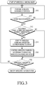
- FIG. 3 is a flowchart of a wireless charging control operation according to an embodiment of the present invention and the control operation may be performed under the control of the control unit 10 of the mobile terminal, illustrated in FIG. 2 .
- a wireless charging operation is, first, performed in step 210.
- the wireless power transmission apparatus senses the mobile terminal pickup through a sensor unit. Further, the mobile terminal may also be sensed through local area wireless communication.
- the wireless power transmission apparatus determines the mobile terminal to be a wireless chargeable charger through authentication by ID exchange, performs a power transmission negotiation, and then starts power transmission, thereby starting a wireless charging mode between the wireless power transmission apparatus and a wireless power reception apparatus (i.e. a mobile terminal).
- a wireless power transmission step is performed according to a general step.
- the wireless power reception module 12 notifies the control unit 10 of the mobile terminal of the start of the wireless power transmission, and the control unit 10 indicates a wireless charging state flag value showing that wireless charging is being performing and stores the value in the storage unit 11.
- step 210 whether an event occurs during a wireless charging operation is continuously sensed. When the event occurs, the occurrence of the event is determined in step 211 and the process thereafter proceeds to step 212.
- step 212 whether the occurred event corresponds to an event (wireless-charging indirect-associated event) relating to a predetermined wireless-charging indirect-associated function is determined.
- the process proceeds to step 214.
- the control unit determines whether the non-occurrence of the event corresponds to a wireless charging termination condition, as in step 220.
- the wireless charging operation in step 210 is continuously performed. Examples of the wireless charging termination condition may include a case where a mobile terminal is at a distance at which the mobile terminal cannot be wirelessly charged and a case where the mobile terminal is confirmed to be in a fully charged state.
- step 214 to which the process proceeds when the wireless-charging indirect-associated event is confirmed to have occurred in step 212, a wireless charging operation corresponding to the occurred event is identified. Thereafter, in step 216, the control unit controls a wireless charging operation according to the wireless charging operation and proceeds to the step 220.
- the wireless-charging indirect-associated event in step 212 refers to an event relating to wireless-charging indirect-associated functions, which are predetermined to be indirectly associated with a wireless charging operation, among various non-wireless charging-related events which are not directly associated with the wireless charging.
- Examples of the wireless-charging indirect-associated event may include a call event, a user input event, a temperature change event, etc.
- the present disclosure configures, as wireless charging indirect-related functions, some functions among functions, which are directly associated with wireless charging, such as operations related to the start and end of a wireless charging operation and signal transmission/reception for the wireless power transmission apparatus 1 and a wireless charging control, and among various non-wireless changing-related applications or functions, which are not directly associated with wireless charging, in consideration of an influence of an electromagnetic wave on a human body or an influence on the corresponding function according to a wireless charging operation, wherein the some functions are pre-classified as affecting a wireless charging operation or as indirectly affected by the wireless charging operation, according to the present disclosure.
- the present disclosure configures a more optimized wireless charging control to be needed for the some functions.
- the wireless charging operation in step 214 corresponds to at least one of a wireless charging (temporary) stop, a charging standby, and a charging current reduction/increase, and, in step 216, the control unit controls the wireless charging operation according to such an identified wireless charging operation.
- the operation of controlling wireless charging may correspond to one of a charging stop and a charging standby.
- the control unit when a call event occurs while wireless charging is being performed, the control unit (temporarily) stops the charging or performs a charging standby operation in order to reduce an influence of a wireless charging electromagnetic wave on a human body.
- the above-described call event may include not only a call event according to the speaker call mode but also a receiver call mode in a case of human body proximity. In the case of the receiver call mode, the control unit is configured to stop a wireless charging operation or to be on charging standby.
- the wireless-charging indirect-associated event corresponds to a user input event, such as a finger touch input, a finger proximity input, an electronic pen touch input, an electronic pen proximity input, or the like
- the wireless charging control operation may correspond to one of a charging stop, a charging standby, and a charging current reduction.
- the above-described wireless-charging indirect-associated event may be a temperature change event.
- the control unit may be configured to consider the temperature rise as a temperature change by a human body contact (or access) and then perform one of a wireless charging stop, a charging standby, and a charging current reduction.
- the control unit may be configured to consider the mobile terminal to be in an abnormal charging state and to perform an operation for (temporarily) stopping the wireless charging operation.
- an operation of controlling a wireless charging operation according to the identified wireless charging operation may include an operation of generating a wireless charging control signal relating to an operation of a wireless charging stop, a charging standby, or a charging current reduction, and transmitting the generated signal to a wireless power transmission apparatus (reference numeral 1 in FIG. 1 ). Therefore, the corresponding wireless power transmission apparatus performs an operation of the wireless charging stop, the charging standby, or the charging current reduction.
- the control unit may be configured to control the corresponding wireless power reception module 12 to perform an operation such as a wireless charging stop, a charging standby, etc.
- FIG. 4 is a flowchart of a wireless charging control operation according to another embodiment of the present invention and the wireless charging control operation may be performed under the control of the control unit 10 of the mobile terminal, illustrated in FIG. 2 .
- the wireless charging control operation may be performed under the control of the control unit 10 of the mobile terminal, illustrated in FIG. 2 .
- FIG. 4 when a wireless charging mode starts, an operation environment of predetermined wireless charging-associated functions is, first, adjusted in step 302.
- the wireless power transmission apparatus senses the mobile terminal pickup through a sensor unit.
- the mobile terminal may also be sensed through local area wireless communication.
- the wireless power transmission apparatus determines the mobile terminal to be a wireless chargeable charger through authentication by ID exchange, performs a power transmission negotiation, and then starts power transmission, thereby starting a wireless charging mode between the wireless power transmission apparatus and a wireless power reception apparatus (i.e. a mobile terminal).
- a wireless power transmission step is performed according to a general step.
- the wireless power reception module 12 notifies the control unit 10 of the mobile terminal of the start of the wireless power transmission, and the control unit 10 indicates a wireless charging state flag value corresponding to wireless charging state and stores the value to the storage unit 11.
- the adjusting of the operation environment of the wireless charging-associated functions is, for example, to give priority to a speaker call mode in the case of a call operation and to change an input sensing condition in an input sensing panel(s) to a wireless charging mode sensing condition. More specifically, when the wireless charging state flag value stored in the storage unit, the wireless charging state value, indicates that wireless charging is being performed, the control unit of the mobile terminal changes a priority from the existing receiver call mode priority to a speaker call mode priority. Further, an input sensing threshold value of an electronic pen is adjusted into a predetermined input sensing threshold value at the time of wireless charging.
- step 310 a wireless charging operation is performed.
- the control unit continuously senses whether an event occurs while such a wireless charging operation is being performed. When the event occurs, the control unit determined the occurrence of the event in step 311 and then proceeds to step 312.
- step 312 the control unit determines whether the occurred event corresponds to an event relating to predetermined wireless-charging indirect-associated functions, that is, a wireless-charging indirect-associated event (for example, a call event or an input sensing event), and thereafter proceeds to step 320 or step 330.
- a wireless-charging indirect-associated event for example, a call event or an input sensing event
- the control unit determines whether the non-occurrence of the event corresponds to a wireless charging termination condition, as in step 340.
- the wireless charging operation of step 310 is continuously performed. Examples of the wireless charging completion condition may include a case where a mobile terminal is at a distance at which the mobile terminal cannot be wirelessly charged or a case where the mobile terminal is confirmed to be in a fully charged state.
- step 312 determines whether the wireless-charging indirect-associated event is, in step 312, determined to have occurred and the corresponding event corresponds to a call event.
- the control unit proceeds to step 320 and performs a call operation in the speaker call mode to which a priority is currently given.
- the control unit switches the speaker call mode into the receiver call mode and (temporarily) stops a charging operation, according to the feature of the present invention.
- the control unit confirms the termination in step 329 and then proceeds to step 340 to determine whether the wireless charging has been terminated.
- the control unit returns to step 310 and repeats the operation.
- step 312 when the wireless-charging indirect-associated event is determined to have occurred and the corresponding event corresponds to an input sensing event, the control unit proceeds to step 330 to perform an input sensing processing operation.
- the control unit (temporarily) stops the charging operation, according to a feature of the present invention.
- the control unit confirms the termination in step 339 and then proceeds to step 340 to determine whether the wireless charging has ended.
- the control unit returns to step 310 and repeats the operation.
- FIG. 5 is a detailed flowchart of an operation of performing a call in FIG. 4 and illustrates an operation of performing a call in the case of the occurrence of a call termination event.
- the control unit notifies, through a display unit, that a call has been received, and displays a call connection/rejection selection menu.
- the control unit may notify, through a screen display or other methods, that since wireless charging is currently being performed, a call path is configured as the speaker call mode priority.
- control unit When a user operates a call connection/rejection selection, the control unit identifies the selection operation in step 322. When the user has operated a call connection selection, the process proceeds to step 323, and when the user has operated a call rejection selection, the call ends.
- step 323 a call is made in a speaker call mode.
- step 323 when a terminal pick-up and a human body proximity state are recognized, the terminal pick-up and the human body proximity state are confirmed in step 324 and then the process proceeds to step 325. Otherwise, a call is made in the speaker call mode in step 323. Of course, step 323 ends when the call ends.
- the control unit activates a sensor unit and senses an input change value of the sensor unit.
- the activated sensor unit senses the motion of a terminal and the proximity or non-proximity thereof to a user.
- the user has selected a call connection selection menu item during wireless charging to enter a speaker mode which corresponds to a high-priority call mode.
- the speaker mode is selected by priority during wireless charging.
- the user may desire to make a call in a receiver call mode according to a surrounding environment or as necessary.
- the sensor unit transfers, to the control unit, data which is sensed through a motion sensing sensor, such as a acceleration sensor, and a distance sensing method, such as a proximity sensor.
- the control unit acquires information on the motion and the proximity or non-proximity through the data transferred from the sensor unit.
- the control unit determines, on the basis of such information, a situation in which the user has put the mobile terminal against his/her ear by moving the mobile terminal. In other words, when a call is received in a wireless power transmission state and the user puts a mobile terminal against his/her ear by moving the mobile terminal after selecting a call selection menu, the control unit determines such an operation through the sensor unit.
- the control unit thereafter proceeds to step 325 and requests a wireless power transmission apparatus to stop transmitting transmission power to the corresponding mobile terminal, through inband wireless communication or outband wireless communication. Therefore, the wireless power transmission apparatus stops a wireless charging operation for the mobile terminal according to the above-described request.
- the wireless power transmission apparatus which receives the request of the mobile terminal, confirms identification (ID) information relating to the corresponding mobile terminal, stops power transmission for the corresponding ID information, and then is on standby for a predetermined time.
- ID identification
- the standby mode is not an essential requirement, and power transmission may, as an embodiment, be immediately stopped.
- the control unit controls the wireless power reception module of the corresponding mobile terminal itself to turn off the wireless charging operation.
- the wireless power reception module controls a switch on a wireless charging PATH according to a control of the control unit, or disables wireless charging through a required method.
- a call is made in the receiver call mode.
- the control unit senses, through the sensor unit, an operation in which the user desires the receiver call mode, the control unit stops charging as described above, and changes the speaker call mode, which the user has entered according to charging condition priority, to the receiver call mode.
- the control unit controls a voice, which is received through a wireless transmission/reception unit, to be output to a receiver through an audio processing unit. Further, the control unit changes the sensitivity of a microphone, thereby changing the user voice input level to be suitable for the receiver call mode.
- the mobile terminal stops wireless charging through stopping power transmission from a charging pad and stopping the performance of charging by the terminal according to the user's operation which desires the receiver call mode.
- a concern about an influence on a human body, which is related to wireless power transmission during a call is reduced and heat generation of the terminal is also reduced in a human body proximity condition.
- such an operation may be more carefully controlled by monitoring the current battery level of a mobile terminal. When the battery level is determined not to satisfy the minimum call time, the control unit may allow the terminal to notify a user that charging must be maintained or to adaptively determine whether to charge according to the battery level and a call mode state.
- step 327 when a selection operation for the speaker call mode is performed, the control unit confirms the selection operation in step 327 and then proceeds to step 328. Otherwise, a call is performed in the receiver call mode in step 326. Of course, step 326 ends when the call ends.
- the control unit confirms data of the sensor unit and senses the data, and determines whether the speaker call mode is selected by the user.
- the process thereafter, proceeds to step 328.
- step 328 the control unit requests the wireless power transmission apparatus to start charging, makes a wireless charging function be in a turned-on state, and returns to step 323 to repeatedly perform an operation of performing a call in the speaker call mode. More specifically, the control unit determines whether the mobile terminal is in a chargeable range. The determination on whether the mobile terminal is in the chargeable range may be made by exchanging information through inband and outband communications after identifying an iLoad value in the wireless power transmission apparatus, and also includes other methods. When the mobile terminal is determined to be in the chargeable range, the control unit communicates with the wireless power transmission apparatus, and, when the mobile terminal is still in a standby mode, the control unit requests the wireless power transmission apparatus to restart transmitting transmission power to the corresponding mobile terminal.
- the control unit performs initialization again and then starts wireless charging through ID information identification and an impedance matching control. Further, in the mobile terminal in this case, the control unit controls a wireless charging switch through the wireless power reception module and switches to a wireless charging state. Therefore, the wireless charging is performed again.
- a call operation at the time of call termination may be performed. It will be understood that a call operation at the time of call origination may also be performed in the same manner.
- FIG. 6 is a detailed flowchart of an input sensing processing operation in FIG. 4 and illustrates an input sensing processing operation performed in the case of the occurrence of an electronic pen input sensing event.
- an input sensing processing operation is performed according to a sensing condition configured in a charging mode. In this state, when a human body proximity state is recognized, the human body proximity state is confirmed in step 334 and then the process proceeds to 335. Otherwise, the input sensing processing operation is performed in step 333. Step 333 ends when the corresponding processing operation is completed the input sensing processing operation.
- step 325 the control unit requests a wireless power transmission apparatus to stop charging and turns off a wireless charging reception function.
- step 326 the input sensing processing operation is performed according to a general sensing condition.
- the human body proximity state is released while this operation is being performed, the release of the human body proximity state is confirmed in step 337 and the process thereafter proceeds to 338. Otherwise, the input sensing processing operation is performed in step 336.
- Step 336 ends when the corresponding processing operation is completed the input sensing processing operation.
- step 338 the control unit requests the wireless power transmission apparatus to start charging, makes a wireless charging function be in a turned-on state and returns to step 323 to repeatedly perform the input sensing processing operation in the sensing condition configured in the charging mode.
- a processing operation in the case of the occurrence of the electronic pen input sensing event may be performed. It will be understood that an input processing operation in the case of sensing a hand touch input may also be performed in the same manner.
- a wireless charging control scheme in a wireless power transmission system may be performed. Meanwhile, in the above description, the description has been made with reference to particular embodiments of the present invention. In addition, there may be other various embodiments and a change or modification thereof may also be possible.
- a sensing threshold value of an electronic pen is changed in a charging mode and in a normal mode.
- the control unit may also perform an operation that allows the wireless power transmission apparatus to adjust transmission power, thereby reducing the generation of malfunctions.
- a value of a current generated in the electronic pen may also be adjusted.
- a determination on an electronic pen use situation may be made through an operation of pulling out the electronic pen or the execution of an electronic pen-related application, and the malfunction may be prevented by using an optimal method according to a terminal configuration among the above-presented methods or by using different methods according to different situations.
- embodiments of the present invention should apply to resonance type wireless charging operation.
- at least one embodiment of the present invention may be also similarly applied to an induction-type wireless charging.
- the input sensing processing operation is described using examples relating to an electronic pen input or hand touch input sensing processing.
- the present invention may also be applied to a fingerprint input sensing processing in a mobile terminal including a fingerprint recognition panel.
- events corresponding to a hand touch or a pen touch have been described as examples of a user input event.
- a configuration may be implemented such that various input events through the key input unit, such as a camera operation event, are also similarly processed.
- any such software may be stored, for example, in a volatile or non-volatile storage device such as a ROM, a memory such as a RAM, a memory chip, a memory device, or a memory IC, or a recordable optical or magnetic medium such as a CD, a DVD, a magnetic disk, or a magnetic tape, regardless of its ability to be erased or its ability to be re-recorded.
- a volatile or non-volatile storage device such as a ROM, a memory such as a RAM, a memory chip, a memory device, or a memory IC
- a recordable optical or magnetic medium such as a CD, a DVD, a magnetic disk, or a magnetic tape
- a memory which may be incorporated in a portable terminal, may be an example of a machine-readable storage medium which is suitable for storing a program or programs including commands to implement the exemplary embodiments of the present invention.
- the present invention includes a program that includes a code for implementing an apparatus or a method defined in any claim in the present specification and a machine-readable storage medium that stores such a program.
- the program may be electronically transferred by a predetermined medium such as a communication signal transferred through a wired or wireless connection, and the present invention appropriately includes equivalents of the program.
Landscapes
- Engineering & Computer Science (AREA)
- Power Engineering (AREA)
- Computer Networks & Wireless Communication (AREA)
- General Engineering & Computer Science (AREA)
- Theoretical Computer Science (AREA)
- Human Computer Interaction (AREA)
- Physics & Mathematics (AREA)
- General Physics & Mathematics (AREA)
- Telephone Function (AREA)
- Charge And Discharge Circuits For Batteries Or The Like (AREA)
Claims (13)
- Vorrichtungssteuerverfahren für eine Vorrichtung mit einem drahtlosen Energieempfangsmodul, wobei das Verfahren umfasst:beim Aufrufen eines drahtlosen Lademodus, Ausführen (210; 310) einer drahtlosen Ladefunktion;Erfassen (211; 311) eines Ereignisses, während die Vorrichtung durch die drahtlose Ladefunktion aufgeladen wird;Bestimmen (212; 312), ob das erfasste Ereignis ein vorbestimmtes Ereignis ist, das der drahtlosen Ladefunktion zugeordnet ist;wenn das erfasste Ereignis das vorbestimmte Ereignis ist, Identifizieren (214) eines drahtlosen Ladevorgangs, der dem erfassten Ereignis entspricht; undSteuern (216; 320) der drahtlosen Ladefunktion gemäß dem identifizierten drahtlosen Ladevorgang, dadurch gekennzeichnet, dasswährend die Vorrichtung durch die drahtlose Ladefunktion aufgeladen wird, eine Priorität eines Anrufmodus eines Anrufereignisses von einem Empfängeranrufmodus in einen Lautsprecheranrufmodus geändert (302) wird.
- Verfahren nach Anspruch 1, wobei das Erfassen (211; 311) eines Ereignisses ferner das Erfassen mindestens eines von einem Benutzerereignis und einem Temperaturänderungsereignis umfasst und der drahtlose Ladevorgang mindestens einer von einem drahtlose Ladestopp, einem drahtlosen Ladestandby und einer Änderung eines drahtlosen Ladestrompegels ist.
- Verfahren nach Anspruch 2, wobei das Steuern (216; 320) der drahtlosen Ladefunktion gemäß dem identifizierten drahtlosen Ladevorgang das Erzeugen eines drahtlosen Ladesteuersignals gemäß dem drahtlosen Ladevorgang und das Übertragen des erzeugten drahtlosen Ladesteuersignals an eine drahtlose Energieübertragungvorrichtung, oder das Steuern des drahtlosen Energieempfangsmoduls gemäß dem drahtlosen Ladevorgang umfasst.
- Verfahren nach Anspruch 1, wobei das Steuern (216; 320) der drahtlosen Ladefunktion einem von einem drahtlosen Ladestopp und einem drahtlosen Ladestandby entspricht.
- Verfahren nach Anspruch 2, wobei, wenn das Ereignis ein Benutzereingabeereignis umfasst, das Steuern (216; 320) der drahtlosen Ladefunktion einem von einem drahtlosen Ladestopp, einem drahtlosen Ladestandby und einer drahtlosen Ladestrompegelreduzierung entspricht.
- Verfahren nach einem der vorhergehenden Ansprüche, wobei die der drahtlosen Ladesteuerung zugeordnete Funktion eine Eingabeerfassungsverarbeitungsfunktion umfasst und das Steuern der drahtlosen Ladefunktion ferner das Einstellen eines Eingabeerfassungsschwellenwerts auf einen vorbestimmten Eingabeerfassungsschwellenwert zum Zeitpunkt des drahtlosen Ladens umfasst.
- Verfahren nach einem der vorhergehenden Ansprüche, ferner umfassend: Aktivieren einer Sensoreinheit und Identifizieren durch die Sensoreinheit, ob die Nähe eines menschlichen Körpers erfasst wird; und wenn die Nähe eines menschlichen Körpers erfasst wird, während der Lautsprecheranrufmodus ausgeführt wird, Ändern des Lautsprecheranrufmodus in den Empfängeranrufmodus und Stoppen der drahtlosen Ladefunktion.
- Maschinenlesbares Speichermedium, das Programmanweisungen zum Ausführen des Verfahrens nach einem der Ansprüche 1 bis 7 auf einem mobilen Endgerät gemäß Anspruch 9 aufzeichnet.
- Mobiles Endgerät mit einer drahtlosen Ladefunktion, wobei das mobile Endgerät umfasst:eine mobile Kommunikationseinheit, die konfiguriert ist, um drahtloses Signalübertragen und - emfangen
auszuführen;einen Touchscreen (16), der konfiguriert ist, um eine Anzeigefunktion in Bezug auf Ausgabeinformationen und eine Eingabefunktion auszuführen;ein drahtloses Energieempfangsmodul (12), das konfiguriert ist, um eine Ladeenergie zu empfangen, dievon einer externen drahtlosen Energieübertragungsvorrichtung (1) bereitgestellt wird;eine Energieversorgungseinheit (19), die konfiguriert ist, um Ladeenergie zu empfangen, die von dem drahtlosen Energieempfangsmodul bereitgestellt wird, und interne Betriebsenergie für das mobile Endgerät erzeugt; undeine Steuereinheit (10), die konfiguriert ist, um den Betrieb des mobilen Endgeräts durch Steuern vonjeweiligen Funktionseinheiten zu steuern, und wobei, wenn ein vorbestimmtes Ereignis, das der drahtlosen Ladefunktion zugeordnet ist, auftritt, während das mobile Endgerät durch die drahtlose Ladefunktion aufgeladen wird, die Steuereinheit (10) konfiguriert ist, um die drahtlose Ladefunktion gemäß dem drahtlosen Ladeereignis zu steuern;dadurch gekennzeichnet, dass, während das mobile Endgerät durch die drahtlose Ladefunktion aufgeladen wird, die Steuereinheit (10) konfiguriert ist, um eine Priorität eines Anrufmodus durch ein Anrufereignis von einem Empfängeranrufmodus in einen Lautsprecheranrufmodus zu ändern (302). - Mobiles Endgerät nach Anspruch 9, ferner umfassend:einen Näherungssensor (182) zum Erfassen einer Objektnähe; undeinen Temperatursensor (186) zum Erfassen einer Temperatur, wobei das vorbestimmte Ereignis ferner mindestens einen von einem Benutzereingabeereignis und einem Temperaturänderungsereignis umfasst und die drahtlose Ladefunktion mindestens einem von einem drahtlosen Ladestopp, einem drahtlosen Ladestandby und einer Änderung des drahtlosen Ladestrompegels entspricht.
- Mobiles Endgerät nach Anspruch 9 oder Anspruch 10, wobei die Steuereinheit (10) konfiguriert ist, um die drahtlose Ladefunktion zu steuern, indem ein drahtloses Ladesteuersignal gemäß dem drahtlosen Ladevorgang erzeugt wird, das erzeugte drahtlose Ladesteuersignal an die drahtlose Energieübertragungsvorrichtung (1) übertragen wird und das drahtlose Energieempfangsmodul (12) gesteuert wird.
- Mobiles Endgerät nach einem der Ansprüche 9 bis 11, wobei die der drahtlosen Ladesteuerung zugeordnete Funktion eine Eingabeerfassungsverarbeitungsfunktion und die Steuerung umfasst, um einen Eingabeerfassungsschwellenwert auf einen vorbestimmten Eingabeerfassungsschwellenwert zum Zeitpunkt des drahtlosen Ladens weiter einzustellen.
- Mobiles Endgerät nach einem der Ansprüche 9 bis 12, wobei
die Steuereinheit (10),
konfiguriert ist, um eine Sensoreinheit zu aktivieren, und konfiguriert ist, um über die Sensoreinheit zu identifizieren, ob menschliche Nähe erfasst wird; und
wenn die menschliche Nähe erfasst wird, während der Lautsprecheranrufmodus ausgeführt wird, die Steuereinheit (10) ferner konfiguriert ist, um den Lautsprecheranrufmodus in den Empfängeranrufmodus zu ändern, und konfiguriert ist, um die drahtlose Ladefunktion zu stoppen.
Applications Claiming Priority (2)
| Application Number | Priority Date | Filing Date | Title |
|---|---|---|---|
| KR1020130095815A KR102126713B1 (ko) | 2013-08-13 | 2013-08-13 | 무선 전력 전송 시스템에서 무선 충전 제어 방법 및 장치 |
| PCT/KR2014/007439 WO2015023092A1 (ko) | 2013-08-13 | 2014-08-11 | 무선 전력 전송 시스템에서 무선 충전 제어 방법 및 장치 |
Publications (3)
| Publication Number | Publication Date |
|---|---|
| EP3038231A1 EP3038231A1 (de) | 2016-06-29 |
| EP3038231A4 EP3038231A4 (de) | 2017-06-14 |
| EP3038231B1 true EP3038231B1 (de) | 2021-06-30 |
Family
ID=52468443
Family Applications (1)
| Application Number | Title | Priority Date | Filing Date |
|---|---|---|---|
| EP14836576.0A Active EP3038231B1 (de) | 2013-08-13 | 2014-08-11 | Steuerungsverfahren und -vorrichtung für drahtloses laden in einem drahtlosen stromübertragungssystem |
Country Status (5)
| Country | Link |
|---|---|
| US (3) | US10263452B2 (de) |
| EP (1) | EP3038231B1 (de) |
| KR (1) | KR102126713B1 (de) |
| CN (1) | CN105474505A (de) |
| WO (1) | WO2015023092A1 (de) |
Families Citing this family (232)
| Publication number | Priority date | Publication date | Assignee | Title |
|---|---|---|---|---|
| US9843213B2 (en) | 2013-08-06 | 2017-12-12 | Energous Corporation | Social power sharing for mobile devices based on pocket-forming |
| US9887584B1 (en) | 2014-08-21 | 2018-02-06 | Energous Corporation | Systems and methods for a configuration web service to provide configuration of a wireless power transmitter within a wireless power transmission system |
| US10291055B1 (en) | 2014-12-29 | 2019-05-14 | Energous Corporation | Systems and methods for controlling far-field wireless power transmission based on battery power levels of a receiving device |
| US9143000B2 (en) | 2012-07-06 | 2015-09-22 | Energous Corporation | Portable wireless charging pad |
| US9906065B2 (en) | 2012-07-06 | 2018-02-27 | Energous Corporation | Systems and methods of transmitting power transmission waves based on signals received at first and second subsets of a transmitter's antenna array |
| US10205239B1 (en) | 2014-05-07 | 2019-02-12 | Energous Corporation | Compact PIFA antenna |
| US10038337B1 (en) | 2013-09-16 | 2018-07-31 | Energous Corporation | Wireless power supply for rescue devices |
| US10128699B2 (en) | 2014-07-14 | 2018-11-13 | Energous Corporation | Systems and methods of providing wireless power using receiver device sensor inputs |
| US9859797B1 (en) | 2014-05-07 | 2018-01-02 | Energous Corporation | Synchronous rectifier design for wireless power receiver |
| US9876394B1 (en) | 2014-05-07 | 2018-01-23 | Energous Corporation | Boost-charger-boost system for enhanced power delivery |
| US9991741B1 (en) | 2014-07-14 | 2018-06-05 | Energous Corporation | System for tracking and reporting status and usage information in a wireless power management system |
| US9859756B2 (en) | 2012-07-06 | 2018-01-02 | Energous Corporation | Transmittersand methods for adjusting wireless power transmission based on information from receivers |
| US11502551B2 (en) | 2012-07-06 | 2022-11-15 | Energous Corporation | Wirelessly charging multiple wireless-power receivers using different subsets of an antenna array to focus energy at different locations |
| US10206185B2 (en) | 2013-05-10 | 2019-02-12 | Energous Corporation | System and methods for wireless power transmission to an electronic device in accordance with user-defined restrictions |
| US10075008B1 (en) | 2014-07-14 | 2018-09-11 | Energous Corporation | Systems and methods for manually adjusting when receiving electronic devices are scheduled to receive wirelessly delivered power from a wireless power transmitter in a wireless power network |
| US10148097B1 (en) | 2013-11-08 | 2018-12-04 | Energous Corporation | Systems and methods for using a predetermined number of communication channels of a wireless power transmitter to communicate with different wireless power receivers |
| US9853458B1 (en) | 2014-05-07 | 2017-12-26 | Energous Corporation | Systems and methods for device and power receiver pairing |
| US10193396B1 (en) | 2014-05-07 | 2019-01-29 | Energous Corporation | Cluster management of transmitters in a wireless power transmission system |
| US9923386B1 (en) | 2012-07-06 | 2018-03-20 | Energous Corporation | Systems and methods for wireless power transmission by modifying a number of antenna elements used to transmit power waves to a receiver |
| US9859757B1 (en) | 2013-07-25 | 2018-01-02 | Energous Corporation | Antenna tile arrangements in electronic device enclosures |
| US9893555B1 (en) | 2013-10-10 | 2018-02-13 | Energous Corporation | Wireless charging of tools using a toolbox transmitter |
| US9806564B2 (en) | 2014-05-07 | 2017-10-31 | Energous Corporation | Integrated rectifier and boost converter for wireless power transmission |
| US9438045B1 (en) | 2013-05-10 | 2016-09-06 | Energous Corporation | Methods and systems for maximum power point transfer in receivers |
| US10211680B2 (en) | 2013-07-19 | 2019-02-19 | Energous Corporation | Method for 3 dimensional pocket-forming |
| US10141768B2 (en) | 2013-06-03 | 2018-11-27 | Energous Corporation | Systems and methods for maximizing wireless power transfer efficiency by instructing a user to change a receiver device's position |
| US10312715B2 (en) | 2015-09-16 | 2019-06-04 | Energous Corporation | Systems and methods for wireless power charging |
| US9941747B2 (en) | 2014-07-14 | 2018-04-10 | Energous Corporation | System and method for manually selecting and deselecting devices to charge in a wireless power network |
| US9793758B2 (en) | 2014-05-23 | 2017-10-17 | Energous Corporation | Enhanced transmitter using frequency control for wireless power transmission |
| US10243414B1 (en) | 2014-05-07 | 2019-03-26 | Energous Corporation | Wearable device with wireless power and payload receiver |
| US10199835B2 (en) | 2015-12-29 | 2019-02-05 | Energous Corporation | Radar motion detection using stepped frequency in wireless power transmission system |
| US10270261B2 (en) | 2015-09-16 | 2019-04-23 | Energous Corporation | Systems and methods of object detection in wireless power charging systems |
| US9948135B2 (en) | 2015-09-22 | 2018-04-17 | Energous Corporation | Systems and methods for identifying sensitive objects in a wireless charging transmission field |
| US10211682B2 (en) | 2014-05-07 | 2019-02-19 | Energous Corporation | Systems and methods for controlling operation of a transmitter of a wireless power network based on user instructions received from an authenticated computing device powered or charged by a receiver of the wireless power network |
| US9871398B1 (en) | 2013-07-01 | 2018-01-16 | Energous Corporation | Hybrid charging method for wireless power transmission based on pocket-forming |
| US10381880B2 (en) | 2014-07-21 | 2019-08-13 | Energous Corporation | Integrated antenna structure arrays for wireless power transmission |
| US9941707B1 (en) | 2013-07-19 | 2018-04-10 | Energous Corporation | Home base station for multiple room coverage with multiple transmitters |
| US9876379B1 (en) | 2013-07-11 | 2018-01-23 | Energous Corporation | Wireless charging and powering of electronic devices in a vehicle |
| US10063105B2 (en) | 2013-07-11 | 2018-08-28 | Energous Corporation | Proximity transmitters for wireless power charging systems |
| US10008889B2 (en) | 2014-08-21 | 2018-06-26 | Energous Corporation | Method for automatically testing the operational status of a wireless power receiver in a wireless power transmission system |
| US9812890B1 (en) | 2013-07-11 | 2017-11-07 | Energous Corporation | Portable wireless charging pad |
| US10128693B2 (en) | 2014-07-14 | 2018-11-13 | Energous Corporation | System and method for providing health safety in a wireless power transmission system |
| US20150326070A1 (en) | 2014-05-07 | 2015-11-12 | Energous Corporation | Methods and Systems for Maximum Power Point Transfer in Receivers |
| US9912199B2 (en) | 2012-07-06 | 2018-03-06 | Energous Corporation | Receivers for wireless power transmission |
| US10103582B2 (en) | 2012-07-06 | 2018-10-16 | Energous Corporation | Transmitters for wireless power transmission |
| US9899861B1 (en) | 2013-10-10 | 2018-02-20 | Energous Corporation | Wireless charging methods and systems for game controllers, based on pocket-forming |
| US10063064B1 (en) | 2014-05-23 | 2018-08-28 | Energous Corporation | System and method for generating a power receiver identifier in a wireless power network |
| US10263432B1 (en) | 2013-06-25 | 2019-04-16 | Energous Corporation | Multi-mode transmitter with an antenna array for delivering wireless power and providing Wi-Fi access |
| US10230266B1 (en) | 2014-02-06 | 2019-03-12 | Energous Corporation | Wireless power receivers that communicate status data indicating wireless power transmission effectiveness with a transmitter using a built-in communications component of a mobile device, and methods of use thereof |
| US10224982B1 (en) | 2013-07-11 | 2019-03-05 | Energous Corporation | Wireless power transmitters for transmitting wireless power and tracking whether wireless power receivers are within authorized locations |
| US9887739B2 (en) | 2012-07-06 | 2018-02-06 | Energous Corporation | Systems and methods for wireless power transmission by comparing voltage levels associated with power waves transmitted by antennas of a plurality of antennas of a transmitter to determine appropriate phase adjustments for the power waves |
| US9882430B1 (en) | 2014-05-07 | 2018-01-30 | Energous Corporation | Cluster management of transmitters in a wireless power transmission system |
| US10218227B2 (en) | 2014-05-07 | 2019-02-26 | Energous Corporation | Compact PIFA antenna |
| US9867062B1 (en) | 2014-07-21 | 2018-01-09 | Energous Corporation | System and methods for using a remote server to authorize a receiving device that has requested wireless power and to determine whether another receiving device should request wireless power in a wireless power transmission system |
| US10992185B2 (en) | 2012-07-06 | 2021-04-27 | Energous Corporation | Systems and methods of using electromagnetic waves to wirelessly deliver power to game controllers |
| US20140008993A1 (en) | 2012-07-06 | 2014-01-09 | DvineWave Inc. | Methodology for pocket-forming |
| US9893554B2 (en) | 2014-07-14 | 2018-02-13 | Energous Corporation | System and method for providing health safety in a wireless power transmission system |
| US9847679B2 (en) | 2014-05-07 | 2017-12-19 | Energous Corporation | System and method for controlling communication between wireless power transmitter managers |
| US10291066B1 (en) | 2014-05-07 | 2019-05-14 | Energous Corporation | Power transmission control systems and methods |
| US10439448B2 (en) | 2014-08-21 | 2019-10-08 | Energous Corporation | Systems and methods for automatically testing the communication between wireless power transmitter and wireless power receiver |
| US9124125B2 (en) | 2013-05-10 | 2015-09-01 | Energous Corporation | Wireless power transmission with selective range |
| US9973021B2 (en) | 2012-07-06 | 2018-05-15 | Energous Corporation | Receivers for wireless power transmission |
| US10223717B1 (en) | 2014-05-23 | 2019-03-05 | Energous Corporation | Systems and methods for payment-based authorization of wireless power transmission service |
| US9847677B1 (en) | 2013-10-10 | 2017-12-19 | Energous Corporation | Wireless charging and powering of healthcare gadgets and sensors |
| US9876648B2 (en) * | 2014-08-21 | 2018-01-23 | Energous Corporation | System and method to control a wireless power transmission system by configuration of wireless power transmission control parameters |
| US10992187B2 (en) | 2012-07-06 | 2021-04-27 | Energous Corporation | System and methods of using electromagnetic waves to wirelessly deliver power to electronic devices |
| US9941754B2 (en) | 2012-07-06 | 2018-04-10 | Energous Corporation | Wireless power transmission with selective range |
| US10090699B1 (en) | 2013-11-01 | 2018-10-02 | Energous Corporation | Wireless powered house |
| US10063106B2 (en) | 2014-05-23 | 2018-08-28 | Energous Corporation | System and method for a self-system analysis in a wireless power transmission network |
| US10050462B1 (en) | 2013-08-06 | 2018-08-14 | Energous Corporation | Social power sharing for mobile devices based on pocket-forming |
| US9787103B1 (en) | 2013-08-06 | 2017-10-10 | Energous Corporation | Systems and methods for wirelessly delivering power to electronic devices that are unable to communicate with a transmitter |
| US9843201B1 (en) | 2012-07-06 | 2017-12-12 | Energous Corporation | Wireless power transmitter that selects antenna sets for transmitting wireless power to a receiver based on location of the receiver, and methods of use thereof |
| US9900057B2 (en) | 2012-07-06 | 2018-02-20 | Energous Corporation | Systems and methods for assigning groups of antenas of a wireless power transmitter to different wireless power receivers, and determining effective phases to use for wirelessly transmitting power using the assigned groups of antennas |
| US9966765B1 (en) | 2013-06-25 | 2018-05-08 | Energous Corporation | Multi-mode transmitter |
| US10256657B2 (en) | 2015-12-24 | 2019-04-09 | Energous Corporation | Antenna having coaxial structure for near field wireless power charging |
| US10965164B2 (en) | 2012-07-06 | 2021-03-30 | Energous Corporation | Systems and methods of wirelessly delivering power to a receiver device |
| US9954374B1 (en) | 2014-05-23 | 2018-04-24 | Energous Corporation | System and method for self-system analysis for detecting a fault in a wireless power transmission Network |
| US9252628B2 (en) | 2013-05-10 | 2016-02-02 | Energous Corporation | Laptop computer as a transmitter for wireless charging |
| US10141791B2 (en) | 2014-05-07 | 2018-11-27 | Energous Corporation | Systems and methods for controlling communications during wireless transmission of power using application programming interfaces |
| US9825674B1 (en) | 2014-05-23 | 2017-11-21 | Energous Corporation | Enhanced transmitter that selects configurations of antenna elements for performing wireless power transmission and receiving functions |
| US10124754B1 (en) | 2013-07-19 | 2018-11-13 | Energous Corporation | Wireless charging and powering of electronic sensors in a vehicle |
| US9838083B2 (en) | 2014-07-21 | 2017-12-05 | Energous Corporation | Systems and methods for communication with remote management systems |
| US9824815B2 (en) | 2013-05-10 | 2017-11-21 | Energous Corporation | Wireless charging and powering of healthcare gadgets and sensors |
| US10224758B2 (en) | 2013-05-10 | 2019-03-05 | Energous Corporation | Wireless powering of electronic devices with selective delivery range |
| US9831718B2 (en) | 2013-07-25 | 2017-11-28 | Energous Corporation | TV with integrated wireless power transmitter |
| US12057715B2 (en) | 2012-07-06 | 2024-08-06 | Energous Corporation | Systems and methods of wirelessly delivering power to a wireless-power receiver device in response to a change of orientation of the wireless-power receiver device |
| US9368020B1 (en) | 2013-05-10 | 2016-06-14 | Energous Corporation | Off-premises alert system and method for wireless power receivers in a wireless power network |
| US9882427B2 (en) | 2013-05-10 | 2018-01-30 | Energous Corporation | Wireless power delivery using a base station to control operations of a plurality of wireless power transmitters |
| US9893768B2 (en) | 2012-07-06 | 2018-02-13 | Energous Corporation | Methodology for multiple pocket-forming |
| US10199849B1 (en) | 2014-08-21 | 2019-02-05 | Energous Corporation | Method for automatically testing the operational status of a wireless power receiver in a wireless power transmission system |
| US10211674B1 (en) | 2013-06-12 | 2019-02-19 | Energous Corporation | Wireless charging using selected reflectors |
| US9853692B1 (en) | 2014-05-23 | 2017-12-26 | Energous Corporation | Systems and methods for wireless power transmission |
| US9891669B2 (en) | 2014-08-21 | 2018-02-13 | Energous Corporation | Systems and methods for a configuration web service to provide configuration of a wireless power transmitter within a wireless power transmission system |
| US10186913B2 (en) | 2012-07-06 | 2019-01-22 | Energous Corporation | System and methods for pocket-forming based on constructive and destructive interferences to power one or more wireless power receivers using a wireless power transmitter including a plurality of antennas |
| US10090886B1 (en) | 2014-07-14 | 2018-10-02 | Energous Corporation | System and method for enabling automatic charging schedules in a wireless power network to one or more devices |
| US9899873B2 (en) | 2014-05-23 | 2018-02-20 | Energous Corporation | System and method for generating a power receiver identifier in a wireless power network |
| US9939864B1 (en) | 2014-08-21 | 2018-04-10 | Energous Corporation | System and method to control a wireless power transmission system by configuration of wireless power transmission control parameters |
| US9538382B2 (en) | 2013-05-10 | 2017-01-03 | Energous Corporation | System and method for smart registration of wireless power receivers in a wireless power network |
| US9819230B2 (en) | 2014-05-07 | 2017-11-14 | Energous Corporation | Enhanced receiver for wireless power transmission |
| US9866279B2 (en) | 2013-05-10 | 2018-01-09 | Energous Corporation | Systems and methods for selecting which power transmitter should deliver wireless power to a receiving device in a wireless power delivery network |
| US9537357B2 (en) | 2013-05-10 | 2017-01-03 | Energous Corporation | Wireless sound charging methods and systems for game controllers, based on pocket-forming |
| US9419443B2 (en) | 2013-05-10 | 2016-08-16 | Energous Corporation | Transducer sound arrangement for pocket-forming |
| US10103552B1 (en) | 2013-06-03 | 2018-10-16 | Energous Corporation | Protocols for authenticated wireless power transmission |
| US10003211B1 (en) | 2013-06-17 | 2018-06-19 | Energous Corporation | Battery life of portable electronic devices |
| US10021523B2 (en) | 2013-07-11 | 2018-07-10 | Energous Corporation | Proximity transmitters for wireless power charging systems |
| US9979440B1 (en) | 2013-07-25 | 2018-05-22 | Energous Corporation | Antenna tile arrangements configured to operate as one functional unit |
| CN104378292B (zh) * | 2013-08-15 | 2018-01-23 | 华为技术有限公司 | 一种转发mpls数据包的方法及装置 |
| US10075017B2 (en) | 2014-02-06 | 2018-09-11 | Energous Corporation | External or internal wireless power receiver with spaced-apart antenna elements for charging or powering mobile devices using wirelessly delivered power |
| US9935482B1 (en) | 2014-02-06 | 2018-04-03 | Energous Corporation | Wireless power transmitters that transmit at determined times based on power availability and consumption at a receiving mobile device |
| US10158257B2 (en) | 2014-05-01 | 2018-12-18 | Energous Corporation | System and methods for using sound waves to wirelessly deliver power to electronic devices |
| US9966784B2 (en) | 2014-06-03 | 2018-05-08 | Energous Corporation | Systems and methods for extending battery life of portable electronic devices charged by sound |
| US10153645B1 (en) | 2014-05-07 | 2018-12-11 | Energous Corporation | Systems and methods for designating a master power transmitter in a cluster of wireless power transmitters |
| US10170917B1 (en) | 2014-05-07 | 2019-01-01 | Energous Corporation | Systems and methods for managing and controlling a wireless power network by establishing time intervals during which receivers communicate with a transmitter |
| US10153653B1 (en) | 2014-05-07 | 2018-12-11 | Energous Corporation | Systems and methods for using application programming interfaces to control communications between a transmitter and a receiver |
| US9800172B1 (en) | 2014-05-07 | 2017-10-24 | Energous Corporation | Integrated rectifier and boost converter for boosting voltage received from wireless power transmission waves |
| US9973008B1 (en) | 2014-05-07 | 2018-05-15 | Energous Corporation | Wireless power receiver with boost converters directly coupled to a storage element |
| US9876536B1 (en) | 2014-05-23 | 2018-01-23 | Energous Corporation | Systems and methods for assigning groups of antennas to transmit wireless power to different wireless power receivers |
| US10068703B1 (en) | 2014-07-21 | 2018-09-04 | Energous Corporation | Integrated miniature PIFA with artificial magnetic conductor metamaterials |
| US10116143B1 (en) | 2014-07-21 | 2018-10-30 | Energous Corporation | Integrated antenna arrays for wireless power transmission |
| US9871301B2 (en) | 2014-07-21 | 2018-01-16 | Energous Corporation | Integrated miniature PIFA with artificial magnetic conductor metamaterials |
| US9917477B1 (en) | 2014-08-21 | 2018-03-13 | Energous Corporation | Systems and methods for automatically testing the communication between power transmitter and wireless receiver |
| US10193372B2 (en) * | 2014-09-02 | 2019-01-29 | Apple Inc. | Operating an inductive energy transfer system |
| US10122415B2 (en) | 2014-12-27 | 2018-11-06 | Energous Corporation | Systems and methods for assigning a set of antennas of a wireless power transmitter to a wireless power receiver based on a location of the wireless power receiver |
| US9893535B2 (en) | 2015-02-13 | 2018-02-13 | Energous Corporation | Systems and methods for determining optimal charging positions to maximize efficiency of power received from wirelessly delivered sound wave energy |
| KR102412315B1 (ko) * | 2015-06-19 | 2022-06-24 | 삼성전자주식회사 | 무선 충전 상태에 대한 알림을 제공하는 장치 및 그 방법 |
| US9787128B2 (en) * | 2015-07-21 | 2017-10-10 | Hon Hai Precision Industry Co., Ltd. | Wireless charger and wireless charging method |
| KR20170011507A (ko) * | 2015-07-23 | 2017-02-02 | 삼성전자주식회사 | 전자 장치 운용 방법 및 이를 지원하는 전자 장치 |
| CN105576781B (zh) * | 2015-07-28 | 2019-06-11 | 宇龙计算机通信科技(深圳)有限公司 | 一种充电控制方法、终端、充电座及充电系统 |
| US10675980B2 (en) * | 2015-09-04 | 2020-06-09 | Intel Corporation | Wireless charging apparatus with controlled power level adjustment |
| US10523033B2 (en) | 2015-09-15 | 2019-12-31 | Energous Corporation | Receiver devices configured to determine location within a transmission field |
| US12283828B2 (en) | 2015-09-15 | 2025-04-22 | Energous Corporation | Receiver devices configured to determine location within a transmission field |
| US9906275B2 (en) | 2015-09-15 | 2018-02-27 | Energous Corporation | Identifying receivers in a wireless charging transmission field |
| US9941752B2 (en) | 2015-09-16 | 2018-04-10 | Energous Corporation | Systems and methods of object detection in wireless power charging systems |
| US10199850B2 (en) | 2015-09-16 | 2019-02-05 | Energous Corporation | Systems and methods for wirelessly transmitting power from a transmitter to a receiver by determining refined locations of the receiver in a segmented transmission field associated with the transmitter |
| US11710321B2 (en) | 2015-09-16 | 2023-07-25 | Energous Corporation | Systems and methods of object detection in wireless power charging systems |
| US10778041B2 (en) | 2015-09-16 | 2020-09-15 | Energous Corporation | Systems and methods for generating power waves in a wireless power transmission system |
| US9893538B1 (en) | 2015-09-16 | 2018-02-13 | Energous Corporation | Systems and methods of object detection in wireless power charging systems |
| US10186893B2 (en) | 2015-09-16 | 2019-01-22 | Energous Corporation | Systems and methods for real time or near real time wireless communications between a wireless power transmitter and a wireless power receiver |
| US9871387B1 (en) | 2015-09-16 | 2018-01-16 | Energous Corporation | Systems and methods of object detection using one or more video cameras in wireless power charging systems |
| US10158259B1 (en) | 2015-09-16 | 2018-12-18 | Energous Corporation | Systems and methods for identifying receivers in a transmission field by transmitting exploratory power waves towards different segments of a transmission field |
| US10211685B2 (en) | 2015-09-16 | 2019-02-19 | Energous Corporation | Systems and methods for real or near real time wireless communications between a wireless power transmitter and a wireless power receiver |
| US10008875B1 (en) | 2015-09-16 | 2018-06-26 | Energous Corporation | Wireless power transmitter configured to transmit power waves to a predicted location of a moving wireless power receiver |
| US10135295B2 (en) | 2015-09-22 | 2018-11-20 | Energous Corporation | Systems and methods for nullifying energy levels for wireless power transmission waves |
| US10050470B1 (en) | 2015-09-22 | 2018-08-14 | Energous Corporation | Wireless power transmission device having antennas oriented in three dimensions |
| US10128686B1 (en) | 2015-09-22 | 2018-11-13 | Energous Corporation | Systems and methods for identifying receiver locations using sensor technologies |
| US10027168B2 (en) | 2015-09-22 | 2018-07-17 | Energous Corporation | Systems and methods for generating and transmitting wireless power transmission waves using antennas having a spacing that is selected by the transmitter |
| US10135294B1 (en) | 2015-09-22 | 2018-11-20 | Energous Corporation | Systems and methods for preconfiguring transmission devices for power wave transmissions based on location data of one or more receivers |
| US10020678B1 (en) | 2015-09-22 | 2018-07-10 | Energous Corporation | Systems and methods for selecting antennas to generate and transmit power transmission waves |
| US10153660B1 (en) | 2015-09-22 | 2018-12-11 | Energous Corporation | Systems and methods for preconfiguring sensor data for wireless charging systems |
| US10033222B1 (en) | 2015-09-22 | 2018-07-24 | Energous Corporation | Systems and methods for determining and generating a waveform for wireless power transmission waves |
| US10333332B1 (en) | 2015-10-13 | 2019-06-25 | Energous Corporation | Cross-polarized dipole antenna |
| US10734717B2 (en) | 2015-10-13 | 2020-08-04 | Energous Corporation | 3D ceramic mold antenna |
| US9899744B1 (en) | 2015-10-28 | 2018-02-20 | Energous Corporation | Antenna for wireless charging systems |
| US9853485B2 (en) | 2015-10-28 | 2017-12-26 | Energous Corporation | Antenna for wireless charging systems |
| US10027180B1 (en) | 2015-11-02 | 2018-07-17 | Energous Corporation | 3D triple linear antenna that acts as heat sink |
| US10063108B1 (en) | 2015-11-02 | 2018-08-28 | Energous Corporation | Stamped three-dimensional antenna |
| US10135112B1 (en) | 2015-11-02 | 2018-11-20 | Energous Corporation | 3D antenna mount |
| US10079515B2 (en) | 2016-12-12 | 2018-09-18 | Energous Corporation | Near-field RF charging pad with multi-band antenna element with adaptive loading to efficiently charge an electronic device at any position on the pad |
| US10256677B2 (en) | 2016-12-12 | 2019-04-09 | Energous Corporation | Near-field RF charging pad with adaptive loading to efficiently charge an electronic device at any position on the pad |
| US10320446B2 (en) | 2015-12-24 | 2019-06-11 | Energous Corporation | Miniaturized highly-efficient designs for near-field power transfer system |
| US11863001B2 (en) | 2015-12-24 | 2024-01-02 | Energous Corporation | Near-field antenna for wireless power transmission with antenna elements that follow meandering patterns |
| US10027159B2 (en) | 2015-12-24 | 2018-07-17 | Energous Corporation | Antenna for transmitting wireless power signals |
| US10277054B2 (en) | 2015-12-24 | 2019-04-30 | Energous Corporation | Near-field charging pad for wireless power charging of a receiver device that is temporarily unable to communicate |
| US10038332B1 (en) | 2015-12-24 | 2018-07-31 | Energous Corporation | Systems and methods of wireless power charging through multiple receiving devices |
| US10263476B2 (en) | 2015-12-29 | 2019-04-16 | Energous Corporation | Transmitter board allowing for modular antenna configurations in wireless power transmission systems |
| KR102440975B1 (ko) * | 2016-01-21 | 2022-09-07 | 삼성전자주식회사 | 전자 장치 및 전자 장치에서 근거리 무선 통신을 위한 방법 |
| US10688874B2 (en) | 2016-06-14 | 2020-06-23 | Intel Corporation | Vehicular inductive power transfer systems and methods |
| CN106300700B (zh) * | 2016-09-26 | 2018-09-25 | 江苏天安智联科技股份有限公司 | 一种车载无线充电设备 |
| CN109792163B (zh) * | 2016-09-30 | 2023-05-16 | 株式会社富士 | 非接触供电装置 |
| JP6857665B2 (ja) * | 2016-10-18 | 2021-04-14 | 株式会社Fuji | 非接触給電装置 |
| US10923954B2 (en) | 2016-11-03 | 2021-02-16 | Energous Corporation | Wireless power receiver with a synchronous rectifier |
| CN106683664A (zh) * | 2016-11-22 | 2017-05-17 | 中南大学 | 无线充电的语音开启方法及系统 |
| US10511183B2 (en) * | 2016-12-02 | 2019-12-17 | Shenzhen Yichong Wireless Power Technology Co., Ltd | System, apparatus and method for optimizing wireless charging via load modulation |
| JP6691273B2 (ja) * | 2016-12-12 | 2020-04-28 | エナージャス コーポレイション | 配送される無線電力を最大化するために近接場充電パッドのアンテナ区域を選択的に活性化する方法 |
| US10439442B2 (en) | 2017-01-24 | 2019-10-08 | Energous Corporation | Microstrip antennas for wireless power transmitters |
| US10389161B2 (en) | 2017-03-15 | 2019-08-20 | Energous Corporation | Surface mount dielectric antennas for wireless power transmitters |
| US10680319B2 (en) | 2017-01-06 | 2020-06-09 | Energous Corporation | Devices and methods for reducing mutual coupling effects in wireless power transmission systems |
| CN106848759B (zh) * | 2017-01-09 | 2019-04-23 | 浙江大学 | 一种基于无线充电的智能插排 |
| CN110651410A (zh) * | 2017-03-08 | 2020-01-03 | 惠普发展公司,有限责任合伙企业 | 电子设备的无线充电 |
| WO2018183892A1 (en) | 2017-03-30 | 2018-10-04 | Energous Corporation | Flat antennas having two or more resonant frequencies for use in wireless power transmission systems |
| EP3462564A4 (de) * | 2017-04-07 | 2019-05-08 | Guangdong Oppo Mobile Telecommunications Corp., Ltd. | Drahtloses ladesystem, vorrichtung und verfahren sowie aufzuladende vorrichtung |
| AU2018249241B2 (en) | 2017-04-07 | 2020-07-16 | Guangdong Oppo Mobile Telecommunications Corp., Ltd. | Wireless charging apparatus, device to be charged and control method therefor |
| US10511097B2 (en) | 2017-05-12 | 2019-12-17 | Energous Corporation | Near-field antennas for accumulating energy at a near-field distance with minimal far-field gain |
| US11462949B2 (en) | 2017-05-16 | 2022-10-04 | Wireless electrical Grid LAN, WiGL Inc | Wireless charging method and system |
| US12074452B2 (en) | 2017-05-16 | 2024-08-27 | Wireless Electrical Grid Lan, Wigl Inc. | Networked wireless charging system |
| US12074460B2 (en) | 2017-05-16 | 2024-08-27 | Wireless Electrical Grid Lan, Wigl Inc. | Rechargeable wireless power bank and method of using |
| CN107294158A (zh) * | 2017-06-16 | 2017-10-24 | 上海斐讯数据通信技术有限公司 | 一种无线充电控制方法及无线充电路由器 |
| US10848853B2 (en) | 2017-06-23 | 2020-11-24 | Energous Corporation | Systems, methods, and devices for utilizing a wire of a sound-producing device as an antenna for receipt of wirelessly delivered power |
| CN107370468B (zh) * | 2017-07-23 | 2020-09-29 | 成都斯普奥汀科技有限公司 | 一种用于磁谐振耦合无线电能传输的功放源 |
| US10122219B1 (en) | 2017-10-10 | 2018-11-06 | Energous Corporation | Systems, methods, and devices for using a battery as a antenna for receiving wirelessly delivered power from radio frequency power waves |
| KR102434405B1 (ko) * | 2017-10-16 | 2022-08-22 | 삼성전자주식회사 | 전자 장치의 상태에 기반하여, 무선 전력 수신 회로를 비활성화하는 방법 및 그 전자 장치 |
| US11342798B2 (en) | 2017-10-30 | 2022-05-24 | Energous Corporation | Systems and methods for managing coexistence of wireless-power signals and data signals operating in a same frequency band |
| US10615647B2 (en) | 2018-02-02 | 2020-04-07 | Energous Corporation | Systems and methods for detecting wireless power receivers and other objects at a near-field charging pad |
| KR20190097659A (ko) | 2018-02-13 | 2019-08-21 | 강동연 | 스마트 폰 무선전력충전 시스템 |
| WO2019160351A1 (ko) * | 2018-02-14 | 2019-08-22 | 엘지전자 주식회사 | 무선전력 전송 시스템에서 이종 통신을 지원하는 장치 및 방법 |
| KR20190100665A (ko) | 2018-02-21 | 2019-08-29 | 강동연 | 스마트 폰 무선전력충전 시스템 |
| KR102098006B1 (ko) | 2018-02-23 | 2020-04-07 | 삼성전자주식회사 | 외부 객체를 감지하여 무선 전송 전력을 제어하는 방법 및 이를 구현한 전자 장치 |
| US11159057B2 (en) | 2018-03-14 | 2021-10-26 | Energous Corporation | Loop antennas with selectively-activated feeds to control propagation patterns of wireless power signals |
| US11515732B2 (en) | 2018-06-25 | 2022-11-29 | Energous Corporation | Power wave transmission techniques to focus wirelessly delivered power at a receiving device |
| US11088562B2 (en) * | 2018-06-27 | 2021-08-10 | International Business Machines Corporation | Vehicle implemented wireless charging |
| CN110912212B (zh) * | 2018-09-17 | 2021-07-20 | 硕天科技股份有限公司 | 具适应性限流保护功能的充电装置与手持式电子装置 |
| US11437735B2 (en) | 2018-11-14 | 2022-09-06 | Energous Corporation | Systems for receiving electromagnetic energy using antennas that are minimally affected by the presence of the human body |
| KR20210117283A (ko) | 2019-01-28 | 2021-09-28 | 에너저스 코포레이션 | 무선 전력 전송을 위한 소형 안테나에 대한 시스템들 및 방법들 |
| JP2022519749A (ja) | 2019-02-06 | 2022-03-24 | エナージャス コーポレイション | アンテナアレイ内の個々のアンテナに使用するための最適位相を推定するシステム及び方法 |
| KR102722629B1 (ko) | 2019-02-19 | 2024-10-29 | 삼성전자 주식회사 | 무선 전력 충전 방법 및 이를 사용하는 전자 장치 |
| KR102648609B1 (ko) * | 2019-02-19 | 2024-03-18 | 삼성전자 주식회사 | 무선 충전을 제어하는 전자 장치 및 그의 제어 방법 |
| KR102728121B1 (ko) | 2019-02-19 | 2024-11-11 | 삼성전자주식회사 | 외부 장치를 무선 충전하기 위한 전자 장치 |
| CN112655135B (zh) * | 2019-03-15 | 2024-03-12 | 欧姆龙株式会社 | 无线电力传输系统 |
| WO2020209445A1 (ko) * | 2019-04-09 | 2020-10-15 | 김재문 | 무선 전력을 이용하는 스피커 |
| US12155231B2 (en) | 2019-04-09 | 2024-11-26 | Energous Corporation | Asymmetric spiral antennas for wireless power transmission and reception |
| WO2021055900A1 (en) | 2019-09-20 | 2021-03-25 | Energous Corporation | Classifying and detecting foreign objects using a power amplifier controller integrated circuit in wireless power transmission systems |
| US11381118B2 (en) | 2019-09-20 | 2022-07-05 | Energous Corporation | Systems and methods for machine learning based foreign object detection for wireless power transmission |
| US11411441B2 (en) | 2019-09-20 | 2022-08-09 | Energous Corporation | Systems and methods of protecting wireless power receivers using multiple rectifiers and establishing in-band communications using multiple rectifiers |
| WO2021055898A1 (en) | 2019-09-20 | 2021-03-25 | Energous Corporation | Systems and methods for machine learning based foreign object detection for wireless power transmission |
| WO2021055901A1 (en) | 2019-09-20 | 2021-03-25 | Energous Corporation | Asymmetric spiral antennas with parasitic elements for wireless power transmission |
| KR102849261B1 (ko) | 2019-09-23 | 2025-08-22 | 삼성전자주식회사 | 스타일러스 펜을 검출하는 전자 장치 및 그 동작 방법 |
| US11355966B2 (en) | 2019-12-13 | 2022-06-07 | Energous Corporation | Charging pad with guiding contours to align an electronic device on the charging pad and efficiently transfer near-field radio-frequency energy to the electronic device |
| US10985617B1 (en) | 2019-12-31 | 2021-04-20 | Energous Corporation | System for wirelessly transmitting energy at a near-field distance without using beam-forming control |
| CN113258684A (zh) * | 2020-02-11 | 2021-08-13 | 三星电子株式会社 | 电力感测电路和包括电力感测电路的电子设备 |
| US11799324B2 (en) | 2020-04-13 | 2023-10-24 | Energous Corporation | Wireless-power transmitting device for creating a uniform near-field charging area |
| KR102943632B1 (ko) * | 2020-05-27 | 2026-03-26 | 삼성전자주식회사 | 무선으로 전력을 수신하는 전자 장치 및 그 동작 방법 |
| CN113839427B (zh) * | 2020-06-05 | 2025-09-23 | 华为技术有限公司 | 一种充电管理方法、电子设备和系统 |
| US11469629B2 (en) | 2020-08-12 | 2022-10-11 | Energous Corporation | Systems and methods for secure wireless transmission of power using unidirectional communication signals from a wireless-power-receiving device |
| US11081911B1 (en) * | 2020-08-21 | 2021-08-03 | Apple Inc. | Enhanced wireless power transfer |
| DE112021003962T5 (de) | 2020-08-31 | 2023-05-11 | Sonos, Inc. | Drahtlosenergieübertragung für audiowiedergabevorrichtungen |
| CN112590577B (zh) * | 2020-11-06 | 2025-05-30 | 河南玖蓝新能源科技有限公司 | 无线充电用户的身份识别方法及实现该方法的电路 |
| US12306285B2 (en) | 2020-12-01 | 2025-05-20 | Energous Corporation | Systems and methods for using one or more sensors to detect and classify objects in a keep-out zone of a wireless-power transmission field, and antennas with integrated sensor arrangements |
| KR102891180B1 (ko) * | 2021-02-04 | 2025-11-27 | 삼성전자주식회사 | 무선 충전 시 전력을 조절하기 위한 전자 장치 및 그 동작 방법 |
| CN113676590B (zh) * | 2021-08-05 | 2023-02-17 | Oppo广东移动通信有限公司 | 录音方法、装置、电子设备及存储介质 |
| US12300944B2 (en) * | 2021-09-24 | 2025-05-13 | Apple Inc. | Protection circuits for untethered cables |
| US11916398B2 (en) | 2021-12-29 | 2024-02-27 | Energous Corporation | Small form-factor devices with integrated and modular harvesting receivers, and shelving-mounted wireless-power transmitters for use therewith |
| US12142939B2 (en) | 2022-05-13 | 2024-11-12 | Energous Corporation | Integrated wireless-power-transmission platform designed to operate in multiple bands, and multi-band antennas for use therewith |
| US20260005552A1 (en) * | 2024-06-28 | 2026-01-01 | Nucurrent, Inc. | Device Synchronization Eco-System Utilizing Wireless Power and Data Transfer Systems |
Citations (3)
| Publication number | Priority date | Publication date | Assignee | Title |
|---|---|---|---|---|
| JP2008131812A (ja) * | 2006-11-22 | 2008-06-05 | Kenwood Corp | 携帯無線機用充電器 |
| JP2011078191A (ja) * | 2009-09-30 | 2011-04-14 | Nec Casio Mobile Communications Ltd | 充電装置及び電子機器並びにプログラム |
| WO2012157337A1 (ja) * | 2011-05-16 | 2012-11-22 | Necカシオモバイルコミュニケーションズ株式会社 | 処理装置、充電システム、充電方法及びプログラム |
Family Cites Families (25)
| Publication number | Priority date | Publication date | Assignee | Title |
|---|---|---|---|---|
| US20040145352A1 (en) * | 2003-01-07 | 2004-07-29 | Chris Harrison | Method and apparatus for providing temperature-regulated battery charging |
| JP4353021B2 (ja) | 2004-07-23 | 2009-10-28 | 日本電気株式会社 | 充電台およびイベント発生報知方法 |
| JP2006115654A (ja) * | 2004-10-18 | 2006-04-27 | Nec Corp | 充電制御回路、充電制御方法、及び該充電制御回路が設けられた電子機器 |
| CN102017361B (zh) * | 2008-04-21 | 2016-02-24 | 高通股份有限公司 | 无线功率传送系统及方法 |
| US9407327B2 (en) | 2009-02-13 | 2016-08-02 | Qualcomm Incorporated | Wireless power for chargeable and charging devices |
| CN101562360A (zh) * | 2009-05-15 | 2009-10-21 | 苏州达方电子有限公司 | 无线充电系统及充电方法与应用其的可携式电子装置 |
| US8547057B2 (en) * | 2009-11-17 | 2013-10-01 | Qualcomm Incorporated | Systems and methods for selective wireless power transfer |
| US8364855B2 (en) * | 2009-11-20 | 2013-01-29 | Apple Inc. | Dynamic interpretation of user input in a portable electronic device |
| JP4891463B2 (ja) * | 2010-02-23 | 2012-03-07 | 京セラ株式会社 | 電子機器 |
| US8335062B2 (en) * | 2010-03-08 | 2012-12-18 | Pass & Seymour, Inc. | Protective device for an electrical supply facility |
| KR20110103297A (ko) | 2010-03-12 | 2011-09-20 | 삼성전자주식회사 | 무선 전력 충전 방법 및 장치 |
| KR20110103296A (ko) | 2010-03-12 | 2011-09-20 | 삼성전자주식회사 | 전자 기기의 무선 충전 방법 및 장치 |
| JP5152298B2 (ja) * | 2010-06-24 | 2013-02-27 | 株式会社村田製作所 | 送電装置、受電装置及びワイヤレス電力伝送システム |
| KR101702584B1 (ko) * | 2010-07-19 | 2017-02-22 | 엘지전자 주식회사 | 이동 단말기의 무접점 충전 장치 및 방법 |
| KR20120020661A (ko) | 2010-08-30 | 2012-03-08 | 엘지전자 주식회사 | 이동단말기 및 그의 무선 충전 방법 |
| KR101830649B1 (ko) | 2010-09-10 | 2018-02-23 | 삼성전자주식회사 | 무선 전력 전송 장치, 무선 충전 장치 및 이를 이용한 무선 충전 시스템 |
| KR101743777B1 (ko) | 2010-10-21 | 2017-06-05 | 삼성전자주식회사 | 무선 충전 방법 |
| KR101830737B1 (ko) | 2011-05-17 | 2018-04-04 | 엘지전자 주식회사 | 휴대 단말기 및 그 제어방법 |
| KR101768588B1 (ko) * | 2011-05-19 | 2017-08-17 | 엘지전자 주식회사 | 무선 충전에 따른 음향 출력 상태의 제어 |
| US8884892B2 (en) * | 2011-08-12 | 2014-11-11 | Blackberry Limited | Portable electronic device and method of controlling same |
| KR20130035905A (ko) | 2011-09-30 | 2013-04-09 | 삼성전자주식회사 | 무선 충전 장치 및 방법 |
| KR101462990B1 (ko) | 2011-12-16 | 2014-11-18 | 전자부품연구원 | 인체 영향을 최소화할 수 있는 무선 전력전송 장치 및 방법 |
| US9092101B2 (en) * | 2012-06-26 | 2015-07-28 | Google Technology Holdings LLC | Battery charging interrupt |
| US9065157B2 (en) * | 2012-11-08 | 2015-06-23 | Ford Global Technologies, Llc | System and method for reducing thermal conditions during wireless charging |
| US9559545B2 (en) * | 2013-08-06 | 2017-01-31 | Microsoft Technology Licensing, Llc | Automated charging |
-
2013
- 2013-08-13 KR KR1020130095815A patent/KR102126713B1/ko active Active
-
2014
- 2014-08-11 US US14/911,999 patent/US10263452B2/en active Active
- 2014-08-11 EP EP14836576.0A patent/EP3038231B1/de active Active
- 2014-08-11 WO PCT/KR2014/007439 patent/WO2015023092A1/ko not_active Ceased
- 2014-08-11 CN CN201480045320.7A patent/CN105474505A/zh active Pending
-
2019
- 2019-04-15 US US16/384,440 patent/US10965144B2/en active Active
-
2021
- 2021-03-30 US US17/217,418 patent/US11594916B2/en active Active
Patent Citations (3)
| Publication number | Priority date | Publication date | Assignee | Title |
|---|---|---|---|---|
| JP2008131812A (ja) * | 2006-11-22 | 2008-06-05 | Kenwood Corp | 携帯無線機用充電器 |
| JP2011078191A (ja) * | 2009-09-30 | 2011-04-14 | Nec Casio Mobile Communications Ltd | 充電装置及び電子機器並びにプログラム |
| WO2012157337A1 (ja) * | 2011-05-16 | 2012-11-22 | Necカシオモバイルコミュニケーションズ株式会社 | 処理装置、充電システム、充電方法及びプログラム |
Also Published As
| Publication number | Publication date |
|---|---|
| US11594916B2 (en) | 2023-02-28 |
| KR20150019227A (ko) | 2015-02-25 |
| US10965144B2 (en) | 2021-03-30 |
| WO2015023092A1 (ko) | 2015-02-19 |
| US20160204642A1 (en) | 2016-07-14 |
| CN105474505A (zh) | 2016-04-06 |
| EP3038231A1 (de) | 2016-06-29 |
| KR102126713B1 (ko) | 2020-06-25 |
| US20190245373A1 (en) | 2019-08-08 |
| EP3038231A4 (de) | 2017-06-14 |
| US20210218284A1 (en) | 2021-07-15 |
| US10263452B2 (en) | 2019-04-16 |
Similar Documents
| Publication | Publication Date | Title |
|---|---|---|
| US11594916B2 (en) | Wireless charging control method and apparatus in wireless power transmission system | |
| EP4123426B1 (de) | Drahtloses ladesystem, chip und drahtlose ladeschaltung | |
| EP3347965B1 (de) | Elektronische vorrichtung und verfahren zum drahtlosen laden in einer elektronischen vorrichtung | |
| US9030421B2 (en) | Touchscreen controller with adjustable parameters | |
| US9977529B2 (en) | Method for switching digitizer mode | |
| EP2665153B1 (de) | Mobiles Endgerät | |
| CN105452987B (zh) | 管理使用电子设备的低功率模式的近场通信 | |
| KR102086345B1 (ko) | 무선 전력 전송장치 | |
| US11728682B2 (en) | Wireless power transmission/reception device and method of operating the same | |
| CN108450040B (zh) | 电子设备和电子设备的配件设备 | |
| EP3608761B1 (de) | Elektronische vorrichtung und verfahren zur anzeige der aufforderung zur bereitstellung des ladens einer batterie einer externen vorrichtung über eine anzeige | |
| US9785261B2 (en) | Near field communications (NFC)-based active stylus | |
| KR20140099822A (ko) | 무선 전력 전송장치 및 이를 구비하는 무선충전시스템 | |
| US12001619B2 (en) | Electronic device for performing correction for stylus, and operation method therefor | |
| EP3826133B1 (de) | Drahtloses ladeverfahren, elektronisches gerät und lesbares speichermedium unter verwendung magnetischer levitation | |
| US20200288518A1 (en) | Method for rf communication connection using electronic device and user touch input | |
| JP2011170712A (ja) | 情報処理装置および情報処理装置の制御方法 | |
| KR102166686B1 (ko) | 무선 전력 전송장치 | |
| KR20150074801A (ko) | 무선 전력 전송장치 및 상쇄기 | |
| KR102087138B1 (ko) | 무선 전력 전송장치 | |
| US20250105877A1 (en) | Techniques for Communication of Capabilities in Wireless Charging Systems |
Legal Events
| Date | Code | Title | Description |
|---|---|---|---|
| PUAI | Public reference made under article 153(3) epc to a published international application that has entered the european phase |
Free format text: ORIGINAL CODE: 0009012 |
|
| 17P | Request for examination filed |
Effective date: 20160314 |
|
| AK | Designated contracting states |
Kind code of ref document: A1 Designated state(s): AL AT BE BG CH CY CZ DE DK EE ES FI FR GB GR HR HU IE IS IT LI LT LU LV MC MK MT NL NO PL PT RO RS SE SI SK SM TR |
|
| AX | Request for extension of the european patent |
Extension state: BA ME |
|
| DAX | Request for extension of the european patent (deleted) | ||
| A4 | Supplementary search report drawn up and despatched |
Effective date: 20170517 |
|
| RIC1 | Information provided on ipc code assigned before grant |
Ipc: H02J 50/12 20160101ALI20170511BHEP Ipc: H02J 7/00 20060101ALI20170511BHEP Ipc: H02J 50/00 20160101AFI20170511BHEP Ipc: H02J 50/60 20160101ALI20170511BHEP |
|
| STAA | Information on the status of an ep patent application or granted ep patent |
Free format text: STATUS: EXAMINATION IS IN PROGRESS |
|
| 17Q | First examination report despatched |
Effective date: 20190307 |
|
| GRAP | Despatch of communication of intention to grant a patent |
Free format text: ORIGINAL CODE: EPIDOSNIGR1 |
|
| STAA | Information on the status of an ep patent application or granted ep patent |
Free format text: STATUS: GRANT OF PATENT IS INTENDED |
|
| INTG | Intention to grant announced |
Effective date: 20210329 |
|
| GRAS | Grant fee paid |
Free format text: ORIGINAL CODE: EPIDOSNIGR3 |
|
| GRAA | (expected) grant |
Free format text: ORIGINAL CODE: 0009210 |
|
| STAA | Information on the status of an ep patent application or granted ep patent |
Free format text: STATUS: THE PATENT HAS BEEN GRANTED |
|
| AK | Designated contracting states |
Kind code of ref document: B1 Designated state(s): AL AT BE BG CH CY CZ DE DK EE ES FI FR GB GR HR HU IE IS IT LI LT LU LV MC MK MT NL NO PL PT RO RS SE SI SK SM TR |
|
| REG | Reference to a national code |
Ref country code: CH Ref legal event code: EP |
|
| REG | Reference to a national code |
Ref country code: AT Ref legal event code: REF Ref document number: 1407257 Country of ref document: AT Kind code of ref document: T Effective date: 20210715 |
|
| REG | Reference to a national code |
Ref country code: DE Ref legal event code: R096 Ref document number: 602014078482 Country of ref document: DE |
|
| REG | Reference to a national code |
Ref country code: IE Ref legal event code: FG4D |
|
| REG | Reference to a national code |
Ref country code: NL Ref legal event code: FP |
|
| REG | Reference to a national code |
Ref country code: LT Ref legal event code: MG9D |
|
| PG25 | Lapsed in a contracting state [announced via postgrant information from national office to epo] |
Ref country code: HR Free format text: LAPSE BECAUSE OF FAILURE TO SUBMIT A TRANSLATION OF THE DESCRIPTION OR TO PAY THE FEE WITHIN THE PRESCRIBED TIME-LIMIT Effective date: 20210630 Ref country code: FI Free format text: LAPSE BECAUSE OF FAILURE TO SUBMIT A TRANSLATION OF THE DESCRIPTION OR TO PAY THE FEE WITHIN THE PRESCRIBED TIME-LIMIT Effective date: 20210630 Ref country code: BG Free format text: LAPSE BECAUSE OF FAILURE TO SUBMIT A TRANSLATION OF THE DESCRIPTION OR TO PAY THE FEE WITHIN THE PRESCRIBED TIME-LIMIT Effective date: 20210930 |
|
| REG | Reference to a national code |
Ref country code: AT Ref legal event code: MK05 Ref document number: 1407257 Country of ref document: AT Kind code of ref document: T Effective date: 20210630 |
|
| PG25 | Lapsed in a contracting state [announced via postgrant information from national office to epo] |
Ref country code: NO Free format text: LAPSE BECAUSE OF FAILURE TO SUBMIT A TRANSLATION OF THE DESCRIPTION OR TO PAY THE FEE WITHIN THE PRESCRIBED TIME-LIMIT Effective date: 20210930 Ref country code: RS Free format text: LAPSE BECAUSE OF FAILURE TO SUBMIT A TRANSLATION OF THE DESCRIPTION OR TO PAY THE FEE WITHIN THE PRESCRIBED TIME-LIMIT Effective date: 20210630 Ref country code: SE Free format text: LAPSE BECAUSE OF FAILURE TO SUBMIT A TRANSLATION OF THE DESCRIPTION OR TO PAY THE FEE WITHIN THE PRESCRIBED TIME-LIMIT Effective date: 20210630 Ref country code: GR Free format text: LAPSE BECAUSE OF FAILURE TO SUBMIT A TRANSLATION OF THE DESCRIPTION OR TO PAY THE FEE WITHIN THE PRESCRIBED TIME-LIMIT Effective date: 20211001 Ref country code: LV Free format text: LAPSE BECAUSE OF FAILURE TO SUBMIT A TRANSLATION OF THE DESCRIPTION OR TO PAY THE FEE WITHIN THE PRESCRIBED TIME-LIMIT Effective date: 20210630 |
|
| PG25 | Lapsed in a contracting state [announced via postgrant information from national office to epo] |
Ref country code: SK Free format text: LAPSE BECAUSE OF FAILURE TO SUBMIT A TRANSLATION OF THE DESCRIPTION OR TO PAY THE FEE WITHIN THE PRESCRIBED TIME-LIMIT Effective date: 20210630 Ref country code: SM Free format text: LAPSE BECAUSE OF FAILURE TO SUBMIT A TRANSLATION OF THE DESCRIPTION OR TO PAY THE FEE WITHIN THE PRESCRIBED TIME-LIMIT Effective date: 20210630 Ref country code: EE Free format text: LAPSE BECAUSE OF FAILURE TO SUBMIT A TRANSLATION OF THE DESCRIPTION OR TO PAY THE FEE WITHIN THE PRESCRIBED TIME-LIMIT Effective date: 20210630 Ref country code: CZ Free format text: LAPSE BECAUSE OF FAILURE TO SUBMIT A TRANSLATION OF THE DESCRIPTION OR TO PAY THE FEE WITHIN THE PRESCRIBED TIME-LIMIT Effective date: 20210630 Ref country code: PT Free format text: LAPSE BECAUSE OF FAILURE TO SUBMIT A TRANSLATION OF THE DESCRIPTION OR TO PAY THE FEE WITHIN THE PRESCRIBED TIME-LIMIT Effective date: 20211102 Ref country code: RO Free format text: LAPSE BECAUSE OF FAILURE TO SUBMIT A TRANSLATION OF THE DESCRIPTION OR TO PAY THE FEE WITHIN THE PRESCRIBED TIME-LIMIT Effective date: 20210630 Ref country code: ES Free format text: LAPSE BECAUSE OF FAILURE TO SUBMIT A TRANSLATION OF THE DESCRIPTION OR TO PAY THE FEE WITHIN THE PRESCRIBED TIME-LIMIT Effective date: 20210630 Ref country code: AT Free format text: LAPSE BECAUSE OF FAILURE TO SUBMIT A TRANSLATION OF THE DESCRIPTION OR TO PAY THE FEE WITHIN THE PRESCRIBED TIME-LIMIT Effective date: 20210630 |
|
| PG25 | Lapsed in a contracting state [announced via postgrant information from national office to epo] |
Ref country code: PL Free format text: LAPSE BECAUSE OF FAILURE TO SUBMIT A TRANSLATION OF THE DESCRIPTION OR TO PAY THE FEE WITHIN THE PRESCRIBED TIME-LIMIT Effective date: 20210630 |
|
| REG | Reference to a national code |
Ref country code: DE Ref legal event code: R097 Ref document number: 602014078482 Country of ref document: DE Ref country code: CH Ref legal event code: PL |
|
| PG25 | Lapsed in a contracting state [announced via postgrant information from national office to epo] |
Ref country code: MC Free format text: LAPSE BECAUSE OF FAILURE TO SUBMIT A TRANSLATION OF THE DESCRIPTION OR TO PAY THE FEE WITHIN THE PRESCRIBED TIME-LIMIT Effective date: 20210630 |
|
| REG | Reference to a national code |
Ref country code: BE Ref legal event code: MM Effective date: 20210831 |
|
| PG25 | Lapsed in a contracting state [announced via postgrant information from national office to epo] |
Ref country code: LI Free format text: LAPSE BECAUSE OF NON-PAYMENT OF DUE FEES Effective date: 20210831 Ref country code: DK Free format text: LAPSE BECAUSE OF FAILURE TO SUBMIT A TRANSLATION OF THE DESCRIPTION OR TO PAY THE FEE WITHIN THE PRESCRIBED TIME-LIMIT Effective date: 20210630 Ref country code: CH Free format text: LAPSE BECAUSE OF NON-PAYMENT OF DUE FEES Effective date: 20210831 |
|
| PLBE | No opposition filed within time limit |
Free format text: ORIGINAL CODE: 0009261 |
|
| STAA | Information on the status of an ep patent application or granted ep patent |
Free format text: STATUS: NO OPPOSITION FILED WITHIN TIME LIMIT |
|
| PG25 | Lapsed in a contracting state [announced via postgrant information from national office to epo] |
Ref country code: LU Free format text: LAPSE BECAUSE OF NON-PAYMENT OF DUE FEES Effective date: 20210811 Ref country code: AL Free format text: LAPSE BECAUSE OF FAILURE TO SUBMIT A TRANSLATION OF THE DESCRIPTION OR TO PAY THE FEE WITHIN THE PRESCRIBED TIME-LIMIT Effective date: 20210630 |
|
| 26N | No opposition filed |
Effective date: 20220331 |
|
| PG25 | Lapsed in a contracting state [announced via postgrant information from national office to epo] |
Ref country code: IT Free format text: LAPSE BECAUSE OF FAILURE TO SUBMIT A TRANSLATION OF THE DESCRIPTION OR TO PAY THE FEE WITHIN THE PRESCRIBED TIME-LIMIT Effective date: 20210630 Ref country code: IE Free format text: LAPSE BECAUSE OF NON-PAYMENT OF DUE FEES Effective date: 20210811 Ref country code: FR Free format text: LAPSE BECAUSE OF NON-PAYMENT OF DUE FEES Effective date: 20210830 Ref country code: BE Free format text: LAPSE BECAUSE OF NON-PAYMENT OF DUE FEES Effective date: 20210831 |
|
| PG25 | Lapsed in a contracting state [announced via postgrant information from national office to epo] |
Ref country code: LT Free format text: LAPSE BECAUSE OF FAILURE TO SUBMIT A TRANSLATION OF THE DESCRIPTION OR TO PAY THE FEE WITHIN THE PRESCRIBED TIME-LIMIT Effective date: 20210630 |
|
| PG25 | Lapsed in a contracting state [announced via postgrant information from national office to epo] |
Ref country code: HU Free format text: LAPSE BECAUSE OF FAILURE TO SUBMIT A TRANSLATION OF THE DESCRIPTION OR TO PAY THE FEE WITHIN THE PRESCRIBED TIME-LIMIT; INVALID AB INITIO Effective date: 20140811 |
|
| PG25 | Lapsed in a contracting state [announced via postgrant information from national office to epo] |
Ref country code: CY Free format text: LAPSE BECAUSE OF FAILURE TO SUBMIT A TRANSLATION OF THE DESCRIPTION OR TO PAY THE FEE WITHIN THE PRESCRIBED TIME-LIMIT Effective date: 20210630 |
|
| PG25 | Lapsed in a contracting state [announced via postgrant information from national office to epo] |
Ref country code: MK Free format text: LAPSE BECAUSE OF FAILURE TO SUBMIT A TRANSLATION OF THE DESCRIPTION OR TO PAY THE FEE WITHIN THE PRESCRIBED TIME-LIMIT Effective date: 20210630 |
|
| PG25 | Lapsed in a contracting state [announced via postgrant information from national office to epo] |
Ref country code: MT Free format text: LAPSE BECAUSE OF FAILURE TO SUBMIT A TRANSLATION OF THE DESCRIPTION OR TO PAY THE FEE WITHIN THE PRESCRIBED TIME-LIMIT Effective date: 20210630 |
|
| PGFP | Annual fee paid to national office [announced via postgrant information from national office to epo] |
Ref country code: NL Payment date: 20250722 Year of fee payment: 12 |
|
| PGFP | Annual fee paid to national office [announced via postgrant information from national office to epo] |
Ref country code: DE Payment date: 20250721 Year of fee payment: 12 |
|
| PGFP | Annual fee paid to national office [announced via postgrant information from national office to epo] |
Ref country code: GB Payment date: 20250722 Year of fee payment: 12 |
|
| PG25 | Lapsed in a contracting state [announced via postgrant information from national office to epo] |
Ref country code: TR Free format text: LAPSE BECAUSE OF FAILURE TO SUBMIT A TRANSLATION OF THE DESCRIPTION OR TO PAY THE FEE WITHIN THE PRESCRIBED TIME-LIMIT Effective date: 20210630 |