EP3038239A1 - Procédés d'assemblage d'une machine électrique - Google Patents
Procédés d'assemblage d'une machine électrique Download PDFInfo
- Publication number
- EP3038239A1 EP3038239A1 EP14382570.1A EP14382570A EP3038239A1 EP 3038239 A1 EP3038239 A1 EP 3038239A1 EP 14382570 A EP14382570 A EP 14382570A EP 3038239 A1 EP3038239 A1 EP 3038239A1
- Authority
- EP
- European Patent Office
- Prior art keywords
- elements
- permanent magnet
- rim
- winding
- attaching
- Prior art date
- Legal status (The legal status is an assumption and is not a legal conclusion. Google has not performed a legal analysis and makes no representation as to the accuracy of the status listed.)
- Granted
Links
Images


Classifications
-
- H—ELECTRICITY
- H02—GENERATION; CONVERSION OR DISTRIBUTION OF ELECTRIC POWER
- H02K—DYNAMO-ELECTRIC MACHINES
- H02K15/00—Processes or apparatus specially adapted for manufacturing, assembling, maintaining or repairing of dynamo-electric machines
- H02K15/16—Centring rotors within the stators
-
- H—ELECTRICITY
- H02—GENERATION; CONVERSION OR DISTRIBUTION OF ELECTRIC POWER
- H02K—DYNAMO-ELECTRIC MACHINES
- H02K1/00—Details of the magnetic circuit
- H02K1/06—Details of the magnetic circuit characterised by the shape, form or construction
- H02K1/22—Rotating parts of the magnetic circuit
- H02K1/27—Rotor cores with permanent magnets
- H02K1/2706—Inner rotors
- H02K1/272—Inner rotors the magnetisation axis of the magnets being perpendicular to the rotor axis
- H02K1/274—Inner rotors the magnetisation axis of the magnets being perpendicular to the rotor axis the rotor consisting of two or more circumferentially positioned magnets
- H02K1/2753—Inner rotors the magnetisation axis of the magnets being perpendicular to the rotor axis the rotor consisting of two or more circumferentially positioned magnets the rotor consisting of magnets or groups of magnets arranged with alternating polarity
- H02K1/278—Surface mounted magnets; Inset magnets
-
- H—ELECTRICITY
- H02—GENERATION; CONVERSION OR DISTRIBUTION OF ELECTRIC POWER
- H02K—DYNAMO-ELECTRIC MACHINES
- H02K1/00—Details of the magnetic circuit
- H02K1/06—Details of the magnetic circuit characterised by the shape, form or construction
- H02K1/22—Rotating parts of the magnetic circuit
- H02K1/27—Rotor cores with permanent magnets
- H02K1/2786—Outer rotors
- H02K1/2787—Outer rotors the magnetisation axis of the magnets being perpendicular to the rotor axis
- H02K1/2789—Outer rotors the magnetisation axis of the magnets being perpendicular to the rotor axis the rotor consisting of two or more circumferentially positioned magnets
- H02K1/2791—Surface mounted magnets; Inset magnets
-
- H—ELECTRICITY
- H02—GENERATION; CONVERSION OR DISTRIBUTION OF ELECTRIC POWER
- H02K—DYNAMO-ELECTRIC MACHINES
- H02K15/00—Processes or apparatus specially adapted for manufacturing, assembling, maintaining or repairing of dynamo-electric machines
- H02K15/02—Processes or apparatus specially adapted for manufacturing, assembling, maintaining or repairing of dynamo-electric machines of stator or rotor bodies
- H02K15/028—Fastening stator or rotor bodies to casings, supports, shafts or hubs
-
- H—ELECTRICITY
- H02—GENERATION; CONVERSION OR DISTRIBUTION OF ELECTRIC POWER
- H02K—DYNAMO-ELECTRIC MACHINES
- H02K15/00—Processes or apparatus specially adapted for manufacturing, assembling, maintaining or repairing of dynamo-electric machines
- H02K15/02—Processes or apparatus specially adapted for manufacturing, assembling, maintaining or repairing of dynamo-electric machines of stator or rotor bodies
- H02K15/03—Processes or apparatus specially adapted for manufacturing, assembling, maintaining or repairing of dynamo-electric machines of stator or rotor bodies having permanent magnets
-
- H—ELECTRICITY
- H02—GENERATION; CONVERSION OR DISTRIBUTION OF ELECTRIC POWER
- H02K—DYNAMO-ELECTRIC MACHINES
- H02K15/00—Processes or apparatus specially adapted for manufacturing, assembling, maintaining or repairing of dynamo-electric machines
- H02K15/06—Embedding prefabricated windings in the machines
-
- H—ELECTRICITY
- H02—GENERATION; CONVERSION OR DISTRIBUTION OF ELECTRIC POWER
- H02K—DYNAMO-ELECTRIC MACHINES
- H02K3/00—Details of windings
- H02K3/46—Fastening of windings on the stator or rotor structure
-
- H—ELECTRICITY
- H02—GENERATION; CONVERSION OR DISTRIBUTION OF ELECTRIC POWER
- H02K—DYNAMO-ELECTRIC MACHINES
- H02K21/00—Synchronous motors having permanent magnets; Synchronous generators having permanent magnets
- H02K21/12—Synchronous motors having permanent magnets; Synchronous generators having permanent magnets with stationary armatures and rotating magnets
- H02K21/22—Synchronous motors having permanent magnets; Synchronous generators having permanent magnets with stationary armatures and rotating magnets with magnets rotating around the armatures, e.g. flywheel magnetos
- H02K21/227—Synchronous motors having permanent magnets; Synchronous generators having permanent magnets with stationary armatures and rotating magnets with magnets rotating around the armatures, e.g. flywheel magnetos having an annular armature coil
-
- H—ELECTRICITY
- H02—GENERATION; CONVERSION OR DISTRIBUTION OF ELECTRIC POWER
- H02K—DYNAMO-ELECTRIC MACHINES
- H02K2213/00—Specific aspects, not otherwise provided for and not covered by codes H02K2201/00 - H02K2211/00
- H02K2213/12—Machines characterised by the modularity of some components
-
- H—ELECTRICITY
- H02—GENERATION; CONVERSION OR DISTRIBUTION OF ELECTRIC POWER
- H02K—DYNAMO-ELECTRIC MACHINES
- H02K35/00—Generators with reciprocating, oscillating or vibrating coil system, magnet, armature or other part of the magnetic circuit
- H02K35/02—Generators with reciprocating, oscillating or vibrating coil system, magnet, armature or other part of the magnetic circuit with moving magnets and stationary coil systems
-
- Y—GENERAL TAGGING OF NEW TECHNOLOGICAL DEVELOPMENTS; GENERAL TAGGING OF CROSS-SECTIONAL TECHNOLOGIES SPANNING OVER SEVERAL SECTIONS OF THE IPC; TECHNICAL SUBJECTS COVERED BY FORMER USPC CROSS-REFERENCE ART COLLECTIONS [XRACs] AND DIGESTS
- Y02—TECHNOLOGIES OR APPLICATIONS FOR MITIGATION OR ADAPTATION AGAINST CLIMATE CHANGE
- Y02E—REDUCTION OF GREENHOUSE GAS [GHG] EMISSIONS, RELATED TO ENERGY GENERATION, TRANSMISSION OR DISTRIBUTION
- Y02E10/00—Energy generation through renewable energy sources
- Y02E10/70—Wind energy
- Y02E10/72—Wind turbines with rotation axis in wind direction
-
- Y—GENERAL TAGGING OF NEW TECHNOLOGICAL DEVELOPMENTS; GENERAL TAGGING OF CROSS-SECTIONAL TECHNOLOGIES SPANNING OVER SEVERAL SECTIONS OF THE IPC; TECHNICAL SUBJECTS COVERED BY FORMER USPC CROSS-REFERENCE ART COLLECTIONS [XRACs] AND DIGESTS
- Y10—TECHNICAL SUBJECTS COVERED BY FORMER USPC
- Y10T—TECHNICAL SUBJECTS COVERED BY FORMER US CLASSIFICATION
- Y10T29/00—Metal working
- Y10T29/49—Method of mechanical manufacture
- Y10T29/49002—Electrical device making
- Y10T29/49009—Dynamoelectric machine
- Y10T29/49012—Rotor
-
- Y—GENERAL TAGGING OF NEW TECHNOLOGICAL DEVELOPMENTS; GENERAL TAGGING OF CROSS-SECTIONAL TECHNOLOGIES SPANNING OVER SEVERAL SECTIONS OF THE IPC; TECHNICAL SUBJECTS COVERED BY FORMER USPC CROSS-REFERENCE ART COLLECTIONS [XRACs] AND DIGESTS
- Y10—TECHNICAL SUBJECTS COVERED BY FORMER USPC
- Y10T—TECHNICAL SUBJECTS COVERED BY FORMER US CLASSIFICATION
- Y10T29/00—Metal working
- Y10T29/49—Method of mechanical manufacture
- Y10T29/49002—Electrical device making
- Y10T29/4902—Electromagnet, transformer or inductor
- Y10T29/49069—Data storage inductor or core
-
- Y—GENERAL TAGGING OF NEW TECHNOLOGICAL DEVELOPMENTS; GENERAL TAGGING OF CROSS-SECTIONAL TECHNOLOGIES SPANNING OVER SEVERAL SECTIONS OF THE IPC; TECHNICAL SUBJECTS COVERED BY FORMER USPC CROSS-REFERENCE ART COLLECTIONS [XRACs] AND DIGESTS
- Y10—TECHNICAL SUBJECTS COVERED BY FORMER USPC
- Y10T—TECHNICAL SUBJECTS COVERED BY FORMER US CLASSIFICATION
- Y10T29/00—Metal working
- Y10T29/49—Method of mechanical manufacture
- Y10T29/49002—Electrical device making
- Y10T29/4902—Electromagnet, transformer or inductor
- Y10T29/49073—Electromagnet, transformer or inductor by assembling coil and core
Definitions
- the present disclosure relates to methods for assembling electrical machines.
- Electric machines generally comprise a rotor structure and a stator structure.
- PM permanent magnets
- winding elements e.g. coils
- permanent magnet modules can be mounted onto the rotor structure.
- Such permanent magnet modules may advantageously be slid into a slot provided on a rotor rim.
- a permanent magnet module may be defined as a unit having a plurality of permanent magnets, such that the plurality of magnets can be mounted and unmounted together.
- a module may have a module base with a shape suitable for housing a plurality of permanent magnets.
- the magnets may be fixed to the base in a variety of manners.
- the base may be configured to be fixed to a rotor rim in such a way that the plurality of magnets are fixed together to the rotor rim through the module base.
- the use of permanent magnet modules can facilitate the manufacturing of a generator rotor.
- the present disclosure aims at improving the prior art methods of assembling an electrical machine such as e.g. a PMG.
- a method is provided of constructing an electrical machine by assembling a first structure and a second structure along with a plurality of first elements and a plurality of second elements.
- the first structure is a structure of a group consisting of a rotor structure and a stator structure.
- the second structure is the other structure of the group consisting of the rotor structure and the stator structure.
- the plurality of first elements is a plurality of elements of a group consisting of a plurality of permanent magnet elements and a plurality of winding elements.
- the plurality of second elements is the other plurality of elements of the group consisting of the plurality of permanent magnet elements and the plurality of winding elements.
- Each of the winding elements can generally comprise a rotor/stator core with one or more coils or with stator bars.
- the method comprises attaching the first elements to a rim of the first structure.
- the method further comprises attaching the second elements to the first elements. This attachment is caused by a magnetic attraction due to a magnetic field generated by the permanent magnet elements, such that no extra material (e.g. screws, bolts, adhesives, etc.) is required.
- the attachment of the second elements to the first elements can be performed under diverse ratios between first and second elements.
- this attachment is not limited to a relation one to one (one second element to one first element), but other cardinality relations are possible such as e.g. 9 to 8 or vice versa.
- the method still further comprises assembling the first structure with the second structure such that the second elements are positioned for their posterior attachment to a rim of the second structure, and attaching the second elements to the rim of the second structure, such that the second elements are moved away from the first elements.
- a rim of a rotor/stator structure can be defined as a surface of the rotor/stator structure to which permanent magnet/winding elements can be attached to form an electrical machine.
- the method may comprise attaching the permanent magnet elements to a rim of the rotor structure, and attaching the winding elements to the permanent magnet elements. This attachment is caused by magnetic attraction due to a magnetic field generated by the permanent magnet elements.
- the method may further comprise assembling the rotor structure with the stator structure such that the winding elements are positioned for their posterior attachment to a rim of the stator structure.
- the method may still further comprise attaching the winding elements to the rim of the stator structure, such that the winding elements are moved away from the permanent magnet elements.
- the method may comprise attaching the winding elements to a rim of the rotor structure, and attaching the permanent magnet elements to the winding elements. This attachment is caused by magnetic attraction due to a magnetic field generated by the permanent magnet elements.
- the method may further comprise assembling the rotor structure with the stator structure such that the permanent magnet elements are positioned for their posterior attachment to a rim of the stator structure.
- the method may still further comprise attaching the permanent magnet elements to the rim of the stator structure, such that the permanent magnet elements are moved away from the winding elements.
- the method may comprise attaching the permanent magnet elements to a rim of the stator structure, and attaching the winding elements to the permanent magnet elements. This attachment is caused by magnetic attraction due to a magnetic field generated by the permanent magnet elements.
- the method may further comprise assembling the stator structure with the rotor structure such that the winding elements are positioned for their posterior attachment to a rim of the rotor structure.
- the method may still further comprise attaching the winding elements to the rim of the rotor structure, such that the winding elements are moved away from the permanent magnet elements.
- the method may comprise attaching the winding elements to a rim of the stator structure, and attaching the permanent magnet elements to the winding elements. This attachment is caused by magnetic attraction due to a magnetic field generated by the permanent magnet elements.
- the method may further comprise assembling the stator structure with the rotor structure such that the permanent magnet elements are positioned for their posterior attachment to a rim of the rotor structure.
- the method may still further comprise attaching the permanent magnet elements to the rim of the rotor structure, such that the permanent magnet elements are moved away from the winding elements.
- the permanent magnet elements generate a magnetic field that can generate attraction forces and can complicate the assembly of an electrical machine in prior art assembling methods.
- An aspect of the proposed method of constructing an electrical machine is that situations in which problems may occur due to these attraction forces can be avoided. Instead of facing such problematic situations (occurring in prior art methods), advantage is taken of the attraction forces for temporarily attaching the winding elements to the permanent magnet elements or vice versa.
- the magnetic flux is guided within the winding elements and permanent magnets, so that the assembly of said first structure with a compatible second structure can be relatively easily done in the absence of magnetic attraction forces between these components.
- attaching the second elements to the first elements may comprise attaching the second elements to the first elements with one or more first non-magnetic separators sandwiched between the first elements and the second elements. These one or more first non-magnetic separators can provide a protection for the permanent magnet elements and winding elements, such that damages between said elements can be attenuated or avoided during construction of the electrical machine.
- attaching the second elements to the rim of the second structure may cause the release of the first non-magnetic separators, and the method may further comprise removing the released first non-magnetic separators.
- a "clean" air-gap (without extra elements) between the permanent magnet elements and the winding elements will result in the electrical machine.
- the one or more first non-magnetic separators can be attached to the first or second elements (through e.g. screws, glue, etc.) so that release of the first non-magnetic separators will not result from attaching the second elements to the rim of the second structure.
- the first non-magnetic separators will remain in the electrical machine, such that they can act as a protection layer between permanent magnet elements and winding elements during operation of the electrical machine.
- a shape of a rotor side surface of the first non-magnetic separators may be adapted to mate with the shape of a perimeter of the rotor.
- the first non-magnetic separators may comprise protrusions (or male parts) mating with depressions (or female parts) of the permanent magnet elements or winding elements at the rotor side. This may permit having a guided interface between the permanent magnet elements or winding elements (at the rotor side) and the first non-magnetic separators such that their coupling can be facilitated.
- a shape of a stator side surface of the first non-magnetic separators may be adapted to mate with the shape of a perimeter of the stator.
- the first non-magnetic separators may comprise protrusions (or male parts) mating with depressions (or female parts) of the winding elements or permanent magnet elements at the stator side. This way, a guided interface between the winding elements or permanent magnet elements (at the stator side) and the first non-magnetic separators may be provided that facilitates the coupling between the winding elements or permanent magnet elements (at the stator side) and the first non-magnetic separators.
- the previously described guided interfaces may facilitate the correct tangential positioning of the second elements with respect to the first elements.
- the one or more first non-magnetic separators may have a thickness between approximately 2 mm and approximately 4 mm smaller than a nominal air-gap value.
- attaching the second elements to the first elements may comprise attaching at least one pair of the second elements to corresponding first elements with a second non-magnetic separator sandwiched between said second elements.
- the second non-magnetic separator may have a thickness in a range of approximately 0.3 mm to approximately 0.7 mm, and preferably substantially equal to 0.5 mm.
- These second separators between second elements may provide another means to correctly position the second elements tangentially with respect to the first elements.
- the attachment of at least one of the second elements to corresponding first elements may be performed before the attachment of said first elements to the rim of the first structure.
- Some assemblies constituted by permanent magnet elements and winding elements may therefore be assembled before the attachment of the first elements to the rim of the first structure. Then, said assemblies can be attached to the rim of the first structure by the side of the first elements. This feature may provide certain flexibility to some examples of the constructing method.
- attaching the second elements to the rim of the second structure may comprise screwing the second elements to the second structure.
- An aspect of screwing the second elements is that the thread(s) of the screws, bolts or similar used for that purpose may support strong forces, such as the attraction forces caused by the permanent magnet elements. Hence, screwing may permit overcoming these attraction forces and, therefore, pulling the second elements towards the second structure in a very controlled manner.
- a permanent magnet element may be a single permanent magnet which may be attached directly to the rim of the first or second structure.
- a permanent magnet element may be a permanent magnet module comprising a module base and a plurality of permanent magnets coupled to the module base, such that said permanent magnets may be attached together to the rim of the first or second structure through the module base.
- An aspect of using permanent magnet modules is that the assembly of the rotor or stator can be further facilitated.
- a winding element may be a single tooth with one coil which may be fastened directly to the first or second structure.
- a winding element may be a coil module comprising several teeth and a plurality of coils coupled to the teeth, such that said coils may be attached together to the first or second structure through the teeth.
- An aspect of using coils modules is that the assembly of the rotor or stator may be further facilitated.
- bars forming a part of a so-called distributed winding might be used in alternative examples.
- steps of the (constructing) methods described herein may be performed in any order possible. Further, some steps may be performed simultaneously despite being described or implied as occurring non-simultaneously (e.g., because one step is described after the other step).
- Figures 1a to 8b will be used for describing examples of methods of assembling an electrical machine such as e.g. a generator.
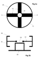
- Figures 1 a and 1b schematically illustrate an example of rotor structure 10 which has been mounted on a supporting structure 14 such as e.g. a pedestal.
- Figure 1a shows the rotor structure 10 which in this example has a rotor rim 11, spokes 12 and a central opening 13 for its coupling with a rotor shaft or with one or more bearings (not shown) depending on the configuration chosen.
- Figure 1b is a schematic representation of a cross sectional view of the rotor structure 10 mounted on the pedestal 14 according to a plane AA indicated in Figure 1a .
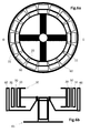
- FIG. 2a is a schematic illustration of a top view of the rotor structure 10 with permanent magnet elements 20.
- Figure 2b schematically shows a cross sectional view of the rotor structure 10 with permanent magnet elements 20 according to a reference plane BB indicated in Figure 2a .
- a permanent magnet element 20 may be a single permanent magnet which is attached directly to the rotor rim 11 through e.g. screws, and/or adhesives, etc.
- a permanent magnet element 20 may be a permanent magnet module which comprises a module base and a plurality of permanent magnets coupled to the module base, such that said permanent magnets are attached together to the rotor rim 11 through the module base.
- a plurality of winding elements 31 can be attached to the permanent magnet elements 20 with a first non-magnetic separator 30 sandwiched between the winding elements 31 and the permanent magnet elements 20.
- a plurality of non-magnetic segments can be suitably arranged (or coupled) in such a way that the first non-magnetic separator 30 is obtained in the form depicted in Figure 3a .
- Advantage can be taken of a magnetic attraction due to a magnetic field created by the permanent magnet elements 20 for implementing this attachment, such that no extra elements (such as e.g. screws, bolts, adhesives, etc.) are required for this aim.
- Figure 3a schematically shows a top view of the arrangement of the rotor structure 10 with permanent magnet elements 20, first non-magnetic separator(s) 30 and winding elements 31.
- Figure 3b is a schematic illustration of a cross sectional view of this arrangement according to a reference plane CC indicated in Figure 3a .
- a region 32 comprising part of the permanent magnet element(s) 20, first non-magnetic separator(s) 30 and winding element(s) 31 is also indicated in Figure 3a , which will be described in detail in other parts of the description.
- a winding element may be a single tooth and coil or, alternatively, a coil module which comprises several teeth and a plurality of coils coupled to these teeth.
- stator bars forming a part of a so-called distributed winding might be used instead of coils.
- the thickness of the first non-magnetic separators 30 may be defined beforehand based on several design factors. The value of this thickness may depend on a specified air-gap 80 (see Figure 8b ) between the rotor and the stator active parts once the assembly of the machine is terminated. Furthermore, this thickness may depend on the manufacturing tolerances, or on a minimum thickness required to avoid demagnetization of the permanent magnet elements 20.
- the first non-magnetic separator(s) 30 may generally have a thickness in a range of approximately 3 mm to 5 mm, and preferably substantially equal to 4 mm.
- all the winding elements 31 and corresponding first separators 30 may be attached to permanent magnet elements 20 as described before, i.e. once permanent magnet elements 20 have been attached to rotor rim 11.
- winding elements 31 and corresponding first separators 30 may be attached to permanent magnet elements 20 once permanent magnet elements 20 have been attached to the rotor rim 11. In this case, remaining winding elements 31 and first separators 30 may be attached to other permanent magnet elements 20 before their attachment to the rotor rim 11.
- FIG 4a schematically shows that second non-magnetic separators 40 may be arranged between winding elements 31 in order to ensure that a desired distance between winding elements 31 is kept.
- the attraction force due to the magnetic field generated by the permanent magnet elements 20 can force the winding elements 31 to be displaced.
- the proposed second non-magnetic separators 40 may have the function of counteracting said forced displacement in such a way that the winding elements 31 remain at an expected position. This may further facilitate the assembling of the electrical machine.
- Permanent magnet elements 20 and winding elements 31 may be separated by first and second non-magnetic separators 30, 40 integrally formed as a single piece similar to the one shown in Figure 4b .
- This single piece may be called herein "complete separator" in the sense that all the permanent magnet elements 20 and winding elements 31 are separated by said single complete separator.
- a plurality of smaller separators having e.g. a first non-magnetic separator 30 and two second non-magnetic separators 40 could be used for obtaining a complete separator.
- These smaller separators may be called herein "local" separators in the sense that they have the function of locally separating particular permanent magnet element(s) 20 and winding element(s) 31.
- Figure 4c schematically illustrates a local separator comprising a first separator 30 (for separating a permanent magnet element 20 and a winding element 31), and two second separators 40 (for separating neighbouring winding elements 31), said first and second separators 30, 40 being integrally formed as a single piece.
- Figure 4d schematically illustrates an alternative local separator comprising a first separator 30 and two second separators 40 which are separate pieces.
- a local separator similar to the one shown in Figure 4c can be obtained by suitably coupling first and second separators 30, 40 and/or suitably placing them between corresponding permanent magnet elements 20 and winding elements 31.
- first non-magnetic separators 30 and second non-magnetic separators 40 may be made of non-magnetic materials such as e.g. plastic, or aluminium, etc.
- a complete separator similar to the one shown in Figure 4b can be obtained by using a suitable number of local separators similar to the ones shown in Figures 4c and/or 4d.
- a first non-magnetic separator 30 between permanent magnet element(s) 20 and winding element(s) 31 may have a form such that a guided interface between the first separator 30 and permanent magnet element(s) 20 and/or winding element(s) 31 can be obtained.
- Figures 5a and 5b show an example of this feature.
- Figures 5a and 5b show a region 32 of an arrangement similar to the one depicted in Figure 3a in which the first separator 30 has protrusions or male parts 56 mating with depressions or female parts 55 of the winding element(s) 31, and protrusions or male parts 58 mating with depressions or female parts 57 of the permanent magnet element(s) 20.
- winding elements (or winding modules) 31 are shown in Figures 5a and 5b having a tooth 50 and corresponding coils or windings 51 coupled to the tooth 50, and the permanent magnet elements (or permanent magnet modules) 20 are shown having a module base 52 and permanent magnets 53, 54 attached to the base 52.
- the permanent magnet modules 20 are shown having an inverted V structure of permanent magnets 53, 54, and the depressions or female parts 57 are shown located substantially at the vertex of the inverted V of magnets 53, 54.
- the coils modules 31 are shown in Figures 5a and 5b having the depressions or female parts 55 at the level of the coils 51.
- Figures 5a and 5b may also be seen as the (coils and/or permanent magnet) modules 20, 31 having protrusions (or male parts) and the first separator 30 having depressions (or female parts) mating with said protrusions (or male parts) of the modules 20, 31.
- the coupling of the permanent magnet modules 20, first separator 30 and winding modules 31 can be performed in a guided manner, such that the modules 20, 31 are correctly positioned with respect to each other's.
- any of the first non-magnetic separators 30 shown in previous figures with the function of separating permanent magnet modules 20 and winding modules 31 may be of the type shown in Figures 5a and 5b , i.e. providing a guided interface.
- Figure 6a schematically illustrates a top view of an arrangement resulting from this assembling
- Figure 6b is a schematic illustration of a cross sectional view of the arrangement of Figure 6a according to a reference plane DD.
- This assembling of the whole rotor structure 10, 20, 30, 31 with the stator structure 60 may be performed by mounting the stator structure 10 on a supporting structure (e.g. a pedestal) 61, and carrying/moving the overall rotor structure 10, 20, 30, 31 for its assembling with (or insertion into) the stator structure 60 by using e.g. suitable crane(s), guiding element(s), etc.
- a supporting structure e.g. a pedestal
- Figure 7a schematically illustrates a top view of this resulting arrangement
- Figure 7b depicts a schematic cross sectional view of said arrangement of Figure 7a according to a reference plane EE.
- Figures 7a and 7b show the winding elements 31 attached or fastened to the stator structure 60 in such a way that release of the non-magnetic separator 30 is caused.
- the fastening of the winding elements 31 to the stator structure 60 may be implemented by using e.g. screws or similar.
- a winding element 31 may be a single tooth and coil (or winding) which is fastened directly to the stator structure 60.
- a winding element 31 may be a coils module having several teeth and a plurality of coils attached to the teeth, such that said coils are attached together to the stator structure 60 through the teeth.
- stator bars forming a part of a so-called distributed winding might be used instead of coils.
- the winding elements 31 as well as the rim of the stator structure 60 may comprise corresponding orifices or any other mechanism allowing the correct positioning of the winding elements 31.
- the orifices allow the fastening of the winding elements 31 to the stator structure 60 by using bolts, screws or any other feasible mechanism.
- Figure 8a is a schematic top view of this resulting arrangement
- Figure 8b schematically shows a cross sectional view of the arrangement of Figure 8a according to a plane of reference FF.
- FIGS. 8a and 8b illustrate that an air gap 80 can result between the permanent magnet elements 20 and the winding elements 31.
- a desired width for the air gap 80 may be obtained with the above methods by using different components suitably sized, such as e.g. the rotor structure 10, the permanent magnets 20 and winding elements 31, the stator structure 60, etc.
- the overall structure of the assembled generator may be dismounted from the supporting structure 61 for e.g. its installation in a wind turbine or other types of apparatus requiring such a machine.
- An aspect of the methods of constructing an electrical machine described with respect to Figures 1a - 8b may be that advantage is taken of a phenomenon which normally represents a problem in prior art methods.
- the magnetic field created by permanent magnet elements 20 may cause, in prior art methods, difficulties in the assembly of the rotor and stator.
- advantage is taken of the magnetic field for implementing the attachment of winding elements 31 and first non-magnetic separators 30 to the permanent magnets 20.
- the permanent magnets are to be comprised in the rotor structure.
- a similar methodology may be applicable for the case where the permanent magnets are to be comprised in the stator structure. In such a case, the operations performed on the rotor structure as defined above will actually need to be performed on the stator structure, and vice-versa.
- the permanent magnets are attached first to the rotor structure (or to the stator structure as briefly indicated above) and the windings are later attached to the magnets with corresponding separator(s) in between.
- a similar methodology may be applicable in which the windings are attached first to the rotor (or stator) structure and the magnets are later attached to the windings with corresponding separator(s) in between.
- the magnets need to be finally attached to the other structure (rotor or stator structure) in order to cause the release of the separator(s).
- stator is described surrounding the rotor and a generator is cited as the output of the assembling methods.
- rotor can surround the stator and/or the output of the assembling methods may be an electrical motor instead of a generator.
Landscapes
- Engineering & Computer Science (AREA)
- Power Engineering (AREA)
- Manufacturing & Machinery (AREA)
- Permanent Field Magnets Of Synchronous Machinery (AREA)
- Manufacture Of Motors, Generators (AREA)
- Permanent Magnet Type Synchronous Machine (AREA)
Priority Applications (2)
| Application Number | Priority Date | Filing Date | Title |
|---|---|---|---|
| EP14382570.1A EP3038239B1 (fr) | 2014-12-24 | 2014-12-24 | Procédés d'assemblage d'une machine électrique |
| US14/971,741 US10498204B2 (en) | 2014-12-24 | 2015-12-16 | Methods of assembling an electrical machine |
Applications Claiming Priority (1)
| Application Number | Priority Date | Filing Date | Title |
|---|---|---|---|
| EP14382570.1A EP3038239B1 (fr) | 2014-12-24 | 2014-12-24 | Procédés d'assemblage d'une machine électrique |
Publications (2)
| Publication Number | Publication Date |
|---|---|
| EP3038239A1 true EP3038239A1 (fr) | 2016-06-29 |
| EP3038239B1 EP3038239B1 (fr) | 2020-03-11 |
Family
ID=52338953
Family Applications (1)
| Application Number | Title | Priority Date | Filing Date |
|---|---|---|---|
| EP14382570.1A Active EP3038239B1 (fr) | 2014-12-24 | 2014-12-24 | Procédés d'assemblage d'une machine électrique |
Country Status (2)
| Country | Link |
|---|---|
| US (1) | US10498204B2 (fr) |
| EP (1) | EP3038239B1 (fr) |
Cited By (1)
| Publication number | Priority date | Publication date | Assignee | Title |
|---|---|---|---|---|
| WO2020238266A1 (fr) * | 2019-05-27 | 2020-12-03 | 北京金风科创风电设备有限公司 | Cadre de support de stator et stator |
Families Citing this family (1)
| Publication number | Priority date | Publication date | Assignee | Title |
|---|---|---|---|---|
| CN106787511A (zh) * | 2016-12-25 | 2017-05-31 | 中船重工电机科技股份有限公司 | 大型同步电动机表贴式磁钢转子入壳工装及入壳方法 |
Citations (4)
| Publication number | Priority date | Publication date | Assignee | Title |
|---|---|---|---|---|
| DE102005042543A1 (de) * | 2005-09-07 | 2007-03-15 | Siemens Ag | Permanenterregte Synchronmaschine |
| EP2381561A2 (fr) * | 2004-09-20 | 2011-10-26 | Wilic S.Ar.L | Eolienne dotée d'un générateur |
| EP2508749A1 (fr) * | 2011-04-04 | 2012-10-10 | Siemens Aktiengesellschaft | Procédé destiné au montage d'une machine électrique |
| EP2536007A1 (fr) * | 2011-06-14 | 2012-12-19 | Siemens Aktiengesellschaft | Procédé pour échanger des segments dans une machine électrique |
Family Cites Families (10)
| Publication number | Priority date | Publication date | Assignee | Title |
|---|---|---|---|---|
| DE1912535B1 (de) * | 1969-03-12 | 1970-10-01 | Ackermann & Schmitt Kg | Kontaktvorrichtung |
| US6487769B2 (en) * | 2000-11-30 | 2002-12-03 | Emerson Electric Co. | Method and apparatus for constructing a segmented stator |
| JP2006304556A (ja) * | 2005-04-22 | 2006-11-02 | Nissan Motor Co Ltd | 回転子磁石の着磁方法 |
| JP2007028725A (ja) * | 2005-07-13 | 2007-02-01 | Matsushita Electric Ind Co Ltd | 異方性ボンド磁石組立体及びその製造方法並びにこの磁石組立体を用いた永久磁石モータ |
| CN101657635B (zh) * | 2007-03-23 | 2012-11-21 | 维斯塔斯风力系统有限公司 | 用一个或一个以上的永磁体(pm)转子建立风力涡轮发电机的方法、风力涡轮机机舱以及风力涡轮机 |
| US8476794B2 (en) * | 2009-05-27 | 2013-07-02 | Empire Technology Development Llc | Wheel motor with rotating outer rotor |
| DE102009032885A1 (de) * | 2009-07-13 | 2011-02-03 | Siemens Aktiengesellschaft | Ringförmiger Rotor für eine elektrische Maschine |
| JP5265615B2 (ja) * | 2010-05-13 | 2013-08-14 | 正志 西村 | 永久磁石埋め込み回転子 |
| DE102011101730A1 (de) * | 2010-06-04 | 2011-12-08 | Ebm-Papst St. Georgen Gmbh & Co. Kg | Elektromotor |
| US20120091719A1 (en) * | 2010-10-18 | 2012-04-19 | Sivaraman Guruswamy | Method and device for energy generation |
-
2014
- 2014-12-24 EP EP14382570.1A patent/EP3038239B1/fr active Active
-
2015
- 2015-12-16 US US14/971,741 patent/US10498204B2/en active Active
Patent Citations (4)
| Publication number | Priority date | Publication date | Assignee | Title |
|---|---|---|---|---|
| EP2381561A2 (fr) * | 2004-09-20 | 2011-10-26 | Wilic S.Ar.L | Eolienne dotée d'un générateur |
| DE102005042543A1 (de) * | 2005-09-07 | 2007-03-15 | Siemens Ag | Permanenterregte Synchronmaschine |
| EP2508749A1 (fr) * | 2011-04-04 | 2012-10-10 | Siemens Aktiengesellschaft | Procédé destiné au montage d'une machine électrique |
| EP2536007A1 (fr) * | 2011-06-14 | 2012-12-19 | Siemens Aktiengesellschaft | Procédé pour échanger des segments dans une machine électrique |
Cited By (2)
| Publication number | Priority date | Publication date | Assignee | Title |
|---|---|---|---|---|
| WO2020238266A1 (fr) * | 2019-05-27 | 2020-12-03 | 北京金风科创风电设备有限公司 | Cadre de support de stator et stator |
| US12381426B2 (en) | 2019-05-27 | 2025-08-05 | Beijing Goldwind Science & Creation Windpower Equipment Co., Ltd. | Stator support for large-diameter electric motor and stator |
Also Published As
| Publication number | Publication date |
|---|---|
| EP3038239B1 (fr) | 2020-03-11 |
| US10498204B2 (en) | 2019-12-03 |
| US20160190901A1 (en) | 2016-06-30 |
Similar Documents
| Publication | Publication Date | Title |
|---|---|---|
| EP2731232B1 (fr) | Générateur pour éolienne | |
| JP5591331B2 (ja) | 発電機および発電機の製造方法 | |
| EP2467922B1 (fr) | Appareil et procédé pour installer des aimants permanents dans une machine électromécanique | |
| CN108432089B (zh) | 具有由模块组成的定子环的用于轴向磁通机械的定子 | |
| EP2645537B1 (fr) | Rotor à aimant permanent | |
| CN102957232B (zh) | 定子 | |
| US20080185932A1 (en) | Tooth Module for a Primary Part, with Permanent-Magnet Excitation, of an Electrical Machine | |
| US20120187793A1 (en) | Rotor | |
| US12289016B2 (en) | Rotating electric machine and stator manufacturing method | |
| EP2727219A2 (fr) | Machine pm économique à faible saillance | |
| CN105186743A (zh) | 一种永磁电机的转子机构 | |
| EP2645535A1 (fr) | Rotor à aimant permanent | |
| EP3001542B1 (fr) | Rotors à aimant permanent | |
| EP2645536B1 (fr) | Rotor à aimant permanent | |
| CN102971942A (zh) | 风力涡轮发电机用的磁体盖板组件及其布置、安装和拆卸方法 | |
| US10498204B2 (en) | Methods of assembling an electrical machine | |
| CN101877503A (zh) | 叠片式定子组件 | |
| US20130285499A1 (en) | Rotor magnet engagement assembly | |
| CN111164867B (zh) | 用于电机的径向多件式转子 | |
| EP3001539B1 (fr) | Machines électriques | |
| US20140062238A1 (en) | Modular electrical machine | |
| JP4771011B1 (ja) | 回転電機および風力発電システム | |
| CN223652023U (zh) | 一种轴向磁通电机 | |
| KR20130077140A (ko) | 자석이탈 방지장치를 구비한 자속집중형 모터의 로터 구조 | |
| EP3402046B1 (fr) | Modules à aimants permanents |
Legal Events
| Date | Code | Title | Description |
|---|---|---|---|
| PUAI | Public reference made under article 153(3) epc to a published international application that has entered the european phase |
Free format text: ORIGINAL CODE: 0009012 |
|
| AK | Designated contracting states |
Kind code of ref document: A1 Designated state(s): AL AT BE BG CH CY CZ DE DK EE ES FI FR GB GR HR HU IE IS IT LI LT LU LV MC MK MT NL NO PL PT RO RS SE SI SK SM TR |
|
| AX | Request for extension of the european patent |
Extension state: BA ME |
|
| STAA | Information on the status of an ep patent application or granted ep patent |
Free format text: STATUS: REQUEST FOR EXAMINATION WAS MADE |
|
| 17P | Request for examination filed |
Effective date: 20170102 |
|
| RBV | Designated contracting states (corrected) |
Designated state(s): AL AT BE BG CH CY CZ DE DK EE ES FI FR GB GR HR HU IE IS IT LI LT LU LV MC MK MT NL NO PL PT RO RS SE SI SK SM TR |
|
| RAP1 | Party data changed (applicant data changed or rights of an application transferred) |
Owner name: GE RENEWABLE TECHNOLOGIES WIND B.V. |
|
| STAA | Information on the status of an ep patent application or granted ep patent |
Free format text: STATUS: EXAMINATION IS IN PROGRESS |
|
| 17Q | First examination report despatched |
Effective date: 20190102 |
|
| GRAP | Despatch of communication of intention to grant a patent |
Free format text: ORIGINAL CODE: EPIDOSNIGR1 |
|
| STAA | Information on the status of an ep patent application or granted ep patent |
Free format text: STATUS: GRANT OF PATENT IS INTENDED |
|
| INTG | Intention to grant announced |
Effective date: 20191007 |
|
| GRAS | Grant fee paid |
Free format text: ORIGINAL CODE: EPIDOSNIGR3 |
|
| GRAA | (expected) grant |
Free format text: ORIGINAL CODE: 0009210 |
|
| STAA | Information on the status of an ep patent application or granted ep patent |
Free format text: STATUS: THE PATENT HAS BEEN GRANTED |
|
| AK | Designated contracting states |
Kind code of ref document: B1 Designated state(s): AL AT BE BG CH CY CZ DE DK EE ES FI FR GB GR HR HU IE IS IT LI LT LU LV MC MK MT NL NO PL PT RO RS SE SI SK SM TR |
|
| REG | Reference to a national code |
Ref country code: GB Ref legal event code: FG4D |
|
| REG | Reference to a national code |
Ref country code: CH Ref legal event code: EP |
|
| REG | Reference to a national code |
Ref country code: AT Ref legal event code: REF Ref document number: 1244393 Country of ref document: AT Kind code of ref document: T Effective date: 20200315 |
|
| REG | Reference to a national code |
Ref country code: IE Ref legal event code: FG4D |
|
| REG | Reference to a national code |
Ref country code: DE Ref legal event code: R096 Ref document number: 602014062120 Country of ref document: DE |
|
| REG | Reference to a national code |
Ref country code: NL Ref legal event code: FP |
|
| PG25 | Lapsed in a contracting state [announced via postgrant information from national office to epo] |
Ref country code: RS Free format text: LAPSE BECAUSE OF FAILURE TO SUBMIT A TRANSLATION OF THE DESCRIPTION OR TO PAY THE FEE WITHIN THE PRESCRIBED TIME-LIMIT Effective date: 20200311 Ref country code: FI Free format text: LAPSE BECAUSE OF FAILURE TO SUBMIT A TRANSLATION OF THE DESCRIPTION OR TO PAY THE FEE WITHIN THE PRESCRIBED TIME-LIMIT Effective date: 20200311 Ref country code: NO Free format text: LAPSE BECAUSE OF FAILURE TO SUBMIT A TRANSLATION OF THE DESCRIPTION OR TO PAY THE FEE WITHIN THE PRESCRIBED TIME-LIMIT Effective date: 20200611 |
|
| PG25 | Lapsed in a contracting state [announced via postgrant information from national office to epo] |
Ref country code: SE Free format text: LAPSE BECAUSE OF FAILURE TO SUBMIT A TRANSLATION OF THE DESCRIPTION OR TO PAY THE FEE WITHIN THE PRESCRIBED TIME-LIMIT Effective date: 20200311 Ref country code: LV Free format text: LAPSE BECAUSE OF FAILURE TO SUBMIT A TRANSLATION OF THE DESCRIPTION OR TO PAY THE FEE WITHIN THE PRESCRIBED TIME-LIMIT Effective date: 20200311 Ref country code: BG Free format text: LAPSE BECAUSE OF FAILURE TO SUBMIT A TRANSLATION OF THE DESCRIPTION OR TO PAY THE FEE WITHIN THE PRESCRIBED TIME-LIMIT Effective date: 20200611 Ref country code: HR Free format text: LAPSE BECAUSE OF FAILURE TO SUBMIT A TRANSLATION OF THE DESCRIPTION OR TO PAY THE FEE WITHIN THE PRESCRIBED TIME-LIMIT Effective date: 20200311 Ref country code: GR Free format text: LAPSE BECAUSE OF FAILURE TO SUBMIT A TRANSLATION OF THE DESCRIPTION OR TO PAY THE FEE WITHIN THE PRESCRIBED TIME-LIMIT Effective date: 20200612 |
|
| REG | Reference to a national code |
Ref country code: LT Ref legal event code: MG4D |
|
| PG25 | Lapsed in a contracting state [announced via postgrant information from national office to epo] |
Ref country code: EE Free format text: LAPSE BECAUSE OF FAILURE TO SUBMIT A TRANSLATION OF THE DESCRIPTION OR TO PAY THE FEE WITHIN THE PRESCRIBED TIME-LIMIT Effective date: 20200311 Ref country code: LT Free format text: LAPSE BECAUSE OF FAILURE TO SUBMIT A TRANSLATION OF THE DESCRIPTION OR TO PAY THE FEE WITHIN THE PRESCRIBED TIME-LIMIT Effective date: 20200311 Ref country code: SM Free format text: LAPSE BECAUSE OF FAILURE TO SUBMIT A TRANSLATION OF THE DESCRIPTION OR TO PAY THE FEE WITHIN THE PRESCRIBED TIME-LIMIT Effective date: 20200311 Ref country code: RO Free format text: LAPSE BECAUSE OF FAILURE TO SUBMIT A TRANSLATION OF THE DESCRIPTION OR TO PAY THE FEE WITHIN THE PRESCRIBED TIME-LIMIT Effective date: 20200311 Ref country code: CZ Free format text: LAPSE BECAUSE OF FAILURE TO SUBMIT A TRANSLATION OF THE DESCRIPTION OR TO PAY THE FEE WITHIN THE PRESCRIBED TIME-LIMIT Effective date: 20200311 Ref country code: IS Free format text: LAPSE BECAUSE OF FAILURE TO SUBMIT A TRANSLATION OF THE DESCRIPTION OR TO PAY THE FEE WITHIN THE PRESCRIBED TIME-LIMIT Effective date: 20200711 Ref country code: PT Free format text: LAPSE BECAUSE OF FAILURE TO SUBMIT A TRANSLATION OF THE DESCRIPTION OR TO PAY THE FEE WITHIN THE PRESCRIBED TIME-LIMIT Effective date: 20200805 Ref country code: SK Free format text: LAPSE BECAUSE OF FAILURE TO SUBMIT A TRANSLATION OF THE DESCRIPTION OR TO PAY THE FEE WITHIN THE PRESCRIBED TIME-LIMIT Effective date: 20200311 |
|
| REG | Reference to a national code |
Ref country code: AT Ref legal event code: MK05 Ref document number: 1244393 Country of ref document: AT Kind code of ref document: T Effective date: 20200311 |
|
| REG | Reference to a national code |
Ref country code: DE Ref legal event code: R097 Ref document number: 602014062120 Country of ref document: DE |
|
| PLBE | No opposition filed within time limit |
Free format text: ORIGINAL CODE: 0009261 |
|
| STAA | Information on the status of an ep patent application or granted ep patent |
Free format text: STATUS: NO OPPOSITION FILED WITHIN TIME LIMIT |
|
| PG25 | Lapsed in a contracting state [announced via postgrant information from national office to epo] |
Ref country code: ES Free format text: LAPSE BECAUSE OF FAILURE TO SUBMIT A TRANSLATION OF THE DESCRIPTION OR TO PAY THE FEE WITHIN THE PRESCRIBED TIME-LIMIT Effective date: 20200311 Ref country code: IT Free format text: LAPSE BECAUSE OF FAILURE TO SUBMIT A TRANSLATION OF THE DESCRIPTION OR TO PAY THE FEE WITHIN THE PRESCRIBED TIME-LIMIT Effective date: 20200311 Ref country code: AT Free format text: LAPSE BECAUSE OF FAILURE TO SUBMIT A TRANSLATION OF THE DESCRIPTION OR TO PAY THE FEE WITHIN THE PRESCRIBED TIME-LIMIT Effective date: 20200311 Ref country code: DK Free format text: LAPSE BECAUSE OF FAILURE TO SUBMIT A TRANSLATION OF THE DESCRIPTION OR TO PAY THE FEE WITHIN THE PRESCRIBED TIME-LIMIT Effective date: 20200311 |
|
| 26N | No opposition filed |
Effective date: 20201214 |
|
| PG25 | Lapsed in a contracting state [announced via postgrant information from national office to epo] |
Ref country code: SI Free format text: LAPSE BECAUSE OF FAILURE TO SUBMIT A TRANSLATION OF THE DESCRIPTION OR TO PAY THE FEE WITHIN THE PRESCRIBED TIME-LIMIT Effective date: 20200311 Ref country code: PL Free format text: LAPSE BECAUSE OF FAILURE TO SUBMIT A TRANSLATION OF THE DESCRIPTION OR TO PAY THE FEE WITHIN THE PRESCRIBED TIME-LIMIT Effective date: 20200311 |
|
| REG | Reference to a national code |
Ref country code: CH Ref legal event code: PL |
|
| PG25 | Lapsed in a contracting state [announced via postgrant information from national office to epo] |
Ref country code: MC Free format text: LAPSE BECAUSE OF FAILURE TO SUBMIT A TRANSLATION OF THE DESCRIPTION OR TO PAY THE FEE WITHIN THE PRESCRIBED TIME-LIMIT Effective date: 20200311 |
|
| REG | Reference to a national code |
Ref country code: BE Ref legal event code: MM Effective date: 20201231 |
|
| PG25 | Lapsed in a contracting state [announced via postgrant information from national office to epo] |
Ref country code: FR Free format text: LAPSE BECAUSE OF NON-PAYMENT OF DUE FEES Effective date: 20201231 Ref country code: LU Free format text: LAPSE BECAUSE OF NON-PAYMENT OF DUE FEES Effective date: 20201224 Ref country code: IE Free format text: LAPSE BECAUSE OF NON-PAYMENT OF DUE FEES Effective date: 20201224 |
|
| PG25 | Lapsed in a contracting state [announced via postgrant information from national office to epo] |
Ref country code: LI Free format text: LAPSE BECAUSE OF NON-PAYMENT OF DUE FEES Effective date: 20201231 Ref country code: CH Free format text: LAPSE BECAUSE OF NON-PAYMENT OF DUE FEES Effective date: 20201231 |
|
| PG25 | Lapsed in a contracting state [announced via postgrant information from national office to epo] |
Ref country code: TR Free format text: LAPSE BECAUSE OF FAILURE TO SUBMIT A TRANSLATION OF THE DESCRIPTION OR TO PAY THE FEE WITHIN THE PRESCRIBED TIME-LIMIT Effective date: 20200311 Ref country code: MT Free format text: LAPSE BECAUSE OF FAILURE TO SUBMIT A TRANSLATION OF THE DESCRIPTION OR TO PAY THE FEE WITHIN THE PRESCRIBED TIME-LIMIT Effective date: 20200311 Ref country code: CY Free format text: LAPSE BECAUSE OF FAILURE TO SUBMIT A TRANSLATION OF THE DESCRIPTION OR TO PAY THE FEE WITHIN THE PRESCRIBED TIME-LIMIT Effective date: 20200311 |
|
| PG25 | Lapsed in a contracting state [announced via postgrant information from national office to epo] |
Ref country code: MK Free format text: LAPSE BECAUSE OF FAILURE TO SUBMIT A TRANSLATION OF THE DESCRIPTION OR TO PAY THE FEE WITHIN THE PRESCRIBED TIME-LIMIT Effective date: 20200311 Ref country code: AL Free format text: LAPSE BECAUSE OF FAILURE TO SUBMIT A TRANSLATION OF THE DESCRIPTION OR TO PAY THE FEE WITHIN THE PRESCRIBED TIME-LIMIT Effective date: 20200311 |
|
| PG25 | Lapsed in a contracting state [announced via postgrant information from national office to epo] |
Ref country code: BE Free format text: LAPSE BECAUSE OF NON-PAYMENT OF DUE FEES Effective date: 20201231 |
|
| P01 | Opt-out of the competence of the unified patent court (upc) registered |
Effective date: 20230529 |
|
| PGFP | Annual fee paid to national office [announced via postgrant information from national office to epo] |
Ref country code: NL Payment date: 20251119 Year of fee payment: 12 |
|
| PGFP | Annual fee paid to national office [announced via postgrant information from national office to epo] |
Ref country code: DE Payment date: 20251126 Year of fee payment: 12 |
|
| PGFP | Annual fee paid to national office [announced via postgrant information from national office to epo] |
Ref country code: GB Payment date: 20251119 Year of fee payment: 12 |