EP3038246B1 - Topologie de circuit à conversion continu-alternatif - Google Patents
Topologie de circuit à conversion continu-alternatif Download PDFInfo
- Publication number
- EP3038246B1 EP3038246B1 EP16153005.0A EP16153005A EP3038246B1 EP 3038246 B1 EP3038246 B1 EP 3038246B1 EP 16153005 A EP16153005 A EP 16153005A EP 3038246 B1 EP3038246 B1 EP 3038246B1
- Authority
- EP
- European Patent Office
- Prior art keywords
- voltage converter
- voltage
- inductor
- terminal
- input
- Prior art date
- Legal status (The legal status is an assumption and is not a legal conclusion. Google has not performed a legal analysis and makes no representation as to the accuracy of the status listed.)
- Active
Links
Images




Classifications
-
- H—ELECTRICITY
- H02—GENERATION; CONVERSION OR DISTRIBUTION OF ELECTRIC POWER
- H02M—APPARATUS FOR CONVERSION BETWEEN AC AND AC, BETWEEN AC AND DC, OR BETWEEN DC AND DC, AND FOR USE WITH MAINS OR SIMILAR POWER SUPPLY SYSTEMS; CONVERSION OF DC OR AC INPUT POWER INTO SURGE OUTPUT POWER; CONTROL OR REGULATION THEREOF
- H02M7/00—Conversion of AC power input into DC power output; Conversion of DC power input into AC power output
- H02M7/66—Conversion of AC power input into DC power output; Conversion of DC power input into AC power output with possibility of reversal
- H02M7/68—Conversion of AC power input into DC power output; Conversion of DC power input into AC power output with possibility of reversal by static converters
- H02M7/72—Conversion of AC power input into DC power output; Conversion of DC power input into AC power output with possibility of reversal by static converters using discharge tubes with control electrode or semiconductor devices with control electrode
-
- H—ELECTRICITY
- H02—GENERATION; CONVERSION OR DISTRIBUTION OF ELECTRIC POWER
- H02M—APPARATUS FOR CONVERSION BETWEEN AC AND AC, BETWEEN AC AND DC, OR BETWEEN DC AND DC, AND FOR USE WITH MAINS OR SIMILAR POWER SUPPLY SYSTEMS; CONVERSION OF DC OR AC INPUT POWER INTO SURGE OUTPUT POWER; CONTROL OR REGULATION THEREOF
- H02M1/00—Details of apparatus for conversion
- H02M1/44—Circuits or arrangements for compensating for electromagnetic interference in converters or inverters
-
- H—ELECTRICITY
- H02—GENERATION; CONVERSION OR DISTRIBUTION OF ELECTRIC POWER
- H02M—APPARATUS FOR CONVERSION BETWEEN AC AND AC, BETWEEN AC AND DC, OR BETWEEN DC AND DC, AND FOR USE WITH MAINS OR SIMILAR POWER SUPPLY SYSTEMS; CONVERSION OF DC OR AC INPUT POWER INTO SURGE OUTPUT POWER; CONTROL OR REGULATION THEREOF
- H02M3/00—Conversion of DC power input into DC power output
- H02M3/22—Conversion of DC power input into DC power output with intermediate conversion into AC
- H02M3/24—Conversion of DC power input into DC power output with intermediate conversion into AC by static converters
- H02M3/28—Conversion of DC power input into DC power output with intermediate conversion into AC by static converters using discharge tubes with control electrode or semiconductor devices with control electrode to produce the intermediate AC
-
- H—ELECTRICITY
- H02—GENERATION; CONVERSION OR DISTRIBUTION OF ELECTRIC POWER
- H02M—APPARATUS FOR CONVERSION BETWEEN AC AND AC, BETWEEN AC AND DC, OR BETWEEN DC AND DC, AND FOR USE WITH MAINS OR SIMILAR POWER SUPPLY SYSTEMS; CONVERSION OF DC OR AC INPUT POWER INTO SURGE OUTPUT POWER; CONTROL OR REGULATION THEREOF
- H02M5/00—Conversion of AC power input into AC power output, e.g. for change of voltage, for change of frequency, for change of number of phases
- H02M5/40—Conversion of AC power input into AC power output, e.g. for change of voltage, for change of frequency, for change of number of phases with intermediate conversion into DC
- H02M5/42—Conversion of AC power input into AC power output, e.g. for change of voltage, for change of frequency, for change of number of phases with intermediate conversion into DC by static converters
- H02M5/44—Conversion of AC power input into AC power output, e.g. for change of voltage, for change of frequency, for change of number of phases with intermediate conversion into DC by static converters using discharge tubes or semiconductor devices to convert the intermediate DC into AC
- H02M5/453—Conversion of AC power input into AC power output, e.g. for change of voltage, for change of frequency, for change of number of phases with intermediate conversion into DC by static converters using discharge tubes or semiconductor devices to convert the intermediate DC into AC using devices of a triode or transistor type requiring continuous application of a control signal
- H02M5/458—Conversion of AC power input into AC power output, e.g. for change of voltage, for change of frequency, for change of number of phases with intermediate conversion into DC by static converters using discharge tubes or semiconductor devices to convert the intermediate DC into AC using devices of a triode or transistor type requiring continuous application of a control signal using semiconductor devices only
-
- H—ELECTRICITY
- H02—GENERATION; CONVERSION OR DISTRIBUTION OF ELECTRIC POWER
- H02M—APPARATUS FOR CONVERSION BETWEEN AC AND AC, BETWEEN AC AND DC, OR BETWEEN DC AND DC, AND FOR USE WITH MAINS OR SIMILAR POWER SUPPLY SYSTEMS; CONVERSION OF DC OR AC INPUT POWER INTO SURGE OUTPUT POWER; CONTROL OR REGULATION THEREOF
- H02M7/00—Conversion of AC power input into DC power output; Conversion of DC power input into AC power output
- H02M7/02—Conversion of AC power input into DC power output without possibility of reversal
- H02M7/04—Conversion of AC power input into DC power output without possibility of reversal by static converters
- H02M7/06—Conversion of AC power input into DC power output without possibility of reversal by static converters using discharge tubes without control electrode or semiconductor devices without control electrode
-
- H—ELECTRICITY
- H02—GENERATION; CONVERSION OR DISTRIBUTION OF ELECTRIC POWER
- H02M—APPARATUS FOR CONVERSION BETWEEN AC AND AC, BETWEEN AC AND DC, OR BETWEEN DC AND DC, AND FOR USE WITH MAINS OR SIMILAR POWER SUPPLY SYSTEMS; CONVERSION OF DC OR AC INPUT POWER INTO SURGE OUTPUT POWER; CONTROL OR REGULATION THEREOF
- H02M7/00—Conversion of AC power input into DC power output; Conversion of DC power input into AC power output
- H02M7/42—Conversion of DC power input into AC power output without possibility of reversal
- H02M7/44—Conversion of DC power input into AC power output without possibility of reversal by static converters
- H02M7/48—Conversion of DC power input into AC power output without possibility of reversal by static converters using discharge tubes with control electrode or semiconductor devices with control electrode
- H02M7/4807—Conversion of DC power input into AC power output without possibility of reversal by static converters using discharge tubes with control electrode or semiconductor devices with control electrode having a high frequency intermediate AC stage
-
- H—ELECTRICITY
- H02—GENERATION; CONVERSION OR DISTRIBUTION OF ELECTRIC POWER
- H02M—APPARATUS FOR CONVERSION BETWEEN AC AND AC, BETWEEN AC AND DC, OR BETWEEN DC AND DC, AND FOR USE WITH MAINS OR SIMILAR POWER SUPPLY SYSTEMS; CONVERSION OF DC OR AC INPUT POWER INTO SURGE OUTPUT POWER; CONTROL OR REGULATION THEREOF
- H02M7/00—Conversion of AC power input into DC power output; Conversion of DC power input into AC power output
- H02M7/42—Conversion of DC power input into AC power output without possibility of reversal
- H02M7/44—Conversion of DC power input into AC power output without possibility of reversal by static converters
- H02M7/48—Conversion of DC power input into AC power output without possibility of reversal by static converters using discharge tubes with control electrode or semiconductor devices with control electrode
- H02M7/505—Conversion of DC power input into AC power output without possibility of reversal by static converters using discharge tubes with control electrode or semiconductor devices with control electrode using devices of a thyratron or thyristor type requiring extinguishing means
- H02M7/515—Conversion of DC power input into AC power output without possibility of reversal by static converters using discharge tubes with control electrode or semiconductor devices with control electrode using devices of a thyratron or thyristor type requiring extinguishing means using semiconductor devices only
-
- H—ELECTRICITY
- H02—GENERATION; CONVERSION OR DISTRIBUTION OF ELECTRIC POWER
- H02M—APPARATUS FOR CONVERSION BETWEEN AC AND AC, BETWEEN AC AND DC, OR BETWEEN DC AND DC, AND FOR USE WITH MAINS OR SIMILAR POWER SUPPLY SYSTEMS; CONVERSION OF DC OR AC INPUT POWER INTO SURGE OUTPUT POWER; CONTROL OR REGULATION THEREOF
- H02M7/00—Conversion of AC power input into DC power output; Conversion of DC power input into AC power output
- H02M7/42—Conversion of DC power input into AC power output without possibility of reversal
- H02M7/44—Conversion of DC power input into AC power output without possibility of reversal by static converters
- H02M7/48—Conversion of DC power input into AC power output without possibility of reversal by static converters using discharge tubes with control electrode or semiconductor devices with control electrode
- H02M7/53—Conversion of DC power input into AC power output without possibility of reversal by static converters using discharge tubes with control electrode or semiconductor devices with control electrode using devices of a triode or transistor type requiring continuous application of a control signal
- H02M7/537—Conversion of DC power input into AC power output without possibility of reversal by static converters using discharge tubes with control electrode or semiconductor devices with control electrode using devices of a triode or transistor type requiring continuous application of a control signal using semiconductor devices only, e.g. single switched pulse inverters
-
- H—ELECTRICITY
- H02—GENERATION; CONVERSION OR DISTRIBUTION OF ELECTRIC POWER
- H02M—APPARATUS FOR CONVERSION BETWEEN AC AND AC, BETWEEN AC AND DC, OR BETWEEN DC AND DC, AND FOR USE WITH MAINS OR SIMILAR POWER SUPPLY SYSTEMS; CONVERSION OF DC OR AC INPUT POWER INTO SURGE OUTPUT POWER; CONTROL OR REGULATION THEREOF
- H02M7/00—Conversion of AC power input into DC power output; Conversion of DC power input into AC power output
- H02M7/66—Conversion of AC power input into DC power output; Conversion of DC power input into AC power output with possibility of reversal
- H02M7/68—Conversion of AC power input into DC power output; Conversion of DC power input into AC power output with possibility of reversal by static converters
- H02M7/72—Conversion of AC power input into DC power output; Conversion of DC power input into AC power output with possibility of reversal by static converters using discharge tubes with control electrode or semiconductor devices with control electrode
- H02M7/79—Conversion of AC power input into DC power output; Conversion of DC power input into AC power output with possibility of reversal by static converters using discharge tubes with control electrode or semiconductor devices with control electrode using devices of a triode or transistor type requiring continuous application of a control signal
- H02M7/797—Conversion of AC power input into DC power output; Conversion of DC power input into AC power output with possibility of reversal by static converters using discharge tubes with control electrode or semiconductor devices with control electrode using devices of a triode or transistor type requiring continuous application of a control signal using semiconductor devices only
-
- H—ELECTRICITY
- H02—GENERATION; CONVERSION OR DISTRIBUTION OF ELECTRIC POWER
- H02M—APPARATUS FOR CONVERSION BETWEEN AC AND AC, BETWEEN AC AND DC, OR BETWEEN DC AND DC, AND FOR USE WITH MAINS OR SIMILAR POWER SUPPLY SYSTEMS; CONVERSION OF DC OR AC INPUT POWER INTO SURGE OUTPUT POWER; CONTROL OR REGULATION THEREOF
- H02M1/00—Details of apparatus for conversion
- H02M1/0045—Converters combining the concepts of switch-mode regulation and linear regulation, e.g. linear pre-regulator to switching converter, linear and switching converter in parallel, same converter or same transistor operating either in linear or switching mode
-
- H—ELECTRICITY
- H02—GENERATION; CONVERSION OR DISTRIBUTION OF ELECTRIC POWER
- H02M—APPARATUS FOR CONVERSION BETWEEN AC AND AC, BETWEEN AC AND DC, OR BETWEEN DC AND DC, AND FOR USE WITH MAINS OR SIMILAR POWER SUPPLY SYSTEMS; CONVERSION OF DC OR AC INPUT POWER INTO SURGE OUTPUT POWER; CONTROL OR REGULATION THEREOF
- H02M1/00—Details of apparatus for conversion
- H02M1/0048—Circuits or arrangements for reducing losses
- H02M1/0054—Transistor switching losses
- H02M1/0058—Transistor switching losses by employing soft switching techniques, i.e. commutation of transistors when applied voltage is zero or when current flow is zero
-
- H—ELECTRICITY
- H02—GENERATION; CONVERSION OR DISTRIBUTION OF ELECTRIC POWER
- H02M—APPARATUS FOR CONVERSION BETWEEN AC AND AC, BETWEEN AC AND DC, OR BETWEEN DC AND DC, AND FOR USE WITH MAINS OR SIMILAR POWER SUPPLY SYSTEMS; CONVERSION OF DC OR AC INPUT POWER INTO SURGE OUTPUT POWER; CONTROL OR REGULATION THEREOF
- H02M1/00—Details of apparatus for conversion
- H02M1/0067—Converter structures employing plural converter units, other than for parallel operation of the units on a single load
- H02M1/007—Plural converter units in cascade
-
- H—ELECTRICITY
- H02—GENERATION; CONVERSION OR DISTRIBUTION OF ELECTRIC POWER
- H02M—APPARATUS FOR CONVERSION BETWEEN AC AND AC, BETWEEN AC AND DC, OR BETWEEN DC AND DC, AND FOR USE WITH MAINS OR SIMILAR POWER SUPPLY SYSTEMS; CONVERSION OF DC OR AC INPUT POWER INTO SURGE OUTPUT POWER; CONTROL OR REGULATION THEREOF
- H02M1/00—Details of apparatus for conversion
- H02M1/0067—Converter structures employing plural converter units, other than for parallel operation of the units on a single load
- H02M1/0074—Plural converter units whose inputs are connected in series
-
- H—ELECTRICITY
- H02—GENERATION; CONVERSION OR DISTRIBUTION OF ELECTRIC POWER
- H02M—APPARATUS FOR CONVERSION BETWEEN AC AND AC, BETWEEN AC AND DC, OR BETWEEN DC AND DC, AND FOR USE WITH MAINS OR SIMILAR POWER SUPPLY SYSTEMS; CONVERSION OF DC OR AC INPUT POWER INTO SURGE OUTPUT POWER; CONTROL OR REGULATION THEREOF
- H02M3/00—Conversion of DC power input into DC power output
- H02M3/005—Conversion of DC power input into DC power output using Cuk converters
-
- H—ELECTRICITY
- H02—GENERATION; CONVERSION OR DISTRIBUTION OF ELECTRIC POWER
- H02M—APPARATUS FOR CONVERSION BETWEEN AC AND AC, BETWEEN AC AND DC, OR BETWEEN DC AND DC, AND FOR USE WITH MAINS OR SIMILAR POWER SUPPLY SYSTEMS; CONVERSION OF DC OR AC INPUT POWER INTO SURGE OUTPUT POWER; CONTROL OR REGULATION THEREOF
- H02M3/00—Conversion of DC power input into DC power output
- H02M3/02—Conversion of DC power input into DC power output without intermediate conversion into AC
- H02M3/04—Conversion of DC power input into DC power output without intermediate conversion into AC by static converters
- H02M3/10—Conversion of DC power input into DC power output without intermediate conversion into AC by static converters using discharge tubes with control electrode or semiconductor devices with control electrode
- H02M3/145—Conversion of DC power input into DC power output without intermediate conversion into AC by static converters using discharge tubes with control electrode or semiconductor devices with control electrode using devices of a triode or transistor type requiring continuous application of a control signal
- H02M3/155—Conversion of DC power input into DC power output without intermediate conversion into AC by static converters using discharge tubes with control electrode or semiconductor devices with control electrode using devices of a triode or transistor type requiring continuous application of a control signal using semiconductor devices only
- H02M3/1557—Single ended primary inductor converters [SEPIC]
-
- Y—GENERAL TAGGING OF NEW TECHNOLOGICAL DEVELOPMENTS; GENERAL TAGGING OF CROSS-SECTIONAL TECHNOLOGIES SPANNING OVER SEVERAL SECTIONS OF THE IPC; TECHNICAL SUBJECTS COVERED BY FORMER USPC CROSS-REFERENCE ART COLLECTIONS [XRACs] AND DIGESTS
- Y02—TECHNOLOGIES OR APPLICATIONS FOR MITIGATION OR ADAPTATION AGAINST CLIMATE CHANGE
- Y02B—CLIMATE CHANGE MITIGATION TECHNOLOGIES RELATED TO BUILDINGS, e.g. HOUSING, HOUSE APPLIANCES OR RELATED END-USER APPLICATIONS
- Y02B70/00—Technologies for an efficient end-user side electric power management and consumption
- Y02B70/10—Technologies improving the efficiency by using switched-mode power supplies [SMPS], i.e. efficient power electronics conversion e.g. power factor correction or reduction of losses in power supplies or efficient standby modes
Definitions
- the present invention relates generally to voltage converter systems, in particular to systems adapted to convert direct-current (DC) voltages to alternating-current (AC) voltages and vice versa.
- DC direct-current
- AC alternating-current
- a DC-AC voltage converter is an electrical system that changes a DC voltage to an AC voltage.
- the converted AC voltage may have any desired voltage level, waveform and frequency with the use of appropriate transformers, switching, filtering and control circuits.
- DC-AC voltage converters are used in a wide range of applications, from small switching power supplies in electronic devices such as computers to large electric utility high-voltage direct current applications that transport bulk power.
- DC-AC voltage converters are also commonly used to supply AC power from DC sources such as solar panels or batteries.
- Fig. 1 shows a typical prior art DC-AC voltage converter 10, which operates at a relatively low frequency.
- Voltage converter 10 is relatively simple, but it suffers from significant disadvantages.
- a first disadvantage is cost, because it uses a low-frequency transformer 12 that requires a relatively large amount of copper for transformer windings. In recent years the cost of copper has increased, while the cost of power semiconductors has decreased. This trend is expected to continue.
- a low-frequency transformer has relatively low efficiency when it is configured with a relatively high winding turns ratio and is used for voltage step-up.
- An example of such configurations is a DC-AC voltage converter with a step-up transformer having a turns ratio of about 19:1 or more and a relatively low input voltage power source, for example about 10 to 20 volts DC.
- WO 2012/146414A2 depicts a DC/DC converter connected to a DC/AC converter, depicting "Udc" as a series of positive voltage pulses feeding a DC/AC converter which outputs "Uac” depicted as a sinusoidal waveform.
- US 2012/228938 A1 discloses various buck and boost/buck converters driving various bridge circuits.
- Fig. 1 of US 2012/228938 A1 shows a buck converter 11 and a downstream B4 bridge.
- Fig. 2 of US 2012/228938 A1 shows a buck converter 21 and a B4 bridge 22.
- Fig. 3 of US 2012/228938 A1 shows a boost/buck converter 31 and a B4 bridge 32.
- Fig. 4 of US 2012/228938 A1 shows a boost/buck converter 41 and a B4 bridge 42.
- US 2010/118575 A1 discloses a power inverter utilizing a bridge circuit driven by a switch, inductor, and diode connected to a DC source.
- the present invention is a DC-AC voltage converter capable of operating with a relatively low DC voltage source input, such as from a battery power supply.
- the DC-AC voltage converter may be bidirectional, thereby capable of receiving an AC voltage signal and generating an output DC voltage signal. This arrangement is useful, for example, for charging a battery from an AC grid.
- a transformer is utilized to provide electrical isolation for DC-AC and AC-DC conversion.
- an isolation transformer may be used between a DC voltage input (e.g., a battery) and an AC voltage output.
- the voltage converters of the present invention may be generally divided into several types according to the type of transformer selected.
- the isolation transformers may be relatively low-frequency, on the order of 50/60 Hertz (Hz).
- the isolation transformers are relatively high-frequency, on the order of tens or more kilohertz (kHz).
- An aspect out of the scope of the present invention is a voltage converter system that includes a first, high-frequency, DC-AC voltage converter configured to receive a first DC voltage signal and generate a first AC voltage signal.
- a DC link is configured to receive the first AC voltage signal and convert the first AC voltage signal to a second DC voltage signal.
- a second DC-AC voltage converter is configured to receive the second DC voltage signal and generate a second AC voltage signal.
- a voltage converter system that includes a DC-AC voltage converter configured to receive a DC voltage signal and generate a first, relatively high-frequency, AC voltage signal.
- An AC-AC voltage converter is configured to receive the first AC voltage signal and generate a second AC voltage signal.
- the frequency of the second AC voltage signal is preferably lower than the frequency of the first AC voltage signal.
- An aspect of the present invention is a voltage converter system that includes a first voltage converter portion that is configured to receive a DC voltage signal and convert the DC voltage signal to pulses of DC voltage.
- a second voltage converter portion is configured to receive the pulses of DC voltage and convert the pulses of DC voltage to a relatively low-frequency AC voltage signal.
- the voltage converter system is selectably configurable as a DC-AC voltage converter or an AC-DC voltage converter.
- the first voltage converter portion includes a ⁇ uk-type voltage converter and a single-ended primary inductor converter (SEPIC) voltage converter, the ⁇ uk-type voltage converter and the SEPIC voltage converter being electrically combined to operate cooperatively.
- SEPIC primary inductor converter
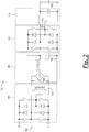
- Fig. 2 shows a DC-AC voltage converter system 100 having a first, high-frequency, DC-AC voltage converter 102 according to an embodiment out of the scope of the present invention.
- First DC-AC voltage converter 102 receives at an input 103 a first DC voltage signal.
- a first, relatively high-frequency, AC voltage signal 104 generated by a transformer 105 of first DC-AC voltage converter 102 is supplied to a DC-link 106 that converts the first AC voltage signal to a second DC voltage signal 108.
- Second DC voltage signal 108 is coupled to a second DC-AC voltage converter 110 that converts second DC voltage signal 108 to a second AC voltage signal, output AC voltage signal 112.
- Output 112 may have either low-frequency components, high-frequency components, or both low- and high-frequency components.
- An optional electrical filter 114 provides filtering of AC output voltage signal 112 to remove high-frequency components and/or limit electromagnetic interference (EMI) caused by the AC output voltage signal, resulting in a filtered AC output voltage signal 116.
- EMI electromagnetic interference
- Fig. 3 shows a DC-AC voltage converter system 200 according to another embodiment out of the scope of the present invention.
- a first AC voltage signal 202 generated by a DC-AC voltage converter 204 is supplied to an AC-AC voltage converter 206 that converts the first AC voltage signal to a second AC voltage signal, output AC voltage signal 208.
- An electrical filter 210 provides filtering of AC output voltage signal 208 to reduce EMI caused by the AC output voltage signal, resulting in a filtered AC output voltage signal 211.
- First AC voltage signal 202 is a relatively high-frequency voltage signal
- second AC voltage signal 208 is a relatively low-frequency voltage signal output from voltage converter system 200.
- voltage converter system 100 provides relatively efficient voltage conversion, but compared to voltage converter system 200 it is more complex and more expensive to produce.
- the performance of voltage converter system 200 depends in part upon the operating conditions of a transformer 212.
- Fig. 3 shows a topology wherein transformer 212 operates under regulation, with a relatively high turns ratio. In this case efficiency of voltage converter system 200 will be less and the voltage converter system will generate a relatively high level of EMI on the AC output voltage signal 208. Consequently, EMI filter 210 may require a number of relatively expensive components in order to be effective.
- Fig. 4 shows a schematic diagram of a voltage converter system 300 according to an embodiment of the present invention.
- Voltage converter system 300 is configurable for operation as either a DC-AC or an AC-DC voltage converter and is suitable for low DC input voltages (e.g., on the order of about 8-16 VDC) at power levels of up to several kilowatts.
- voltage converter system 300 overcomes the disadvantages discussed above.
- Voltage converter system 300 may be implemented with a relatively low number of active semiconductor switches.
- a transformer 302 (comprising windings 302A, 302B) functions under extremely benign conditions (i.e., conditions favorable in that root-mean-square (RMS) current and RMS voltage are favorable for relatively low transformer losses).
- RMS root-mean-square
- a first voltage converter portion, 400 shown in Fig. 5 provides pulses of DC voltage regulated from 0 volts to a predetermined maximum voltage, with a generally half-sinusoidal waveform as shown in Fig. 6 .
- a second voltage converter portion 500, shown in Fig. 7 provides electrical isolation and conversion from the pulsed DC voltage of Fig. 6 to a predetermined relatively low-frequency AC voltage signal including, without limitation, about 120 VAC at a frequency of about 50/60 Hz.
- this power stage is a combination of two types of power converters.
- the first is a ⁇ uk-type voltage converter 600, shown in Fig. 8 .
- the other is a single-ended primary inductor converter (SEPIC) voltage converter 700, shown in Fig. 9 .
- SEPIC single-ended primary inductor converter
- Both voltage converters have a number of common features. For example, each is capable of providing an output voltage from zero to several times higher than the input voltage. In addition, both are bi-directional.
- ⁇ uk-type voltage converter reverses the polarity of the input voltage while the SEPIC-type voltage converter does not.
- these characteristics may be utilized to advantage, to provide an output voltage from an appropriately paired and electrically combined ⁇ uk-type voltage converter and SEPIC-type voltage converter that is about twice the output voltage available from each voltage converter individually, each voltage converter providing about half of output power delivered by the electrically combined voltage converters.
- a further advantage of this arrangement is that doubling the output voltage in this manner aids to reduce the required primary-to-secondary winding turns ratio of isolation transformer 302.
- switches 602, 702 respectively exhibit substantially the same operating characteristics.
- inductors 604, 704 in Figs. 8 and 9 respectively exhibit substantially the same operating characteristics. Therefore, according to the present invention, these components are combined in an appropriately paired ⁇ uk-type voltage converter and SEPIC-type voltage converter to form the circuit 800 shown in Fig. 10 .
- switch 802 replaces switches 602, 702 while inductor 804 replaces the inductors 604, 704.
- switch 802 and inductor 804 are common to both the ⁇ uk-type voltage converter and the SEPIC voltage converter. This results in one less active switch and one less inductor in an appropriately paired ⁇ uk-type voltage converter and SEPIC-type voltage converter, thereby reducing voltage converter cost.
- Circuit 800 may be substituted for circuit 400 in the system of Fig. 4 .
- Cuk and SEPIC voltage converters have one common disadvantage in that neither provide forward power conversion. Rather, they use passive components such as capacitors and inductors for energy storage. Consequently, the efficiency of these voltage converters depends very much on the quality factor of the aforementioned passive components.
- the quality factor of capacitors are generally good, but the quality factor of inductors are often less than desirable and often tend to worsen under high-current and low-voltage operating conditions.
- system 800 is modified, replacing inductor 804 with an inductor/ transformer 904, as shown in the circuit 900 of Fig. 11 .
- circuit 900 is substituted for circuit 400 in the system of Fig. 4 .
- voltage converter portion 500 comprises a power stage which will provide isolation between the low voltage side and the high voltage side.
- This topology is a series-resonant voltage converter, which is bi-directional.
- the power transformer 302 in this case works under substantially benign conditions, with a generally trapezoidal voltage wave form and a generally sinusoidal current wave form.
- the transformer 302 leakage inductance is part of the resonant inductor or, optionally, may comprise the entire resonant inductor. All these features aid to keep efficiency and the commutation frequency as high as possible. This reduces the transformer size and reduces its cost, as well as total inverter cost, reducing the cost of EMI filters if used.
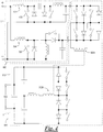
- a voltage converter 1000 is shown in Fig. 12 according to yet another embodiment of the present invention. Like voltage converters 800 and 900, according to the invention, voltage converter 1000 is substituted for circuit 400 in the system of Fig. 4 .
- Voltage converter 1000 includes a first inductor 1002 and a second inductor 1004 connected in series, the first and second inductors each having an input and an output.
- a first capacitor 1006 is electrically intermediate the first and second inductors 1002, 1004, a first terminal of the first capacitor being electrically connected to the output of the first inductor and a second terminal of the first capacitor being electrically connected to the input of the second inductor.
- a third inductor 1008 and a fourth inductor 1010 are connected in series, the third and fourth inductors each having an input and an output.
- a second capacitor 1012 is electrically intermediate the third and fourth inductors 1008, 1010, a first terminal of the second capacitor being electrically connected to the output of the third inductor and a second terminal of the second capacitor being electrically connected to the input of the fourth inductor.
- a first switch 1014 is coupled between the input of the first inductor 1002 and the output of the third inductor 1008.
- a second switch 1016 is coupled between the output of the first inductor 1002 and the input of the third inductor 1008.
- a rectifier 1018 is arranged such that an anode of the rectifier is electrically connected to the second terminal of the first capacitor 1006, a cathode of the rectifier being electrically coupled to the second terminal of the second capacitor 1012.
- a third switch 1020 is electrically connected in parallel with the rectifier 1018.
- Voltage converter 1000 is configured to receive a DC voltage signal at the inputs of the first and third inductors 1002, 1008 and to generate an AC voltage signal at the outputs of the second and fourth inductors 1004, 1010.
- Voltage converter system 1000 may further include third capacitor 1022, the third capacitor being electrically intermediate the second and fourth inductors 1004, 1010.
- a first terminal of third capacitor 1022 is electrically connected to the output of the second inductor 1004 and a second terminal of the third capacitor is electrically connected to the output of the fourth inductor 1010.
- voltage converter system 1000 has the advantage of relatively low inductor current and a low switch current, similar to the embodiment of Fig 5 , since there are two input inductors (1002 and 1008) rather than the single input inductor of the previously-described configurations, and also has a low number of switches similar to the embodiment of Fig. 10 . It should be noted that voltage converter system 1000 has more input current ripple compared to the embodiment of Fig. 5 , as half of the input current is discontinuous because it flows through the switches, it is important in this embodiment that the switches switch synchronously to eliminate voltage transients across the switches and losses.
- Inductors 1002, 1008 of voltage converter system 1000 may optionally be coupled magnetically to allow current balancing to occur.
- the current in inductor 1008 and switch 1014, and in inductor 1002 and switch 1016, may not necessarily ramp up identically as these inductor-switch pairs are independent of one another. However, when switches 1014, 1016 are opened the current flows in a complete circuit through the output (i.e., "a" and "b” of Fig. 12 ) so the current in inductors 1002, 1008 must be substantially the same. Any error will result in the energy being dumped in the switches 1014, 1016 until the currents are substantially the same. If the windings 1002, 1008 are coupled the energy can transfer between the windings until the currents are substantially the same rather than the energy being lost.
- certain inductors of voltage converter system 1000 may be wound upon a common core.
- inductors 1002, 1008 may be wound upon a common core.
- inductors 1004, 1010 may be wound upon a common core. Winding the inductors upon a common core may provide certain advantages, such as a reduction in the overall size of the inductors.
- the switches may be any suitable types of power switching components including, without limitation, semiconductors such as bipolar junction transistors, field effect transistors and thyristors.
- the diodes, capacitors, inductors and transformers shown in the accompanying figures may be any suitable types and values for a particular realization of the circuitry.
- circuits shown in the accompanying figures are simplified for purposes of explanation and are not intended to be limiting in any way. Accordingly, the circuits may include any suitable number and type of ancillary components including, without limitation, biasing, feedback and filtering components and circuitry as well as analog and/or digital monitoring, feedback and control circuitry.
Landscapes
- Engineering & Computer Science (AREA)
- Power Engineering (AREA)
- Physics & Mathematics (AREA)
- Electromagnetism (AREA)
- Dc-Dc Converters (AREA)
- Inverter Devices (AREA)
- Rectifiers (AREA)
- Arc Welding Control (AREA)
- Ac-Ac Conversion (AREA)
- Surgical Instruments (AREA)
Claims (7)
- Système convertisseur de tension (300) comprenant :une première partie de convertisseur de tension (400), configurée pour recevoir un signal de tension continue et convertir le signal de tension continue en impulsions de tension continue ;et une seconde partie de convertisseur de tension (500), configurée pour recevoir les impulsions de tension continue et convertir les impulsions de tension continue en un signal de tension alternative ;caractérisé en ce que :la première partie de convertisseur de tension (400) comprend un circuit (900) comportant :un convertisseur de tension de type Cuk comportant deux bornes d'entrée et une borne de sortie inverseuse ;un convertisseur inductif primaire à une extrémité, SEPIC, un convertisseur de tension comportant deux bornes d'entrée et une borne de sortie non inverseuse ;une paire de bornes d'entrée du système convertisseur de tension connectée aux bornes d'entrée respectives du convertisseur de tension de type Ćuk du convertisseur de tension SEPIC ;et une paire de bornes de sortie du système convertisseur de tension connectée à la borne de sortie inverseuse du convertisseur de tension de type Ćuk et à la borne de sortie non inverseuse du convertisseur de tension SEPIC ;dans lequel le convertisseur de tension de type Ćuk et le convertisseur de tension SEPIC ont un étage d'entrée commun connecté à la paire de bornes d'entrée du système convertisseur de tension, l'étage d'entrée comprenant un premier inducteur, un commutateur (902), une première borne d'entrée connectée à une première extrémité du premier inducteur, et une seconde borne d'entrée connectée à une première extrémité du commutateur (902) ;dans lequelune seconde extrémité du premier inducteur est connectée à une seconde extrémité du commutateur (902) au niveau d'un premier nœud ;le circuit (900) comprend en outre un transformateur (904), un deuxième inducteur, une première diode et une seconde diode ;dans lequelle premier inducteur représente un étage primaire du transformateur (904) ;un étage secondaire du transformateur (904) ayant des première et seconde bornes,la seconde borne étant connectée à la borne de sortie inverseuse du convertisseur de tension de type Ćuk au niveau d'un second nœud ;la première borne de l'étage secondaire du transformateur (904) étant connectée à une anode de la première diode ;une cathode de la première diode étant connectée à une première extrémité du deuxième inducteur au niveau d'un troisième nœud ;une anode de la seconde diode étant connectée au deuxième nœud ;une cathode de la seconde diode étant connectée au troisième nœud ;une seconde extrémité du deuxième inducteur étant connectée à la borne de sortie non inverseuse du convertisseur de tension SEPIC.
- Système convertisseur de tension (300) selon la revendication 1, dans lequel la première borne de l'étage secondaire du transformateur (904) est adaptée en polarité à la première borne d'entrée de l'étage d'entrée.
- Système convertisseur de tension (300) comprenant :une première partie de convertisseur de tension (400), configurée pour recevoir un signal de tension continue et convertir le signal de tension continue en impulsions de tension continue ;et une seconde partie de convertisseur de tension (500), configurée pour recevoir les impulsions de tension continue et convertir les impulsions de tension continue en un signal de tension alternative ;caractérisé en ce que :
la première de partie convertisseur de tension (400) comprend un circuit (1000) comprenant :un premier et un deuxième inducteur (1002, 1004),les premier et deuxième inducteurs (1002, 1004) ayant chacun une entrée et une sortie ;un premier condensateur (1006) connecté entre les premier et deuxième inducteurs (1002, 1004), une première borne du premier condensateur (1006) étant connectée électriquement à la sortie du premier inducteur (1002) et une seconde borne du premier condensateur (1006) étant connectée électriquement à l'entrée du deuxième inducteur (1004) ;un troisième et un quatrième inducteur (1008, 1010), les troisième et quatrième inducteurs (1008, 1010) ayant chacun une entrée et une sortie ;un deuxième condensateur (1012) connecté entre les troisième et quatrième inducteurs (1008, 1010), une première borne du deuxième condensateur (1012) étant connectée électriquement à la sortie du troisième inducteur (1008) et une seconde borne du deuxième condensateur (1012) étant connectée électriquement à l'entrée du quatrième inducteur (1010) ;un premier commutateur (1014) couplé entre l'entrée du premier inducteur (1002) et la sortie du troisième inducteur (1008) ;un deuxième commutateur (1016) couplé entre la sortie du premier inducteur (1002) etl'entrée du troisième inducteur (1008) ;un redresseur (1018) ayant une anode et une cathode, l'anode du redresseur étant connectée électriquement à la deuxième borne du premier condensateur (1006) et la cathode du redresseur étant couplée électriquement à la seconde borne du deuxième condensateur (1012), etun troisième commutateur (1020) connecté électriquement en parallèle au redresseur (1018). - Système convertisseur de tension (300) selon la revendication 3, comprenant en outre un troisième condensateur (1022), le troisième condensateur (1022) étant connecté entre les deuxième et quatrième inducteurs (1004, 1010), une première borne du troisième condensateur (1022) étant électriquement connectée à la sortie du deuxième inducteur (1004) et une seconde borne du troisième condensateur (1022) étant électriquement connectée à la sortie du quatrième inducteur (1010).
- Système convertisseur de tension (300) selon la revendication 3, dans lequel les commutateurs (1014, 1016, 1020) sont configurés pour commuter de manière synchrone.
- Système convertisseur de tension (300) selon la revendication 5, dans lequel les commutateurs (1014, 1016, 1020) sont des semi-conducteurs.
- Système convertisseur de tension (300) selon la revendication 3, dans lequel au moins deux des inducteurs (1002, 1004, 1008, 1010) sont couplés magnétiquement.
Priority Applications (1)
| Application Number | Priority Date | Filing Date | Title |
|---|---|---|---|
| EP19179088.0A EP3576283B9 (fr) | 2013-03-14 | 2014-03-14 | Topologie de circuit à conversion continu-alternatif |
Applications Claiming Priority (3)
| Application Number | Priority Date | Filing Date | Title |
|---|---|---|---|
| US201361785958P | 2013-03-14 | 2013-03-14 | |
| US14/209,282 US20140268927A1 (en) | 2013-03-14 | 2014-03-13 | Voltage converter systems |
| EP14159699.9A EP2779409A3 (fr) | 2013-03-14 | 2014-03-14 | Systèmes de convertisseur de tension |
Related Parent Applications (2)
| Application Number | Title | Priority Date | Filing Date |
|---|---|---|---|
| EP14159699.9A Division EP2779409A3 (fr) | 2013-03-14 | 2014-03-14 | Systèmes de convertisseur de tension |
| EP14159699.9A Previously-Filed-Application EP2779409A3 (fr) | 2013-03-14 | 2014-03-14 | Systèmes de convertisseur de tension |
Related Child Applications (3)
| Application Number | Title | Priority Date | Filing Date |
|---|---|---|---|
| EP19179088.0A Division EP3576283B9 (fr) | 2013-03-14 | 2014-03-14 | Topologie de circuit à conversion continu-alternatif |
| EP19179088.0A Previously-Filed-Application EP3576283B9 (fr) | 2013-03-14 | 2014-03-14 | Topologie de circuit à conversion continu-alternatif |
| EP19179088.0A Division-Into EP3576283B9 (fr) | 2013-03-14 | 2014-03-14 | Topologie de circuit à conversion continu-alternatif |
Publications (3)
| Publication Number | Publication Date |
|---|---|
| EP3038246A2 EP3038246A2 (fr) | 2016-06-29 |
| EP3038246A3 EP3038246A3 (fr) | 2016-10-12 |
| EP3038246B1 true EP3038246B1 (fr) | 2019-12-18 |
Family
ID=50272480
Family Applications (3)
| Application Number | Title | Priority Date | Filing Date |
|---|---|---|---|
| EP16153005.0A Active EP3038246B1 (fr) | 2013-03-14 | 2014-03-14 | Topologie de circuit à conversion continu-alternatif |
| EP14159699.9A Withdrawn EP2779409A3 (fr) | 2013-03-14 | 2014-03-14 | Systèmes de convertisseur de tension |
| EP19179088.0A Active EP3576283B9 (fr) | 2013-03-14 | 2014-03-14 | Topologie de circuit à conversion continu-alternatif |
Family Applications After (2)
| Application Number | Title | Priority Date | Filing Date |
|---|---|---|---|
| EP14159699.9A Withdrawn EP2779409A3 (fr) | 2013-03-14 | 2014-03-14 | Systèmes de convertisseur de tension |
| EP19179088.0A Active EP3576283B9 (fr) | 2013-03-14 | 2014-03-14 | Topologie de circuit à conversion continu-alternatif |
Country Status (3)
| Country | Link |
|---|---|
| US (3) | US20140268927A1 (fr) |
| EP (3) | EP3038246B1 (fr) |
| CA (2) | CA3045199C (fr) |
Families Citing this family (10)
| Publication number | Priority date | Publication date | Assignee | Title |
|---|---|---|---|---|
| US20140268927A1 (en) * | 2013-03-14 | 2014-09-18 | Vanner, Inc. | Voltage converter systems |
| CN105429502B (zh) * | 2015-11-20 | 2017-11-24 | 燕山大学 | 单级非隔离无电解电容双Cuk型逆变器 |
| DE102017215133A1 (de) * | 2016-08-31 | 2018-03-01 | Siemens Aktiengesellschaft | Inverter und Photovoltaikanlage |
| CN107565844B (zh) * | 2017-08-22 | 2019-09-13 | 浙江大学 | 一种单相dc-ac变换器的双向零电压开关调制方法 |
| WO2019211290A1 (fr) * | 2018-05-01 | 2019-11-07 | Danmarks Tekniske Universitet | Convertisseur ca-cc bidirectionnel de type à résonance en mode commuté et son procédé de fonctionnement |
| CN108512412B (zh) * | 2018-06-15 | 2023-06-09 | 广东机电职业技术学院 | 一种基于Sepic的单管可升降压的正负输出的DC-DC电源结构 |
| US10862401B2 (en) * | 2018-10-26 | 2020-12-08 | Lear Corporation | Tandem DC/DC converter for a vehicle battery charger |
| US11081968B2 (en) * | 2019-06-12 | 2021-08-03 | Delta Electronics, Inc. | Isolated boost converter |
| CN112436729B (zh) * | 2019-08-26 | 2022-09-27 | 哈尔滨工业大学 | 一种基于谐振式dc-dc变换器调功的感应加热装置 |
| CN113078815B (zh) * | 2020-01-03 | 2022-04-15 | 台达电子工业股份有限公司 | 电源转换系统 |
Citations (3)
| Publication number | Priority date | Publication date | Assignee | Title |
|---|---|---|---|---|
| US20100118575A1 (en) * | 2007-02-16 | 2010-05-13 | Stefan Reschenauer | Power Inverter |
| US20120228938A1 (en) * | 2009-09-11 | 2012-09-13 | Robert Bosch Gmbh | DC-AC Inverter Assembly, in Particular Solar Cell Inverter |
| WO2012146414A2 (fr) * | 2011-04-27 | 2012-11-01 | Robert Bosch Gmbh | Procédé de commande pour un onduleur et système onduleur, en particulier circuit inverseur pour cellules solaires |
Family Cites Families (28)
| Publication number | Priority date | Publication date | Assignee | Title |
|---|---|---|---|---|
| JP2539538B2 (ja) * | 1990-09-10 | 1996-10-02 | 三菱電機株式会社 | 直流交流電力変換装置 |
| US5355294A (en) * | 1992-11-25 | 1994-10-11 | General Electric Company | Unity power factor control for dual active bridge converter |
| US5442534A (en) * | 1993-02-23 | 1995-08-15 | California Institute Of Technology | Isolated multiple output Cuk converter with primary input voltage regulation feedback loop decoupled from secondary load regulation loops |
| EP0808552B1 (fr) * | 1995-12-08 | 2003-03-19 | Koninklijke Philips Electronics N.V. | Systeme de ballast |
| DE19800105A1 (de) * | 1998-01-05 | 1999-07-15 | Reinhard Kalfhaus | Strom-Spannungswandler und zugehöriger Regelkreis |
| US6330170B1 (en) * | 1999-08-27 | 2001-12-11 | Virginia Tech Intellectual Properties, Inc. | Soft-switched quasi-single-stage (QSS) bi-directional inverter/charger |
| US20060012348A1 (en) * | 2000-04-27 | 2006-01-19 | Qun Zhao | Coupled inductor DC/DC converter |
| US6515883B2 (en) * | 2001-03-28 | 2003-02-04 | Powerware Corporation | Single-stage power converter and an uninterruptible power supply using same |
| US7372709B2 (en) * | 2003-09-11 | 2008-05-13 | The Board Of Trustees Of The University Of Illinois | Power conditioning system for energy sources |
| JP4524420B2 (ja) * | 2004-07-12 | 2010-08-18 | シーメンス アクチエンゲゼルシヤフト | インバータの駆動方法およびこの方法に適するインバータ |
| JP2008517582A (ja) * | 2004-10-20 | 2008-05-22 | シーメンス ヴィディーオー オートモーティヴ コーポレイション | 電力システム、方法および装置 |
| JP2006345641A (ja) * | 2005-06-09 | 2006-12-21 | Toyota Industries Corp | Dc/ac変換回路およびdc/ac変換方法 |
| JP5208374B2 (ja) * | 2006-04-18 | 2013-06-12 | シャープ株式会社 | 系統連系パワーコンディショナおよび系統連系電源システム |
| ATE463878T1 (de) * | 2007-02-08 | 2010-04-15 | Sma Solar Technology Ag | Einrichtung zum einspeisen elektrischer energie aus einer energiequelle |
| EP2077609A3 (fr) * | 2007-12-27 | 2017-03-15 | TDK Corporation | Unité de commutation d'alimentation électrique |
| US8873252B2 (en) * | 2008-03-26 | 2014-10-28 | Enphase Energy, Inc. | Method and apparatus for extending zero-voltage switching range in a DC to DC converter |
| WO2009149556A1 (fr) * | 2008-06-13 | 2009-12-17 | Queen's University At Kingston | Ballast électronique à étage unique à gradation à facteur de puissance élevé |
| US20100019578A1 (en) * | 2008-07-26 | 2010-01-28 | Semikron Elektronik Gmbh & Co. Kg | Power Converter for Solar Electrical Current Installations and Method for Controlling it |
| US8199545B2 (en) * | 2009-05-05 | 2012-06-12 | Hamilton Sundstrand Corporation | Power-conversion control system including sliding mode controller and cycloconverter |
| WO2011020199A1 (fr) * | 2009-08-21 | 2011-02-24 | Queen's University At Kingston | Ballast électronique à facteur de puissance élevé |
| US8164275B2 (en) * | 2009-12-15 | 2012-04-24 | Tdk-Lambda Americas Inc. | Drive circuit for high-brightness light emitting diodes |
| EP2341605B1 (fr) * | 2009-12-31 | 2018-03-07 | Nxp B.V. | Niveau de correction du facteur de puissance |
| US8559193B2 (en) * | 2010-01-22 | 2013-10-15 | The Board Of Trustees Of The University Of Illinois | Zero-voltage-switching scheme for high-frequency converter |
| US9762115B2 (en) * | 2011-02-03 | 2017-09-12 | Viswa N. Sharma | Bidirectional multimode power converter |
| US20120290145A1 (en) * | 2011-05-10 | 2012-11-15 | Madhuwanti Joshi | Single-stage grid-connected solar inverter for distributed reactive power generation |
| US9379640B2 (en) * | 2011-06-23 | 2016-06-28 | The Board Of Trustees Of The University Of Illinois | Scalable single-stage differential power converter |
| DE102011051482A1 (de) * | 2011-06-30 | 2013-01-03 | Sma Solar Technology Ag | Brückenschaltungsanordnung und Betriebsverfahren für einen Spannungswandler und Spannungswandler |
| US20140268927A1 (en) * | 2013-03-14 | 2014-09-18 | Vanner, Inc. | Voltage converter systems |
-
2014
- 2014-03-13 US US14/209,282 patent/US20140268927A1/en not_active Abandoned
- 2014-03-14 EP EP16153005.0A patent/EP3038246B1/fr active Active
- 2014-03-14 CA CA3045199A patent/CA3045199C/fr active Active
- 2014-03-14 EP EP14159699.9A patent/EP2779409A3/fr not_active Withdrawn
- 2014-03-14 CA CA2846668A patent/CA2846668C/fr active Active
- 2014-03-14 EP EP19179088.0A patent/EP3576283B9/fr active Active
-
2016
- 2016-01-22 US US15/004,433 patent/US9692313B1/en active Active
-
2017
- 2017-03-22 US US15/466,470 patent/US9906169B1/en active Active
Patent Citations (3)
| Publication number | Priority date | Publication date | Assignee | Title |
|---|---|---|---|---|
| US20100118575A1 (en) * | 2007-02-16 | 2010-05-13 | Stefan Reschenauer | Power Inverter |
| US20120228938A1 (en) * | 2009-09-11 | 2012-09-13 | Robert Bosch Gmbh | DC-AC Inverter Assembly, in Particular Solar Cell Inverter |
| WO2012146414A2 (fr) * | 2011-04-27 | 2012-11-01 | Robert Bosch Gmbh | Procédé de commande pour un onduleur et système onduleur, en particulier circuit inverseur pour cellules solaires |
Also Published As
| Publication number | Publication date |
|---|---|
| US9906169B1 (en) | 2018-02-27 |
| US20140268927A1 (en) | 2014-09-18 |
| EP3576283A1 (fr) | 2019-12-04 |
| CA2846668C (fr) | 2021-10-19 |
| EP2779409A2 (fr) | 2014-09-17 |
| EP3576283B1 (fr) | 2020-07-01 |
| CA3045199C (fr) | 2020-10-20 |
| CA2846668A1 (fr) | 2014-09-14 |
| EP3038246A2 (fr) | 2016-06-29 |
| EP2779409A3 (fr) | 2015-11-18 |
| EP3576283B9 (fr) | 2020-10-07 |
| US9692313B1 (en) | 2017-06-27 |
| CA3045199A1 (fr) | 2014-09-14 |
| EP3038246A3 (fr) | 2016-10-12 |
Similar Documents
| Publication | Publication Date | Title |
|---|---|---|
| EP3038246B1 (fr) | Topologie de circuit à conversion continu-alternatif | |
| EP3257146B1 (fr) | Convertisseur cc-cc | |
| Tofoli et al. | Novel nonisolated high-voltage gain dc–dc converters based on 3SSC and VMC | |
| US9490694B2 (en) | Hybrid resonant bridgeless AC-DC power factor correction converter | |
| JP4322250B2 (ja) | トランスレス型系統連係電力変換回路 | |
| TWI536709B (zh) | 電源系統及供電方法 | |
| EP2571154B1 (fr) | Onduleur PV avec convertisseurs à transfer indirect avec entrées en parallèle er sorties en série pour alimentation d'un pont complet | |
| CN101689760B (zh) | 用于将电能馈送到供电系统的变换器 | |
| US20120155139A1 (en) | Electrical Energy Conversion Circuit Device | |
| CN102638213A (zh) | 双向降压-升压功率变换器、电起动机-发电机系统及方法 | |
| US20140049998A1 (en) | DC to AC Power Converter | |
| CN1808832B (zh) | 一种适用于中大功率不间断电源的电路装置 | |
| Narimani et al. | A new interleaved three-phase single-stage PFC AC–DC converter with flying capacitor | |
| KR20190115364A (ko) | 단상 및 3상 겸용 충전기 | |
| JP2014522231A (ja) | 結合インダクタンスを備えるインバータ | |
| US11764692B2 (en) | DC to DC boost converter | |
| Srinivas | Integrated Magnetics based Dual Output AC/DC Flyback Converter Topology with Active Front-End Power Factor Correction for Low Power Medical Applications | |
| KR20180091543A (ko) | 역률 개선 컨버터 | |
| Reddivari et al. | Differential mode gamma source inverter with reduced switching stresses | |
| Sagehashi et al. | One-inductor single-stage differential boost inverter operated in discontinuous current mode for single-phase grid-tied photovoltaic system | |
| Shirshin et al. | Analysis of Operating Modes of a Bidirectional Quasiresonant DC Voltage Converter as Employed in Energy Storage Systems | |
| JP2025120703A (ja) | コンバータ回路 | |
| CN113691119A (zh) | 三相功率因素校正装置 |
Legal Events
| Date | Code | Title | Description |
|---|---|---|---|
| PUAI | Public reference made under article 153(3) epc to a published international application that has entered the european phase |
Free format text: ORIGINAL CODE: 0009012 |
|
| 17P | Request for examination filed |
Effective date: 20160127 |
|
| AC | Divisional application: reference to earlier application |
Ref document number: 2779409 Country of ref document: EP Kind code of ref document: P |
|
| AK | Designated contracting states |
Kind code of ref document: A2 Designated state(s): AL AT BE BG CH CY CZ DE DK EE ES FI FR GB GR HR HU IE IS IT LI LT LU LV MC MK MT NL NO PL PT RO RS SE SI SK SM TR |
|
| AX | Request for extension of the european patent |
Extension state: BA ME |
|
| PUAL | Search report despatched |
Free format text: ORIGINAL CODE: 0009013 |
|
| AK | Designated contracting states |
Kind code of ref document: A3 Designated state(s): AL AT BE BG CH CY CZ DE DK EE ES FI FR GB GR HR HU IE IS IT LI LT LU LV MC MK MT NL NO PL PT RO RS SE SI SK SM TR |
|
| AX | Request for extension of the european patent |
Extension state: BA ME |
|
| RIC1 | Information provided on ipc code assigned before grant |
Ipc: H02M 7/48 20070101AFI20160906BHEP Ipc: H02M 7/06 20060101ALI20160906BHEP Ipc: H02M 7/797 20060101ALI20160906BHEP Ipc: H02M 7/537 20060101ALI20160906BHEP Ipc: H02M 7/515 20070101ALI20160906BHEP |
|
| STAA | Information on the status of an ep patent application or granted ep patent |
Free format text: STATUS: EXAMINATION IS IN PROGRESS |
|
| 17Q | First examination report despatched |
Effective date: 20180115 |
|
| REG | Reference to a national code |
Ref country code: DE Ref legal event code: R079 Ref document number: 602014058787 Country of ref document: DE Free format text: PREVIOUS MAIN CLASS: H02M0007480000 Ipc: H02M0007537000 |
|
| GRAP | Despatch of communication of intention to grant a patent |
Free format text: ORIGINAL CODE: EPIDOSNIGR1 |
|
| STAA | Information on the status of an ep patent application or granted ep patent |
Free format text: STATUS: GRANT OF PATENT IS INTENDED |
|
| RIC1 | Information provided on ipc code assigned before grant |
Ipc: H02M 7/48 20070101ALI20190822BHEP Ipc: H02M 3/155 20060101ALN20190822BHEP Ipc: H02M 5/458 20060101ALI20190822BHEP Ipc: H02M 7/797 20060101ALI20190822BHEP Ipc: H02M 7/72 20060101ALI20190822BHEP Ipc: H02M 1/44 20070101ALI20190822BHEP Ipc: H02M 3/28 20060101ALI20190822BHEP Ipc: H02M 1/00 20060101ALN20190822BHEP Ipc: H02M 7/537 20060101AFI20190822BHEP Ipc: H02M 3/00 20060101ALN20190822BHEP |
|
| INTG | Intention to grant announced |
Effective date: 20190919 |
|
| RIN1 | Information on inventor provided before grant (corrected) |
Inventor name: COOK, ALEXANDER Inventor name: ISURIN, ALEXANDER |
|
| GRAS | Grant fee paid |
Free format text: ORIGINAL CODE: EPIDOSNIGR3 |
|
| GRAA | (expected) grant |
Free format text: ORIGINAL CODE: 0009210 |
|
| STAA | Information on the status of an ep patent application or granted ep patent |
Free format text: STATUS: THE PATENT HAS BEEN GRANTED |
|
| AC | Divisional application: reference to earlier application |
Ref document number: 2779409 Country of ref document: EP Kind code of ref document: P |
|
| AK | Designated contracting states |
Kind code of ref document: B1 Designated state(s): AL AT BE BG CH CY CZ DE DK EE ES FI FR GB GR HR HU IE IS IT LI LT LU LV MC MK MT NL NO PL PT RO RS SE SI SK SM TR |
|
| REG | Reference to a national code |
Ref country code: CH Ref legal event code: EP |
|
| REG | Reference to a national code |
Ref country code: IE Ref legal event code: FG4D |
|
| REG | Reference to a national code |
Ref country code: DE Ref legal event code: R096 Ref document number: 602014058787 Country of ref document: DE |
|
| REG | Reference to a national code |
Ref country code: AT Ref legal event code: REF Ref document number: 1215668 Country of ref document: AT Kind code of ref document: T Effective date: 20200115 |
|
| REG | Reference to a national code |
Ref country code: NL Ref legal event code: MP Effective date: 20191218 |
|
| PG25 | Lapsed in a contracting state [announced via postgrant information from national office to epo] |
Ref country code: FI Free format text: LAPSE BECAUSE OF FAILURE TO SUBMIT A TRANSLATION OF THE DESCRIPTION OR TO PAY THE FEE WITHIN THE PRESCRIBED TIME-LIMIT Effective date: 20191218 Ref country code: LT Free format text: LAPSE BECAUSE OF FAILURE TO SUBMIT A TRANSLATION OF THE DESCRIPTION OR TO PAY THE FEE WITHIN THE PRESCRIBED TIME-LIMIT Effective date: 20191218 Ref country code: GR Free format text: LAPSE BECAUSE OF FAILURE TO SUBMIT A TRANSLATION OF THE DESCRIPTION OR TO PAY THE FEE WITHIN THE PRESCRIBED TIME-LIMIT Effective date: 20200319 Ref country code: NO Free format text: LAPSE BECAUSE OF FAILURE TO SUBMIT A TRANSLATION OF THE DESCRIPTION OR TO PAY THE FEE WITHIN THE PRESCRIBED TIME-LIMIT Effective date: 20200318 Ref country code: SE Free format text: LAPSE BECAUSE OF FAILURE TO SUBMIT A TRANSLATION OF THE DESCRIPTION OR TO PAY THE FEE WITHIN THE PRESCRIBED TIME-LIMIT Effective date: 20191218 Ref country code: LV Free format text: LAPSE BECAUSE OF FAILURE TO SUBMIT A TRANSLATION OF THE DESCRIPTION OR TO PAY THE FEE WITHIN THE PRESCRIBED TIME-LIMIT Effective date: 20191218 Ref country code: BG Free format text: LAPSE BECAUSE OF FAILURE TO SUBMIT A TRANSLATION OF THE DESCRIPTION OR TO PAY THE FEE WITHIN THE PRESCRIBED TIME-LIMIT Effective date: 20200318 |
|
| REG | Reference to a national code |
Ref country code: LT Ref legal event code: MG4D |
|
| PG25 | Lapsed in a contracting state [announced via postgrant information from national office to epo] |
Ref country code: RS Free format text: LAPSE BECAUSE OF FAILURE TO SUBMIT A TRANSLATION OF THE DESCRIPTION OR TO PAY THE FEE WITHIN THE PRESCRIBED TIME-LIMIT Effective date: 20191218 Ref country code: HR Free format text: LAPSE BECAUSE OF FAILURE TO SUBMIT A TRANSLATION OF THE DESCRIPTION OR TO PAY THE FEE WITHIN THE PRESCRIBED TIME-LIMIT Effective date: 20191218 |
|
| PG25 | Lapsed in a contracting state [announced via postgrant information from national office to epo] |
Ref country code: AL Free format text: LAPSE BECAUSE OF FAILURE TO SUBMIT A TRANSLATION OF THE DESCRIPTION OR TO PAY THE FEE WITHIN THE PRESCRIBED TIME-LIMIT Effective date: 20191218 |
|
| PG25 | Lapsed in a contracting state [announced via postgrant information from national office to epo] |
Ref country code: EE Free format text: LAPSE BECAUSE OF FAILURE TO SUBMIT A TRANSLATION OF THE DESCRIPTION OR TO PAY THE FEE WITHIN THE PRESCRIBED TIME-LIMIT Effective date: 20191218 Ref country code: RO Free format text: LAPSE BECAUSE OF FAILURE TO SUBMIT A TRANSLATION OF THE DESCRIPTION OR TO PAY THE FEE WITHIN THE PRESCRIBED TIME-LIMIT Effective date: 20191218 Ref country code: CZ Free format text: LAPSE BECAUSE OF FAILURE TO SUBMIT A TRANSLATION OF THE DESCRIPTION OR TO PAY THE FEE WITHIN THE PRESCRIBED TIME-LIMIT Effective date: 20191218 Ref country code: PT Free format text: LAPSE BECAUSE OF FAILURE TO SUBMIT A TRANSLATION OF THE DESCRIPTION OR TO PAY THE FEE WITHIN THE PRESCRIBED TIME-LIMIT Effective date: 20200513 Ref country code: NL Free format text: LAPSE BECAUSE OF FAILURE TO SUBMIT A TRANSLATION OF THE DESCRIPTION OR TO PAY THE FEE WITHIN THE PRESCRIBED TIME-LIMIT Effective date: 20191218 |
|
| PG25 | Lapsed in a contracting state [announced via postgrant information from national office to epo] |
Ref country code: IS Free format text: LAPSE BECAUSE OF FAILURE TO SUBMIT A TRANSLATION OF THE DESCRIPTION OR TO PAY THE FEE WITHIN THE PRESCRIBED TIME-LIMIT Effective date: 20200418 Ref country code: SK Free format text: LAPSE BECAUSE OF FAILURE TO SUBMIT A TRANSLATION OF THE DESCRIPTION OR TO PAY THE FEE WITHIN THE PRESCRIBED TIME-LIMIT Effective date: 20191218 Ref country code: SM Free format text: LAPSE BECAUSE OF FAILURE TO SUBMIT A TRANSLATION OF THE DESCRIPTION OR TO PAY THE FEE WITHIN THE PRESCRIBED TIME-LIMIT Effective date: 20191218 |
|
| REG | Reference to a national code |
Ref country code: DE Ref legal event code: R097 Ref document number: 602014058787 Country of ref document: DE |
|
| REG | Reference to a national code |
Ref country code: AT Ref legal event code: MK05 Ref document number: 1215668 Country of ref document: AT Kind code of ref document: T Effective date: 20191218 |
|
| PLBE | No opposition filed within time limit |
Free format text: ORIGINAL CODE: 0009261 |
|
| STAA | Information on the status of an ep patent application or granted ep patent |
Free format text: STATUS: NO OPPOSITION FILED WITHIN TIME LIMIT |
|
| PG25 | Lapsed in a contracting state [announced via postgrant information from national office to epo] |
Ref country code: ES Free format text: LAPSE BECAUSE OF FAILURE TO SUBMIT A TRANSLATION OF THE DESCRIPTION OR TO PAY THE FEE WITHIN THE PRESCRIBED TIME-LIMIT Effective date: 20191218 Ref country code: MC Free format text: LAPSE BECAUSE OF FAILURE TO SUBMIT A TRANSLATION OF THE DESCRIPTION OR TO PAY THE FEE WITHIN THE PRESCRIBED TIME-LIMIT Effective date: 20191218 Ref country code: DK Free format text: LAPSE BECAUSE OF FAILURE TO SUBMIT A TRANSLATION OF THE DESCRIPTION OR TO PAY THE FEE WITHIN THE PRESCRIBED TIME-LIMIT Effective date: 20191218 |
|
| REG | Reference to a national code |
Ref country code: CH Ref legal event code: PL |
|
| 26N | No opposition filed |
Effective date: 20200921 |
|
| PG25 | Lapsed in a contracting state [announced via postgrant information from national office to epo] |
Ref country code: SI Free format text: LAPSE BECAUSE OF FAILURE TO SUBMIT A TRANSLATION OF THE DESCRIPTION OR TO PAY THE FEE WITHIN THE PRESCRIBED TIME-LIMIT Effective date: 20191218 Ref country code: AT Free format text: LAPSE BECAUSE OF FAILURE TO SUBMIT A TRANSLATION OF THE DESCRIPTION OR TO PAY THE FEE WITHIN THE PRESCRIBED TIME-LIMIT Effective date: 20191218 |
|
| REG | Reference to a national code |
Ref country code: BE Ref legal event code: MM Effective date: 20200331 |
|
| PG25 | Lapsed in a contracting state [announced via postgrant information from national office to epo] |
Ref country code: LU Free format text: LAPSE BECAUSE OF NON-PAYMENT OF DUE FEES Effective date: 20200314 |
|
| PG25 | Lapsed in a contracting state [announced via postgrant information from national office to epo] |
Ref country code: LI Free format text: LAPSE BECAUSE OF NON-PAYMENT OF DUE FEES Effective date: 20200331 Ref country code: IE Free format text: LAPSE BECAUSE OF NON-PAYMENT OF DUE FEES Effective date: 20200314 Ref country code: CH Free format text: LAPSE BECAUSE OF NON-PAYMENT OF DUE FEES Effective date: 20200331 Ref country code: FR Free format text: LAPSE BECAUSE OF NON-PAYMENT OF DUE FEES Effective date: 20200331 Ref country code: IT Free format text: LAPSE BECAUSE OF FAILURE TO SUBMIT A TRANSLATION OF THE DESCRIPTION OR TO PAY THE FEE WITHIN THE PRESCRIBED TIME-LIMIT Effective date: 20191218 |
|
| PG25 | Lapsed in a contracting state [announced via postgrant information from national office to epo] |
Ref country code: PL Free format text: LAPSE BECAUSE OF FAILURE TO SUBMIT A TRANSLATION OF THE DESCRIPTION OR TO PAY THE FEE WITHIN THE PRESCRIBED TIME-LIMIT Effective date: 20191218 Ref country code: BE Free format text: LAPSE BECAUSE OF NON-PAYMENT OF DUE FEES Effective date: 20200331 |
|
| PG25 | Lapsed in a contracting state [announced via postgrant information from national office to epo] |
Ref country code: TR Free format text: LAPSE BECAUSE OF FAILURE TO SUBMIT A TRANSLATION OF THE DESCRIPTION OR TO PAY THE FEE WITHIN THE PRESCRIBED TIME-LIMIT Effective date: 20191218 Ref country code: MT Free format text: LAPSE BECAUSE OF FAILURE TO SUBMIT A TRANSLATION OF THE DESCRIPTION OR TO PAY THE FEE WITHIN THE PRESCRIBED TIME-LIMIT Effective date: 20191218 Ref country code: CY Free format text: LAPSE BECAUSE OF FAILURE TO SUBMIT A TRANSLATION OF THE DESCRIPTION OR TO PAY THE FEE WITHIN THE PRESCRIBED TIME-LIMIT Effective date: 20191218 |
|
| PG25 | Lapsed in a contracting state [announced via postgrant information from national office to epo] |
Ref country code: MK Free format text: LAPSE BECAUSE OF FAILURE TO SUBMIT A TRANSLATION OF THE DESCRIPTION OR TO PAY THE FEE WITHIN THE PRESCRIBED TIME-LIMIT Effective date: 20191218 |
|
| PGFP | Annual fee paid to national office [announced via postgrant information from national office to epo] |
Ref country code: GB Payment date: 20260106 Year of fee payment: 13 |
|
| PGFP | Annual fee paid to national office [announced via postgrant information from national office to epo] |
Ref country code: DE Payment date: 20260102 Year of fee payment: 13 |