EP3038280A1 - Système de communication radio et équipement utilisateur - Google Patents
Système de communication radio et équipement utilisateur Download PDFInfo
- Publication number
- EP3038280A1 EP3038280A1 EP14837523.1A EP14837523A EP3038280A1 EP 3038280 A1 EP3038280 A1 EP 3038280A1 EP 14837523 A EP14837523 A EP 14837523A EP 3038280 A1 EP3038280 A1 EP 3038280A1
- Authority
- EP
- European Patent Office
- Prior art keywords
- base station
- user device
- signal
- downlink transmission
- transmission power
- Prior art date
- Legal status (The legal status is an assumption and is not a legal conclusion. Google has not performed a legal analysis and makes no representation as to the accuracy of the status listed.)
- Granted
Links
Images





Classifications
-
- H—ELECTRICITY
- H04—ELECTRIC COMMUNICATION TECHNIQUE
- H04W—WIRELESS COMMUNICATION NETWORKS
- H04W52/00—Power management, e.g. Transmission Power Control [TPC] or power classes
- H04W52/04—Transmission power control [TPC]
- H04W52/18—TPC being performed according to specific parameters
- H04W52/24—TPC being performed according to specific parameters using SIR [Signal to Interference Ratio] or other wireless path parameters
- H04W52/243—TPC being performed according to specific parameters using SIR [Signal to Interference Ratio] or other wireless path parameters taking into account interferences
-
- H—ELECTRICITY
- H04—ELECTRIC COMMUNICATION TECHNIQUE
- H04W—WIRELESS COMMUNICATION NETWORKS
- H04W52/00—Power management, e.g. Transmission Power Control [TPC] or power classes
- H04W52/04—Transmission power control [TPC]
- H04W52/18—TPC being performed according to specific parameters
- H04W52/28—TPC being performed according to specific parameters using user profile, e.g. mobile speed, priority or network state, e.g. standby, idle or non-transmission
- H04W52/283—Power depending on the position of the mobile
-
- H—ELECTRICITY
- H04—ELECTRIC COMMUNICATION TECHNIQUE
- H04B—TRANSMISSION
- H04B1/00—Details of transmission systems, not covered by a single one of groups H04B3/00 - H04B13/00; Details of transmission systems not characterised by the medium used for transmission
- H04B1/69—Spread spectrum techniques
- H04B1/707—Spread spectrum techniques using direct sequence modulation
- H04B1/7097—Interference-related aspects
- H04B1/7103—Interference-related aspects the interference being multiple access interference
- H04B1/7107—Subtractive interference cancellation
- H04B1/71072—Successive interference cancellation
-
- H—ELECTRICITY
- H04—ELECTRIC COMMUNICATION TECHNIQUE
- H04J—MULTIPLEX COMMUNICATION
- H04J11/00—Orthogonal multiplex systems, e.g. using WALSH codes
- H04J11/0023—Interference mitigation or co-ordination
- H04J11/0026—Interference mitigation or co-ordination of multi-user interference
- H04J11/0036—Interference mitigation or co-ordination of multi-user interference at the receiver
- H04J11/004—Interference mitigation or co-ordination of multi-user interference at the receiver using regenerative subtractive interference cancellation
-
- H—ELECTRICITY
- H04—ELECTRIC COMMUNICATION TECHNIQUE
- H04W—WIRELESS COMMUNICATION NETWORKS
- H04W52/00—Power management, e.g. Transmission Power Control [TPC] or power classes
- H04W52/04—Transmission power control [TPC]
- H04W52/18—TPC being performed according to specific parameters
- H04W52/28—TPC being performed according to specific parameters using user profile, e.g. mobile speed, priority or network state, e.g. standby, idle or non-transmission
-
- H—ELECTRICITY
- H04—ELECTRIC COMMUNICATION TECHNIQUE
- H04J—MULTIPLEX COMMUNICATION
- H04J11/00—Orthogonal multiplex systems, e.g. using WALSH codes
- H04J11/0023—Interference mitigation or co-ordination
- H04J11/005—Interference mitigation or co-ordination of intercell interference
Definitions
- the present invention relates to a radio communication system and to a user device.
- Non-orthogonal multiple access has been proposed as a scheme for communication between base stations and user devices (e.g., see Patent Document 1).
- NOMA non-orthogonal multiple access
- the same radio resource is allocated to different user devices. More specifically, a single frequency is simultaneously allocated to different user devices.
- a base station transmits a signal with high transmission power to a user device with large path loss or low reception SINR (signal-to-interference plus noise power ratio) (that is, in general, a user device located at the edge of a cell area).
- SINR signal-to-interference plus noise power ratio
- the base station transmits a signal with low transmission power. Signals to be received by each user device are therefore subject to interference from signals directed to other user devices.
- each user device utilizes a power difference to demodulate a signal directed to the user device. Specifically, each user device first demodulates a signal having the highest reception power. Since the demodulated signal is a signal directed to a user device that is located at the farthest edge of the cell area or that is with the lowest reception SINR, the user device located at the farthest edge of the cell area or with the lowest reception SINR finishes demodulation. Each of the other user devices uses an interference canceller to eliminate, from the received signals, an interfering component corresponding to the demodulated signal. Each of the other user devices then demodulates a signal having the second highest reception power.
- the demodulated signal is a signal directed to a user device that is located at the second farthest edge of the cell area or that is with the second lowest reception SINR
- the user device located at the second farthest edge of the cell area or with the second lowest reception SINR finishes demodulation.
- a combination of non-orthogonal multiple access with orthogonal multiple access can increase the capacity of a mobile communication network in comparison with the use of orthogonal multiple access alone. That is, while the use of orthogonal multiple access alone does not allow simultaneous allocation of a radio resource (e.g., a frequency) to multiple user devices, a combination of non-orthogonal multiple access and orthogonal multiple access will allow simultaneous allocation of a radio resource to multiple user devices.
- a radio resource e.g., a frequency
- Interference rejection combining is a technique for downlink communication in which a user device assigns weights to signals captured by receiving antennae so as to suppress interference, to a desired radio beam from a serving base station (desired base station), from an interfering radio beam from an interfering base station.
- IRC particularly improves the reception quality of a desired signal carried on a desired radio beam when a user device is located near a boundary of a serving cell area (i.e., a cell area of a desired base station) and is subject to a strong interfering radio beam from another base station (interfering base station) adjacent to the desired base station.
- a serving cell area i.e., a cell area of a desired base station
- interfering base station another base station
- no radio communication system has been proposed that uses non-orthogonal multiple access and in which a user device can execute interference rejection combining and can appropriately process radio signals that include non-orthogonal signals.
- the present invention therefore provides: a radio communication system that uses non-orthogonal multiple access and in which a user device can execute interference rejection combining and can appropriately process radio signals that include non-orthogonal signals; and a user device therefor.
- a radio communication system includes base stations and user devices.
- Each base station includes: a downlink transmission power determiner that determines, according to parameters associated with locations of user devices that are connected to the base station, downlink transmission power for downlink transmission to each of these user devices connected to the base station; a radio signal transmitter that transmits a radio signal in which non-orthogonal signals that are not orthogonal to each other are mixed, each of the non-orthogonal signals being transmitted with the corresponding downlink transmission power determined by the downlink transmission power determiner, each of the non-orthogonal signals being directed to a corresponding one of the user devices connected to the base station; and an information notifier that notifies each of the user devices connected to the base station of information associated with at least one of a location of the user device and the downlink transmission power for the user device.
- Each user device includes: a radio signal receiver that receives, from a desired base station to which the user device is connected, a radio signal including non-orthogonal signals that are not orthogonal to each other; an interference rejection combining processor that suppresses an interference signal component received from an interfering base station to which the user device is not connected, the interference signal component being in a non-orthogonal signal in the radio signal received by the radio signal receiver; a demodulator that demodulates the non-orthogonal signal in which the interference signal component has been suppressed by the interference rejection combining processor; a location recognizer that recognizes, based on the information transmitted from the desired base station, a parameter associated with the location of the user device; and a non-orthogonal signal canceller that, in a case in which the location recognizer recognizes that the user device is located within a cell area of the desired base station and is not located nearest to a boundary of the cell area, cancels, from the radio signal, the non-orthogonal signal demodulated by the de
- the demodulator demodulates, as a signal directed to the user device, the radio signal in which the interference signal component has been suppressed by the interference rejection combining processor, and the non-orthogonal signal canceller does not operate.
- the interference rejection combining processor suppresses an interference signal component in a non-orthogonal signal outputted from the non-orthogonal signal canceller and the demodulator demodulates the non-orthogonal signal in which the interference signal component has been suppressed by the interference rejection combining processor.
- a user device communicates with a desired base station.
- the user device includes: a radio signal receiver that receives, from the desired base station, a radio signal in which non-orthogonal signals that are not orthogonal to each other are mixed, each of the non-orthogonal signals being directed to a corresponding one of user devices that are connected to the desired base station, the non-orthogonal signals being different in power according to parameters associated with locations of these user devices connected to the desired base station; an interference rejection combining processor that suppresses an interference signal component received from an interfering base station to which the user device is not connected, the interference signal component being in a non-orthogonal signal in the radio signal received by the radio signal receiver; a demodulator that demodulates the non-orthogonal signal in which the interference signal component has been suppressed by the interference rejection combining processor; a location recognizer that recognizes, based on information transmitted from the desired base station, a parameter associated with a location of the user device, the information being associated with
- the demodulator demodulates, as a signal directed to the user device, the radio signal in which the interference signal component has been suppressed by the interference rejection combining processor, and the non-orthogonal signal canceller does not operate.
- the interference rejection combining processor suppresses an interference signal component in a non-orthogonal signal outputted from the non-orthogonal signal canceller and the demodulator demodulates the non-orthogonal signal in which the interference signal component has been suppressed by the interference rejection combining processor.
- the user device recognizes, based on information that is transmitted from the desired base station and is associated with at least one of the location of the user device and the downlink transmission power for the user device, a parameter associated with the location of the user device.
- the demodulator demodulates, as a signal directed to the user device, the radio signal in which the interference signal component has been suppressed by the interference rejection combining processor, and the non-orthogonal signal canceller does not operate. That is, in this case, the user device executes interference rejection combining, and the user device demodulates the radio signal without cancelling a non-orthogonal signal directed to another user device connected to the desired base station.
- the interference rejection combining processor of the user device suppresses an interference signal component that is in the radio signal and is received from an interfering base station
- the demodulator demodulates a non-orthogonal signal in which the interference signal component has been suppressed by the interference rejection combining processor
- the non-orthogonal signal canceller cancels, from the radio signal, the non-orthogonal signal demodulated by the demodulator.
- the interference rejection combining processor suppresses an interference signal component in a non-orthogonal signal outputted from the non-orthogonal signal canceller, and the demodulator demodulates the non-orthogonal signal in which the interference signal component has been suppressed by the interference rejection combining processor. That is, in this case, the user device repeats interference rejection combining and cancellation of a non-orthogonal signal directed to another user device connected to the desired base station, until the demodulator demodulates the signal directed to the user device.
- the present invention achieves non-orthogonal multiple access in which a user device can execute interference rejection combining and appropriately process a radio signal that includes non-orthogonal signals.
- the user device can recognize a parameter associated with the location of the user device, and based on the parameter associated with the location, the user device can selectively execute interference rejection combining and appropriate processes for demodulation of a non-orthogonal signal.
- a base station 1 communicates with user devices (i.e., pieces of user equipment or UE) 100 to 102.
- reference sign 1a denotes a cell area of the base station 1.
- the UE 102 is located at the edge of the cell area, that is, nearest the boundary of the cell area 1a.
- the UE 102 is farthest away from the base station 1 and has the greatest path loss (or the lowest reception SINR).
- the UE 100 is located near the center of the cell area 1a.
- the UE 100 is nearest to the base station 1 and has the smallest path loss (or the highest reception SINR).
- the UE 101 is nearer to the base station 1 than the UE 102 and farther away from the base station 1 than the UE 100.
- FIG. 2 is a diagram illustrating an example of downlink transmission power allocation to each UE by a base station in non-orthogonal multiple access.
- the base station 1 performs downlink transmission to the UEs 100 to 102 by simultaneously using the same frequency. That is, the same frequency and the same time are allocated to the UEs 100 to 102.
- the base station 1 uses the highest downlink transmission power for transmission to the UE 102, which is located farthest away from the base station 1.
- the base station 1 uses the lowest downlink transmission power for transmission to the UE 100, which is located nearest to the base station 1.
- Non-orthogonal multiple access can be combined with orthogonal multiple access, and a frequency that is different from the frequency allocated to the UEs 100 to 102 may be allocated to UEs other than the UEs 100 to 102.
- the number of UEs to which the same frequency is simultaneously allocated i.e., the number of UEs multiplexed in NOMA is not limited to 3; it may be 2, 4, or more than 4.
- a signal having the highest reception power is a signal directed to the UE 102 and a signal having the lowest reception power is a signal directed to the UE 100.
- Each of the UEs 100 to 102 first demodulates the signal having the highest reception power. Since the demodulated signal is a signal directed to the UE 102, which is located nearest to the boundary of the cell area 1a, the UE 102 finishes demodulation and uses the demodulated signal.
- Each of the other UEs 100 and 101 eliminates an interfering component corresponding to the demodulated signal from the received signal using an interference canceller and demodulates a signal having the second highest reception power.
- the demodulated signal is a signal for the UE 101, which is located second nearest to the boundary of the cell area 1a, the UE 101 finishes demodulation and uses the demodulated signal.
- every one of the UEs 100 to 102 can demodulate a signal directed to its own UE.
- a UE cancels a signal that is transmitted from the desired base station 1 to another UE until the UE demodulates a signal directed to the UE.
- a radio communication network includes base stations 1 and 2.
- the base station 1 communicates with UEs 100 and 101, and the base station 2 communicates with UEs 120 and 121.
- reference sign 2a denotes a cell area of the base station 2.
- Radio waves that are received from the desired base station 1 by the UEs connected to the base station 1 are subject to interference from radio waves that are transmitted from the base station 2 and are of the same frequency.
- Radio waves that are received from the desired base station 2 by the UEs connected to the base station 2 are subject to interference from radio waves that are transmitted from the base station 1 and are of the same frequency.
- a UE located near a boundary of a cell area of a desired base station is susceptible to an interfering radio beam from another base station adjacent to the desired base station.
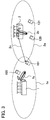
- the UE 101 which is located near the boundary of the serving cell area (i.e., the cell area of the desired base station 1) 1a, is highly susceptible to an interfering radio beam from the other base station 2 (interfering base station), which is adjacent to the desired base station 1.
- FIG. 3 schematically illustrates the shape of a beam 1b generated by the desired base station 1 and the shape of a beam 2b generated by the interfering base station 2.
- a portion of the beam 2b generated by the interfering base station 2 i.e., the beam for a downlink channel to another UE (e.g., the UE 120), can become a cause of an interference signal 2c to the UE 101.
- Interference rejection combining is a technique in which a UE calculates a weighting coefficient (reception weight) using an MMSE (minimum mean square error) algorithm, applies the reception weight to each signal that is received by each receiving antenna of the UE, and thereby cancels an interference signal transmitted from an interfering base station.
- MMSE minimum mean square error
- the present invention relates to a radio communication system, such as that illustrated in FIG. 3 , which includes base stations and multiple UEs.
- the present invention relates to a radio communication system to which non-orthogonal multiple access (NOMA) is applied and in which each UE can execute interference rejection combining (IRC) and appropriately process a radio signal that includes non-orthogonal signals.
- NOMA non-orthogonal multiple access
- IRC interference rejection combining
- the base station determines downlink transmission power P k for each UE using, for example, Formula (1) below.
- P is the sum of downlink transmission power to all UEs that simultaneously use the same frequency (total downlink transmission power).
- the subscript k of each parameter identifies a UE for which the downlink transmission power P k is determined, and the subscript i of each parameter identifies a UE in summation in Formula (1).
- K is the number of UEs that simultaneously use the same frequency.
- the term h indicates a downlink channel coefficient for a UE, and N indicates a sum of thermal noise power and interfering power from another base station at each UE.
- hi 2 N i corresponds to an SINR (signal-to-interference plus noise power ratio) at a UE i .
- the base station can find out the SINR from a CQI (channel quality indicator) that is reported from the UE i .
- ⁇ is a coefficient for determining the allocation of downlink transmission power.
- the term ⁇ is greater than 0 and is equal to or less than 1. If ⁇ is 0, equal downlink transmission power is allocated to all UEs that simultaneously use the same frequency. Since ⁇ is greater than 0 and is equal to or less than 1, low downlink transmission power is allocated to a UE with a high SINR (i.e., a UE with good reception quality). As ⁇ approaches 1, differences in transmission power for UEs increase with respect to differences in reception SINRs among the UEs.
- the following describes a scheme for demodulating a radio signal at each UE in the communication system illustrated in FIG. 3 in which each UE executes IRC and to which NOMA is applied.
- the UEs 100 and 101 which are connected to the base station 1, are used as an example. Because the UE 100 is located near the base station 1, the UE 100 is subject to interference from a signal directed to another UE in NOMA more strongly than to inter-cell interference, i.e., interference from the other base station 2. Because the UE 101 is located in the cell area of the base station 1 and is near the boundary of the cell area, the UE 101 is subject to inter-cell interference more strongly than to interference from a signal directed to another UE in NOMA.
- UEs perform demodulation according to different schemes depending on the locations of the UEs within a cell area of a base station.
- power in NOMA depends on the reception SINR (reception quality) at each UE.
- Downlink transmission power for a UE located far away from a desired base station is therefore not necessarily high, and downlink transmission power for a UE located near a desired base station is not necessarily low.
- SINR reception quality
- the "location" of a UE described in this specification is therefore a location based on an SINR (reception quality), and the distance between a UE and a desired base station is a distance based on an SINR (reception quality). That is, by saying that a UE is located near a boundary of a cell area (or is located far away from a desired base station), a reception SINR (reception quality) at the UE is meant to be low, and by saying that a UE is near a desired base station, a reception SINR (reception quality) at the UE is meant to be high.
- the two UEs 100 and 101 connected to the base station 1 are assumed to be simultaneously allocated with the same downlink frequency according to NOMA.
- FIG. 4 is a block diagram illustrating functional blocks for procedures from reception of a radio signal by the UE 100 located nearest the base station 1 to demodulation of a signal directed to the UE 100.
- the UE 100 first IRC-weights received signals R 0 (k) received by the antennae and then demodulates, from the IRC-weighted received signals, a signal s 1 that is directed to the UE 101 (i.e., a signal with the highest reception power).
- the UE 100 cancels the signal directed to the UE 101 from the received signals received by the antennae, IRC-weights the obtained signals, and then demodulates, from the IRC-weighted signals, a signal s 0 that is directed to the UE 100 (i.e., a signal with the lowest reception power).
- FIG. 5 is a block diagram illustrating functional blocks for procedures from reception of a radio signal by the UE 101 located farthest away from the base station 1 (i.e., located nearest the boundary of the cell area) to demodulation of a signal directed to the UE 101.
- the UE 101 first IRC-weights received signals R 1 (k) received by the antennae and then demodulates, from the IRC-weighted received signals, a signal s 1 directed to the UE 101 (i.e., a signal with the highest reception power).
- the number of UEs to which the same frequency is simultaneously allocated i.e., the number of UEs that are multiplexed in NOMA
- the number of UEs is not limited to 2 and may be 3 or more.
- a UE located near a base station repeats demodulation of a signal with reception power higher than reception power for a signal directed to the UE, cancellation of the demodulated signal, and IRC weighting, until the signal directed to the UE is demodulated.
- each of the UEs executes IRC and to which NOMA is applied, it is desirable that the UEs perform demodulation according to different schemes depending on the locations of the UEs within the cell area of the base station. Therefore, it is desirable that each UE recognize a parameter associated with the relative location of the UE within the cell area of the base station.
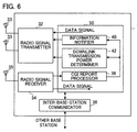
- FIG. 6 is a block diagram illustrating a configuration of a base station 1 according to a first embodiment of the present invention.
- a base station 2 has a configuration similar to the configuration of the base station 1.
- the base station 1 includes a controller 30, a radio signal transmitter 32, transmitting antennae 33, a radio signal receiver 34, a receiving antenna 35, and an inter-base-station communicator 36.
- the radio signal transmitter 32 is a transmitting circuit that converts electrical signals into radio waves transmitted from the transmitting antennae 33 in order for the base station 1 to perform radio transmission to each UE.
- the transmitting antennae 33 constitute an adaptive antenna array.
- the radio signal receiver 34 is a receiving circuit that converts radio waves received from the receiving antenna 35 into electrical signals in order for the base station 1 to perform radio reception from each UE.
- the inter-base-station communicator 36 is a communication interface via which the base station 1 communicates with another base station.
- the controller 30 includes a CQI report processor 38, an information notifier 40, and a downlink transmission power determiner 42.
- the controller 30 is a CPU (central processing unit) that operates in accordance with a computer program.
- the CQI report processor 38, the information notifier 40, and the downlink transmission power determiner 42 are functional blocks that are achieved by the controller 30 functioning in accordance with the computer program.
- the controller 30 processes an uplink data signal that is transmitted from each UE connected to the base station 1 and is received by the radio signal receiver 34.
- the CQI report processor 38 recognizes an SINR at each UE based on a CQI (channel quality indicator) that is reported from each UE connected to the base station 1 and is received by the radio signal receiver 34. Based on the SINR of each UE, the downlink transmission power determiner 42 determines, for NOMA, downlink transmission power that is used for downlink transmission to each UE connected to the base station 1.
- the SINR is a parameter associated with the relative location of the UE within the cell area; specifically, the SINR is a parameter associated with the distance between the UE and the base station.
- the technique for determining downlink transmission power is described above with reference to Formula (1). Note, however, that Formula (1) is a mere example, and the technique for determining downlink transmission power is not limited to Formula (1). The greater the distance between the UE and the base station, the higher downlink transmission power the downlink transmission power determiner 42 allocates to the UE.
- the controller 30 supplies downlink data signals to the radio signal transmitter 32, each of which is directed to a corresponding one of the UEs connected to the base station 1.
- the radio signal transmitter 32 transmits, through the transmitting antennae 33, a radio signal in which non-orthogonal signals (corresponding to the downlink data signals) that are not orthogonal to each other are mixed.
- Each of the non-orthogonal signals is directed to the corresponding one of the UEs connected to the base station 1.
- the radio signal transmitter 32 transmits each of the non-orthogonal signals with the corresponding downlink transmission power determined by the downlink transmission power determiner 42. Accordingly, the data signals are transmitted with different levels of downlink transmission power to the UEs with which the same frequency is simultaneously used for downlink transmission.
- the information notifier 40 notifies each of the UEs connected to the base station 1 of information indicating the location of the UE.
- the "location of the UE” as used herein is the relative location of the UE within the cell area; specifically, the “location of the UE” is a level of distance between the UE and the desired base station.
- the information notifier 40 notifies a UE of information indicating a level of distance between the UE and the desired base station through an upper-layer signal or a control channel signal.
- the information notifier 40 can use, as the information indicating a level of distance between a UE and the desired base station, a predetermined number of bits in a control channel.
- Table 1 shows an example of the information indicating a level of distance between a UE and the desired base station.
- Table 1 shows an example of a case in which the number of UEs to which the same frequency is simultaneously allocated (i.e., the number of UEs that are multiplexed in NOMA) is 4.
- Each of the UEs can recognize the location of that UE with respect to the desired base station by interpreting two bits in a downlink control channel.
- the two-bit value 00 indicates that the UE is the nearest to the boundary of the cell area (cell area boundary), and the two-bit value 11 indicates that the UE is the nearest to the base station.
- the relationship between the bit values and the interpretations is not limited to this example.
- the number of UEs that are multiplexed in NOMA is not limited to 4. There can be different variations in the information indicating a level of distance between a UE and the desired base station. For example, in a case in which the number of UEs that are multiplexed in NOMA is 2, two-bit information as shown in Table 2 or one-bit information as shown in Table 3 may be used.
- Table 2 BIT FIELD INTERPRETATION 00 NEAREST TO CELL AREA BOUNDARY 11 NEAREST TO BASE STATION
- a location recognizer 62 of a UE recognizes a parameter associated with the location of the UE. For example, the relationship between the bit values and the interpretations shown in any of Tables 1 to 3 is provided to the UE in advance. Based on the relationship provided, the location recognizer 62 can recognize the location of the UE from a bit value.
- the information notifier 40 notifies each of the UEs that are connected to the base station 1 of information indicating the number through an upper-layer signal or a control channel signal.
- each of the UEs needs to be notified of information related to downlink transmission power for that UE.
- the information related to downlink transmission power may be information directly indicating the downlink transmission power P k for the UE, or may be information indicating the ratio of the downlink transmission power P k to the total downlink transmission power P.
- the information notifier 40 notifies each UE connected to the base station 1 of such information through an upper-layer signal or a control channel signal.
- FIG. 7 is a block diagram illustrating a configuration of a UE 10 according to the first embodiment.
- the aforementioned UEs (such as UE 100) is configured in a manner similar to the UE 10.
- the UE 10 includes a controller 50, a radio signal transmitter 52, a transmitting antenna 53, a radio signal receiver 54, and multiple receiving antennae 55.
- the radio signal transmitter 52 is a transmitting circuit that converts electrical signals into radio waves transmitted from the transmitting antenna 53 in order for the UE 10 to perform radio transmission to the desired base station.
- the radio signal receiver 54 is a receiving circuit that converts radio waves received from the receiving antennae 55 into electrical signals in order for the UE 10 to perform radio reception from the desired base station.
- the receiving antennae 55 constitute an adaptive antenna array.
- the controller 50 includes a reception quality measurer 60, a CQI reporter 61, a location recognizer 62, a power recognizer 64, an interference rejection combining processor (IRC processor) 66, a demodulator 68, and a non-orthogonal signal canceller 70.
- the controller 50 is a CPU that operates in accordance with a computer program.
- the reception quality measurer 60, the CQI reporter 61, the location recognizer 62, the power recognizer 64, the IRC processor 66, the demodulator 68, and the non-orthogonal signal canceller 70 are functional blocks that are achieved by the controller 50 functioning in accordance with the computer program.
- the controller 50 supplies an uplink data signal to the radio signal transmitter 52, and the radio signal transmitter 52 sends the uplink data signal to the desired base station via the transmitting antenna 53.
- the reception quality measurer 60 measures the SINR of a radio signal received by the radio signal receiver 54.
- the CQI reporter 61 generates a CQI based on the SINR and supplies the CQI to the radio signal transmitter 52.
- the radio signal transmitter 52 transmits the CQI to the desired base station through a control channel.
- the radio signal receiver 54 receives, from the desired base station, a radio signal that includes non-orthogonal signals that are not orthogonal to each other. Additionally, the radio signal receiver 54 receives, from the desired base station, information indicating the location of the UE and information related to downlink transmission power for the UE. Furthermore, in a case in which the desired base station transmits information indicating the number of UEs that are multiplexed in NOMA, the radio signal receiver 54 receives, from the desired base station, the information indicating the number of UEs that are multiplexed in NOMA.
- the location recognizer 62 recognizes, based on the information that indicates the location of the UE and is transmitted from the desired base station, a parameter associated with the location of the UE.
- the power recognizer 64 recognizes the downlink transmission power P k for the UE based on the information that is related to the downlink transmission power for the UE and is transmitted from the desired base station.
- the IRC processor 66 suppresses an interference signal component received from an interfering base station to which the UE is not connected.
- the interference signal component is in a non-orthogonal signal in the radio signal received by the radio signal receiver 54 the radio signal receiver.
- the demodulator 68 demodulates the non-orthogonal signal in which the interference signal component has been suppressed by the IRC processor 66.
- the non-orthogonal signal canceller 70 cancels, from the radio signal, the non-orthogonal signal demodulated by the demodulator 68.
- the IRC processor 66, the demodulator 68, and the non-orthogonal signal canceller 70 operate differently according to the location of the UE within the cell area of the base station, the location being notified by the desired base station and recognized by the location recognizer 62.
- the IRC processor 66 suppresses an interference signal component by IRC-weighting of a received signal received by the radio signal receiver 54.
- the demodulator 68 demodulates the received signal in which the interference signal component has been suppressed by IRC-weighting.
- a signal directed to the UE i.e., a signal with the highest reception power
- the non-orthogonal signal canceller 70 does not operate.
- received signals R 1 (k) received by the radio signal receiver 54 are represented, for example, by Formula (2) below.
- the subscript (k) indicates a downlink resource; specifically, a frequency.
- R 1 k H 1 k P 0 s 0 k + P 1 s 1 k + H 1 Intercell k s 1 Intercell k + I 1 k + N 1 k
- H 1 (k) is a channel impulse matrix for downlink from the desired base station to the UE.
- Formula (2) is used in a case in which the number of UEs that are multiplexed in NOMA is 2 (i.e., in a case in which downlink transmission to two UEs is simultaneously performed using the same frequency).
- P 0 is downlink transmission power for the UE nearer to the desired base station
- P 1 is downlink transmission power for the UE farther from the desired base station (i.e., the UE that performs a demodulation process).
- s 0 (k) is a vector of a transmission data signal directed to the UE nearer to the desired base station
- s 1 (k) is a vector of a transmission data signal directed to the UE farther from the desired base station.
- H 1Intercell (k) is a channel impulse matrix for downlink from an interfering base station that causes dominant interference with the UE to the UE
- s 1Intercell (k) is a vector of a transmission data signal that causes interference with the UE from the interfering base station.
- I 1 (k) is a matrix representing non-dominant interfering components
- N 1 (k) is a matrix representing thermal noise components
- An IRC-weighting matrix W 1(k) for IRC weighting by the IRC processor 66 in a case in which the UE is located farthest away from the desired base station is represented, for example, by Formula (3) below.
- Formula (3) is used in a case in which the number of UEs that are multiplexed in NOMA is 2 (i.e., in a case in which downlink transmission to two UEs is simultaneously performed using the same frequency).
- W 1 k H ⁇ 1 H k P 0 + P 1 H ⁇ 1 k H ⁇ 1 H k + P 1 Intercell H 1 Intercell k H 1 Intercell H k + ⁇ I 1 2 + ⁇ N 1 2 I ⁇ 1
- ⁇ 1 (k) is an estimated channel impulse matrix for downlink from the desired base station to the UE.
- the superscript letter H indicates complex conjugate transpose.
- P 1Intercell is transmission power of an interfering base station that causes dominant interference with the UE, ⁇ I1 2 is non-dominant interference power, and ⁇ N1 2 is thermal noise power.
- I is a unit matrix.
- P 0 +P 1 as used in Formula (3) is the total downlink transmission power P of the desired base station and is known to the UE (the total downlink transmission power P may be a fixed value, or the UE may be notified of the total downlink transmission power P from the desired base station through an upper-layer signal or a reference signal).
- the IRC processor 66 of the UE located farthest away from the desired base station can therefore calculate an IRC-weighting matrix and can multiply a received signal by the IRC-weighting matrix.
- the IRC processor 66 does not need to know the downlink transmission power P 1 for the UE.
- the demodulator 68 of the UE located farthest away from the desired base station can obtain a data signal directed to the UE by simply demodulating the IRC-weighted received signal.
- the IRC processor 66 suppresses an interference signal component by IRC-weighting of a received signal received by the radio signal receiver 54, and the demodulator 68 demodulates the received signal in which the interference signal component has been suppressed by IRC-weighting.
- a signal directed to the UE located farthest away from the desired base station i.e., a signal with the highest reception power is therefore demodulated.
- the non-orthogonal signal canceller 70 then cancels, from the radio signal, the non-orthogonal signal demodulated by the demodulator 68. Then, until the demodulator 68 demodulates a signal directed to its own UE, the IRC processor 66 suppresses an interference signal component in a non-orthogonal signal that is outputted from the non-orthogonal signal canceller 70, and the demodulator 68 demodulates the non-orthogonal signal in which the interference signal component has been suppressed by the IRC processor 66. That is, in this case, until the demodulator 68 demodulates the signal directed to its own UE, the UE repeats interference rejection combining and cancellation of a non-orthogonal signal directed to another UE connected to the desired base station.
- received signals R 0 (k) received by the radio signal receiver 54 are represented, for example, by Formula (4) below.
- R 0 k H 0 k P 0 s 0 k + P 1 s 1 k + H 0 Intercell k s 0 Intercell k + I 0 k + N 0 k
- H 0 (k) is a channel impulse matrix for downlink from the desired base station to the UE.
- Formula (4) is used in a case in which the number of UEs that are multiplexed in NOMA is 2 (i.e., in a case in which downlink transmission to two UEs is simultaneously performed using the same frequency).
- P 0 is downlink transmission power for the UE nearer to the desired base station (i.e., the UE that performs demodulation process)
- P 1 is downlink transmission power for the UE farther from the desired base station (i.e., the other UE).
- H 1I ntercell (k) is a channel impulse matrix for downlink from an interfering base station that causes dominant interference with the UE to the UE
- s 1Intercell (k) is a vector of transmission data signal that causes interference with the UE from the interfering base station.
- I 1 (k) is a matrix representing non-dominant interfering components
- N 1(k) is a matrix representing thermal noise components
- An IRC-weighting matrix W 01(k) for IRC-weighting that the IRC processor 66 performs first i.e., the IRC weighting illustrated in the upper row in FIG. 4
- the IRC weighting illustrated in the upper row in FIG. 4 is represented, for example, by Formula (5) below.
- Formula (5) is used in a case in which the number of UEs that are multiplexed in NOMA is 2 (i.e., in a case in which downlink transmission to two UEs is simultaneously performed using the same frequency).
- W 01 k H ⁇ 0 H k P 0 + P 1 H ⁇ 0 k H ⁇ 0 H k + P 0 Intercell H 0 Intercell k H 0 Intercell H k + ⁇ I 0 2 + ⁇ N 0 2 I ⁇ 1
- ⁇ 0 (k) represents an estimated channel impulse matrix for downlink from the desired base station to the UE.
- P 0Intercell is transmission power of an interfering base station that causes dominant interference with the UE, ⁇ I0 2 is non-dominant interference power, and ⁇ N0 2 is thermal noise power.
- P 0 +P 1 as used in Formula (5) is the total downlink transmission power of the desired base station and is known to the UE. Each of the other parameters is estimated by publicly known techniques.
- the IRC processor 66 of the UE located near the desired base station can therefore calculate an IRC-weighting matrix according to Formula (5) and can multiply a received signal by the IRC-weighting matrix.
- the demodulator 68 of the UE located near the desired base station can obtain a data signal directed to a UE located farthest away from the desired base station by simply demodulating the IRC-weighted received signal.
- the non-orthogonal signal canceller 70 then cancels, from the radio signal, the non-orthogonal signal demodulated by the demodulator 68 (i.e., a replica of the data signal directed to the UE located farthest away from the desired base station).
- the resulting signal R 02 (k) is represented, for example, by Formula (6) below.
- R 02 k H 0 k P 0 s 0 k + H 0 Intercell k s 0 Intercell k + I 0 k + N 0 k
- Formula (6) is used in a case in which the number of UEs that are multiplexed in NOMA is 2 (i.e., in a case in which downlink transmission to two UEs is simultaneously performed using the same frequency).
- P 0 is downlink transmission power for the UE nearer to the desired base station (i.e., the UE that performs a demodulation process).
- the IRC processor 66 suppresses an interference signal component in a non-orthogonal signal that is outputted from the non-orthogonal signal canceller 70 by IRC-weighting.
- An IRC-weighting matrix W 02(k) for IRC-weighting that the IRC processor 66 performs second i.e., the IRC weighting illustrated in the lower row in FIG. 4 ), in a case in which the UE is located within the cell area of the desired base station and is not located nearest to the boundary of the cell area, is represented, for example, by Formula (7) below.
- Formula (7) is used in a case in which the number of UEs that are multiplexed in NOMA is 2 (i.e., in a case in which downlink transmission to two UEs is simultaneously performed using the same frequency).
- W 02 k H ⁇ 0 H k P 0 H ⁇ 0 k H ⁇ 0 H k + P 0 Intercell H 0 Intercell k H 0 Intercell H k + ⁇ I 0 2 + ⁇ N 0 2 I ⁇ 1
- P 0 as used in Formula (7) is downlink transmission power for the UE that performs a demodulation process and is recognized by the power recognizer 64.
- Each of the other parameters is estimated by publicly known techniques.
- the IRC processor 66 of the UE located near the desired base station can therefore calculate an IRC-weighting matrix according to Formula (7) and can multiply the signal R 02 (k) by the IRC-weighting matrix.
- the demodulator 68 of the UE located near the desired base station can obtain a data signal directed to its own UE from the desired base station by demodulating the IRC-weighted signal according to Formula (6).
- Po as used in Formula (6) is downlink transmission power for the UE that performs a demodulation process and is recognized by the power recognizer 64.
- Each of the other parameters is measured or estimated by publicly known techniques.
- the first embodiment achieves non-orthogonal multiple access in which a user device can execute interference rejection combining and appropriately process a radio signal that includes non-orthogonal signals.
- the user device can recognize the location of the user device, and based on the location, the user device can selectively execute interference rejection combining and appropriate processes for demodulation of the non-orthogonal signals.
- a configuration of a base station according to the second embodiment may be similar to that of the base station 1 according to the first embodiment (see FIG. 6 ).
- the information notifier 40 notifies each of the UEs connected to the base station 1 of information indicating the location of that UE and notifies each of the UEs of information related to downlink transmission power for that UE. That is, the information notifier 40 notifies a UE separately of information indicating the location of the UE and information related to downlink transmission power for the UE.
- the information notifier 40 of the base station does not notify each of the UEs connected to the base station 1 of information indicating the location of that UE, but notifies each of the UEs of information related to downlink transmission power for that UE.
- NOMA the greater the distance between a UE and a desired base station, the higher the downlink transmission power.
- a UE can therefore recognize the location of the UE; specifically, the UE can recognize the distance between the UE and the desired base station based on information related to information related to downlink transmission power for the UE.
- the information notifier 40 notifies each of the UEs connected to the base station 1 of information indicating the number using an upper-layer signal or a control channel signal.
- FIG. 8 is a block diagram illustrating a configuration of a UE 10 according to the second embodiment.
- Components of the UE according to the second embodiment may be similar to those of the UE according to the first embodiment (see FIG. 7 ), except that the location recognizer 62 recognizes, based on information that is transmitted from the desired base station and is related to downlink transmission power for the UE, a parameter associated with the location of the UE.
- the power recognizer 64 recognizes the downlink transmission power P k for the UE based on the information that is transmitted from the desired base station and is related to downlink transmission power for the UE.
- the IRC processor 66 of the UE uses the downlink transmission power recognized by the power recognizer 64 for IRC-weighting calculation for demodulating a signal directed to the UE. That is, in a case in which the UE is located within the cell area of the desired base station and is not located nearest to the boundary of the cell area, the IRC processor 66 suppresses an interference signal component on the basis of the downlink transmission power recognized by the power recognizer 64.
- the demodulator 68 of the UE uses the downlink transmission power recognized by the power recognizer 64 to demodulate a signal directed to the UE. That is, in a case in which the UE is located within the cell area of the desired base station and is not located nearest to the boundary of the cell area, the demodulator 68 demodulates the signal directed to the UE on the basis of the downlink transmission power recognized by the power recognizer 64.
- Information related to downlink transmission power of which the information notifier 40 of the base station 1 notifies the UE may be information directly indicating the downlink transmission power P k for the UE, or may be information indicating the ratio of the downlink transmission power P k to the total downlink transmission power P. Since the total downlink transmission power P of the desired base station is known to the UE, the power recognizer 64 of the UE can calculate the downlink transmission power P k for the UE from the information indicating the ratio.
- the information notifier 40 of the base station 1 notifies the UE of information associated with downlink transmission power through an upper-layer signal or a control channel signal.
- the information notifier 40 can use, as the information associated with downlink transmission power, a predetermined number of bits in a control channel.
- Table 4 shows an example of the information associated with downlink transmission power.
- Table 4 shows an example of a case in which the number of UEs to which the same frequency is simultaneously allocated (i.e., the number of UEs that are multiplexed in NOMA) is 4.
- Each of the UEs can recognize the downlink transmission power for the UE (in this example, the ratio of the downlink transmission power P k to the total downlink transmission power P) and the location of the UE with respect to the desired base station by interpreting two bits in a downlink control channel.
- the information associated with downlink transmission power can be considered as information indicating the location of the UE with respect to the desired base station, as well as information associated with downlink transmission power.
- the two-bit value 00 indicates maximum transmission power and that the UE is the nearest to the boundary of the cell area (cell area boundary), and the two-bit value 11 indicates minimum transmission power and that the UE is the nearest to the base station.
- the relationship between the bit values and the interpretations is not limited to this example.
- the number of UEs that are multiplexed in NOMA is not limited to 4. Therefore, there can be different variations in the information associated with downlink transmission power. For example, in a case in which the number of UEs that are multiplexed in NOMA is 2, two-bit information as shown in Table 5 may be used, or one-bit information as shown in Table 6 may be used.
- the location recognizer 62 of the UE Based on such information indicating location and downlink transmission power, the location recognizer 62 of the UE recognizes the location of the UE, and the power recognizer 64 of the UE recognizes the downlink transmission power for the UE.
- the relationship between the bit values and the interpretations shown in any of Tables 4 to 6 may be provided to the UE in advance. Based on this relationship, the location recognizer 62 can recognize the location of the UE from a bit value, and the power recognizer 64 can recognize the downlink transmission power for the UE from the bit value.
- the bits 00 indicate a power ratio of 0.5. Since the downlink transmission power determiner 42 of the base station 1 successively determines downlink transmission power according to, for example, Formula (1), the downlink transmission power determiner 42 may determine that the downlink transmission power for the UE located farthest away from the base station 1 takes on a value other than 0.5. The same applies to the downlink transmission power for other UEs. Therefore, it is preferable that the information notifier 40 of the base station 1 transmits, to UEs, information instructing the UEs to update the interpretations of the downlink transmission power.
- Table 7 shows an example of the information for instructing the UEs to update the interpretations of the downlink transmission power. Such information is notified from the base station 1 to the UEs through an upper-layer signal or a control channel signal. In a UE that has received such information, the power recognizer 64 interprets information indicating downlink transmission power according to the new interpretations and recognizes the downlink transmission power.
- the second embodiment enables a user device to recognize the location of the user device based on information transmitted from a desired base station, and based on the location, the user device selectively execute interference rejection combining and appropriate processes for demodulation of a non-orthogonal signal. Furthermore, the second embodiment allows the user device to perform interference rejection combining and demodulation of a non-orthogonal signal with the use of information that is transmitted from the desired base station and is related to downlink transmission power. Moreover, a single type of information transmitted from the desired base station allows the user device to recognize the location of the user device and the downlink transmission power for the user device. The configuration according to the second embodiment can therefore reduce the amount of traffic compared with the configuration according to the first embodiment.
- the third embodiment is a modification of the second embodiment.
- the information notifier 40 of the base station 1 notifies each UE of, as the information related to the location of the UE and to the downlink transmission power for the UE, information indicating a modulation and coding scheme (MCS) of a downlink data signal for the UE.
- MCS modulation and coding scheme
- the UE In order for a UE to demodulate a downlink data signal, the UE needs to know the MCS of the downlink data signal for the UE. Furthermore, in a case in which the UE is located within the cell area of the desired base station and is not located nearest to the boundary of the cell area (i.e., the power for the UE is lower than that of another UE that is multiplexed in NOMA), the UE needs to know the MCS for the other UE because the UE needs to demodulate a signal directed to the other UE (i.e., a signal with high power).
- the information notifier 40 of the base station 1 notifies a UE of the MCS for the UE and also notifies the UE of the MCS for another UE for which higher power is allocated than the UE.
- MCS-indicating information of which the base station 1 notifies the UE, is associated with the location of the UE related to the MCS and with the downlink transmission power for the UE.
- the term "associated" as used herein means that the UE can interpret the location of the UE and the downlink transmission power for the UE based on the MCS-indicating information transmitted from the base station 1.
- a configuration of a base station according to the third embodiment may be similar to that of the base station 1 according to the first embodiment (see FIG. 6 ).
- a configuration of a UE according to the third embodiment may be similar to that of the UE 10 according to the second embodiment (see FIG. 8 ).
- An MCS of which the information notifier 40 of the base station 1 notifies a UE may be directly associated with the downlink transmission power P k for the UE, or may be associated with the ratio of the downlink transmission power P k to the total downlink transmission power P. Since the total downlink transmission power P of the desired base station is known to the UE, the power recognizer 64 of the UE can calculate the downlink transmission power P k for the UE from the information indicating the ratio. Alternatively, the MCS may be associated with a relative value of downlink transmission power, which is described later, and the UE may calculate the downlink transmission power on the basis of the relative value.
- the location recognizer 62 of the UE recognizes, based on MCS-indicating information transmitted from the desired base station, a parameter associated with the location of the user device.
- the power recognizer 64 recognizes the downlink transmission power P k for the UE based on the MCS-indicating information transmitted from the desired base station.
- the IRC processor 66 of the UE uses the downlink transmission power recognized by the power recognizer 64 to perform IRC-weighting calculation for demodulating a signal directed to the UE. That is, in a case in which the UE is located within the cell area of the desired base station and is not located nearest to the boundary of the cell area, the IRC processor 66 suppresses an interference signal component on the basis of the downlink transmission power recognized by the power recognizer 64.
- the demodulator 68 of the UE uses the downlink transmission power recognized by the power recognizer 64 to demodulate a signal directed to the UE. That is, in a case in which the UE is located within the cell area of the desired base station and is not located nearest to the boundary of the cell area, the demodulator 68 demodulates the signal directed to the UE on the basis of the downlink transmission power recognized by the power recognizer 64.
- the third embodiment can achieve effects similar to those achieved in the second embodiment. Moreover, MCS-indicating information transmitted from a base station allows a user device to recognize the location of the user device and the downlink transmission power for the user device. The amount of traffic can be reduced in the third embodiment compared with the second embodiment.
- Table 8 shows an example of a relationship between MCS-indicating information (MCS indices) and relative values of downlink transmission power.
- MCS Index INTERPRETATION RELATIVE VALUE OF POWER
- the information notifier 40 of the base station 1 notifies multiple UEs that are multiplexed in NOMA of all MCS indices that are used for these UEs.
- the information notifier 40 also notifies each UE about which MCS is for that UE.
- the location recognizer 62 of a UE recognizes relative values of downlink transmission power for the UEs from these MCS indices and recognizes the location of the UE based on these relative values.
- the power recognizer 64 of the UE recognizes the relative values of downlink transmission power for the UEs from these MCS indices and calculates the downlink transmission power for the UE based on these relative values and the known total downlink transmission power P.
- the number of UEs that are multiplexed in NOMA is 2 and that the base station 1 notifies each UE of MCS index 4 and MCS index 22.
- the UE located farthest away from the desired base station i.e., located nearest to the boundary of the cell area
- the UE located nearest to the desired base station is assigned an MCS indicated by the MCS index 22.
- the UE located farthest away from the desired base station is assigned a relative value of power of 5
- the UE located nearest to the desired base station is assigned a relative value of power of 1.
- the total of the relative values is 6.
- the location recognizer 62 of each UE can recognize, based on the number of the MCS indices, the number of the UEs that are multiplexed in NOMA.
- the location recognizer 62 of each UE recognizes the relative values of downlink transmission power for the UEs (5 and 1) from these MCS indices (4 and 22), and recognizes the relative value of downlink transmission power for that UE (5 or 1) from the MCS index for that UE (4 or 22). If the relative value of downlink transmission power for the UE is higher than that of the downlink transmission power for the other UE, the location recognizer 62 recognizes that the UE is located farthest away from the desired base station.
- the location recognizer 62 recognizes that the UE is nearest to the desired base station. Similarly, in a case in which the number of UEs that are multiplexed in NOMA is 3 or more, the location recognizer 62 can recognize the location of the UE (i.e., a level of distance between the UE and the desired base station) on the basis of a comparison between the number of MCS indices that are transmitted from the desired base station and the relative values.
- the power recognizer 64 of each UE can recognize, based on the number of the MCS indices that are transmitted from the desired base station, the number of the UEs that are multiplexed in NOMA.
- the power recognizer 64 of each UE recognizes the relative values of downlink transmission power for the UEs (5 and 1) from these MCS indices (4 and 22), and recognizes the relative value of downlink transmission power for that UE (5 or 1) from the MCS index for that UE (4 or 22).
- the power recognizer 64 calculates the absolute value of downlink transmission power for the UE by multiplying the ratio of the relative value of downlink transmission power for the UE to the total of the relative values by the known total downlink transmission power P.
- the power recognizer 64 can calculate the absolute value of downlink transmission power for the UE on the basis of these relative values.
- the information notifier 40 of the base station 1 transmits, to UEs, information instructing the UEs to update the interpretations of the MCS indices and the relative values of downlink transmission power.
- Table 9 shows an example of the information for instructing the UEs to update the interpretations of the relative values of downlink transmission power. Such information is notified from the base station 1 to the UEs through an upper-layer signal or a control channel signal.
- the fourth embodiment is a modification of the second embodiment.
- the information notifier 40 of the base station 1 uses a reference signal to notify each UE of the information related to the location of that UE and to the downlink transmission power for that UE.
- a configuration of a base station according to the fourth embodiment may be similar to that of the base station 1 according to the first embodiment (see FIG. 6 ).
- a configuration of a UE according to the fourth embodiment may be similar to that of the UE 10 according to the second embodiment (see FIG. 8 ).
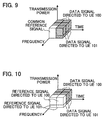
- FIGs. 9 and 10 show that a data signal that is directed to the UE 100 and is having high downlink transmission power and a data signal that is directed to the UE 101 and is having low downlink transmission power are multiplexed and are simultaneously transmitted using the same frequency according to NOMA.
- the base station 1 simultaneously transmits, using the same frequency, a common reference signal with the downlink transmission power for the data signal directed to the UE 100 and with the downlink transmission power for the data signal directed to the UE 101.
- the base station 1 transmits a dedicated reference signal directed to the UE 100 using the downlink transmission power for the data signal for the UE 100 and transmits a dedicated reference signal directed to the UE 101 using the downlink transmission power for the data signal for the UE 101.
- the reference signal directed to the UE 100 and the reference signal directed to the UE 101 are therefore orthogonal to each other. This allows the UE 100 to know the location of the UE 100 alone and the downlink transmission power for the UE 100 alone, and allows the UE 101 to know the location of the UE 101 alone and the downlink transmission power for the UE 101 alone.
- a configuration of a UE according to the fifth embodiment may be similar to that of the UE according to the first embodiment (see FIG. 7 ) or that of the UE 10 according to the second embodiment (see FIG. 8 ).
- the IRC processor 66 of each UE is a successive interference canceller (SIC). SICs are disclosed, for example, in the following documents:
- Raphael Visoz et al. "Binary Versus Symbolic Performance Prediction Methods For Iterative MMSE-IC Multiuser MIMO Joint Decoding", in Proc. IEEE SPAWC, June 2009 .
- each base station notifies a neighboring base station of information related to downlink transmission power that the base station uses for downlink transmission.
- Each base station then notifies UEs connected to that base station of other-base-station power information that is received from the neighboring base station and is related to the downlink transmission power used by the neighboring base station for downlink transmission.
- FIG. 11 is a block diagram illustrating a configuration of a base station 1 according to the fifth embodiment.
- Components of the base station 1 according to the fifth embodiment may be similar to those of the base station 1 according to the first embodiment (see FIG. 6 ).
- the base station 1 according to the fifth embodiment operates in a manner similar to the base station according to any of the first to fourth embodiments.
- the downlink transmission power determiner 42 After determining downlink transmission powers for UEs that use this base station as the desired base station, the downlink transmission power determiner 42 notifies a neighboring base station of information indicating these downlink transmission powers via the inter-base-station communicator 36.
- the downlink transmission power determiner 42 may notify the neighboring base station of information indicating only the highest downlink transmission power among from the downlink transmission powers.
- the IRC processor of a user device is a SIC.
- the SIC properly operates, and therefore, the user device can demodulate a desired data signal.
Landscapes
- Engineering & Computer Science (AREA)
- Computer Networks & Wireless Communication (AREA)
- Signal Processing (AREA)
- Mobile Radio Communication Systems (AREA)
Applications Claiming Priority (2)
| Application Number | Priority Date | Filing Date | Title |
|---|---|---|---|
| JP2013169716A JP6207297B2 (ja) | 2013-08-19 | 2013-08-19 | 無線通信システムおよびユーザ装置 |
| PCT/JP2014/069311 WO2015025664A1 (fr) | 2013-08-19 | 2014-07-22 | Système de communication radio et équipement utilisateur |
Publications (3)
| Publication Number | Publication Date |
|---|---|
| EP3038280A1 true EP3038280A1 (fr) | 2016-06-29 |
| EP3038280A4 EP3038280A4 (fr) | 2016-08-03 |
| EP3038280B1 EP3038280B1 (fr) | 2017-11-08 |
Family
ID=52483446
Family Applications (1)
| Application Number | Title | Priority Date | Filing Date |
|---|---|---|---|
| EP14837523.1A Not-in-force EP3038280B1 (fr) | 2013-08-19 | 2014-07-22 | Système de communication radio et équipement utilisateur |
Country Status (4)
| Country | Link |
|---|---|
| US (1) | US9883464B2 (fr) |
| EP (1) | EP3038280B1 (fr) |
| JP (1) | JP6207297B2 (fr) |
| WO (1) | WO2015025664A1 (fr) |
Cited By (4)
| Publication number | Priority date | Publication date | Assignee | Title |
|---|---|---|---|---|
| WO2018010808A1 (fr) * | 2016-07-14 | 2018-01-18 | Huawei Technologies Co., Ltd. | Procédé et appareil pour accès multiple non orthogonal à réseau modulo pour systèmes miso surchargés |
| WO2018010807A1 (fr) * | 2016-07-14 | 2018-01-18 | Huawei Technologies Co., Ltd. | Procédé et appareil de précodage non linéaire basé sur un réseau pour accès multiple non orthogonal |
| WO2021252212A1 (fr) * | 2020-06-09 | 2021-12-16 | Qualcomm Incorporated | Regroupement d'équipement utilisateur sur la base d'une puissance de liaison descendante |
| US11690083B2 (en) | 2020-06-09 | 2023-06-27 | Qualcomm Incorporated | Grouping user equipment based on downlink power |
Families Citing this family (9)
| Publication number | Priority date | Publication date | Assignee | Title |
|---|---|---|---|---|
| US10271287B2 (en) * | 2015-04-13 | 2019-04-23 | Telefonaktiebolaget Lm Ericsson (Publ) | Power control in a wireless network |
| US10103831B2 (en) | 2015-04-29 | 2018-10-16 | Lg Electronics Inc. | Method for transmitting and receiving signal in wireless communication system and apparatus for performing same |
| JP6462891B2 (ja) * | 2015-10-02 | 2019-01-30 | 株式会社Nttドコモ | 無線基地局、ユーザ端末及び無線通信方法 |
| CN108476085B (zh) * | 2015-12-31 | 2021-05-14 | 华为技术有限公司 | 无线通信方法和设备 |
| CN107026805B (zh) * | 2016-01-29 | 2019-09-17 | 清华大学 | 非正交多址接入传输系统的接收方法及装置 |
| EP3439212B1 (fr) * | 2016-05-26 | 2022-04-20 | LG Electronics Inc. | Procédé d'émission ou de réception de signal et appareil associé dans un système de communication sans fil |
| CN108235417B (zh) * | 2016-12-22 | 2021-03-30 | 华为技术有限公司 | 下行传输方法、基站和终端设备 |
| JP7324040B2 (ja) * | 2019-04-24 | 2023-08-09 | キヤノン株式会社 | 通信装置並びにその通信方法、情報処理装置並びにその制御方法、及び、プログラム |
| JP7529045B2 (ja) * | 2020-12-21 | 2024-08-06 | 日本電信電話株式会社 | 無線通信システム、無線通信方法、送信装置、及び受信装置 |
Family Cites Families (3)
| Publication number | Priority date | Publication date | Assignee | Title |
|---|---|---|---|---|
| JP5451680B2 (ja) * | 2011-04-25 | 2014-03-26 | 株式会社Nttドコモ | 移動通信端末 |
| JP5864200B2 (ja) | 2011-05-20 | 2016-02-17 | 株式会社Nttドコモ | 受信装置、送信装置及び無線通信方法 |
| JPWO2016013457A1 (ja) * | 2014-07-22 | 2017-05-25 | 株式会社Nttドコモ | 基地局およびユーザ装置 |
-
2013
- 2013-08-19 JP JP2013169716A patent/JP6207297B2/ja not_active Expired - Fee Related
-
2014
- 2014-07-22 WO PCT/JP2014/069311 patent/WO2015025664A1/fr not_active Ceased
- 2014-07-22 US US14/906,323 patent/US9883464B2/en not_active Expired - Fee Related
- 2014-07-22 EP EP14837523.1A patent/EP3038280B1/fr not_active Not-in-force
Cited By (7)
| Publication number | Priority date | Publication date | Assignee | Title |
|---|---|---|---|---|
| WO2018010808A1 (fr) * | 2016-07-14 | 2018-01-18 | Huawei Technologies Co., Ltd. | Procédé et appareil pour accès multiple non orthogonal à réseau modulo pour systèmes miso surchargés |
| WO2018010807A1 (fr) * | 2016-07-14 | 2018-01-18 | Huawei Technologies Co., Ltd. | Procédé et appareil de précodage non linéaire basé sur un réseau pour accès multiple non orthogonal |
| WO2021252212A1 (fr) * | 2020-06-09 | 2021-12-16 | Qualcomm Incorporated | Regroupement d'équipement utilisateur sur la base d'une puissance de liaison descendante |
| CN115699943A (zh) * | 2020-06-09 | 2023-02-03 | 高通股份有限公司 | 基于下行链路功率对用户设备进行分组 |
| US11627574B2 (en) | 2020-06-09 | 2023-04-11 | Qualcomm Incorporated | Grouping user equipment based on downlink power |
| US11690083B2 (en) | 2020-06-09 | 2023-06-27 | Qualcomm Incorporated | Grouping user equipment based on downlink power |
| CN115699943B (zh) * | 2020-06-09 | 2026-03-20 | 高通股份有限公司 | 基于下行链路功率对用户设备进行分组 |
Also Published As
| Publication number | Publication date |
|---|---|
| JP2015039132A (ja) | 2015-02-26 |
| WO2015025664A1 (fr) | 2015-02-26 |
| EP3038280A4 (fr) | 2016-08-03 |
| JP6207297B2 (ja) | 2017-10-04 |
| EP3038280B1 (fr) | 2017-11-08 |
| US9883464B2 (en) | 2018-01-30 |
| US20160183199A1 (en) | 2016-06-23 |
Similar Documents
| Publication | Publication Date | Title |
|---|---|---|
| EP3038280B1 (fr) | Système de communication radio et équipement utilisateur | |
| US10356727B2 (en) | User equipment and radio base station | |
| US9923649B2 (en) | Interference measurement method, network-side device and terminal device for improving the interference measurement effect and thus the demodulation performance of data and control channels | |
| EP3185445B1 (fr) | Procédé et appareil de réception de données de liaison descendante par l'intermédiaire d'une suppression et d'une annulation de signaux d'interférence dans un système de communication sans fil | |
| JP6151280B2 (ja) | 移動通信端末 | |
| US9991976B2 (en) | Method and apparatus for interference estimation in wireless communication networks | |
| US10193582B2 (en) | Interference cancellation method and base station apparatus therefor | |
| KR20100102512A (ko) | 다중안테나시스템에서 간섭완화를 위한 제어정보를 전송하기 위한 방법 및 장치 | |
| JP6154830B2 (ja) | 移動通信端末 | |
| US9426683B2 (en) | Method and base station for providing an estimate of interference and noise power of an uplink resource block | |
| EP2981012B1 (fr) | Dispositif utilisateur et procédé d'estimation d'informations d'attribution d'utilisateur | |
| WO2015019743A1 (fr) | Équipement utilisateur, station de base, procédé de traitement d'annulation de brouillage séquentielle et procédé de commande d'annulation de brouillage séquentielle | |
| Shojaeifard et al. | Design, modeling, and performance analysis of multi-antenna heterogeneous cellular networks | |
| Balachandran et al. | NICE: A network interference cancellation engine for opportunistic uplink cooperation in wireless networks | |
| US9787446B2 (en) | Method and device for processing resource blocks | |
| KR101670599B1 (ko) | 백홀 시스템에서 시스템 레벨 시뮬레이션 기반 하이브리드 수신기 | |
| Muhammad | NOMA for advanced mobile generations | |
| Balachandran et al. | Uplink performance enhancement in cellular networks via a Generalized Network Interference Cancellation scheme | |
| Jing et al. | A recovery algorithm for the details of the low resolution video sequence | |
| Balachandran et al. | Uplink cooperation in wireless networks with NICE processing |
Legal Events
| Date | Code | Title | Description |
|---|---|---|---|
| PUAI | Public reference made under article 153(3) epc to a published international application that has entered the european phase |
Free format text: ORIGINAL CODE: 0009012 |
|
| 17P | Request for examination filed |
Effective date: 20160223 |
|
| AK | Designated contracting states |
Kind code of ref document: A1 Designated state(s): AL AT BE BG CH CY CZ DE DK EE ES FI FR GB GR HR HU IE IS IT LI LT LU LV MC MK MT NL NO PL PT RO RS SE SI SK SM TR |
|
| AX | Request for extension of the european patent |
Extension state: BA ME |
|
| A4 | Supplementary search report drawn up and despatched |
Effective date: 20160701 |
|
| RIC1 | Information provided on ipc code assigned before grant |
Ipc: H04B 1/7107 20110101ALI20160627BHEP Ipc: H04J 99/00 20090101AFI20160627BHEP Ipc: H04J 11/00 20060101ALI20160627BHEP Ipc: H04W 52/28 20090101ALI20160627BHEP Ipc: H04W 52/24 20090101ALI20160627BHEP |
|
| DAX | Request for extension of the european patent (deleted) | ||
| GRAP | Despatch of communication of intention to grant a patent |
Free format text: ORIGINAL CODE: EPIDOSNIGR1 |
|
| INTG | Intention to grant announced |
Effective date: 20170619 |
|
| GRAS | Grant fee paid |
Free format text: ORIGINAL CODE: EPIDOSNIGR3 |
|
| GRAA | (expected) grant |
Free format text: ORIGINAL CODE: 0009210 |
|
| AK | Designated contracting states |
Kind code of ref document: B1 Designated state(s): AL AT BE BG CH CY CZ DE DK EE ES FI FR GB GR HR HU IE IS IT LI LT LU LV MC MK MT NL NO PL PT RO RS SE SI SK SM TR |
|
| REG | Reference to a national code |
Ref country code: GB Ref legal event code: FG4D |
|
| REG | Reference to a national code |
Ref country code: CH Ref legal event code: EP Ref country code: AT Ref legal event code: REF Ref document number: 945114 Country of ref document: AT Kind code of ref document: T Effective date: 20171115 |
|
| REG | Reference to a national code |
Ref country code: IE Ref legal event code: FG4D |
|
| REG | Reference to a national code |
Ref country code: DE Ref legal event code: R096 Ref document number: 602014017055 Country of ref document: DE |
|
| REG | Reference to a national code |
Ref country code: NL Ref legal event code: MP Effective date: 20171108 |
|
| REG | Reference to a national code |
Ref country code: LT Ref legal event code: MG4D |
|
| REG | Reference to a national code |
Ref country code: AT Ref legal event code: MK05 Ref document number: 945114 Country of ref document: AT Kind code of ref document: T Effective date: 20171108 |
|
| PG25 | Lapsed in a contracting state [announced via postgrant information from national office to epo] |
Ref country code: NL Free format text: LAPSE BECAUSE OF FAILURE TO SUBMIT A TRANSLATION OF THE DESCRIPTION OR TO PAY THE FEE WITHIN THE PRESCRIBED TIME-LIMIT Effective date: 20171108 Ref country code: FI Free format text: LAPSE BECAUSE OF FAILURE TO SUBMIT A TRANSLATION OF THE DESCRIPTION OR TO PAY THE FEE WITHIN THE PRESCRIBED TIME-LIMIT Effective date: 20171108 Ref country code: NO Free format text: LAPSE BECAUSE OF FAILURE TO SUBMIT A TRANSLATION OF THE DESCRIPTION OR TO PAY THE FEE WITHIN THE PRESCRIBED TIME-LIMIT Effective date: 20180208 Ref country code: LT Free format text: LAPSE BECAUSE OF FAILURE TO SUBMIT A TRANSLATION OF THE DESCRIPTION OR TO PAY THE FEE WITHIN THE PRESCRIBED TIME-LIMIT Effective date: 20171108 Ref country code: SE Free format text: LAPSE BECAUSE OF FAILURE TO SUBMIT A TRANSLATION OF THE DESCRIPTION OR TO PAY THE FEE WITHIN THE PRESCRIBED TIME-LIMIT Effective date: 20171108 Ref country code: ES Free format text: LAPSE BECAUSE OF FAILURE TO SUBMIT A TRANSLATION OF THE DESCRIPTION OR TO PAY THE FEE WITHIN THE PRESCRIBED TIME-LIMIT Effective date: 20171108 |
|
| PG25 | Lapsed in a contracting state [announced via postgrant information from national office to epo] |
Ref country code: IS Free format text: LAPSE BECAUSE OF FAILURE TO SUBMIT A TRANSLATION OF THE DESCRIPTION OR TO PAY THE FEE WITHIN THE PRESCRIBED TIME-LIMIT Effective date: 20180308 Ref country code: AT Free format text: LAPSE BECAUSE OF FAILURE TO SUBMIT A TRANSLATION OF THE DESCRIPTION OR TO PAY THE FEE WITHIN THE PRESCRIBED TIME-LIMIT Effective date: 20171108 Ref country code: HR Free format text: LAPSE BECAUSE OF FAILURE TO SUBMIT A TRANSLATION OF THE DESCRIPTION OR TO PAY THE FEE WITHIN THE PRESCRIBED TIME-LIMIT Effective date: 20171108 Ref country code: LV Free format text: LAPSE BECAUSE OF FAILURE TO SUBMIT A TRANSLATION OF THE DESCRIPTION OR TO PAY THE FEE WITHIN THE PRESCRIBED TIME-LIMIT Effective date: 20171108 Ref country code: BG Free format text: LAPSE BECAUSE OF FAILURE TO SUBMIT A TRANSLATION OF THE DESCRIPTION OR TO PAY THE FEE WITHIN THE PRESCRIBED TIME-LIMIT Effective date: 20180208 Ref country code: GR Free format text: LAPSE BECAUSE OF FAILURE TO SUBMIT A TRANSLATION OF THE DESCRIPTION OR TO PAY THE FEE WITHIN THE PRESCRIBED TIME-LIMIT Effective date: 20180209 Ref country code: RS Free format text: LAPSE BECAUSE OF FAILURE TO SUBMIT A TRANSLATION OF THE DESCRIPTION OR TO PAY THE FEE WITHIN THE PRESCRIBED TIME-LIMIT Effective date: 20171108 |
|
| PG25 | Lapsed in a contracting state [announced via postgrant information from national office to epo] |
Ref country code: CZ Free format text: LAPSE BECAUSE OF FAILURE TO SUBMIT A TRANSLATION OF THE DESCRIPTION OR TO PAY THE FEE WITHIN THE PRESCRIBED TIME-LIMIT Effective date: 20171108 Ref country code: CY Free format text: LAPSE BECAUSE OF FAILURE TO SUBMIT A TRANSLATION OF THE DESCRIPTION OR TO PAY THE FEE WITHIN THE PRESCRIBED TIME-LIMIT Effective date: 20171108 Ref country code: DK Free format text: LAPSE BECAUSE OF FAILURE TO SUBMIT A TRANSLATION OF THE DESCRIPTION OR TO PAY THE FEE WITHIN THE PRESCRIBED TIME-LIMIT Effective date: 20171108 Ref country code: EE Free format text: LAPSE BECAUSE OF FAILURE TO SUBMIT A TRANSLATION OF THE DESCRIPTION OR TO PAY THE FEE WITHIN THE PRESCRIBED TIME-LIMIT Effective date: 20171108 Ref country code: SK Free format text: LAPSE BECAUSE OF FAILURE TO SUBMIT A TRANSLATION OF THE DESCRIPTION OR TO PAY THE FEE WITHIN THE PRESCRIBED TIME-LIMIT Effective date: 20171108 |
|
| REG | Reference to a national code |
Ref country code: DE Ref legal event code: R097 Ref document number: 602014017055 Country of ref document: DE |
|
| PG25 | Lapsed in a contracting state [announced via postgrant information from national office to epo] |
Ref country code: RO Free format text: LAPSE BECAUSE OF FAILURE TO SUBMIT A TRANSLATION OF THE DESCRIPTION OR TO PAY THE FEE WITHIN THE PRESCRIBED TIME-LIMIT Effective date: 20171108 Ref country code: IT Free format text: LAPSE BECAUSE OF FAILURE TO SUBMIT A TRANSLATION OF THE DESCRIPTION OR TO PAY THE FEE WITHIN THE PRESCRIBED TIME-LIMIT Effective date: 20171108 Ref country code: SM Free format text: LAPSE BECAUSE OF FAILURE TO SUBMIT A TRANSLATION OF THE DESCRIPTION OR TO PAY THE FEE WITHIN THE PRESCRIBED TIME-LIMIT Effective date: 20171108 Ref country code: PL Free format text: LAPSE BECAUSE OF FAILURE TO SUBMIT A TRANSLATION OF THE DESCRIPTION OR TO PAY THE FEE WITHIN THE PRESCRIBED TIME-LIMIT Effective date: 20171108 |
|
| PLBE | No opposition filed within time limit |
Free format text: ORIGINAL CODE: 0009261 |
|
| STAA | Information on the status of an ep patent application or granted ep patent |
Free format text: STATUS: NO OPPOSITION FILED WITHIN TIME LIMIT |
|
| 26N | No opposition filed |
Effective date: 20180809 |
|
| PGFP | Annual fee paid to national office [announced via postgrant information from national office to epo] |
Ref country code: DE Payment date: 20180727 Year of fee payment: 5 |
|
| PG25 | Lapsed in a contracting state [announced via postgrant information from national office to epo] |
Ref country code: SI Free format text: LAPSE BECAUSE OF FAILURE TO SUBMIT A TRANSLATION OF THE DESCRIPTION OR TO PAY THE FEE WITHIN THE PRESCRIBED TIME-LIMIT Effective date: 20171108 |
|
| REG | Reference to a national code |
Ref country code: CH Ref legal event code: PL |
|
| GBPC | Gb: european patent ceased through non-payment of renewal fee |
Effective date: 20180722 |
|
| PG25 | Lapsed in a contracting state [announced via postgrant information from national office to epo] |
Ref country code: LU Free format text: LAPSE BECAUSE OF NON-PAYMENT OF DUE FEES Effective date: 20180722 Ref country code: MC Free format text: LAPSE BECAUSE OF FAILURE TO SUBMIT A TRANSLATION OF THE DESCRIPTION OR TO PAY THE FEE WITHIN THE PRESCRIBED TIME-LIMIT Effective date: 20171108 |
|
| REG | Reference to a national code |
Ref country code: BE Ref legal event code: MM Effective date: 20180731 |
|
| REG | Reference to a national code |
Ref country code: IE Ref legal event code: MM4A |
|
| PG25 | Lapsed in a contracting state [announced via postgrant information from national office to epo] |
Ref country code: CH Free format text: LAPSE BECAUSE OF NON-PAYMENT OF DUE FEES Effective date: 20180731 Ref country code: FR Free format text: LAPSE BECAUSE OF NON-PAYMENT OF DUE FEES Effective date: 20180731 Ref country code: LI Free format text: LAPSE BECAUSE OF NON-PAYMENT OF DUE FEES Effective date: 20180731 Ref country code: GB Free format text: LAPSE BECAUSE OF NON-PAYMENT OF DUE FEES Effective date: 20180722 Ref country code: IE Free format text: LAPSE BECAUSE OF NON-PAYMENT OF DUE FEES Effective date: 20180722 |
|
| PG25 | Lapsed in a contracting state [announced via postgrant information from national office to epo] |
Ref country code: BE Free format text: LAPSE BECAUSE OF NON-PAYMENT OF DUE FEES Effective date: 20180731 |
|
| PG25 | Lapsed in a contracting state [announced via postgrant information from national office to epo] |
Ref country code: MT Free format text: LAPSE BECAUSE OF NON-PAYMENT OF DUE FEES Effective date: 20180722 |
|
| REG | Reference to a national code |
Ref country code: DE Ref legal event code: R119 Ref document number: 602014017055 Country of ref document: DE |
|
| PG25 | Lapsed in a contracting state [announced via postgrant information from national office to epo] |
Ref country code: TR Free format text: LAPSE BECAUSE OF FAILURE TO SUBMIT A TRANSLATION OF THE DESCRIPTION OR TO PAY THE FEE WITHIN THE PRESCRIBED TIME-LIMIT Effective date: 20171108 |
|
| PG25 | Lapsed in a contracting state [announced via postgrant information from national office to epo] |
Ref country code: DE Free format text: LAPSE BECAUSE OF NON-PAYMENT OF DUE FEES Effective date: 20200201 |
|
| PG25 | Lapsed in a contracting state [announced via postgrant information from national office to epo] |
Ref country code: PT Free format text: LAPSE BECAUSE OF FAILURE TO SUBMIT A TRANSLATION OF THE DESCRIPTION OR TO PAY THE FEE WITHIN THE PRESCRIBED TIME-LIMIT Effective date: 20171108 |
|
| PG25 | Lapsed in a contracting state [announced via postgrant information from national office to epo] |
Ref country code: MK Free format text: LAPSE BECAUSE OF NON-PAYMENT OF DUE FEES Effective date: 20171108 Ref country code: HU Free format text: LAPSE BECAUSE OF FAILURE TO SUBMIT A TRANSLATION OF THE DESCRIPTION OR TO PAY THE FEE WITHIN THE PRESCRIBED TIME-LIMIT; INVALID AB INITIO Effective date: 20140722 |
|
| PG25 | Lapsed in a contracting state [announced via postgrant information from national office to epo] |
Ref country code: AL Free format text: LAPSE BECAUSE OF FAILURE TO SUBMIT A TRANSLATION OF THE DESCRIPTION OR TO PAY THE FEE WITHIN THE PRESCRIBED TIME-LIMIT Effective date: 20171108 |