EP3038432A1 - Induktionsherd - Google Patents
Induktionsherd Download PDFInfo
- Publication number
- EP3038432A1 EP3038432A1 EP14837725.2A EP14837725A EP3038432A1 EP 3038432 A1 EP3038432 A1 EP 3038432A1 EP 14837725 A EP14837725 A EP 14837725A EP 3038432 A1 EP3038432 A1 EP 3038432A1
- Authority
- EP
- European Patent Office
- Prior art keywords
- magnetic shield
- shield plate
- casing
- induction
- opening
- Prior art date
- Legal status (The legal status is an assumption and is not a legal conclusion. Google has not performed a legal analysis and makes no representation as to the accuracy of the status listed.)
- Granted
Links
Images



Classifications
-
- H—ELECTRICITY
- H05—ELECTRIC TECHNIQUES NOT OTHERWISE PROVIDED FOR
- H05B—ELECTRIC HEATING; ELECTRIC LIGHT SOURCES NOT OTHERWISE PROVIDED FOR; CIRCUIT ARRANGEMENTS FOR ELECTRIC LIGHT SOURCES, IN GENERAL
- H05B6/00—Heating by electric, magnetic or electromagnetic fields
- H05B6/02—Induction heating
- H05B6/10—Induction heating apparatus, other than furnaces, for specific applications
- H05B6/12—Cooking devices
- H05B6/1209—Cooking devices induction cooking plates or the like and devices to be used in combination with them
- H05B6/1245—Cooking devices induction cooking plates or the like and devices to be used in combination with them with special coil arrangements
- H05B6/1254—Cooking devices induction cooking plates or the like and devices to be used in combination with them with special coil arrangements using conductive pieces to direct the induced magnetic field
-
- H—ELECTRICITY
- H05—ELECTRIC TECHNIQUES NOT OTHERWISE PROVIDED FOR
- H05B—ELECTRIC HEATING; ELECTRIC LIGHT SOURCES NOT OTHERWISE PROVIDED FOR; CIRCUIT ARRANGEMENTS FOR ELECTRIC LIGHT SOURCES, IN GENERAL
- H05B6/00—Heating by electric, magnetic or electromagnetic fields
- H05B6/02—Induction heating
- H05B6/10—Induction heating apparatus, other than furnaces, for specific applications
- H05B6/12—Cooking devices
- H05B6/1209—Cooking devices induction cooking plates or the like and devices to be used in combination with them
-
- H—ELECTRICITY
- H05—ELECTRIC TECHNIQUES NOT OTHERWISE PROVIDED FOR
- H05B—ELECTRIC HEATING; ELECTRIC LIGHT SOURCES NOT OTHERWISE PROVIDED FOR; CIRCUIT ARRANGEMENTS FOR ELECTRIC LIGHT SOURCES, IN GENERAL
- H05B6/00—Heating by electric, magnetic or electromagnetic fields
- H05B6/02—Induction heating
- H05B6/06—Control, e.g. of temperature, of power
- H05B6/062—Control, e.g. of temperature, of power for cooking plates or the like
-
- H—ELECTRICITY
- H05—ELECTRIC TECHNIQUES NOT OTHERWISE PROVIDED FOR
- H05B—ELECTRIC HEATING; ELECTRIC LIGHT SOURCES NOT OTHERWISE PROVIDED FOR; CIRCUIT ARRANGEMENTS FOR ELECTRIC LIGHT SOURCES, IN GENERAL
- H05B6/00—Heating by electric, magnetic or electromagnetic fields
- H05B6/02—Induction heating
- H05B6/10—Induction heating apparatus, other than furnaces, for specific applications
- H05B6/12—Cooking devices
- H05B6/1209—Cooking devices induction cooking plates or the like and devices to be used in combination with them
- H05B6/1245—Cooking devices induction cooking plates or the like and devices to be used in combination with them with special coil arrangements
- H05B6/1263—Cooking devices induction cooking plates or the like and devices to be used in combination with them with special coil arrangements using coil cooling arrangements
-
- H—ELECTRICITY
- H05—ELECTRIC TECHNIQUES NOT OTHERWISE PROVIDED FOR
- H05B—ELECTRIC HEATING; ELECTRIC LIGHT SOURCES NOT OTHERWISE PROVIDED FOR; CIRCUIT ARRANGEMENTS FOR ELECTRIC LIGHT SOURCES, IN GENERAL
- H05B6/00—Heating by electric, magnetic or electromagnetic fields
- H05B6/02—Induction heating
- H05B6/10—Induction heating apparatus, other than furnaces, for specific applications
- H05B6/12—Cooking devices
- H05B6/1209—Cooking devices induction cooking plates or the like and devices to be used in combination with them
- H05B6/1245—Cooking devices induction cooking plates or the like and devices to be used in combination with them with special coil arrangements
- H05B6/1272—Cooking devices induction cooking plates or the like and devices to be used in combination with them with special coil arrangements with more than one coil or coil segment per heating zone
-
- H—ELECTRICITY
- H05—ELECTRIC TECHNIQUES NOT OTHERWISE PROVIDED FOR
- H05B—ELECTRIC HEATING; ELECTRIC LIGHT SOURCES NOT OTHERWISE PROVIDED FOR; CIRCUIT ARRANGEMENTS FOR ELECTRIC LIGHT SOURCES, IN GENERAL
- H05B6/00—Heating by electric, magnetic or electromagnetic fields
- H05B6/02—Induction heating
- H05B6/36—Coil arrangements
-
- H—ELECTRICITY
- H05—ELECTRIC TECHNIQUES NOT OTHERWISE PROVIDED FOR
- H05B—ELECTRIC HEATING; ELECTRIC LIGHT SOURCES NOT OTHERWISE PROVIDED FOR; CIRCUIT ARRANGEMENTS FOR ELECTRIC LIGHT SOURCES, IN GENERAL
- H05B2206/00—Aspects relating to heating by electric, magnetic, or electromagnetic fields covered by group H05B6/00
- H05B2206/02—Induction heating
- H05B2206/022—Special supports for the induction coils
-
- H—ELECTRICITY
- H05—ELECTRIC TECHNIQUES NOT OTHERWISE PROVIDED FOR
- H05B—ELECTRIC HEATING; ELECTRIC LIGHT SOURCES NOT OTHERWISE PROVIDED FOR; CIRCUIT ARRANGEMENTS FOR ELECTRIC LIGHT SOURCES, IN GENERAL
- H05B2213/00—Aspects relating both to resistive heating and to induction heating, covered by H05B3/00 and H05B6/00
- H05B2213/07—Heating plates with temperature control means
-
- Y—GENERAL TAGGING OF NEW TECHNOLOGICAL DEVELOPMENTS; GENERAL TAGGING OF CROSS-SECTIONAL TECHNOLOGIES SPANNING OVER SEVERAL SECTIONS OF THE IPC; TECHNICAL SUBJECTS COVERED BY FORMER USPC CROSS-REFERENCE ART COLLECTIONS [XRACs] AND DIGESTS
- Y02—TECHNOLOGIES OR APPLICATIONS FOR MITIGATION OR ADAPTATION AGAINST CLIMATE CHANGE
- Y02B—CLIMATE CHANGE MITIGATION TECHNOLOGIES RELATED TO BUILDINGS, e.g. HOUSING, HOUSE APPLIANCES OR RELATED END-USER APPLICATIONS
- Y02B40/00—Technologies aiming at improving the efficiency of home appliances, e.g. induction cooking or efficient technologies for refrigerators, freezers or dish washers
Definitions
- the present invention relates to an induction-heating cooker having a heating coil to induction-heat a cooking container and an infrared sensor to detect the temperature of the cooking container.
- an induction-heating cooker described in Patent Document 1 is known as the induction-heating cooker having the heating coil to induction-heat the cooking container and the infrared sensor to detect the temperature of the cooking container.
- Fig. 14 is a cross-sectional view of a schematic configuration of the induction-heating cooker described in Patent Document 1.
- the induction-heating cooker described in Patent Document 1 has a main body case 1 and a top plate 3, disposed above the main body case 1, on which a cooking container 2 is placed. Below the top plate 3, a heating coil 4 is disposed to induction-heat the cooking container 2. A heat insulating material 5 is disposed between the top plate 3 and the heating coil 4. Below the heating coil 4, plural rod-shaped ferromagnetic materials (ferrite) 6 are disposed to collect magnetic flux. Below the ferrite 6, a magnetic shield plate 7 is disposed that is made of metal such as aluminum.
- the heating coil 4 and the ferrite 6 are held to a coil base 8 made from a resin material, thereby making up a heating coil unit 9.
- the heating coil 4 is fixed to the upper surface of the coil base 8 by an adhesive, etc.
- the ferrite 6 is embedded within the coil base 8 or is bonded to the lower surface of the coil base 8.
- the heating coil unit 9 is placed on the magnetic shield plate 7. Namely, the magnetic shield plate 7 holds the heating coil 4 and the ferrite 6 by directly holding the coil base 8.
- the magnetic shield plate 7 is biased upward by a spring 10 disposed on a bottom part 1 a of the main body case 1. This causes the heat insulating material 5 to be kept in contact with the lower surface of the top plate 3.
- An infrared sensor 11 is disposed below the magnetic shield plate 7. Below the infrared sensor 11, a printed wiring board 12 is disposed in which a control circuit is formed. The control circuit of the printed wiring board 12 generates a high-frequency current to be supplied to the heating coil 4. The control circuit of the printed wiring board 12 controls the output of the heating coil 4, based on a signal output from the infrared sensor 11.
- a cylindrical body 13 is disposed so as to penetrate the magnetic shield plate 7 and the heating coil 4.
- This cylindrical body 13 is composed integrally with an upper casing 14 covering the infrared sensor 11.
- the cylindrical body 13 and the upper casing 14 are made from a resin material.
- the infrared sensor 11 is mounted on a printed wiring board 15 in which a peripheral circuit including an amplifying circuit is composed and the printed wiring board 15 is mounted on a lower casing 16.
- the lower casing 16 is made from a resin material or an electrically conductive metal material. With the upper casing 14 and the lower casing 16 fitted into each other, the infrared sensor 11 is contained inside a box composed by the upper casing 14 and the lower casing 16.
- the upper casing 14 is attached to the lower surface of the magnetic shield plate 7 as shown in Fig. 14 .
- the magnetic shield plate 7 has an opening formed through which the upper casing 14 can pass and the upper casing 14, passing through this opening, is attached by screws to the lower surface of the coil base 8 on the magnetic shield plate 7.
- the magnetic field has a reduced effect on the infrared sensor 11 and the printed wiring boards 12 and 15 arranged below with respect to the ferrite 6 and the magnetic shield plate 7.
- Patent Document 1 Japanese Laid-Open Patent Publication No. 2011-90991
- the upper casing 14 made from the resin material has a side wall part 14a extending downward so as to surround the infrared sensor 11.
- the lower casing 16 is attached that is made from the resin material or the electrically conductive metal material. This is for the purpose of protecting the infrared sensor 11 while securing the insulation between the infrared sensor 11 and the magnetic shield plate 7.
- the infrared sensor 11 and the printed wiring board 15 with the infrared sensor 11 mounted thereon are affected by the magnetic field permeating the side wall part 14a of the upper casing 14 (e.g., electromagnetic wave generated from the printed wiring board 12). As a result, the detection accuracy of the infrared sensor 11 can possibly be lowered.
- the infrared sensor 11 and the printed wiring board 15 can possibly be strongly affected by the magnetic field generated by the heating coil 4 and passing through the opening of the magnetic shield plate 7.
- the object of the present invention is to provide an induction-heating cooker that is excellent in assembly efficiency as well as being capable of suppressing lowering of detection accuracy of an infrared sensor due to the effect of electromagnetic field by securing electrical insulation and magnetic shield with respect to the infrared sensor.
- an induction-heating cooker comprising:
- an induction-heating cooker is excellent in assembly efficiency as well as being capable of suppressing lowering of detection accuracy of an infrared sensor due to the effect of electromagnetic field by securing electrical insulation and magnetic shield with respect to the infrared sensor.
- An induction-heating cooker has a main body outer frame, a top plate that is disposed above the main body outer frame and on which a cooking container is placed, a heating coil disposed below the top plate to induction-heat the cooking container and having a coil opening, an insulation plate on which the heating coil is placed and that has an insulation plate opening below the coil opening, a ferrite on which the insulation plate is placed, a metallic magnetic shield plate on which the ferrite is placed and that has a magnetic shield plate opening below the insulation plate opening, an infrared sensor arranged below the magnetic shield plate opening to detect an infrared ray radiated from the cooking container and passing through the coil opening, the insulation plate opening, and the magnetic shield plate opening, a casing having at least a bottom part located below the infrared sensor, a side wall part extended upward from the bottom part so as to surround the infrared sensor, and a casing opening through which the infrared ray can pass and made from an electrically conductive material, and a space
- the induction-heating cooker is excellent in assembly efficiency as well as being capable of suppressing lowering of detection accuracy of the infrared sensor due to the effect of electromagnetic field by securing electrical insulation and magnetic shield with respect to the infrared sensor.
- the magnetic shield plate, the ferrite, the insulation plate, and the heating coil can easily be integrated as one body by sequentially piling up these components. For this reason, the magnetic shield plate, the ferrite, the insulation plate, and the heating coil can be incorporated into the main body outer frame at one time.
- the spacer makes it possible to sufficiently secure the electrical insulation between the upper end of the electrically conductive casing and the metallic magnetic shield plate. Therefore, sufficient electrical insulation is also secured between the infrared sensor inside the casing and the magnetic shield plate.
- the infrared sensor inside the casing is not susceptible to the electromagnetic field and can execute accurate temperature detection.
- the spacer may be a frame-like spacer in contact with the upper end of the side wall part of the casing.
- the spacer may be in contact with such a part of the lower surface of the magnetic shield plate that is located above the casing, except for the magnetic shield plate opening.
- the casing may have a top part facing the bottom part across the infrared sensor.
- the casing opening is formed in the top part, and the spacer is in contact with the top part as the upper end of the casing.
- the magnetic shield plate may have a convex part raised downward from the lower surface of the magnetic shield plate so as to at least partially surround the circumference of the spacer in contact with the lower surface. This convex part of the magnetic shield plate shields the electromagnetic field that penetrates the spacer and intrudes into the casing. This makes it possible to further suppress the effect of the electromagnetic field on the infrared sensor.
- the casing may have a heat-dissipating hole in at least either one of the bottom part and the side wall part.
- This heat-dissipating hole can suppress a temperature rise of the infrared sensor and as a result, the lowering is suppressed of the detection accuracy of the infrared sensor.
- the main body outer frame may have a side wall part and a protruding part protruding from the side wall part toward the center of the inside to support the outer circumferential edge of the lower surface of the magnetic shield plate from below. This makes it unnecessary to separately prepare a support member to support the magnetic shield plate inside the main body outer frame (support member can be omitted).
- Fig. 1 is a cross-sectional view of a schematic configuration of the induction-heating cooker according to a first embodiment of the present invention.
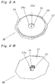
- Fig. 2A is a perspective view of a heating coil unit as viewed from the upper surface side of the heating coil unit of the induction-heating cooker according to the first embodiment of the present invention.
- Fig. 2B is a perspective view of the heating coil unit as viewed from the lower surface side of the heating coil unit of the induction-heating cooker according to the first embodiment of the present invention.
- Fig. 3 is an exploded perspective view of the heating coil unit of the induction-heating cooker according to the first embodiment of the present invention.
- an induction-heating cooker 20 has a box-shape metallic main body outer frame 21 having an opening in its upper part and a crystalized ceramic-made top plate 23 disposed in the upper part of the main body outer frame 21.
- the main body outer frame 21 has a bottom part 21 a and a side wall part 21 b extended upward from the outer edge of the bottom part 21 a.
- a cooking container 22 is placed on the top plate 23.
- a heating coil 24 is disposed to induction-heat the cooking container 22.
- the heating coil 24 has a coil opening 24a as a hole penetrating the heating coil 24.
- the coil opening 24a may be formed at the center of the heating coil 24 as shown in Figs. 1 to 3 or may be disposed between windings of the heating coil 24, though not shown.
- the heating coil 24 is placed on an insulation plate 25 and is bonded to the insulation plate 25 by an adhesive.
- the insulation plate 25 is placed on upper surfaces of plural plate-like ferrites 26 and is bonded to these ferrites 26 by the adhesive. Thus, below the heating coil 24, the plate-like ferrites 26 are disposed, with the insulation plate 25 sandwiched in between.
- the ferrite 26 is a ferromagnetic and has a function of gathering the magnetic flux.
- the plural ferrites 26 are molded in a plate of a substantially cuboid shape and are arranged radially from the vicinity of the center of the heating coil 24 as seen from the above.
- the insulation plate 25 is, for example, laminated mica formed in plate shape by laminating the mica.
- the ferrite 26 may be, for example, a sheet of disc-like ferrite (which, however, must have a ferrite opening arranged below the coil opening so that the infrared ray can pass through it, as will be described later).
- the insulation plate 25 has an insulation plate opening 25a arranged below the coil opening 24a of the heating coil 24.
- the ferrite 26 is placed on the magnetic shield plate 27 and is bonded to the magnetic shield plate 27 by the adhesive. Specifically, plural ferrites 26 are bonded to the upper surface of the magnetic shield plate 27 avoiding a magnetic shield plate opening 27b to be described later.
- the magnetic shield plate 27 is made from an electrically conductive material such as aluminum capable of shielding the magnetic field.
- the magnetic shield plate 27, the ferrite 26, the insulation plate 25, and the heating coil 24, by being sequentially piled up from the bottom and bonded to each other, are integrated as a heating coil unit 28. Rigidity (bending rigidity, deflection rigidity, etc.) of the heating coil unit 28 can be secured by the metallic magnetic shield plate 27.
- the heating coil 24, the insulation plate 25, and the ferrite 26 can be made thin.
- a pressing force of a spring is applied to a heating coil unit to press the heating coil unit against a top plate (to keep the distance between the heating coil unit and the top plate constant), but such a force is not applied to the heating coil unit 28 of this first embodiment. Therefore, the heating coil 24, the insulation plate 25, and the ferrite 26 of this first embodiment do not need the rigidity necessary for resisting the deformation by the pressing force of the spring to press them against the top plate. This makes it possible to achieve lower rigidity, namely, lighter weight and thinner size of these heating coil 24, insulation plate 25, and ferrite 26.
- the magnetic shield plate 27 has a magnetic shield plate opening 27a arranged below the insulation plate opening 25a of the insulation plate 25. With the overlapping of the coil opening 24a of the heating coil 24, the insulation plate opening 25a of the insulation plate 25, and the magnetic shield plate opening 27a of the magnetic shield plate 27, the heating coil unit 28 has an opening running through itself in the vertical direction.
- the heating coil unit 28 is fixed inside the main body outer frame 21.
- An infrared sensor 29 to detect the temperature of the cooking container 22 is mounted on a printed wiring board 29a in which a peripheral circuit is formed.
- the printed wiring board 29a on which the infrared sensor 29 is mounted is housed inside a casing 30. Specifically, the infrared sensor 29 detects the infrared ray radiated from the cooking container 22 and passing through the coil opening 24a, the insulation plate opening 25a, the space among the plural ferrites 26, and the magnetic shield plate opening 27a. For this reason, the infrared sensor 29 is arranged below the magnetic shield plate opening 27a.
- the peripheral circuit of the printed wiring board 29a has, for example, an amplifier composed to amplify an output signal of the infrared sensor 29.
- the casing 30 is made from the electrically conductive material such as aluminum capable of shielding the magnetic field.
- the casing 30 has a bottom part 30b located below the infrared sensor 29 (printed wiring board 29a) and a side wall part 30a extended upward from the bottom part 30b so as to surround the infrared sensor 29.
- the casing 30 is of a box shape having a casing opening 30c in its upper part as shown in Fig. 3 .
- the spacer 31 is made from a material having an electrical insulation, for example, rubber or resin.
- the spacer 31 has a main body part 31 a that comes into contact with an upper end of the casing 30 (specifically, the upper end of the side wall part 30a), two tongue-like attachment parts 31 b protruding outward from the main body part 31 a, and a spacer opening 31 c through which the infrared ray can pass to be detected by the infrared sensor 29 housed inside the casing 30.
- the spacer 31 is of a frame state as shown in Fig. 3 .
- the casing 30 housing the infrared sensor 29 is attached to the spacer 31 and the spacer 31 with the casing 30 attached thereto is attached to the magnetic shield plate 27.
- the spacer 31 main body 31 a thereof
- the spacer 31 is interposed between the lower surface of the magnetic shield plate 27 and the upper end of the casing 30, in contact with the lower surface of the magnetic shield plate 27 and the upper end of the casing 30, preventing the magnetic shield plate 27 and the casing 30 from coming into contact with each other.
- Fig. 4 is a partial cross-sectional view of a configuration of an attachment of the spacer 31 to the magnetic shield plate 27 in the induction-heating cooker 20 according to the first embodiment of the present invention.
- Fig. 5 is a partial perspective view of the attachment part 31 b of the spacer 31 of the induction-heating cooker 20 according to the first embodiment of the present invention.
- the magnetic shield plate 27 has two engaging parts 27b formed therein, to be engaged with the two tongue-like attachment parts 31 b.
- Each of the two engaging parts 27b has a first part extending downward from the lower surface of the magnetic shield plate 27 and a second part extending horizontally (direction orthogonal to drawing) from the first part, as shown in Fig. 4 .
- the attachment part 31 b of the spacer 31 is inserted into a space 27ba between the second part of the engaging part 27b and the lower surface of the magnetic shield plate 27.
- the spacer 31 After the insertion of one attachment part 31 b of the spacer 31 into the space 27ba between the second part of one engaging part 27b and the lower surface of the magnetic shield plate 27, by deforming the spacer 31 using elasticity of the spacer 31 made from rubber or resin, the other attachment part 31 b of the spacer 31 gets engaged with the other engaging part 27b of the magnetic shield plate 27. Thus, the spacer 31 is attached to the lower surface of the magnetic shield plate 27.
- the attachment of the spacer 31 to the magnetic shield plate 27 is not limited to the engagement of the two tongue-like attachment parts 31 b with the corresponding engaging parts 27b. Any method is acceptable if the contact between the spacer 31 and the magnetic shield plate 27 can be maintained.
- a printed wiring board 34 is disposed that has a control circuit including an inverter circuit (not shown).
- the heating coil 24, the insulation plate 25, the ferrite 26, and the magnetic shield plate 27, by being piled up, are integrated as the heating coil unit 28. For this reason, these can be installed, in a state of the heating coil unit 28, inside the main body outer frame 21.
- the ferrite 26 is directly fixed to the magnetic shield plate 27, without intervention of other member (e.g., coil base).
- an assembly efficiency of the induction-heating cooker 20 is enhanced and this makes it possible to manufacture the induction-heating cooker 20 inexpensively (as compared with the case of separately installing the heating coil, the magnetic shield plate, etc., inside the main body outer frame or the case of indirectly fixing the ferrite to the magnetic shield plate by way of other member (e.g., coil base).
- other member e.g., coil base
- Such a heating coil unit 28 is made, for example, by executing the bonding, with one of two constituent elements to be bonded to each other being positioned, using an assembly jig, etc., with respect to the other.
- the electrical insulation between the heating coil 24 as a charging part and the ferrite 26 is secured by the insulation plate 25.
- the laminated mica is preferable as a material of the insulation plate 25 since it is excellent in the electrical insulation, has a high heat resistance, and can easily be formed in a thin sheet.
- the material of the insulation plate 25 is not limited to the laminated mica if it has the required electrical insulation and heat resistance.
- the insulation plate 25 may be made, for example, from heat-resistant resin.
- the control circuit on the printed wiring board 34 includes the inverter and generates a high-frequency current to be supplied to the heating coil 24.
- the infrared ray radiated downward from the cooking container 22 heated by the heating coil 24 is transmitted by the top plate 23, passes through the coil opening 24a, the insulation plate opening 25a, the magnetic shield plate opening 27a, the spacer opening 31 c, and the casing opening 30c, and enters the infrared sensor 29.
- the infrared sensor 29 outputs a signal of a size corresponding to the volume of the entering infrared ray. This output signal is amplified by the peripheral circuit on the printed wiring board 29a.
- the peripheral circuit outputs the amplified output signal of the infrared sensor 29 to the control circuit on the printed wiring board 34 arranged below.
- the control circuit controls the output of the heating coil 24, based on the signal output from the infrared sensor 29 by way of the peripheral circuit. This makes it possible to control the temperature of the cooking container 22 with high accuracy.
- the ferrite 26 suppresses an expansion of the magnetic flux below the heating coil 24 by converging the magnetic flux present below the heating coil 24, out of the magnetic flux generated from the heating coil 24. This causes the magnetic flux leakage to be suppressed, focusing the magnetic flux, without waste, on the cooking container 22 as well as suppressing the effect of the magnetic field on other constituent elements (infrared sensor 29).
- the magnetic shield plate 27 made from the electrically conductive material such as aluminum suppresses the magnetic flux generated from the heating coil 24 leaking downward below the magnetic shield plate 27.
- the bottom part 30b and the side wall part 30a of the casing 30 made from the electrically conductive material such as aluminum.
- the infrared sensor 29 is covered by the magnetic shield plate 27 disposed above it.
- the casing 30 is fixed to the magnetic shield plate 27 by way of the thin-sheet spacer 31 having the electrical insulation intervening between the upper end of the side wall part 30a and the lower surface of the magnetic shield plate 27, in contact therewith.
- the distance between the lower surface of the magnetic shield plate 27 and the upper end of the side wall part 30a of the casing 30, namely, the space through which the electromagnetic wave can pass, is small (to make this space small and in the range in which the electrical insulation between these can be secured, the spacer 31 is as much thin as possible). Therefore, the electromagnetic wave generated from the heating coil 24 or the control circuit of the printed wiring board 34 and advancing toward the infrared sensor 29 is efficiently shielded by the casing 30 and the magnetic shield plate 27.
- the electrical insulation between the casing 30 and the magnetic shield plate 27 is secured by the thin-sheet spacer 31 having the electrical insulation intervening between the upper end of the side wall part 30a of the casing 30 and the lower surface of the magnetic shield plate 27, in contact therewith.
- the presence of the spacer 31 makes it possible to suppress a leakage current leaking from the infrared sensor 29 to the main body outer frame 21 by way of the casing 30, the magnetic shield plate 27, and the support member 35.
- the insulation is required between the main body outer frame 21 and the magnetic shield plate 27, since the electrical insulation between the casing 30 and the magnetic shield plate 27 is secured by the spacer 31, a low insulation level is sufficient for the insulation between the main body outer frame 21 and the magnetic shield plate 27.
- the support member 35 is not necessarily required to be made from an insulation material and the support member 35 made from an electrically conductive material can be used to secure the safety.
- the spacer 31 electrically insulating between the casing 30 and the magnetic shield plate 27 the low insulation level is sufficient for the electrical insulation between the infrared sensor 29 and the casing 30 and the electrical insulation between the main body outer frame 21 and the magnetic shield plate 27 and therefore, for example, a reduction in the number of parts and a higher assembly efficiency can be achieved in the induction-heating cooker.
- the induction-heating cooker 20 is excellent in the assembly efficiency as well as being capable of suppressing the lowering of the detection accuracy of the infrared sensor 29 due to the effect of the electromagnetic field by securing the insulation and the magnetic shield for the infrared sensor 29.
- the casing 30 housing the infrared sensor 29 is attached to the lower surface of the magnetic shield plate 27 by way of the spacer 31 instead of passing through a large opening formed in the magnetic shield plate 27 and being attached to a member (e.g., coil base) on the magnetic shield plate 27. For this reason, it becomes unnecessary to form a large opening in the magnetic shield plate 27.
- This enables the magnetic shield plate 27 to shield much of the magnetic flux generated by the heating coil 24 and going downward below the magnetic shield plate 27.
- the effect of the magnetic field on the infrared sensor 29 and the printed wiring board 34 arranged below the magnetic shield plate 27 is suppressed and the lowering of the detection accuracy of the infrared sensor 29 is suppressed.
- Fig. 6 is a cross-sectional view of a schematic configuration of the induction-heating cooker according to this second embodiment of the present invention.
- Fig. 7A is a perspective view of the heating coil unit as viewed from the upper surface side of the heating coil unit of the induction-heating cooker according to this second embodiment of the present invention.
- Fig. 7B is a perspective view of the heating coil unit as viewed from the lower surface side of the heating coil unit of the induction-heating cooker according to this second embodiment of the present invention.
- Fig. 8 is an exploded perspective view of the heating coil unit of the induction-heating cooker according to this second embodiment of the present invention.
- Fig. 9 is an exploded perspective view of an infrared sensor unit of the induction-heating cooker according to this second embodiment of the present invention.
- an induction-heating cooker 120 largely differs from the induction-heating cooker 20 described above in that a casing 130 has a top part facing a bottom part across the infrared sensor 29.
- the casing 130 is composed of a lower side casing 132 and an upper side casing 133 to house the printed wiring board 29a to which the infrared sensor 29 is mounted.
- the lower side casing 132 has a bottom part 132b and a side wall part 132a extended upward from the bottom part 132b so as to surround the infrared sensor 29.
- the lower side casing 132 is of a box shape having an opening in its upper part.
- the upper side casing 133 is of a shape of a lid with which to cover the box-shaped lower side casing 132 and functions as the top part of the casing 130.
- the upper side casing 133 has a casing opening 133a formed that is arranged above the infrared sensor 29 and through which the infrared ray travelling toward the infrared sensor 29 passes.
- the lower side casing 132 and the upper side casing 133 are made from an electrically conductive material such as aluminum capable of shielding the magnetic field.
- the upper side casing 133 is fixed by a screw 137 to the lower side casing 132 with the printed wiring board 29a, on which the infrared sensor 29 is mounted, housed therein.
- the infrared sensor 29 and the printed wiring board 29a are housed inside the casing 130 composed of the lower side casing 132 and the upper side casing 133.
- a heat-dissipating hole 132c is formed in at least either one of the bottom part 132b and the side wall part 132a of the lower side casing 132, as shown in Fig. 9 .
- This heat-dissipating hole 132c suppresses the temperature rise inside the casing 130 and suppresses the lowering of the detection accuracy of the infrared sensor 29.
- the heat-dissipating hole 132c is made to the size of the required minimum limit to secure the insulation and the magnetic shield for the infrared sensor 29.
- a spacer 131 is made from a material having the electrical insulation, for example, rubber or resin.
- the spacer 131 has a thin-sheet main body part 131 a in contact with the top part as the upper end of the casing 130 (i.e., the upper surface of the upper side casing 133), a spacer opening 131 b through which the infrared ray travelling toward the infrared sensor 29 can pass, a cylindrical part 131 c extending upward from the edge of the spacer opening 131 b, a claw-like attachment part 131d disposed in the main body part 131a, and a side wall part 131e protruding downward from the outer circumferential edge of the lower surface of the main body part 131 a for positioning and holding of the casing 130.
- this spacer 131 when attached to the lower surface of a magnetic shield plate 127, is configured to come into contact with such part of the magnetic shield plate 127 that is located above the casing 130, except for a magnetic shield plate opening 127a.
- the spacer 131 (infrared sensor unit 136) is fixed by a screw 138 to the lower surface of the magnetic shield plate 127, with its claw-like attachment part 131d having passed through an engaging hole 127b formed on the magnetic shield plate 127 and with its cylindrical part 131c inserted into the magnetic shield plate opening 127a of the magnetic shield plate 127.
- the spacer 131 (main body part 131 a thereof) intervenes between the lower surface of the magnetic shield plate 127 and the upper end of the casing 130 (upper surface of the upper side casing 133), in contact with the lower surface of the magnetic shield plate 127 and the upper end of the casing 130.
- the casing 130 with the infrared sensor 29 housed therein is attached to the spacer 131.
- the cylindrical part 131 c of the spacer 131 passes through the magnetic shield plate opening 127a of the magnetic shield plate 127 in a heating coil unit 128, passing through the space between plural ferrites 126, and passing through an insulation plate opening 125a of an insulation plate 125, as shown in Fig. 6 , and reaching the space between the windings of a coil 124, as shown in Fig. 8 .
- the attachment of the spacer 131 to the magnetic shield plate 127 is not limited to the engagement of the claw-like attachment part 131d and the engaging hole 127b and the screw 39. Any attaching method is acceptable if the contact between the spacer 131 and the magnetic shield plate 127 and the insulation between the magnetic shield plate 127 and the casing 130 can be maintained.
- the induction-heating cooker 120 is excellent in the assembly efficiency as well as being capable of suppressing the lowering of the detection accuracy of the infrared sensor 29 due to the effect of the electromagnetic field by securing the insulation and the magnetic shield for the infrared sensor 29.
- the printed wiring board 29a with the infrared sensor 29 mounted thereon is covered by the top part of the casing 130 (upper side casing 133), except for the area above the infrared sensor 29. For this reason, the infrared sensor 29 is more protected against the electromagnetic wave than in the first embodiment.
- the electric insulation between the infrared sensor 29 and the magnetic shield plate 127 is secured at a higher level by the electrically insulating spacer 131 (main body part 131 a thereof) intervening between the top part of the casing 130 and the lower surface of the magnetic shield plate 127.
- the casing may be configured so that the upper end of its side wall part is higher than its top part. In such a case as well, the insulation and the magnetic shield for the infrared sensor inside the casing can likewise be secured.
- This third embodiment is an improved mode of the first embodiment described above. Therefore, in this third embodiment, the same constituent element as that of the first embodiment is given the same reference numeral. In the following, description will be made mainly of the constituent elements different from those of the first embodiment.
- Fig. 10 is a schematic cross-sectional view of a configuration of the induction-heating cooker according to the third embodiment of the present invention.
- a magnetic shield plate 227 of an induction-heating cooker 220 has a convex part 227a raised downward from the lower surface of the magnetic shield plate 227 so as to surround the spacer 31 in contact with the lower surface thereof.
- This convex part 227a can shield the electromagnetic wave that passes through the space between the lower surface of the magnetic shield plate 227 and the upper end of the side wall part 30a of the casing 30, namely, penetrates the electrically insulating spacer 31 and enters the casing 30. This makes the effect of the electromagnetic field on the infrared sensor 29 and the peripheral circuit of the printed wiring board 29a smaller than in the first embodiment.
- the induction-heating cooker 220 can further secure the insulation and the magnetic shield for the infrared sensor 29 and further suppress the lowering of the detection accuracy of the infrared sensor 29 due to the effect of the electromagnetic field.
- the convex part 227a of the magnetic shield plate 227 may be formed by deforming the magnetic shield plate 227.
- the convex part 227a may surround the entire circumference of the spacer 31 or may partially surround the circumference.
- This fourth embodiment is an improved mode of the third embodiment described above. Therefore, in this fourth embodiment, the same constituent element as that of the third embodiment is given the same reference numeral. In the following, description will be made mainly of the constituent elements different from those of the third embodiment.
- Fig. 11 is a cross-sectional view of a schematic configuration of the induction-heating cooker according to the fourth embodiment of the present invention.
- a spacer 331 of an induction-heating cooker 320 has a frame-like main body part 331 a intervening between the upper end of the casing 30 (upper end of the side wall part 30a thereof) and the lower surface of the magnetic shield plate 227, a cover part 331 b extending from the main body part 331 a so as to cover the infrared sensor 29 and the printed wiring board 29a housed inside the casing 30, and a casing opening 331 c that is formed in the cover part 331 b and through which the infrared ray travelling toward the infrared sensor 29 passes.
- the spacer 331 is in contact with such part of the lower surface of the magnetic shield plate 227 that is located above the casing 30, except for a magnetic shield plate opening 227b.
- the cover part 331 b of the spacer 331 enhances the level of the electrical insulation between the infrared sensor 29 and the peripheral circuit on the printed wiring board 29a and the magnetic shield plate 227, as compared with the level of the electrical insulation in the third embodiment in which the spacer has no cover part. For this reason, the distance between the lower surface of the magnetic shield plate 227 and the bottom part 30b of the casing 30 (i.e., distance between the magnetic shield plate 227 and the infrared sensor 29) can be made small. Namely, the casing 30 can be made thin (size in vertical direction can be made small).
- the spacer 31 of the induction-heating cooker 20 of the first embodiment may have the same cover part.
- This fifth embodiment is an improved mode of the first embodiment described above. Therefore, in this fifth embodiment, the same constituent element as that of the first embodiment is given the same reference numeral. In the following, description will be made mainly of the constituent elements different from those of the first embodiment.
- Fig. 12 is a cross-sectional view of a schematic configuration of the induction-heating cooker according to the fifth embodiment of the present invention.
- a casing 430 of an induction-heating cooker 420 has a heat-dissipating hole 430c in a side wall part 430a and a bottom part 430b.
- the heat-dissipating hole may be in at least either one of the side wall part 430a and the bottom part 430b of the casing 430.
- the heat-dissipating hole 430 formed in the casing 430 can discharge to the outside the radiation heat radiated from the magnetic shield plate 27 (such a part of the magnetic shield plate 27 that faces the internal space of the casing 430) to the inside of the casing 430. This makes it possible to suppress the temperature rise of the infrared sensor 29 and as a result, suppress the lowering of the detection accuracy of the infrared sensor 29 due to high temperature.
- This sixth embodiment is an improved mode of the first embodiment described above. Therefore, in this sixth embodiment, the same constituent element as that of the first embodiment is given the same reference numeral. In the following, description will be made mainly of the constituent elements different from those of the first embodiment.
- Fig. 13 is a cross-sectional view of a schematic configuration of the induction-heating cooker according to the sixth embodiment of the present invention.
- a main body outer frame 521 of an induction-heating cooker 520 has a protruding part 521c that protrudes from a side wall part 521 b of the main body outer frame 521 toward the center of the inside and supports the outer circumferential edge of the lower surface of the magnetic shield plate 27 from below.
- the protruding part 521 c is of a step shape.
- the protruding part 521 c is not limited to the step shape but may be of a rib shape, etc.
- the plural support members can be omitted that are disposed at the bottom part of the main body outer frame and support the magnetic shield plate from below as shown in the first embodiment.
- productivity of the induction-heating cooker 520 is enhanced (as compared with the case of disposing plural support members at bottom part of main body outer frame).
- the distance between the top plate 23 and the heating-coil unit 28 can be kept constant by way of the main body outer frame 521, without using the spring as in the conventional configuration (configuration shown in Fig. 14 ).
- the first to the sixth embodiments according to the present invention have been described hereinabove.
- the configurations of the first to the sixth embodiments may be practiced by appropriately combining them.
- the present invention is not limited to the embodiments described above.
- the present invention is applicable to any induction-heating cooker that heats a cooking container by use of a heating coil as well as detecting an infrared ray radiated from the cooking container by an infrared sensor to control the temperature of the cooking container such as, for example, suppressing an excessive temperature rise of the cooking container or keeping the temperature of the cooking container constant, based on results of the detection by the infrared sensor.
Landscapes
- Physics & Mathematics (AREA)
- Electromagnetism (AREA)
- Induction Heating Cooking Devices (AREA)
Applications Claiming Priority (2)
| Application Number | Priority Date | Filing Date | Title |
|---|---|---|---|
| JP2013171887 | 2013-08-22 | ||
| PCT/JP2014/004311 WO2015025523A1 (ja) | 2013-08-22 | 2014-08-21 | 誘導加熱調理器 |
Publications (3)
| Publication Number | Publication Date |
|---|---|
| EP3038432A4 EP3038432A4 (de) | 2016-06-29 |
| EP3038432A1 true EP3038432A1 (de) | 2016-06-29 |
| EP3038432B1 EP3038432B1 (de) | 2017-10-04 |
Family
ID=52483317
Family Applications (1)
| Application Number | Title | Priority Date | Filing Date |
|---|---|---|---|
| EP14837725.2A Active EP3038432B1 (de) | 2013-08-22 | 2014-08-21 | Induktionsherd |
Country Status (6)
| Country | Link |
|---|---|
| US (1) | US20160113070A1 (de) |
| EP (1) | EP3038432B1 (de) |
| JP (1) | JP6323691B2 (de) |
| CN (2) | CN112637983B (de) |
| ES (1) | ES2654058T3 (de) |
| WO (1) | WO2015025523A1 (de) |
Cited By (1)
| Publication number | Priority date | Publication date | Assignee | Title |
|---|---|---|---|---|
| US12200847B2 (en) | 2017-12-28 | 2025-01-14 | Jt International Sa | Induction heating assembly for a vapour generating device |
Families Citing this family (13)
| Publication number | Priority date | Publication date | Assignee | Title |
|---|---|---|---|---|
| EP3082380B1 (de) * | 2015-04-16 | 2020-04-08 | LG Electronics Inc. | Kochvorrichtung |
| US20170071034A1 (en) * | 2015-09-09 | 2017-03-09 | Cooktek Induction Systems, Llc | Induction holding, warming, and cooking system having in-unit magnetic control |
| CN108260240B (zh) * | 2016-12-28 | 2021-12-21 | 佛山市顺德区美的电热电器制造有限公司 | 电磁烹饪设备、电磁加热系统及其加热控制方法 |
| EP3641496A4 (de) * | 2017-06-16 | 2020-06-24 | Mitsubishi Electric Corporation | Kochgerät für induktionserhitzung und sensoreinheit |
| EP3441676A1 (de) * | 2017-08-08 | 2019-02-13 | Aktiebolaget Electrolux | Kochfeld mit einem oder mehreren heizleistungsübertragungselementen |
| JP7038812B2 (ja) * | 2018-06-14 | 2022-03-18 | 三菱電機株式会社 | 誘導加熱調理器 |
| JP7229022B2 (ja) * | 2019-01-22 | 2023-02-27 | 三菱電機株式会社 | 誘導加熱調理器 |
| CN109922553A (zh) * | 2019-03-05 | 2019-06-21 | 徐士刚 | 一种电磁电热一体加热系统 |
| JP7302527B2 (ja) * | 2020-05-08 | 2023-07-04 | 三菱電機株式会社 | 誘導加熱調理器 |
| JP7553821B2 (ja) | 2021-05-07 | 2024-09-19 | タイガー魔法瓶株式会社 | 炊飯器 |
| WO2023146285A1 (ko) * | 2022-01-27 | 2023-08-03 | 삼성전자 주식회사 | 무선전력전송을 이용하는 조리장치에서 노이즈를 차폐하는 방법 및 장치 |
| EP4395458B1 (de) * | 2022-12-27 | 2025-08-06 | Arçelik Anonim Sirketi | Induktionsherd |
| CN116053005A (zh) * | 2023-02-27 | 2023-05-02 | 重庆华创智能科技研究院有限公司 | 一种用于无线充电的电能感应器及发射装置 |
Family Cites Families (16)
| Publication number | Priority date | Publication date | Assignee | Title |
|---|---|---|---|---|
| JPS5739910Y2 (de) * | 1978-07-07 | 1982-09-02 | ||
| JP4125646B2 (ja) * | 2003-07-04 | 2008-07-30 | 松下電器産業株式会社 | 誘導加熱装置 |
| JP4356419B2 (ja) * | 2003-10-15 | 2009-11-04 | パナソニック株式会社 | 誘導加熱調理器 |
| JP4016965B2 (ja) * | 2004-04-08 | 2007-12-05 | 松下電器産業株式会社 | 誘導加熱調理器 |
| US8350197B2 (en) * | 2006-02-21 | 2013-01-08 | Panasonic Corporation | Induction heating cooker |
| CN101690392B (zh) * | 2007-06-22 | 2012-11-21 | 松下电器产业株式会社 | 感应加热烹调器 |
| JP5239515B2 (ja) * | 2008-05-28 | 2013-07-17 | パナソニック株式会社 | 誘導加熱調理器 |
| US8853599B2 (en) * | 2008-05-27 | 2014-10-07 | Panasonic Corporation | Induction heating cooking apparatus |
| JP5136210B2 (ja) * | 2008-05-27 | 2013-02-06 | パナソニック株式会社 | 誘導加熱調理器 |
| CN102077685B (zh) * | 2009-03-13 | 2014-03-19 | 松下电器产业株式会社 | 感应加热烹调器及厨房装置 |
| WO2010106769A1 (ja) * | 2009-03-19 | 2010-09-23 | パナソニック株式会社 | 誘導加熱調理器 |
| JP4864129B2 (ja) * | 2009-10-26 | 2012-02-01 | パナソニック株式会社 | 誘導加熱調理器 |
| JP5662736B2 (ja) * | 2010-08-20 | 2015-02-04 | 株式会社ダイヘン | 電磁誘導加熱調理器の加熱コイルユニット |
| ES2394996B1 (es) * | 2011-01-10 | 2014-01-17 | BSH Electrodomésticos España S.A. | Dispositivo de campo de cocción |
| JP5891442B2 (ja) * | 2011-01-17 | 2016-03-23 | パナソニックIpマネジメント株式会社 | 誘導加熱調理器 |
| ES2423381B1 (es) * | 2012-02-10 | 2014-09-12 | Bsh Electrodomésticos España, S.A. | Aparato de cocción por inducción con sensor de infrarrojos |
-
2014
- 2014-08-21 US US14/893,687 patent/US20160113070A1/en not_active Abandoned
- 2014-08-21 JP JP2015532713A patent/JP6323691B2/ja active Active
- 2014-08-21 WO PCT/JP2014/004311 patent/WO2015025523A1/ja not_active Ceased
- 2014-08-21 ES ES14837725.2T patent/ES2654058T3/es active Active
- 2014-08-21 EP EP14837725.2A patent/EP3038432B1/de active Active
- 2014-08-21 CN CN202110017100.5A patent/CN112637983B/zh active Active
- 2014-08-21 CN CN201480029892.6A patent/CN105409326A/zh active Pending
Cited By (1)
| Publication number | Priority date | Publication date | Assignee | Title |
|---|---|---|---|---|
| US12200847B2 (en) | 2017-12-28 | 2025-01-14 | Jt International Sa | Induction heating assembly for a vapour generating device |
Also Published As
| Publication number | Publication date |
|---|---|
| JPWO2015025523A1 (ja) | 2017-03-02 |
| US20160113070A1 (en) | 2016-04-21 |
| JP6323691B2 (ja) | 2018-05-16 |
| CN112637983A (zh) | 2021-04-09 |
| EP3038432A4 (de) | 2016-06-29 |
| WO2015025523A1 (ja) | 2015-02-26 |
| ES2654058T3 (es) | 2018-02-12 |
| EP3038432B1 (de) | 2017-10-04 |
| CN112637983B (zh) | 2022-09-23 |
| CN105409326A (zh) | 2016-03-16 |
Similar Documents
| Publication | Publication Date | Title |
|---|---|---|
| EP3038432B1 (de) | Induktionsherd | |
| EP3041314B1 (de) | Induktionsherd | |
| EP2288231B1 (de) | Induktionsherd | |
| EP2410815B1 (de) | Induktionsherd | |
| JP6366682B2 (ja) | ハウジング、回路装置、駆動装置及び回路装置を製造する方法 | |
| US20150289418A1 (en) | Electrical machine having a shielding plate | |
| CN111009383B (zh) | 无线电能传输模组及其安装方法 | |
| JP4864129B2 (ja) | 誘導加熱調理器 | |
| US10369892B2 (en) | Coil unit of a device for inductive transmission of electrical power | |
| CN112152421B (zh) | 功率转换器、包括电机和功率转换器的装置及车辆 | |
| JP2010170697A (ja) | 誘導加熱調理器 | |
| JP2010170697A5 (de) | ||
| ATE529895T1 (de) | Vorrichtung mit einer abgeschirmten sandwichstruktur zur detektion von wärmestrahlung und verwendung der vorrichtung | |
| JP6131467B2 (ja) | 誘導加熱調理器 | |
| JP2009289522A (ja) | 誘導加熱調理器 | |
| CN219761362U (zh) | 一种线圈盘组件及烹饪设备 | |
| JP4196101B2 (ja) | 誘導加熱調理器 | |
| JPS633428B2 (de) | ||
| JP2013009883A (ja) | 炊飯器 | |
| HK1157119B (en) | Induction heating cooking apparatus |
Legal Events
| Date | Code | Title | Description |
|---|---|---|---|
| PUAI | Public reference made under article 153(3) epc to a published international application that has entered the european phase |
Free format text: ORIGINAL CODE: 0009012 |
|
| 17P | Request for examination filed |
Effective date: 20160322 |
|
| A4 | Supplementary search report drawn up and despatched |
Effective date: 20160518 |
|
| AK | Designated contracting states |
Kind code of ref document: A1 Designated state(s): AL AT BE BG CH CY CZ DE DK EE ES FI FR GB GR HR HU IE IS IT LI LT LU LV MC MK MT NL NO PL PT RO RS SE SI SK SM TR |
|
| AX | Request for extension of the european patent |
Extension state: BA ME |
|
| DAX | Request for extension of the european patent (deleted) | ||
| GRAP | Despatch of communication of intention to grant a patent |
Free format text: ORIGINAL CODE: EPIDOSNIGR1 |
|
| RIC1 | Information provided on ipc code assigned before grant |
Ipc: H05B 6/12 20060101AFI20170222BHEP Ipc: H05B 6/36 20060101ALI20170222BHEP Ipc: H05B 6/06 20060101ALI20170222BHEP |
|
| INTG | Intention to grant announced |
Effective date: 20170315 |
|
| GRAS | Grant fee paid |
Free format text: ORIGINAL CODE: EPIDOSNIGR3 |
|
| GRAA | (expected) grant |
Free format text: ORIGINAL CODE: 0009210 |
|
| AK | Designated contracting states |
Kind code of ref document: B1 Designated state(s): AL AT BE BG CH CY CZ DE DK EE ES FI FR GB GR HR HU IE IS IT LI LT LU LV MC MK MT NL NO PL PT RO RS SE SI SK SM TR |
|
| REG | Reference to a national code |
Ref country code: GB Ref legal event code: FG4D |
|
| REG | Reference to a national code |
Ref country code: CH Ref legal event code: EP |
|
| REG | Reference to a national code |
Ref country code: AT Ref legal event code: REF Ref document number: 935169 Country of ref document: AT Kind code of ref document: T Effective date: 20171015 |
|
| REG | Reference to a national code |
Ref country code: IE Ref legal event code: FG4D |
|
| REG | Reference to a national code |
Ref country code: DE Ref legal event code: R096 Ref document number: 602014015535 Country of ref document: DE |
|
| REG | Reference to a national code |
Ref country code: NL Ref legal event code: MP Effective date: 20171004 |
|
| REG | Reference to a national code |
Ref country code: ES Ref legal event code: FG2A Ref document number: 2654058 Country of ref document: ES Kind code of ref document: T3 Effective date: 20180212 |
|
| REG | Reference to a national code |
Ref country code: LT Ref legal event code: MG4D |
|
| REG | Reference to a national code |
Ref country code: AT Ref legal event code: MK05 Ref document number: 935169 Country of ref document: AT Kind code of ref document: T Effective date: 20171004 |
|
| PG25 | Lapsed in a contracting state [announced via postgrant information from national office to epo] |
Ref country code: NL Free format text: LAPSE BECAUSE OF FAILURE TO SUBMIT A TRANSLATION OF THE DESCRIPTION OR TO PAY THE FEE WITHIN THE PRESCRIBED TIME-LIMIT Effective date: 20171004 |
|
| PG25 | Lapsed in a contracting state [announced via postgrant information from national office to epo] |
Ref country code: FI Free format text: LAPSE BECAUSE OF FAILURE TO SUBMIT A TRANSLATION OF THE DESCRIPTION OR TO PAY THE FEE WITHIN THE PRESCRIBED TIME-LIMIT Effective date: 20171004 Ref country code: SE Free format text: LAPSE BECAUSE OF FAILURE TO SUBMIT A TRANSLATION OF THE DESCRIPTION OR TO PAY THE FEE WITHIN THE PRESCRIBED TIME-LIMIT Effective date: 20171004 Ref country code: LT Free format text: LAPSE BECAUSE OF FAILURE TO SUBMIT A TRANSLATION OF THE DESCRIPTION OR TO PAY THE FEE WITHIN THE PRESCRIBED TIME-LIMIT Effective date: 20171004 Ref country code: NO Free format text: LAPSE BECAUSE OF FAILURE TO SUBMIT A TRANSLATION OF THE DESCRIPTION OR TO PAY THE FEE WITHIN THE PRESCRIBED TIME-LIMIT Effective date: 20180104 |
|
| PG25 | Lapsed in a contracting state [announced via postgrant information from national office to epo] |
Ref country code: LV Free format text: LAPSE BECAUSE OF FAILURE TO SUBMIT A TRANSLATION OF THE DESCRIPTION OR TO PAY THE FEE WITHIN THE PRESCRIBED TIME-LIMIT Effective date: 20171004 Ref country code: GR Free format text: LAPSE BECAUSE OF FAILURE TO SUBMIT A TRANSLATION OF THE DESCRIPTION OR TO PAY THE FEE WITHIN THE PRESCRIBED TIME-LIMIT Effective date: 20180105 Ref country code: BG Free format text: LAPSE BECAUSE OF FAILURE TO SUBMIT A TRANSLATION OF THE DESCRIPTION OR TO PAY THE FEE WITHIN THE PRESCRIBED TIME-LIMIT Effective date: 20180104 Ref country code: IS Free format text: LAPSE BECAUSE OF FAILURE TO SUBMIT A TRANSLATION OF THE DESCRIPTION OR TO PAY THE FEE WITHIN THE PRESCRIBED TIME-LIMIT Effective date: 20180204 Ref country code: RS Free format text: LAPSE BECAUSE OF FAILURE TO SUBMIT A TRANSLATION OF THE DESCRIPTION OR TO PAY THE FEE WITHIN THE PRESCRIBED TIME-LIMIT Effective date: 20171004 Ref country code: AT Free format text: LAPSE BECAUSE OF FAILURE TO SUBMIT A TRANSLATION OF THE DESCRIPTION OR TO PAY THE FEE WITHIN THE PRESCRIBED TIME-LIMIT Effective date: 20171004 Ref country code: HR Free format text: LAPSE BECAUSE OF FAILURE TO SUBMIT A TRANSLATION OF THE DESCRIPTION OR TO PAY THE FEE WITHIN THE PRESCRIBED TIME-LIMIT Effective date: 20171004 |
|
| REG | Reference to a national code |
Ref country code: DE Ref legal event code: R097 Ref document number: 602014015535 Country of ref document: DE |
|
| PG25 | Lapsed in a contracting state [announced via postgrant information from national office to epo] |
Ref country code: DK Free format text: LAPSE BECAUSE OF FAILURE TO SUBMIT A TRANSLATION OF THE DESCRIPTION OR TO PAY THE FEE WITHIN THE PRESCRIBED TIME-LIMIT Effective date: 20171004 Ref country code: CZ Free format text: LAPSE BECAUSE OF FAILURE TO SUBMIT A TRANSLATION OF THE DESCRIPTION OR TO PAY THE FEE WITHIN THE PRESCRIBED TIME-LIMIT Effective date: 20171004 Ref country code: SK Free format text: LAPSE BECAUSE OF FAILURE TO SUBMIT A TRANSLATION OF THE DESCRIPTION OR TO PAY THE FEE WITHIN THE PRESCRIBED TIME-LIMIT Effective date: 20171004 Ref country code: EE Free format text: LAPSE BECAUSE OF FAILURE TO SUBMIT A TRANSLATION OF THE DESCRIPTION OR TO PAY THE FEE WITHIN THE PRESCRIBED TIME-LIMIT Effective date: 20171004 |
|
| PLBE | No opposition filed within time limit |
Free format text: ORIGINAL CODE: 0009261 |
|
| STAA | Information on the status of an ep patent application or granted ep patent |
Free format text: STATUS: NO OPPOSITION FILED WITHIN TIME LIMIT |
|
| REG | Reference to a national code |
Ref country code: FR Ref legal event code: PLFP Year of fee payment: 5 |
|
| PG25 | Lapsed in a contracting state [announced via postgrant information from national office to epo] |
Ref country code: PL Free format text: LAPSE BECAUSE OF FAILURE TO SUBMIT A TRANSLATION OF THE DESCRIPTION OR TO PAY THE FEE WITHIN THE PRESCRIBED TIME-LIMIT Effective date: 20171004 Ref country code: RO Free format text: LAPSE BECAUSE OF FAILURE TO SUBMIT A TRANSLATION OF THE DESCRIPTION OR TO PAY THE FEE WITHIN THE PRESCRIBED TIME-LIMIT Effective date: 20171004 Ref country code: IT Free format text: LAPSE BECAUSE OF FAILURE TO SUBMIT A TRANSLATION OF THE DESCRIPTION OR TO PAY THE FEE WITHIN THE PRESCRIBED TIME-LIMIT Effective date: 20171004 Ref country code: SM Free format text: LAPSE BECAUSE OF FAILURE TO SUBMIT A TRANSLATION OF THE DESCRIPTION OR TO PAY THE FEE WITHIN THE PRESCRIBED TIME-LIMIT Effective date: 20171004 |
|
| 26N | No opposition filed |
Effective date: 20180705 |
|
| PG25 | Lapsed in a contracting state [announced via postgrant information from national office to epo] |
Ref country code: SI Free format text: LAPSE BECAUSE OF FAILURE TO SUBMIT A TRANSLATION OF THE DESCRIPTION OR TO PAY THE FEE WITHIN THE PRESCRIBED TIME-LIMIT Effective date: 20171004 |
|
| PG25 | Lapsed in a contracting state [announced via postgrant information from national office to epo] |
Ref country code: MC Free format text: LAPSE BECAUSE OF FAILURE TO SUBMIT A TRANSLATION OF THE DESCRIPTION OR TO PAY THE FEE WITHIN THE PRESCRIBED TIME-LIMIT Effective date: 20171004 |
|
| REG | Reference to a national code |
Ref country code: CH Ref legal event code: PL |
|
| PG25 | Lapsed in a contracting state [announced via postgrant information from national office to epo] |
Ref country code: LI Free format text: LAPSE BECAUSE OF NON-PAYMENT OF DUE FEES Effective date: 20180831 Ref country code: CH Free format text: LAPSE BECAUSE OF NON-PAYMENT OF DUE FEES Effective date: 20180831 Ref country code: LU Free format text: LAPSE BECAUSE OF NON-PAYMENT OF DUE FEES Effective date: 20180821 |
|
| REG | Reference to a national code |
Ref country code: BE Ref legal event code: MM Effective date: 20180831 |
|
| PG25 | Lapsed in a contracting state [announced via postgrant information from national office to epo] |
Ref country code: BE Free format text: LAPSE BECAUSE OF NON-PAYMENT OF DUE FEES Effective date: 20180831 |
|
| PG25 | Lapsed in a contracting state [announced via postgrant information from national office to epo] |
Ref country code: MT Free format text: LAPSE BECAUSE OF NON-PAYMENT OF DUE FEES Effective date: 20180821 |
|
| PG25 | Lapsed in a contracting state [announced via postgrant information from national office to epo] |
Ref country code: TR Free format text: LAPSE BECAUSE OF FAILURE TO SUBMIT A TRANSLATION OF THE DESCRIPTION OR TO PAY THE FEE WITHIN THE PRESCRIBED TIME-LIMIT Effective date: 20171004 |
|
| PG25 | Lapsed in a contracting state [announced via postgrant information from national office to epo] |
Ref country code: PT Free format text: LAPSE BECAUSE OF FAILURE TO SUBMIT A TRANSLATION OF THE DESCRIPTION OR TO PAY THE FEE WITHIN THE PRESCRIBED TIME-LIMIT Effective date: 20171004 |
|
| PG25 | Lapsed in a contracting state [announced via postgrant information from national office to epo] |
Ref country code: HU Free format text: LAPSE BECAUSE OF FAILURE TO SUBMIT A TRANSLATION OF THE DESCRIPTION OR TO PAY THE FEE WITHIN THE PRESCRIBED TIME-LIMIT; INVALID AB INITIO Effective date: 20140821 Ref country code: MK Free format text: LAPSE BECAUSE OF NON-PAYMENT OF DUE FEES Effective date: 20171004 Ref country code: CY Free format text: LAPSE BECAUSE OF FAILURE TO SUBMIT A TRANSLATION OF THE DESCRIPTION OR TO PAY THE FEE WITHIN THE PRESCRIBED TIME-LIMIT Effective date: 20171004 Ref country code: IE Free format text: LAPSE BECAUSE OF NON-PAYMENT OF DUE FEES Effective date: 20180821 |
|
| PG25 | Lapsed in a contracting state [announced via postgrant information from national office to epo] |
Ref country code: AL Free format text: LAPSE BECAUSE OF FAILURE TO SUBMIT A TRANSLATION OF THE DESCRIPTION OR TO PAY THE FEE WITHIN THE PRESCRIBED TIME-LIMIT Effective date: 20171004 |
|
| PGFP | Annual fee paid to national office [announced via postgrant information from national office to epo] |
Ref country code: GB Payment date: 20230822 Year of fee payment: 10 |
|
| PGFP | Annual fee paid to national office [announced via postgrant information from national office to epo] |
Ref country code: FR Payment date: 20230825 Year of fee payment: 10 |
|
| PGFP | Annual fee paid to national office [announced via postgrant information from national office to epo] |
Ref country code: ES Payment date: 20231027 Year of fee payment: 10 |
|
| GBPC | Gb: european patent ceased through non-payment of renewal fee |
Effective date: 20240821 |
|
| PG25 | Lapsed in a contracting state [announced via postgrant information from national office to epo] |
Ref country code: GB Free format text: LAPSE BECAUSE OF NON-PAYMENT OF DUE FEES Effective date: 20240821 |
|
| PG25 | Lapsed in a contracting state [announced via postgrant information from national office to epo] |
Ref country code: FR Free format text: LAPSE BECAUSE OF NON-PAYMENT OF DUE FEES Effective date: 20240831 |
|
| REG | Reference to a national code |
Ref country code: ES Ref legal event code: FD2A Effective date: 20251001 |
|
| PG25 | Lapsed in a contracting state [announced via postgrant information from national office to epo] |
Ref country code: ES Free format text: LAPSE BECAUSE OF NON-PAYMENT OF DUE FEES Effective date: 20240822 |
|
| PGFP | Annual fee paid to national office [announced via postgrant information from national office to epo] |
Ref country code: DE Payment date: 20250820 Year of fee payment: 12 |