EP3038502B1 - Verfahren zur durchflussregulierung in einer espressomaschine - Google Patents
Verfahren zur durchflussregulierung in einer espressomaschine Download PDFInfo
- Publication number
- EP3038502B1 EP3038502B1 EP14839762.3A EP14839762A EP3038502B1 EP 3038502 B1 EP3038502 B1 EP 3038502B1 EP 14839762 A EP14839762 A EP 14839762A EP 3038502 B1 EP3038502 B1 EP 3038502B1
- Authority
- EP
- European Patent Office
- Prior art keywords
- flow rate
- brew
- espresso
- valve
- water
- Prior art date
- Legal status (The legal status is an assumption and is not a legal conclusion. Google has not performed a legal analysis and makes no representation as to the accuracy of the status listed.)
- Active
Links
Images


Classifications
-
- A—HUMAN NECESSITIES
- A47—FURNITURE; DOMESTIC ARTICLES OR APPLIANCES; COFFEE MILLS; SPICE MILLS; SUCTION CLEANERS IN GENERAL
- A47J—KITCHEN EQUIPMENT; COFFEE MILLS; SPICE MILLS; APPARATUS FOR MAKING BEVERAGES
- A47J31/00—Apparatus for making beverages
- A47J31/24—Coffee-making apparatus in which hot water is passed through the filter under pressure, i.e. in which the coffee grounds are extracted under pressure
- A47J31/34—Coffee-making apparatus in which hot water is passed through the filter under pressure, i.e. in which the coffee grounds are extracted under pressure with hot water under liquid pressure
-
- A—HUMAN NECESSITIES
- A47—FURNITURE; DOMESTIC ARTICLES OR APPLIANCES; COFFEE MILLS; SPICE MILLS; SUCTION CLEANERS IN GENERAL
- A47J—KITCHEN EQUIPMENT; COFFEE MILLS; SPICE MILLS; APPARATUS FOR MAKING BEVERAGES
- A47J31/00—Apparatus for making beverages
- A47J31/002—Apparatus for making beverages following a specific operational sequence, e.g. for improving the taste of the extraction product
-
- A—HUMAN NECESSITIES
- A23—FOODS OR FOODSTUFFS; TREATMENT THEREOF, NOT COVERED BY OTHER CLASSES
- A23F—COFFEE; TEA; THEIR SUBSTITUTES; MANUFACTURE, PREPARATION, OR INFUSION THEREOF
- A23F5/00—Coffee; Coffee substitutes; Preparations thereof
- A23F5/24—Extraction of coffee; Coffee extracts; Making instant coffee
- A23F5/26—Extraction of water soluble constituents
- A23F5/262—Extraction of water soluble constituents the extraction liquid flowing through a stationary bed of solid substances, e.g. in percolation columns
-
- A—HUMAN NECESSITIES
- A47—FURNITURE; DOMESTIC ARTICLES OR APPLIANCES; COFFEE MILLS; SPICE MILLS; SUCTION CLEANERS IN GENERAL
- A47J—KITCHEN EQUIPMENT; COFFEE MILLS; SPICE MILLS; APPARATUS FOR MAKING BEVERAGES
- A47J31/00—Apparatus for making beverages
- A47J31/24—Coffee-making apparatus in which hot water is passed through the filter under pressure, i.e. in which the coffee grounds are extracted under pressure
- A47J31/34—Coffee-making apparatus in which hot water is passed through the filter under pressure, i.e. in which the coffee grounds are extracted under pressure with hot water under liquid pressure
- A47J31/36—Coffee-making apparatus in which hot water is passed through the filter under pressure, i.e. in which the coffee grounds are extracted under pressure with hot water under liquid pressure with mechanical pressure-producing means
-
- A—HUMAN NECESSITIES
- A47—FURNITURE; DOMESTIC ARTICLES OR APPLIANCES; COFFEE MILLS; SPICE MILLS; SUCTION CLEANERS IN GENERAL
- A47J—KITCHEN EQUIPMENT; COFFEE MILLS; SPICE MILLS; APPARATUS FOR MAKING BEVERAGES
- A47J31/00—Apparatus for making beverages
- A47J31/44—Parts or details or accessories of beverage-making apparatus
- A47J31/52—Alarm-clock-controlled mechanisms for coffee- or tea-making apparatus ; Timers for coffee- or tea-making apparatus; Electronic control devices for coffee- or tea-making apparatus
- A47J31/525—Alarm-clock-controlled mechanisms for coffee- or tea-making apparatus ; Timers for coffee- or tea-making apparatus; Electronic control devices for coffee- or tea-making apparatus the electronic control being based on monitoring of specific process parameters
- A47J31/5251—Alarm-clock-controlled mechanisms for coffee- or tea-making apparatus ; Timers for coffee- or tea-making apparatus; Electronic control devices for coffee- or tea-making apparatus the electronic control being based on monitoring of specific process parameters of pressure
-
- A—HUMAN NECESSITIES
- A47—FURNITURE; DOMESTIC ARTICLES OR APPLIANCES; COFFEE MILLS; SPICE MILLS; SUCTION CLEANERS IN GENERAL
- A47J—KITCHEN EQUIPMENT; COFFEE MILLS; SPICE MILLS; APPARATUS FOR MAKING BEVERAGES
- A47J31/00—Apparatus for making beverages
- A47J31/44—Parts or details or accessories of beverage-making apparatus
- A47J31/52—Alarm-clock-controlled mechanisms for coffee- or tea-making apparatus ; Timers for coffee- or tea-making apparatus; Electronic control devices for coffee- or tea-making apparatus
- A47J31/525—Alarm-clock-controlled mechanisms for coffee- or tea-making apparatus ; Timers for coffee- or tea-making apparatus; Electronic control devices for coffee- or tea-making apparatus the electronic control being based on monitoring of specific process parameters
- A47J31/5255—Alarm-clock-controlled mechanisms for coffee- or tea-making apparatus ; Timers for coffee- or tea-making apparatus; Electronic control devices for coffee- or tea-making apparatus the electronic control being based on monitoring of specific process parameters of flow rate
-
- A—HUMAN NECESSITIES
- A47—FURNITURE; DOMESTIC ARTICLES OR APPLIANCES; COFFEE MILLS; SPICE MILLS; SUCTION CLEANERS IN GENERAL
- A47J—KITCHEN EQUIPMENT; COFFEE MILLS; SPICE MILLS; APPARATUS FOR MAKING BEVERAGES
- A47J31/00—Apparatus for making beverages
- A47J31/24—Coffee-making apparatus in which hot water is passed through the filter under pressure, i.e. in which the coffee grounds are extracted under pressure
Definitions
- the present invention relates generally to regulating a flow rate, and more particularly, but not exclusively, to regulating a variable flow rate of pressurized water in a pump driven espresso machine, during an espresso brewing process.
- Coffee is a concentrated coffee beverage brewed by forcing heated pressurized water through ground coffee beans.
- the beverage produced during an espresso brewing process absorbs more of the flavor producing components, such as the oils and various solids found in the beans.
- an espresso brewing process results in a thicker beverage with a creamy texture and a concentrated and complex taste profile.
- the coffee grounds used for espresso may be ground finer than the coffee grounds used for other brewing processes. This results in greater surface area of coffee grounds for which the pressurized water can come into contact with, absorbing more of the flavor producing chemicals from within the grounds.
- the grounds may be tamped to provide a greater stacking efficiency of the grounds, which promotes the water's penetration of the grounds, resulting in still greater flavor extraction.
- espresso may be served in a small portion referred to as a shot, measuring approximately 1 U.S. fluid ounce.
- espresso may also be served in integer multiples of a shot, such as a double shot or a triple shot.
- Espresso is typically prepared using a specialized coffee machine, referred to as an espresso machine. Brewing a shot of espresso may be referred to as pulling a shot of espresso because some espresso machines require a user of the machine, or a barista, to pull a spring loaded lever that is attached to a piston, where pressure created by the piston forces the water through the coffee grounds.
- the construction of espresso machines may vary, the machines are often loosely categorized by the drive mechanism used to produce the required pressure.
- One popular method used to produce the pressure is to employ a motor driven pump. Machines that employ such a pump are often collectively referred to as pump-driven, or simply pump espresso machines.
- Document WO 2012/070002 A1 describes an espresso coffee machine where two ducts 15, 16 are configured to provide water with two different pressures to the downstream boiler and dispensing unit, namely a lower pressure in a starting phase and a higher pressure in a subsequent phase.
- espresso is a popular beverage worldwide.
- espresso may be used as a base for other popular coffee beverages, such as cappuccinos, lattes, macchiatos, and americanos.
- Some preparations of espresso based beverages may use steam to heat and/or froth milk.
- Many espresso machines are able to supply the heat and pressure required to brew espresso.
- some machines may supply the steam that is used in the preparation of various espresso based beverages.
- the flavor profile of an espresso shot is dependent upon many factors associated with the espresso machine, the coffee grounds, and the brewing process used to produce the shot. Such factors include the coarseness of the ground coffee beans, the temperature, pressure, and volume of water forced through the grounds, as well as the time for which the water is in contact with the grounds and the distribution of water over the grounds. Slowly and fully pre-wetting the grounds, prior to forcing the heated pressurized water through the grounds, may greatly increase the quality and complexity of the taste profile of the shot.
- Coffee beans used to make espresso may contain carbon dioxide and other gasses which may affect the taste profile of the espresso shot. Some of these gasses may be acquired by the beans during a roasting process. Whole coffee beans are roasted prior to grinding the beans and brewing espresso and preparing other coffee drinks with the ground beans. The roasting process, which involves heating the beans, is required to produce some of the characteristic flavors associated with coffee. During the roasting process, carbon dioxide may be formed within the cell structure of the coffee beans.
- a system, method, and apparatus for brewing espresso includes at least two phases: a pre-brew phase and an extraction phase.
- a pre-brew phase and an extraction phase.
- the system, method, and apparatus have greater applications that just brewing espresso, and can be applied to the preparation of other substances and/or beverages such as teas, mattes, other coffee based drinks, and the like.
- water is used throughout as an example for a liquid for which to brew with, other precursors may be used within the system, method, and apparatus disclosed herein.
- Other precursors may include any suitable liquid and/or gas.
- coffee beams are herein used as an example brewing medium, however it will be understood that other substances including, but not limited to other ground organic and/or inorganic matter, such as tea leaves and the like, may be used as the brewing medium.
- the grounds may be fully pre-wetted, or slowly exposed to heated pressurized water, resulting in an out-gassing reaction and releasing at least a portion of the undesired gasses from the grounds.
- the espresso brewing process may transition to the extraction phase.
- heated pressurized water may be forced, or extracted, through the pre-wetted and out-gassed grounds, resulting in an espresso shot with a greater and more complex taste profile.
- the pressurized water may be delivered to the coffee grounds during the pre-brew phase at a brew flow rate that is less than the brew flow rate that the heated pressurized water is delivered to the coffee grounds during the extraction phase.
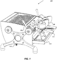
- FIG 1 illustrates a perspective view of one embodiment of a pump-driven espresso machine 100 that regulates at least a brewing flow rate of heated pressurized water during an espresso brewing process, according to the invention.
- espresso machine 100 is shown having steam wand 102, wherein espresso machine 100 may deliver pressurized steam through at least one steam aperture (not shown) disposed on a distal end of steam wand 102.
- at least a portion of the distal end of steam wand 102, including the one or more steam apertures may be submerged in a volume of dairy milk, or other beverage such as soy, rice, or almond milk, wherein the volume of milk may be housed by a steaming cup (not shown).
- Steam delivered to the volume of dairy or non-dairy milk through the one or more steam apertures may produce steamed, frothed, and/or heated milk, used to make an espresso based beverage, such as a latte or cappuccino.
- the position of the steam wand 102 may be rotatably adjustable.
- a flow rate of steam through steam wand 102 and the one or more steam apertures may be controlled by steam handle 104.
- the flow rate of steam through the at least one steam aperture may vary between a maximum flow of steam and no steam.
- the flow rate of steam may depend upon the position of steam handle 104.
- a user of espresso machine 100, or barista may be enabled to rotate the position of steam handle 104 to control the flow rate of steam through steam wand 102 and the at least one steam aperture.
- espresso machine 100 may include brew cap assembly 106.
- the heated pressurized water is delivered to coffee grounds through brew cap assembly 106.
- Brew cap assembly 106 may include at least one giggleur (not shown).
- a giggleur may include at least one of an aperture, orifice, or valve from which pressurized water is forced through and expelled out of.
- a giggleur may be configured and arranged to deliver a volume of water to the coffee grounds in a stream or in a spray, similar to a nozzle assembly.
- Portafilter assembly 110 may be rotatably coupable to an underside of brew cap assembly 106.
- the barista may couple portafilter assembly 110 to the underside of brew cap assembly 106 by at least exerting a rotational force on portafilter handle 112.
- portafilter assembly 110 may house a coffee ground basket (not shown).
- coffee ground basket may be a basket filter that houses coffee grounds.
- brew cap assembly 106 may deliver heated pressurized water, through at least the giggleur (not shown), to coffee grounds housed in the coffee ground basket included in portafilter assembly 110 and coupled to brew cap assembly 106.
- the coffee ground basket may permit the flow of at least a portion of the water delivered by brew cap assembly 106, but restricts the flow of the coffee grounds.
- heated pressurized water may flow from brew cap 106 into portafilter assembly 110 and, due to at least the pressure, at least a portion of the heated pressurized water may be forced or extracted through the coffee grounds housed within coffee ground basket contained within portafilter assembly 110.
- Espresso may be extracted through the basket filter and flow out of portafilter assembly 110 through at least one portafilter aperture (not shown) disposed on an underside of portafilter assembly 110.
- the produced espresso may be deposited in an espresso shot glass (not shown) disposed on drip tray 114.
- espresso machine 100 may include brew pressure gauge 118, which may give an indication, or reading, of the pressure of the heated pressurized water at at least one point in at least one brew flow line (not shown) included in espresso machine 100.
- brew pressure gauge 118 may indicate the pressure within portafilter assembly 110 and between the giggleur and the coffee grounds.
- brew pressure gauge 118 may be an analog gauge.
- brew pressure gauge 118 may be a digital gauge.
- Espresso machine 100 may include water supply 116, which supplies water to espresso machine 100. The water from water supply 116 may be heated and pressurized by espresso machine 100 and used to produce espresso and/or steam.
- water supply 116 may include a water filter.
- espresso machine 100 may include brew handle 108.
- Brew handle 108 may be employed to control an espresso brewing process.
- the espresso brewing process may include at least two phases: a pre-brew phase and an extraction phase.
- the two phases may be distinct and/or independent phases.
- the two phases may be temporally-ordered phases, with the pre-brew phase occurring prior to the extraction phase.
- brew handle 108 may be used to initiate the espresso brewing process. In some of the various embodiments, brew handle 108 may be used to initiate the pre-brew phase of the brewing process. In some of the various embodiments, brew handle 108 may be used to transition the espresso brewing process from the pre-brew phase to the extraction phase. In at least one of the various embodiments, brew handle 108 may be used to terminate the espresso brewing process, including at least terminating the extraction phase.
- brew handle 108 may be employed to control and/or adjust a brew flow rate during the espresso brewing process.
- the brew flow rate may refer to the flow rate of heated pressurized water through espresso machine 100.
- the brew flow rate may refer to the rate that heated pressurized water is being delivered to the coffee grounds by espresso machine 100 and used in the espresso brewing process.
- brew handle 108 may be employed to toggle or transition between at least three brew flow rate settings, including an off setting (or zero-flow setting), a first brew flow rate setting, and a second brew flow rate setting.
- the first brew flow rate setting may be associated with the pre-brew phase.
- the second brew flow rate setting may be associated with the extraction phase.
- the off setting may be associated with a duration phase.
- brew handle 108 may be rotabably transitioned between the at least three settings. In at least one embodiment, the rotated position of brew handle 108 may vary continuously.
- each setting of brew handle 108 may enable a different brew flow rate.
- the off setting, or zero-flow setting, of brew handle 108 may adjust the brew flow rate so that no water is being delivered to the coffee grounds. Accordingly, brew handle 108 may be positioned in the off setting when espresso machine 100 is not currently brewing espresso.
- the brew flow rate may be regulated, adjusted, or otherwise controlled so that espresso machine 100 may deliver a volume of water to the coffee grounds at a brew flow rate equal to a first brew flow rate.
- the brew flow rate when brew handle 108 is positioned in the second brew flow rate setting, the brew flow rate may be regulated, adjusted, or otherwise controlled so that espresso machine 100 may deliver another volume of water to the coffee grounds at a brew flow rate equal to a second brew flow rate.
- the first brew flow rate may be less than or equal to the second brew flow rate.
- the first brew flow rate may be associated with the pre-brew phase of the espresso brewing process.
- the second brew flow rate may be associated with the extraction phase of the espresso brewing process.
- the brew flow rate may be regulated, adjusted, or otherwise controlled by at least employing a brew flow rate regulating assembly (not shown) included in espresso machine 100.
- transitioning brew handle 108 between the settings may vary a pressure within portafilter assembly 110.
- espresso machine 100 may include a processor or processor device (not shown). In some embodiments, the processor device may at least control at least a portion of the espresso brewing process. In some embodiments, the processor device may adjust or control the flow rate during the espresso brewing process. In at least one embodiment, the processor device may control or adjust at least one valve included in espresso machine 100. In some embodiments, espresso machine 100 may include a flow meter (not shown). The flow meter may enable a measurement of the flow rate during the espresso brewing process. The flow meter may enable a measurement of a volume of water flowing during at least a portion of the espresso brewing process.
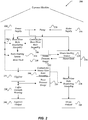
- FIG. 2 illustrates a schematic view of one embodiment of pump-driven espresso machine 200 that includes brew flow rate regulating assembly 236 that may enable regulating a flow rate of water during at least a portion of an espresso brewing process.
- espresso machine 200 may include power supply 222.
- Power supply 222 may provide at least a portion of the electrical power required to operate various components and/or assemblies of espresso machine 200, such as brew heating source 224, steam heating source 228, controls for brew flow rate assembly 208, and pump 226.
- power supply 222 may provide at least electrical power to at least one of brew flow rate regulating assembly 236, steam flow rate regulating assembly 238, and controls for steam flow rate regulating assembly 238.
- dashed directional lines are used to illustrate at least electrical coupling and/or electrical communication of the components.
- the electrical coupling may include the ability to distribute electrical power and/or electrical signals that may enable the controlling or operation of the various components.
- directional solid lines are used to illustrate at least the fluid and/or pressure communication of the components.
- espresso machine 200 may include water supply 216.
- Water supply 216 may supply water to pump 226.
- pump 226 may pump at least a portion of the water supplied by water supply 216 to brew tank 230, wherein the pumped water may be heated, pressurized, and used in the brewing of espresso.
- pump 226 may pump water to steam tank 234, where the pumped water may be used to produce steam used in the preparation of some espresso based drinks.
- water supply 216 may include at least a water filter.
- brew tank 230 and steam tank 234 may be supplied water from separate and/or independent water supplies and/or separate pumps.
- brew tank 230 and steam tank 234 may be supplied water from the same water supply and/or the same pump.
- pump 226 may provide at least a portion of the pressure required to pressurize water stored in brew tank 230.
- a plurality of pumps may be included in espresso machine 200.
- at least one pump may be dedicated to pressurizing water stored in brew tank 230.
- espresso machine 200 may include brew heating source 224.
- Brew heating source 224 may provide at least a portion of the heat energy required to heat water supplied by water supply 216. At least a portion of the water heated by brew heating source 224 may be stored within brew tank 230. In at least one embodiment, brew heating source 224 may be disposed in brew tank 230. In some of the various embodiments, brew heating source 224 may include a resistive element, such as a resistive coil or other type of heating element.
- espresso machine 200 may include steam heating source 228.
- Steam heating source 228 may provide at least a portion of the heat energy required to produce steam within steam tank 234.
- steam heating source 228 may be disposed within steam tank 234.
- steam heating source 228 may include a resistive element, such as a resistive coil or other type of heating element.
- brew tank 230 may store heated and pressurized water. During at least a portion of an espresso brewing process, at least a portion of the heated pressurized water stored within brew tank 230 may flow downstream from brew tank 230 to coffee grounds housed in coffee ground housing 220 and then to espresso output 240. In at least one embodiment, at least a portion of the heated pressurized water may flow through a downstream giggleur 225 before reaching coffee grounds housing 220. In some embodiments, giggleur 225 may include at least an aperture or an orifice. In some embodiments, giggleur 225 may include a nozzle and/or valve.
- a diameter of the aperture or orifice included in giggleur 225 may be with a range, such as 0.5 mm to 1.0 mm. In at least some embodiments, the diameter of the aperture or orifice may be approximately 0.7 mm. In at least one embodiment, giggleur 225 may be characterized by at least a feature size of the included aperture or orifice.
- coffee ground housing 220 may be included in a portafilter assembly, such as portafilter assembly 110 of Figure 1 .
- steam tank 234 may store pressurized steam. In some embodiments, at least a portion of the steam stored within steam tank 234 may flow from steam tank 234 to steam output 202.
- espresso machine 200 may include brew pressure gauge 218.
- Brew pressure gauge 218 may give an indication of pressure at at least one point between pump 226 and coffee ground housing 220.
- brew pressure gauge may give an indication of pressure downstream of giggleur 225 and upstream of coffee grounds.
- espresso machine 200 may include steam pressure gauge 232.
- Steam pressure gauge 232 may give an indication of the pressure at at least one point between pump 226 and steam output 202.
- steam pressure gauge 232 may be an analog gauge.
- steam pressure gauge 232 may be a digital gauge.
- espresso machine 200 may include brew flow rate regulating assembly 236.
- brew flow rate regulating assembly 236 may be upstream of brew tank 236.
- water may flow from pump 226 and through brew flow rate regulating assembly 236 before reaching brew tank 230.
- brew flow rate regulating assembly 236 may be downstream of brew tank 235, but upstream of giggleur 225.
- brew flow rate regulating assembly 236 may regulate, or limit, the flow rate of heated pressurized water arriving at coffee ground housing 220, during at least a portion of the espresso brewing process.
- giggleur 225 may regulate, or limit, the flow rate of heated pressurized water arriving at coffee ground housing 220, during at least a portion of the espresso brewing process.
- the flow rate regulated water may be exposed to coffee grounds housed within.
- at least a portion of the flow regulated water delivered to coffee grounds may pre-wet the coffee grounds.
- At least a portion of the flow regulated water delivered to coffee grounds may be extracted through the pre-wetted coffee grounds to produce espresso.
- at least a portion of the extracted espresso may exit espresso machine 200 through espresso output 240.
- espresso output 240 may include at least a portafilter aperture, such as the portafilter aperture discussed in the context of Figure 1 . The produced espresso may flow from espresso machine 100 via the portafilter aperture.
- brew flow rate regulating assembly 236 may adjustably regulate the flow rate of heated pressurized water flowing to coffee ground housing 220.
- Various embodiments of brew flow rate regulating assembly 236 are described in greater detail with regard to Figures 3-6 .
- brew flow rate regulating assembly 236 may include at least one flow path, wherein a flow rate of water, which flows into and out of brew flow rate regulating assembly 236, may be regulated, adjusted, or otherwise controlled.
- regulating, adjusting, or otherwise controlling the flow rate of water into and out of brew flow rate regulating assembly 236 may regulate, adjust, or otherwise control the brew flow rate of water delivered to the coffee grounds during an espresso brewing process. In at least one embodiment, regulating, adjusting, or otherwise controlling the flow rate of water into and out of brew flow rate regulating assembly 236 may regulate, adjust, or otherwise control the pressure of the water delivered to the coffee grounds during an espresso brewing process.
- brew flow rate regulating assembly 236 may include a plurality of flow paths, where a flow rate of pressurized water, for each individual flow path in the plurality of flow paths, may be regulated, adjusted, or otherwise controlled.
- the plurality of flow paths may include independent flow paths.
- at least a portion of the plurality of flow paths may include parallel flow paths.
- the independent flow paths may vary in both transverse and longitudinal size and/or shape.
- the independent flow paths may vary in transverse diameter or transverse cross-sectional area.
- a flow rate through brew flow rate regulating assembly 236 may include the sum of at least a portion of the individual flow rates of each of the plurality of flow paths.
- brew flow rate regulating assembly 236 may include at least one flow regulating valve. In some embodiments, brew flow rate regulating assembly 236 may include a plurality of flow regulating valves. In at least one embodiment, a flow regulating valve may be an adjustable flow regulating valve. In some embodiments, an adjustable valve may be opened and/or closed. In at least one embodiment, an adjustable valve may include an aperture, wherein the size of the aperture is adjustable. A flow regulating valve may be a needle valve. In some embodiments, a flow regulating valve may be a solenoid valve, such as a two way (2-way) solenoid valve or a three way (3-way) solenoid valve. In some embodiments, a flow regulating valve may be a jet valve.
- the flow rate through at least one of the flow paths may be regulated by the at least one flow regulating valve.
- the flow rate through brew flow rate regulating assembly 236 may be regulated by at least opening and/or closing the at least one flow regulating valve.
- the flow rate through brew flow rate regulating assembly 236 may be regulated by at least adjusting an aperture size for at the least one flow regulating valve.
- controls for brew flow rate regulating assembly 208 may be employed to control, adjust, or limit the flow rate through brew flow rate assembly 236.
- the brew flow rate may be adjusted during the espresso brewing process by manipulating the controls for the brew flow rate regulating assembly 208.
- the controls for the brew flow rate regulating assembly 208 may include a brew handle, such as brew handle 108 of Figure 1 .
- espresso machine 200 may include steam flow rate regulating assembly 238.
- pressurized steam may flow from steam tank 234 and through steam flow rate regulating assembly 238 before being expelled from espresso machine 200 at steam output 202.
- steam flow rate regulating assembly 238 may include a steam valve that controls the steam flowing through steam output 202.
- steam output 202 may include the at least a steam wand, such as steam wand 102 of Figure 1 .
- the steam flow regulating assembly may be controlled by controls for steam flow regulating assembly 204.
- controls for steam flow regulating assembly 204 may include steam handle, such as steam handle 104 shown in Figure 1 .
- controls for steam flow regulating assembly may include electronics that measure and/or control the pressure in the steam tank.
- the espresso brewing process may include a duration phase.
- the duration phase may occur between the pre-brew phase and the extraction phase.
- a duration phase may allow for a more complete out-gassing reaction.
- the brew flow rate may be adjusted to a third brew flow rate during the duration phase.
- the third brew flow rate may be zero during the duration phase of the espresso brewing process.
- the third brew flow rate during the duration phase may be non-zero.
- the third brew flow rate may be less than or equal to the first brew flow rate.
- the third brew flow rate may be greater than the first brew flow rate.
- the brew flow rate of heated pressurized water delivered to the coffee grounds may be regulated during both the pre-brew phase and the extraction phase. In at least one of the various embodiments, the flow rate of water during the pre-brew phase may be less than the flow rate of water during the extraction phase. In at least one of the various embodiments, the flow rate of water during the pre-brew phase and the flow rate of water during the extraction phase may be regulated by employing at least brew flow rate regulation assembly 236 included in espresso machine 200. In at least one of the various embodiments, a user of the espresso machine may adjust the flow rate of water delivered to the coffee grounds by operating controls for brew flow rate assembly 208 included in espresso machine 200.
- a pressure that the water is delivered to the coffee grounds may vary during the espresso brewing process.
- the pressure of the water delivered to the coffee grounds during the pre-brew phase is generally less than the pressure during the extraction phase.
- the generally higher pressure of the water during the extraction phase may force the water through the coffee grounds.
- the lower pressure associated with the pre-brew phase allows the water to pre-wet and/or saturate the grounds SLOWLY, but is not enough pressure to force the water through the grounds to produce properly extracted espresso.
- the pressure of the water delivered to the coffee grounds, during the espresso brewing process may be controlled and/or varied by at least regulating the brew flow rate of water through the espresso machine. In at least one of the various embodiments, the pressure of the water delivered to the coffee grounds, during the espresso brewing process, may be controlled and/or varied by controlling and/or varying a pump included in the espresso machine. In at least one embodiment, the pressure may be a function of time during the espresso brewing process. The exact nature and shape of the function over the course of the brewing process may greatly affect the taste of the brewed espresso.
- the user may control the brewing process, including at least initiating the pre-brew phase, transitioning to the extraction phase, and ending the brew process by operating at least espresso machine controls.
- the user may also control a duration phase, where the brew flow rate is regulated during a duration of time between the pre-brew phase and the extraction phase.
- the brew flow rate may be turned off during the duration phase.
- the espresso machine may include a brew handle. The user may control, adjust, or otherwise vary the brew flow rate throughout the brewing process by manipulating the brew handle.
- the user may control, adjust, or otherwise vary the pressure of the water delivered to the coffee grounds during the espresso brewing process by at least controlling, adjusting, or otherwise varying the brew flow rate.
- the user may be enabled to continuously adjust or vary the brew flow rate during the espresso brewing process.
- the user may be enabled to adjust, vary, or transition the brew flow rate between discrete brew flow rates, such as a first brew flow rate, a second brew flow rate, and the like.
- the user may be enabled to continuously adjust or vary the pressure of water delivered to the coffee grounds during the espresso brewing process.
- FIG 3 illustrates schematically one embodiment of brew flow rate regulation assembly 300, which includes two flow paths.
- brew flow rate regulation assembly 300 may be disposed downstream of pump 226 but upstream of brew tank 230, both of Figure 2 .
- brew flow rate regulation assembly 300 may include brew regulation assembly input 342.
- the pump may pump water into brew flow rate regulation assembly 300 through brew regulation assembly input 342.
- water entering brew flow rate regulation assembly 300 is represented by the arrow shown pointing into brew regulation assembly input 342.
- brew flow rate regulation assembly 300 may include brew regulation assembly output 344.
- the pressurized water that enters brew flow rate regulation assembly 300 through brew regulation assembly input 342, may exit brew flow rate regulation assembly 300 through brew regulation assembly output 344.
- water exiting brew flow rate regulation assembly 300 is represented by the arrow shown pointing out of brew regulation assembly output 344.
- at least a portion of the pressurized water that exits brew flow rate regulation assembly 300 through brew flow rate regulation assembly output 344 may flow to a brew tank, such as brew tank 230 of Figure 2 , after exiting brew flow rate regulation assembly 300.
- At least a portion of the pressurized water that enters the brew tank may flow to the coffee grounds in order to pre-wet the coffee grounds, during at least a portion of an espresso brewing process. At least a portion of the pressurized water that flows to the coffee grounds may be extracted through the coffee grounds to produce espresso, during at least another portion of the espresso brewing process.
- brew flow rate regulation assembly 300 may include a plurality of flow paths, including at least first flow path 350 and second flow path 352. In some embodiments, brew flow rate regulation assembly 300 may include additional flow paths, such as at least a third flow path, such as third flow path 454 of Figure 4 .
- pressurized water may flow through at least one of first flow path 350 and second flow path 352. In some embodiments, during at least a portion of the espresso brewing process, pressurized water may flow simultaneously through both of first flow path 350 and second flow path 352. In some embodiments, during at least a portion of the espresso brewing process, pressurized water may flow through first flow path 350, but not through second flow path 352. In some embodiments, during at least a portion of the espresso brewing process, pressurized water may flow through second flow path 352, but not through first flow path 350.
- first flow path 350 may be defined by at least one of a first transverse cross-sectional area or a first transverse equivalent cross-sectional area.
- a transverse cross-sectional area of first flow path 350 may be uniform.
- the transverse cross-sectional area of first flow path 350 may be non-uniform.
- the first transverse cross-sectional area may be defined by at least one of a first diameter, first radius, or other first linear dimension.
- the first transverse cross-sectional area may be defined by at least two linear dimensions, such as a first width and a first height.
- the flow of pressurized water through first flow path 350 may be limited by the first transverse cross-sectional area.
- water may flow into first flow path 350 through at least brew regulation assembly input 342.
- water that flows through first flow path 350 may flow out of brew flow rate regulation assembly 300 through brew regulation assembly output 344.
- the flow rate of water entering into first flow path 350 may be regulated, or limited, by at least first valve 346.
- first valve 346 may be disposed within first flow path 350 or near an input to first flow path 350.
- first valve 346 may be an adjustable valve. In at least one embodiment, first valve 346 may be a controllable valve, where first valve 346 is at least partially controlled or adjusted by at least controls for brew flow rate regulating assembly 308, where controls for brew flow regulating assembly 308 may include controls for brew flow rate regulating assembly 208 of Figure 2 . In at least one embodiment, controls for brew flow rate regulating assembly 308 may include a brew handle, such as brew handle 108 of Figure 1 . In at least one embodiment, controls for brew flow rate regulating assembly 308 may include an adjustment knob.
- control signal line for first valve 356 may carry a first control signal from controls for brew flow rate regulating assembly 308 to first valve 356.
- the first control signal may adjust, control, or otherwise operate first valve 346.
- the first control signal may be a mechanical signal, electrical signal, optical signal, or the like.
- controlling or operating first valve 346 may include enabling the opening or closing of first valve 346.
- An open first valve 346 may enable water to flow through first flow path 350.
- water flowing into first flow path 350 through first valve 346 is represented by the arrow placed in first flow path 350. When closed, first valve 346 may prohibit, or block, water from flowing through first flow path 350.
- first valve 346 may include at least a first valve aperture (not shown), wherein an aperture size of the first valve aperture may be adjusted to regulate the flow of water through first flow path 350. In some embodiments, the size of the first valve aperture may be adjusted by employing at least controls for brew flow rate regulating assembly 308. In some embodiments, the size of the first valve aperture may be adjusted by employing other controls, such as a rotatable mechanism, such as a knob adjustment, mechanically connected to, or included in, first valve 346. In at least one embodiment, first valve 346 may be a needle valve, wherein the aperture size of the first valve 346 may be adjusted by adjusting the placement of the needle, or plunger. In at least one embodiment, first valve 346 may be a solenoid valve, such as a 2-way solenoid valve or a 3-way solenoid valve. In at least one embodiment, first valve 346 may be a jet valve or a nozzle.
- second flow path 352 may be defined by at least a second transverse cross-sectional area or a second equivalent transverse cross-sectional area.
- a transverse cross-sectional area of second flow path 352 may be uniform.
- the transverse cross-sectional area of second flow path 352 may be non-uniform.
- the second average transverse cross-sectional area may be defined by at least one of a second diameter, second radius, or other second linear dimension.
- the second transverse cross-sectional area may be defined by at least two linear dimensions, such as a second width and a second height.
- the flow of pressurized water through second flow path 352 may be limited by the second transverse cross-sectional area.
- the transverse cross-sectional area of first flow path 350 may be less than or equal to the transverse cross-sectional area of second flow path 352. In at least one embodiment, the transverse cross-sectional area of first flow path 350 may be greater than the transverse cross-sectional area of second flow path 352.
- water may flow into second flow path 352 through at least brew regulation assembly input 342.
- water that flows through second flow path 352 may flow out of brew flow rate regulation assembly 300 through brew regulation assembly output 344.
- water flowing into second flow path 352 may be regulated, or limited, by at least second valve 348.
- second valve 348 may be disposed within second flow path 352 or near an input to second flow path 352.
- second valve 348 may be an adjustable valve.
- second valve 348 may be a controllable valve, where second valve 348 is at least partially controlled or adjusted by at least controls for brew flow rate regulating assembly 308.
- control signal line for second valve 358 may carry a second control signal from controls for brew flow rate regulating assembly 308 to second valve 358.
- the second control signal may adjust, control, or otherwise operate second valve 348.
- the second control signal may be a mechanical signal, electrical signal, optical signal, or the like.
- controlling or operating second valve 348 may include enabling the opening or closing of second valve 348.
- An open second valve 348 may enable water to flow through second flow path 352.
- water flowing into second flow path 352 through second valve 348 is represented by the arrow placed in second flow path 352. When closed, second valve 348 may prohibit water from flowing through second flow path 352.
- second valve 348 may include at least a second valve aperture (not shown), wherein an aperture size of the first valve aperture may be adjusted to regulate the flow of water through second flow path 352.
- the size of the second valve aperture may be adjusted by employing at least controls for brew flow rate regulating assembly.
- the size of the second valve aperture may be adjusted by employing other controls, such as a rotatable mechanism mechanically connected to, or included, in the valve.
- second valve 348 may be a needle valve, wherein the aperture size of second valve 348 may be adjusted by adjusting the placement of the needle.
- second valve 348 may be a solenoid valve, such as a 2-way solenoid valve or a 3-way solenoid valve.
- second valve 348 may be a jet valve or a nozzle.
- first flow path 350 and second flow path may be parallel flow paths.
- first valve 346 and second valve 348 may be adjusted or operated independently. In at least one of the various embodiments, first valve 346 and second valve 348 may be controlled independently. In at least one of the various embodiments, the first aperture size of first valve 346 and the second aperture size of second valve 348 may be adjusted and/or controlled independently. In at least one of the various embodiments, first valve 346 may be opened and closed independently of second valve 348. In at least one of the various embodiments, second valve 348 may be opened and closed independently of first valve 346.
- a first flow rate through first flow path 350 may be adjusted by at least one of opening first valve 346, closing first valve 346, or adjusting first aperture size of first valve 346.
- a second flow rate through second flow path 352 may be adjusted by at least one of opening second valve 348, closing second valve 348, or adjusting second aperture size of second valve 348.
- the flow rate through brew flow rate regulation assembly 300 may be equal to the sum of flow rates through the plurality of flow paths, including at least the first flow rate through first flow path 350 and the second flow rate through second flow path 352.
- the size of the arrow in brew regulation assembly input 342 may equal the size of the arrow in brew regulation assembly output 344, and the size of both arrows may represent the flow rate through brew flow rate regulation assembly 300.
- the sum of the size of the arrow in first flow path 350 and the size of the arrow in second flow path 352 may represent the flow rate through brew flow rate regulation assembly 300 and may be equal to the size of the arrow in brew regulation assembly input 342 and the size of the arrow in brew regulation assembly output 344.
- the flow rate through brew flow regulation assembly 300 may be adjusted by at least one of opening first valve 346, closing first valve 346, adjusting first aperture size of first valve 346, opening second valve 348, closing second valve 348, or adjusting second aperture size of second valve 348.
- the first flow path flow rate through first flow path 350 may be less than or equal to the second flow path flow rate through second flow path 352.
- the first flow path flow rate through first flow path 350 may be greater than the second flow path flow rate through second flow path 352.
- first valve may 346 may be open.
- first valve may 346 may be closed, prohibiting the flow of water through at least first flow path 350.
- second valve may 348 may be open.
- second valve 348 may be closed, prohibiting the flow of water through at least second flow path 352.
- second flow path 352 may serve as a by-pass and second valve 348 may be open for only a portion of the espresso brewing process, such as the extraction phase.
- second valve may be closed during at least a pre-brew phase of the espresso brewing process.
- regulating the brew flow rate may be enabled with a brew flow rate regulating assembly with at least three flow path paths.
- Figure 4 illustrates schematically another embodiment of a brew flow rate regulation assembly 400 that includes three flow paths.
- the functionality and operability of brew flow rate regulation assembly 400 is analogous to brew flow rate regulation assembly 300 of Figure 3 .
- brew flow rate regulation assembly 400 may regulate the brew flow rate by employing at least three flow paths: first flow path 450, second flow path 452, and third flow path 454.
- brew flow rate regulation assembly 400 may regulate the brew flow rate by employing at least three counterpart valves: first valve 446, second valve 448, and third valve 460.
- regulating the brew flow rate during an espresso brewing process may be accomplished by at least employing a number of flow paths greater than three and a number of flow regulating valves greater than or less than three.
- Any desired level of granularity of adjustable flow rate values may be accomplished by the appropriate choice of a number of flow paths, a transverse cross-sectional area for each of the flow paths, arrangement and configuration of a plurality of adjustable valves, and an aperture size for each of the plurality of the adjustable valves.
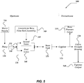
- Figure 5 illustrates a schematic view of one embodiment of a pump-driven espresso machine 500 that includes brew flow rate regulating assembly 536 that may enable regulating a flow rate of water during at least a portion of an espresso brewing process, according to the invention.
- the upstream indicator, the downstream indicator, and the direction the arrow, between the upstream and downstream indicators, define the upstream/downstream convention used herein.
- dashed directional lines are used to illustrate at least electrical coupling and/or electrical communication of the components.
- the electrical coupling may include the ability to distribute electrical power and/or electrical signals that may enable the controlling or operation of the various components.
- directional solid lines are used to illustrate at least the fluid and/or pressure communication of the components.
- pressurized water may flow through espresso machine 500 at a flow rate denoted by f .
- f may vary during the espresso brewing process.
- the water flowing through espresso machine 500 may be delivered to coffee grounds stored in coffee grounds housing 520.
- the water delivered to the coffee grounds may pre-wet the coffee grounds and flow rate ⁇ may be equal to a first flow rate.
- the flow rate may vary during the pre-brew phase.
- ⁇ may be a function of time during at least the pre-brew phase.
- the average flow rate during the pre-brew phase may be equal to the first flow rate.
- the water delivered to the pre-wet coffee grounds may be extracted through the coffee grounds to produce espresso.
- the produced espresso may flow out of espresso machine 500 through espresso output 540.
- flow rate ⁇ during the extraction phase may be equal to a second flow rate.
- the flow rate may vary during the extraction phase.
- ⁇ may be a function of time during at least the extraction phase.
- the average flow rate during the extraction phase may be equal to the second flow rate.
- the second flow rate may be equal to or greater than the first flow rate.
- pressurized water flowing through espresso machine may be stored in brew tank 530 for a duration of time.
- pressurized water may be heated.
- the pressurized heated water may flow through giggleur 525 before being delivered to coffee grounds in coffee ground housing 520.
- giggleur 525 may include a flow limiting valve, such as a jet valve, or a nozzle.
- giggleur 225 may include an aperture or orifice.
- giggleur 225 may be characterized by at least a diameter, d 0 . In some embodiments, d 0 may be approximately 0.7 mm.
- water supply 516 may supply water to pump 526.
- pump 526 may pump at least a portion of the supplied water to brew flow rate regulating assembly 536.
- the water pumped into brew flow rate regulating assembly 536 may be pressurized at an initial pressure, P 0 .
- P 0 may vary between 1 and 15 bars.
- P 0 may be approximately 9 bars.
- P 0 may vary throughout the espresso brewing process. For instance, P 0 during the pre-brew phase may be less than P 0 during the extraction phase. In some embodiments, P 0 may be a function of time and vary continuously throughout the espresso brewing process.
- flow rate regulating assembly 536 may include at least first flow path 550 and second flow path 552.
- flow through first flow path 550 may be regulated by at least first valve 546.
- first valve 546 may be a needle valve.
- a diameter, or other defining linear dimension, of needle valve 550 may be adjusted to a first diameter, such as d 1 , prior to the espresso brewing process.
- d 1 may be less than giggleur 525 diameter d 0 .
- needle valve 546 may be adjusted so that d 1 is approximately 0.1 mm.
- needle valve 546 may be adjusted so that d 1 is within a range, including 0.01 mm to 0.6 mm.
- flow through second flow path 552 may be regulated by at least second valve 548.
- second valve 548 may be a solenoid valve.
- solenoid valve 548 may be closed during at least a portion of the espresso brewing process, such as the pre-brew phase.
- solenoid valve 548 may be open during at least another portion of the espresso brewing process, such as the extraction phase.
- controlling the opening and closing of solenoid valve 548 during the espresso brewing process may be enabled by at least controls for brew flow rate assembly 508.
- solenoid valve 548 When solenoid valve 548 is open, water may flow through second flow path 552. When solenoid valve 548 is closed, water may be blocked by at least a portion of solenoid valve 548, or a plunger included in solenoid valve 548, and prohibited from flowing through second flow path 552.
- second flow path when solenoid valve 548 is open, second flow path may be approximated as a pipe with second transverse diameter, such as d 2 , with regards to fluid dynamics.
- d 2 may be greater than d 1 .
- d 2 may be greater than giggleur 525 diameter d 0 . In at least one embodiment, d 2 may be less than giggleur 525 diameter d 0 .
- the flow rate through first flow path 550 may be denoted by ⁇ 1 , and may vary throughout the espresso brewing process.
- ⁇ 1 may depend upon at least one of pressure provided by pump 526 ( P 0 ), transverse diameter of first flow path 550 ( d 1 ), adjustment of needle valve 546, transverse diameter of second flow path 552 (d2), and whether solenoid valve 548 is open or closed.
- ⁇ 1 may depend upon at least d 0 , the diameter of giggleur 525.
- the flow rate through second flow path 552 may be denoted by ⁇ 2 , and may vary throughout the espresso brewing process.
- ⁇ 2 may depend upon at least one of pressure provided by pump 526 ( P 0 ), transverse diameter of first flow path 550 ( d 1 ), adjustment of needle valve 546, transverse diameter of second flow path 552 (d 2 ), and whether solenoid valve 548 is open or closed.
- ⁇ 2 may dependent upon at least d 0 the diameter of giggleur 525.
- ⁇ 2 maybe equal to zero during at least a portion of the espresso brewing process.
- ⁇ 2 may be equal to zero during at least a portion of the pre-brew phase.
- the flow rate of water into brew flow rate regulating assembly 536 may equal the flow rate out of brew flow rate regulating assembly 536, and may be equal to ⁇ .
- ⁇ may depend upon at least ⁇ 1 and ⁇ 2 .
- f may depend upon at least a sum of ⁇ 1 and ⁇ 2 .
- ⁇ may depend upon at least one of pressure provided by pump 526 ( P 0 ), transverse diameter of first flow path 550 ( d 1 ), adjustment of needle valve 546, transverse diameter of second flow path 552 (d 2 ), and whether solenoid valve 548 is open or closed.
- ⁇ may depend upon at least d 0 , the transverse diameter of giggleur 525.
- espresso machine 500 may include brew pressure gauge 518.
- Brew pressure gauge 518 may indicate the pressure, P , between giggleur 525 and coffee grounds housing 520.
- P may vary during the espresso brewing process.
- P may depend upon ⁇ .
- P may depend upon at least one of pressure provided by pump 526 ( P 0 ), transverse diameter of first flow path 550 ( d 1 ), adjustment of needle valve 546, transverse diameter of second flow path 552 (d 2 ), and whether solenoid valve 548 is open or closed.
- P may depend upon at least d 0 , the diameter of giggleur 525.
- ⁇ may depend upon at least d 0 , the diameter of giggleur 525.
- P may at least approximate the pressure if the water being delivered to the coffee grounds.
- Figure 6 illustrates one embodiment of brew flow rate regulation assembly 600, which includes brew regulation assembly input 642 and brew regulation assembly output 644.
- the arrows in Figure 6 indicate the direction and magnitude of pressurized water flowing into and out of brew flow rate regulation assembly 600.
- water flowing into brew regulation assembly input 642 may flow through at least a first flow path (not shown) in assembly block 670.
- Valve assembly 646 may regulate the flow rate of water through the first flow path in assembly block 670.
- valve assembly 646 may be a needle valve assembly.
- the flow rate of water through the first flow path may be regulated by at least adjusting needle valve adjustment knob 672.
- needle valve adjustment knob 672 may be adjusted so that first flow path has an equivalent transverse diameter of d 1 .
- needle valve adjustment knob 672 may be adjusted prior to an espresso brewing process.
- assembly block 670 may include a second flow path (not shown).
- the second flow path may have an equivalent transverse diameter of d 2 .
- d 2 may be greater than d 1 .
- the second flow path may be a by-pass of the first flow path.
- another valve may regulate the flow rate through the second flow path.
- the other valve may be an electro-mechanical valve, such as a solenoid valve. When the solenoid valve is open, at least a portion of the water flowing into brew regulation assembly input 642 may flow through the second flow path. When the solenoid valve is closed, water may be prevented from flowing through the second flow path.
- Solenoid valve may include solenoid housing 674, which may house a solenoid employed to provide the mechanical force required to open and close the solenoid valve.
- Solenoid valve may include at least one solenoid valve electrical input 676, which may provide the electrical power required to energize the solenoid housed in solenoid housing 674.
- solenoid valve may include a plurality of solenoid valve electrical inputs 676, one of which may include a line to ground. Another electrical input may carry an electrical signal to trigger the opening and closing of the solenoid valve.
- the first flow path maybe substantially perpendicular to the second flow path.
- the needle valve regulating flow though the first flow path may be substantially perpendicular to the solenoid valve regulating flow rate through the second flow path.
- the first flow path may be substantially parallel to the second flow path.
- the needle valve may be substantially parallel to the solenoid valve.
- a first plunger included in the needle valve may be substantially perpendicular to a second plunger included in the solenoid valve.
- FIG 7 illustrates a logical flow diagram generally showing one embodiment of an espresso brewing process 700 that includes regulating a brew flow rate with an espresso machine, such as espresso machine 200 of Figure 2 .
- espresso brewing process 700 includes at least two phases: a pre-brew phase and an extraction phase.
- the pre-brew phase occurs prior to the extraction phase.
- coffee grounds that are used to brew espresso may be pre-wetted with heated water.
- a first volume of water may be delivered to the coffee grounds, by the espresso machine, where a brew flow rate may be equal to a first brew flow rate.
- the first volume of water delivered to the coffee grounds during the pre-brew phase may be significant enough to saturate the coffee grounds. In some of the various embodiments, the first volume of water delivered to the coffee grounds during the pre-brew phase, may induce an out-gassing reaction within the coffee grounds.
- espresso brewing process 700 may transition to the extraction phase.
- the espresso machine may deliver a second volume of water to the pre-wetted coffee grounds at a brew flow rate equal to a second brew flow rate.
- the second volume of water delivered to the coffee grounds during the extraction phase, and at the second brew flow rate, may be extracted through the pre-wetted coffee grounds to produce brewed espresso from the out-gassed coffee grounds.
- the second brew flow rate may be greater than or equal to the first brew flow rate.
- the first volume of water delivered to the coffee grounds may be heated water. In at least one embodiment, the first volume of water delivered to the coffee grounds may be pressurized water. In at least one embodiment, the second volume of water delivered to the coffee grounds may be heated water. In at least one embodiment, the second volume of water delivered to the coffee grounds may be pressurized water.
- the pressure (P) between a giggleur, such as giggleur 525 of Figure 5 , and the coffee grounds housed in coffee ground housing, such as coffee ground housing 520 of Figure 5 may vary during espresso brewing process 700.
- P may be varied by at least varying the flow rate of water delivered to the espresso grounds.
- P may be varied by at least varying the pressure P 0 delivered by a pump, such as pump 526 of Figure 5 .
- P may be a function of time, such as P(t) , during espresso brewing process 700.
- P may be a function of the volume of water that flows to the coffee grounds.
- a first volume delivered at a first flow rate may brew at an average first pressure.
- the flow rate is adjusted to a second flow rate; the average pressure may transition to a second average pressure.
- the flow rate may be adjusted to a third flow rate, during the remainder of the extraction, which may result in a third average pressure during the remainder of the extraction.
- controlling and the timing of the adjustment of flow rate, volume of water delivered, pressure, pump speed, and the like may be manually controlled by a barista and/or automatically adjusted by processor device included in the espresso machine.
- a measurement of the volume of water delivered to the coffee grounds may be enabled by at least a flow meter.
- a measurement of the flow rate may be enabled by at least the flow meter.
- the first volume of water may be within a first window, such as 0-7 milliliters (ml).
- the second volume of water may be within a second window, such as 7-15 ml.
- Figure 8 illustrates three examples of P as a function of time, or pressure profiles, resulting from various embodiments of espresso brewing process 700.
- the examples of the pressure profiles are discussed in the context of espresso brewing process 700.
- By varying the nature and shape of the pressure profile resulting from espresso brewing process 700 one may vary the taste of extracted shot of espresso.
- One may vary at least the nature and/or shape of the pressure profile by regulating the brew flow rate during the espresso brew process 700.
- one may vary at least the nature and/or shape of the pressure profile by varying the flow rate, pressure, and total volume of the first volume of water delivered to the coffee grounds during the espresso brew process 700.
- Process 700 begins, after a start block, at block 702 where a brew flow rate is adjusted to a first brew flow rate.
- the adjusted brew flow rate refers to the rate that the espresso machine delivers heated pressurized water to coffee grounds that are used to brew espresso.
- the brew flow rate is adjusted by employing at least a brew flow rate regulating assembly, such as brew flow rate regulating assembly 536 of Figure 5 .
- the brew flow rate regulating assembly may be controlled by controls for brew flow rate regulating assembly, such as controls for brew flow rate regulating assembly 508 of Figure 5 .
- controls for brew flow rate regulating assembly may include at least a brew handle, such as brew handle 108 of Figure 1 .
- a user of the espresso machine is enabled to adjust the brew flow rate of the espresso machine by adjusting a position of the brew handle.
- the brew flow rate may be adjusted to the first brew flow rate by adjusting the position of the brew handle to a first position.
- adjusting the brew flow rate to the first brew flow rate may include at least adjusting a first valve included in the brew flow rate regulating assembly.
- adjusting the brew flow rate to the first brew flow rate may include at least adjusting a second valve included in the brew flow rate regulating assembly.
- adjusting the brew flow rate to the first brew flow rate may include at least adjusting another valve included in the espresso machine.
- adjusting the brew flow rate to the first brew flow rate may include at least opening or closing the other valve included in the espresso machine.
- adjusting a valve may include at least one of opening the valve, closing the valve, or adjusting an aperture size on an aperture included in the valve.
- adjusting the brew flow rate to a first brew flow rate may include opening another valve, where the other valve enables water pressurized by a pump, such as pump 526 of Figure 5 , to flow into the brew flow rate regulating assembly.
- the other valve prior to block 702, the other valve may be in a closed position.
- the first brew flow rate may be limited by at least a first needle valve, such as needle valve 546 of Figure 5 , where the first needle valve was adjusted prior to block 702.
- the pre-adjusted first needle valve may be included in the brew flow rate regulating assembly.
- the adjusted first needle valve may be in an open position and adjusted to a first aperture size. The first needle valve may permit the flow, but regulate the flow rate, of water through a first flow path in the brew flow rate regulation assembly, such as first flow path 550 of Figure 5 .
- the first brew flow rate may be limited by at least an electro-mechanical valve, such as a solenoid valve.
- the solenoid valve such as solenoid valve 548 of Figure 5
- the solenoid valve may be included in the brew flow rate regulating assembly.
- the solenoid valve may be in a closed position at block 702. The closed solenoid valve may prohibit the flow of water through a second flow path in the brew flow rate regulation assembly, such as second flow path 552 in Figure 5 .
- the first brew flow rate may be dependent on at least the sum a flow rate through the first flow path and the flow rate through second flow path.
- the first brew flow rate may be equal to at least the sum of a flow rate through the first flow path and another flow rate through the second flow path.
- the coffee grounds being used to brew espresso may be pre-wetted.
- the coffee grounds being used to brew espresso may be out-gassed grounds.
- the coffee grounds may be housed within a coffee ground basket within a coffee ground housing, such as coffee ground housing 520 of Figure 5 .
- the coffee ground housing may be included in a portafilter assembly, such as portafilter assembly 110 of Figure 1 .
- the espresso machine delivers heated pressurized water to the coffee grounds, at the first brew flow rate, in order to pre-wet and/or out-gas the coffee grounds.
- pre-wetting the coffee grounds, prior to brewing espresso with the coffee grounds at least induces an out-gassing reaction within the coffee grounds.
- Pressure profile 802 of Figure 8 illustrates one example of the pressure, P , as a function of time during espresso brewing process 700.
- P may ramp up from zero to approximately a pressure value of P 1 .
- the first needle valve prior to espresso brewing process 700, the first needle valve may be adjusted to provide the first volume of water, where the first volume of water is sufficient to saturate the coffee grounds within a pre-determined time interval, such as t 0 .
- t 0 may depend upon the coarseness of the coffee grounds.
- t 0 may vary between 1 and 30 seconds.
- t 0 may be long enough to allow the delivered water to saturate the coffee grounds.
- pressure P may be limited to a value of P 1 , during the pre-brew phase, at least because the solenoid valve is closed during the pre-brew phase and accordingly, water is not flowing through the second flow path.
- pressure P may be limited to a value of P 1 , during the pre-brew phase, at least because a diameter of the giggleur is greater than the diameter of the needle valve within the brew flow rate regulation assembly.
- pressure value P 1 may not be great enough to force the delivered water through the coffee grounds.
- the choice of t 0 , P 1 , the volume of the first volume of water delivers, and other brewing parameters may greatly affect the taste of the brewed espresso.
- Pressure profile 804 and 806 show two other examples of pressure as a function of time that may be achieved by some embodiments, by varying the flow rate, the volumes of the first volume and second volumes, and/or pressure provided by the pump during espresso brewing process 700, and the durations for which at least the pre-brew phase and the extraction phase last.
- the shape of the pressure curve during the pre-brew phase may greatly affect the taste and texture of the brewed espresso.
- the pre-brew phase of espresso brewing process 700 lasts longer than t 0 .
- the transition to the extraction phase may be signaled by at least a discontinuity in the pressure as a function of time curve.
- the transition to the extraction phase may be signaled by at least an increase in the first derivative of the pressure as a function of time curve.
- the heated pressurized water may be delivered, at the first brew flow rate, to the coffee grounds, until at decision block 706, it is determined that the coffee grounds have become saturated with the delivered water.
- an indication that the coffee grounds have become saturated includes at least a portion of the first volume of water delivered at the first brew flow rate begins to flow out of an espresso output, such as espresso output 540 of Figure 5 .
- the espresso machine may include a mirror to observe when water begins to flow out of the espresso output.
- the espresso output may be an aperture in the portafilter assembly.
- the pre-brew phase may be associated with at least pre-wetting the coffee grounds at the first brew flow rate. In at least one embodiment, the pre-brew phase may be associated with at least one of the first brew flow rate. In some embodiments, the pre-brew phase may be terminated at block 706 and the process 700 may proceed to block 708.
- the brew flow rate may be adjusted to a third flow rate before proceeding to block 708.
- the brew flow rate may be adjusted to the third brew flow rate by adjusting the position of the brew handle to a third position.
- the third position of the brew handle may be an off position.
- the third flow rate may be equal to an off value.
- the flow of water through the espresso machine may be halted and the brewing process may wait a duration before proceeding to block 708.
- a duration may occur after the pre-brew phase is terminated, but before the brewing process transitions to the extraction phase. During the duration, an out-gassing reaction may be occurring in the coffee grounds. After the duration, process 700 may proceed to block 708.
- Pressure profile 804 illustrates a duration, after the pre-brew phase, but prior to the extraction phase.
- the slope, or first time derivative, of the pressure curve may approximate a value close to zero during a duration phase.
- the increase in the slope of pressure profiles 802, 804, and 806 may signify a transition to the extraction phase.
- the brew flow rate may be adjusted to a second brew flow rate.
- the brew flow rate may be adjusted to the second brew flow rate by adjusting the position of the brew handle to a second position.
- the second brew flow rate may be greater than the first flow rate.
- adjusting the brew flow rate to the second brew flow rate may include at least adjusting a first valve included in the brew flow rate regulating assembly.
- adjusting the brew flow rate to the second brew flow rate may include at least adjusting a second valve included in the brew flow rate regulating assembly.
- adjusting the brew flow rate to the second brew flow rate may include at least adjusting another valve included in the espresso machine.
- the second brew flow rate may be limited by at least the first needle valve. In some of the various embodiments, the second brew flow rate may be limited by at least the solenoid valve. In some of the embodiments, the solenoid valve may be in an open position at block 708. In some embodiments, the solenoid valve may be adjusted or transitioned from a closed position to an open position at block 708. The open solenoid valve may allow for the flow of water through the second flow path in the brew flow rate regulation assembly. In some embodiments, the second brew flow rate may be at least the sum a flow rate through the first needle valve and the solenoid valve.
- increasing the flow rate from the first brew flow rate to the second brew flow rate may increase the pressure, P.
- Pressure profile 802 of Figure 8 demonstrates, that at t 0 , where espresso brewing process 700 transitions from the pre-brew phase to the extraction phase, the pressure increases from value of P 1 to an increased value of P 2 . In some embodiments, this transition may resemble a step function. In other embodiments, the transition in pressure may be continuous and/or may occur more gradually. Pressure profiles 804 and 806 also demonstrate a step function indicating where espresso brew process has transitioned to the extraction phase.
- the transition of pressure at t 0 may occur at least because the solenoid valve may have transitioned from a closed state to an open state.
- water may now flow through at least the second flow path.
- the diameter of the giggleur may be less than the diameter of the second flow path.
- the diameter of the giggleur may be less than the sum of the diameter of the second flow path and the diameter of the first needle valve.
- P 1 may be less than P 0 , the pressure supplied by the pump.
- P 1 may be approximately equal to P 0 .
- P 1 may be great enough to force the water delivered to the espresso grounds through the espresso grounds to produce espresso.
- a second volume of heated pressurized water may be delivered to the pre-wetted coffee grounds at the second brew flow rate.
- the pre-wetted grounds may be saturated grounds.
- at least a portion of the second volume of heated pressurized water delivered to the coffee grounds at block 710 may be extracted through the coffee grounds to produce espresso.
- the produced espresso may flow out of the espresso machine through the espresso output. Extraction of espresso may continue, until it is determined that the extraction is complete at decision block 712.
- the extraction phase may be associated with at least extracting the heated pressurized water through the pre-wetted coffee grounds, where the second volume of water has been delivered to the pre-wetted coffee grounds at the second brew flow rate.
- the extraction phase may be associated with at least one of the second brew flow rate.
- the pressure profile may remain at an approximately constant pressure during the extraction phase.
- pressure profile 802 illustrates that the pressure remains constant at P 1 pressure value during until the extraction phase is terminated at t 1 .
- the extraction phase may last for a finite duration, such as t 1 - t 0 .
- the pressure profile may vary during the extraction phase.
- both pressure profiles 804 and 806 illustrate the pressure rolling off, or decreasing, before espresso brewing process 700 is terminated. In at least on embodiment, this rolling off may be enabled by at least varying the second flow rate during the extraction phase.
- varying the pressure may be enabled by at least varying the pump supplied pressure, P 0 .
- Some embodiments may vary a rotational speed of the pump during espresso brewing process 700. The shape and duration of the extraction phase may greatly affect the taste of the produces espresso.
- the first volume of water delivered to the coffee grounds, at the first flow rate, during the pre-brew phase may be less than or equal to the second volume of water delivered to the coffee grounds, at the second flow rate, during the extraction phase. In at least one alternative embodiment, the first volume of water delivered to the coffee grounds, at the first flow rate, during the pre-brew phase may be greater than the second volume of water delivered to the coffee grounds, at the second flow rate, during the extraction phase.
- the brew flow rate may be adjusted to an off value, to terminate espresso brewing process 700 and so that water does not flow through the espresso machine, after the espresso shot has been brewed.
- process 700 may transition to block 714 at time t 1 .
- the brew flow rate may be adjusted to the off value by adjusting the position of the brew handle to a third position or to an off position.
- adjusting the brew flow rate to the off value may include at least adjusting a first valve included in the brew flow rate regulating assembly.
- adjusting the brew flow rate to the off value may include at least adjusting a second valve included in the brew flow rate regulating assembly.
- adjusting the brew flow rate to the off value may include at least adjusting another valve included in the espresso machine.
Landscapes
- Engineering & Computer Science (AREA)
- Food Science & Technology (AREA)
- Life Sciences & Earth Sciences (AREA)
- Chemical & Material Sciences (AREA)
- Polymers & Plastics (AREA)
- Mechanical Engineering (AREA)
- Physics & Mathematics (AREA)
- Fluid Mechanics (AREA)
- Apparatus For Making Beverages (AREA)
Claims (8)
- Verfahren (700) zur Herstellung eines gebrühten Kaffeegetränks unter Verwendung einer Espressomaschine (100, 200, 500), wobei das Verfahren (700) umfasst:Einstellen einer Brühdurchflussrate von unter Druck stehendem Wasser innerhalb der Espressomaschine (100, 200, 500) auf eine erste Durchflussrate (702), wobei das Einstellen der Brühdurchflussrate des unter Druck stehenden Wassers durch eine Brühdurchflussratenregulierungsanordnung (236, 300, 400, 536, 600) ermöglicht wird, die einen ersten Durchflussweg (350, 450, 550) und einen zweiten Durchflussweg (352, 452, 552) einschließt, wobei sowohl der erste Durchflussweg (350, 450, 550) als auch der zweite Durchflussweg (352, 452, 552) so konfiguriert und angeordnet sind, dass sie mindestens einen Teil des unter Druck stehenden Wassers aufnehmen;Pumpen eines ersten Volumens des unter Druck stehenden Wassers durch ein Giggleur (225, 525) mit der ersten Durchflussrate, um das erste Volumen von unter Druck stehendem Wasser dem Kaffeemehl zuzuführen und das Kaffeemehl (704) vorzunässen, wobei das Giggleur (225, 525) in Fluidverbindung mit der Brühdurchflussratenregulierungsanordnung (236, 300, 400, 536, 600) steht;Einstellen der Brühdurchflussrate des unter Druck stehenden Wassers auf eine zweite Durchflussrate (708), wobei die zweite Durchflussrate größer ist als die erste Durchflussrate ist;Pumpen eines zweiten Volumens des unter Druck stehenden Wassers durch das Giggleur (225, 525) mit der zweiten Durchflussrate, um das zweite Volumen von unter Druck stehendem Wasser dem vorgenässten Kaffeemehl zuzuführen; undExtrahieren von mindestens einem Teil des zugeführten zweiten Volumens an unter Druck stehendem Wasser durch das vorgenässte Kaffeemehl, um das gebrühte Kaffeegetränk (710) herzustellen.
- Verfahren (700) nach Anspruch 1, wobei die erste Durchflussrate durch ein erstes Ventil (346, 446, 546, 646) und die zweite Durchflussrate durch ein zweites Ventil (348, 448, 548) geregelt wird.
- Verfahren (700) nach Anspruch 1, wobei das Einstellen der Brühdurchflussrate von unter Druck stehendem Wasser auf die zweite Durchflussrate (708) das Überführen eines Ventils (346, 446, 546, 646, 348, 448, 548) von einer geschlossenen Position in eine offene Position einschließt.
- Verfahren (700) nach Anspruch 1, wobei das Einstellen der Brühdurchflussrate des unter Druck stehenden Wassers auf die erste Durchflussrate (702) das Sperren der Durchflusses des unter Druck stehenden Wassers durch den zweiten Durchflussweg (352, 452, 552) einschließt.
- Verfahren (700) nach Anspruch 1, wobei die Brühdurchflussratenregulierungsanordnung (236, 300, 400, 536, 600) zwischen einer Pumpe (226, 526) und dem Giggleur (225, 525) angeordnet ist.
- Verfahren (700) nach Anspruch 1, das ferner das Positionieren eines Brühgriffs (108) umfasst, der so konfiguriert und angeordnet ist, dass er ein Ventil (346, 446, 546, 646, 348, 448, 548) stromaufwärts von dem Giggleur (225, 525) öffnet.
- Verfahren (700) nach Anspruch 1, wobei das erste Volumen des unter Druck stehenden Wassers dem Kaffeemehl mit einem ersten durchschnittlichen Druck zugeführt wird und das zweite Volumen des unter Druck stehenden Wassers dem vorgenässten Kaffeemehl mit einem zweiten durchschnittlichen Druck zugeführt wird, und wobei der zweite durchschnittliche Druck größer als der erste durchschnittliche Druck ist.
- Verfahren (700) nach Anspruch 1, wobei das Einstellen der Brühdurchflussrate des unter Druck stehenden Wassers auf die zweite Durchflussrate das Erhöhen eines Druckwerts von mindestens einem Teil des unter Druck stehenden Wassers einschließt, der sich stromabwärts des Giggleurs (225, 525) befindet.
Applications Claiming Priority (2)
| Application Number | Priority Date | Filing Date | Title |
|---|---|---|---|
| US14/015,823 US9433318B2 (en) | 2013-08-30 | 2013-08-30 | System and apparatus for regulating flow rate in an espresso machine |
| PCT/US2014/053536 WO2015031828A1 (en) | 2013-08-30 | 2014-08-29 | System, method, and apparatus for regulating flow rate in an espresso machine |
Publications (3)
| Publication Number | Publication Date |
|---|---|
| EP3038502A1 EP3038502A1 (de) | 2016-07-06 |
| EP3038502A4 EP3038502A4 (de) | 2017-04-19 |
| EP3038502B1 true EP3038502B1 (de) | 2021-11-17 |
Family
ID=52583604
Family Applications (1)
| Application Number | Title | Priority Date | Filing Date |
|---|---|---|---|
| EP14839762.3A Active EP3038502B1 (de) | 2013-08-30 | 2014-08-29 | Verfahren zur durchflussregulierung in einer espressomaschine |
Country Status (6)
| Country | Link |
|---|---|
| US (2) | US9433318B2 (de) |
| EP (1) | EP3038502B1 (de) |
| DK (1) | DK3038502T3 (de) |
| ES (1) | ES2906125T3 (de) |
| PT (1) | PT3038502T (de) |
| WO (1) | WO2015031828A1 (de) |
Cited By (1)
| Publication number | Priority date | Publication date | Assignee | Title |
|---|---|---|---|---|
| DE102020206808B4 (de) | 2020-05-29 | 2024-07-18 | Bellezza Milano S.R.L. | Brühgruppe für eine Espressomaschine und Espressomaschine mit einer entsprechenden Brühgruppe |
Families Citing this family (24)
| Publication number | Priority date | Publication date | Assignee | Title |
|---|---|---|---|---|
| US9433318B2 (en) | 2013-08-30 | 2016-09-06 | Seattle Espresso Machine Corporation | System and apparatus for regulating flow rate in an espresso machine |
| US9364117B2 (en) | 2013-08-30 | 2016-06-14 | Seattle Espresso Machine Corporation | Method for regulating flow rate in an espresso machine |
| US10537206B2 (en) * | 2015-02-13 | 2020-01-21 | G. Bezzera S.R.L. | Machine for coffee-based beverages |
| US10271677B2 (en) * | 2015-04-01 | 2019-04-30 | Synesso, Inc. | Apparatus and method for optimizing the brewing of espresso |
| US10034574B2 (en) * | 2015-04-01 | 2018-07-31 | Synesso, Inc. | Apparatus and method for controlling an espresso machine |
| US10463054B2 (en) | 2015-05-20 | 2019-11-05 | Teaspressa Llc | Methods of tea extraction |
| NL2015068B1 (en) * | 2015-07-01 | 2017-01-30 | Douwe Egberts Bv | A system for heating and frothing a beverage, a device for heating and frothing a beverage suitable for being used in such a system, a froth wand suitable for being used in such a system and a method of preparing a beverage using such a system. |
| US20170027367A1 (en) * | 2015-07-31 | 2017-02-02 | Remington Designs, Llc | Devices and methods for beverage brewer pressure regulation |
| DE102015217997A1 (de) * | 2015-09-18 | 2017-03-23 | Franke Kaffeemaschinen Ag | Brühvorrichtung zum Zubereiten eines Heißgetränks |
| EP3364835B1 (de) * | 2015-10-23 | 2019-12-04 | Eurek S.r.l. | Verfahren, maschine und kessel zur zubereitung von getränken |
| US9907426B2 (en) | 2016-05-20 | 2018-03-06 | Seattle Espresso Machine Corporation | Method for generation of superheated steam for the preparation of a beverage |
| US10390654B2 (en) | 2016-05-20 | 2019-08-27 | Seattle Espresso Machine Corporation | Generation of superheated steam for the preparation of a beverage |
| USD807096S1 (en) * | 2016-05-20 | 2018-01-09 | Seattle Espresso Machine Corporation | Espresso machine |
| IT201700054448A1 (it) * | 2017-05-19 | 2018-11-19 | Coffee Innovations Pty Ltd C/O Green & Sternfeld | Apparecchio e metodo per schiumare una quantita' di latte |
| CN111065277A (zh) | 2017-07-11 | 2020-04-24 | 努布鲁有限责任公司 | 改善意式浓缩咖啡一致性的方法和装置 |
| CN115736642B (zh) * | 2017-10-20 | 2025-02-25 | Cma佩尔咖啡机有限责任公司 | 用于制备饮料的机器和用于控制该机器中饮料递送的方法 |
| IT201800006140A1 (it) | 2018-06-08 | 2019-12-08 | Procedimento per migliorare la costanza del grado di concentrazione in una macchina per caffe espresso e relativa macchina per caffè espresso | |
| US20200229631A1 (en) * | 2019-01-17 | 2020-07-23 | Davide CAPPELLINI | Espresso coffee machine and relative device for controlling the emulsion of the coffee-based beverage |
| USD985992S1 (en) * | 2019-10-09 | 2023-05-16 | Gruppo Cimbali S.P.A. | Coffee machine |
| CN114176400B (zh) * | 2020-09-14 | 2022-11-22 | 宁波方太厨具有限公司 | 变压萃取装置及包括其的咖啡机和茶叶萃取机 |
| IT202100009692A1 (it) * | 2021-04-16 | 2022-10-16 | La San Marco S P A | Macchina per caffè e procedimento di erogazione di detto caffè |
| US12114802B2 (en) * | 2021-04-20 | 2024-10-15 | Omri ALMAGOR | Steam and heated liquid generation method and system for beverage system |
| IT202200015408A1 (it) * | 2022-07-21 | 2024-01-21 | La San Marco S P A | Macchina per caffè e procedimento di erogazione di detto caffè |
| CN120226912A (zh) * | 2023-12-31 | 2025-07-01 | 苏州咖乐美咖啡机科技有限公司 | 杯量确定方法、饮品机、电子设备及存储介质 |
Citations (2)
| Publication number | Priority date | Publication date | Assignee | Title |
|---|---|---|---|---|
| WO2012070002A1 (en) * | 2010-11-24 | 2012-05-31 | Rancilio Group S.p.A. | Coffee machine |
| EP2570056A1 (de) * | 2011-09-13 | 2013-03-20 | Jura Elektroapparate AG | Verfahren zum Erzeugen eines Kaffeegetränks sowie Kaffeeautomat zum Durchführen des Verfahrens |
Family Cites Families (68)
| Publication number | Priority date | Publication date | Assignee | Title |
|---|---|---|---|---|
| GB432075A (en) | 1933-10-14 | 1935-07-19 | John Bertram Morton Knutsen | Method of and means for the economic production of milk powder from whole milk |
| US2906193A (en) | 1956-08-29 | 1959-09-29 | Raymond E Mccauley | Coffee beverage making machine |
| US3835294A (en) | 1973-04-06 | 1974-09-10 | Binks Mfg Co | High pressure electric fluid heater |
| US4032748A (en) | 1975-10-10 | 1977-06-28 | Innovative Process Equipment, Inc. | Scale deposit removal arrangement for electric water heaters and vaporizers |
| IT7925959A0 (it) | 1979-09-25 | 1979-09-25 | Nascardi Piero | Macchina per caffe' espresso, ad uso famigliare, provvista di un doppio termostato, per laproduzione di caffe' e di vapore. |
| US4470999A (en) | 1982-02-01 | 1984-09-11 | Carpiac Joseph L | High speed, high volume coffee making apparatus and method |
| IT8321544U1 (it) | 1983-04-14 | 1984-10-14 | Nuova Faema Spa | Dispositivo dosatore dell'acqua per macchine per il caffe' espresso, munito di una girante. |
| US4714011A (en) | 1986-10-20 | 1987-12-22 | Ly Binh T | Portable beverage brewing apparatus |
| DE3815355A1 (de) | 1988-05-05 | 1989-11-16 | Krups Stiftung | Elektrisch betriebenes geraet zum zubereiten heisser getraenke, wie kaffee, tee od. dgl. |
| CH675819A5 (de) | 1988-06-10 | 1990-11-15 | Nestle Sa | |
| DE4204746C2 (de) | 1992-02-18 | 2002-01-17 | Eugster Frismag Ag Romanshorn | Kaffeemaschine |
| DE4220986A1 (de) | 1992-06-26 | 1994-01-05 | Gotthard Dipl Ing Mahlich | Vorrichtung zum Zubereiten von Milchschaum für Cappuccino |
| DE19520121A1 (de) | 1995-06-01 | 1996-12-05 | Braun Ag | Verfahren zur Zubereitung von heißen Getränken und Vorrichtung zur Durchführung des Verfahrens |
| USD395975S (en) | 1995-12-29 | 1998-07-14 | Gaggia Espanola, S.A. | Coffee machine |
| US6829981B2 (en) * | 1998-08-11 | 2004-12-14 | Food Equipment Technologies Company, Inc. | Coffee brewer with independent control of dispense period and batch quantity and method |
| IT1306509B1 (it) | 1998-11-24 | 2001-06-11 | Alberto Rolla | Macchina da caffe' espresso |
| EP1180542A1 (de) | 1999-03-03 | 2002-02-20 | Toyoda Techno Co., Ltd | Verfahren zur behandlung von abfällen |
| IT1309110B1 (it) | 1999-10-14 | 2002-01-16 | Rancilio Macchine Caffe | Macchina per caffe'. |
| US20080173260A1 (en) | 2001-04-12 | 2008-07-24 | Jack Lange | Heat transfer from a source to a fluid to be heated using a heat driven loop |
| DE10148931A1 (de) | 2001-10-04 | 2003-04-24 | Eugster Frismag Ag Romanshorn | Espressomaschine mit einem drehbaren, keramischen Scheibenventil als selektiver Wasser-/Dampfverteiler |
| US7032502B2 (en) * | 2002-09-27 | 2006-04-25 | Simatelex Manufactory Co. Ltd. | Coffee maker |
| USD497510S1 (en) | 2002-10-22 | 2004-10-26 | Quality Espresso, S.A. | Espresso machine |
| US7231937B2 (en) * | 2003-05-27 | 2007-06-19 | Greene Ralph G | Automatic shutoff valve |
| US7424983B2 (en) | 2003-09-04 | 2008-09-16 | Quantum Corporation | Tape cartridge soft load system |
| US7444926B2 (en) | 2003-09-09 | 2008-11-04 | Nottingham John R | Apparatus for brewing and method for making the same |
| EP1731849A4 (de) | 2003-12-10 | 2013-09-18 | Panasonic Corp | Wärmetauscher und reinigungsvorrichtung damit |
| GB2413480B (en) | 2004-02-17 | 2006-08-30 | Kraft Foods R & D Inc | An insert and a system for the preparation of beverages |
| JP4330488B2 (ja) | 2004-05-12 | 2009-09-16 | 達實 小野 | 過熱蒸気を利用した加熱処理装置 |
| US20050274738A1 (en) | 2004-05-26 | 2005-12-15 | Tomsic Steven F | System and method to heat and dispense water |
| US8225961B2 (en) * | 2004-08-25 | 2012-07-24 | Bunn-O-Matic Corporation | Multiple hot water dispensing system |
| EP1676509A1 (de) | 2004-12-30 | 2006-07-05 | Rhea Vendors S.p.A. | Verfahren und Vorrichtung zur Steuerung der Vorbereitung von Brühgetränke |
| USD551487S1 (en) | 2005-04-29 | 2007-09-25 | Gruppo Cimbali S.P.A. | Expresso coffee machine |
| CA2580317A1 (en) * | 2006-03-02 | 2007-09-02 | Bunn-O-Matic Corporation | Brew strength control |
| CN101431928A (zh) | 2006-03-31 | 2009-05-13 | C&D佐迪阿克公司 | 饮料制造机 |
| USD561523S1 (en) | 2006-06-23 | 2008-02-12 | Illycaffe'spa Con Unico Socio | Hand lever for espresso coffee machines |
| US20080000357A1 (en) | 2006-06-30 | 2008-01-03 | Frank Yang | Hot beverage brewing device |
| EP1882433B1 (de) | 2006-07-24 | 2008-07-23 | Gruppo Cimbali S.p.A. | Kaffeemaschine mit Ausgabevorrichtung mit unabhängiger Heizung |
| ITFI20060244A1 (it) | 2006-10-04 | 2008-04-05 | Saeco Ipr Ltd | Macchina per la produzione di caffe' o simili e relativo metodo |
| EP1944404A1 (de) | 2006-12-18 | 2008-07-16 | Koninklijke Philips Electronics N.V. | Ein Gerät zur Versorgung mit überhitztem Wasser |
| US8045469B2 (en) | 2006-12-18 | 2011-10-25 | Research In Motion Limited | System and method for adjusting transmission data rates to a device in a communication network |
| DE102007010901A1 (de) | 2007-03-06 | 2008-09-11 | Pav Patentverwertung Kg | Heißwassereinheit für einen Heißgetränkezubereiter mit Milchschäumer |
| ES2349077T3 (es) * | 2007-03-13 | 2010-12-27 | Rancilio Macchine Per Caffe' S.P.A. | Dispositivo de suministro de agua caliente para máquinas de café. |
| EP2050368B1 (de) | 2007-10-16 | 2010-04-14 | Gruppo Cimbali S.p.A. | Kaffeemaschine mit Spender für ein fertiges Getränk auf Schokoladenbasis |
| CN101827547A (zh) * | 2007-10-16 | 2010-09-08 | 埃格罗咖啡系统公司 | 具有至少两个冲泡组的咖啡机 |
| USD592003S1 (en) | 2007-11-10 | 2009-05-12 | Gruppo Cimbali S.P.A. | Coffee machine |
| USD589739S1 (en) | 2008-04-11 | 2009-04-07 | Gruppo Cimbali S.P.A. | Coffee machine |
| CN102046049B (zh) | 2008-04-30 | 2013-08-21 | 拉玛祖克有限公司 | 一种具有预泡制装置的爱斯普利索咖啡机 |
| ITFI20080198A1 (it) | 2008-10-15 | 2010-04-16 | Saeco Ipr Ltd | "macchina da caffe'" |
| CH700103B1 (de) | 2008-12-10 | 2020-07-31 | Steiner Ag Weggis | Kaffeemaschine. |
| RU2552985C2 (ru) | 2008-12-30 | 2015-06-10 | Нестек С.А. | Способ заваривания чайных листьев, содержащихся в капсуле |
| ITPO20090011U1 (it) | 2009-10-23 | 2011-04-25 | Marzocco Srl | Macchina per caffe' espresso perfezionata |
| JP2011125221A (ja) | 2009-12-15 | 2011-06-30 | Yaizu Suisankagaku Industry Co Ltd | 抽出物の製造方法 |
| AU2011209447B2 (en) | 2010-01-29 | 2015-08-20 | Société des Produits Nestlé S.A. | Capsule and system for preparing a beverage by centrifugation in a beverage production device |
| RU2571357C2 (ru) | 2010-05-11 | 2015-12-20 | Бревилл Пти Лимитед | Способ работы кофеварки эспрессо и устройство для его осуществления |
| USD672998S1 (en) | 2010-11-26 | 2012-12-25 | Rancilio Group S.p.A. | Coffee maker |
| TR201202636U (tr) | 2011-03-14 | 2012-10-22 | Cupsystem Company B.V. | Arap tipi kahveli bir içeceğin hazırlanması için sistem. |
| JP6087955B2 (ja) | 2011-12-30 | 2017-03-01 | ネステク ソシエテ アノニム | マルチシステム飲料マシン |
| USD695052S1 (en) | 2012-06-07 | 2013-12-10 | Nuova Simonelli S.P.A. | Espresso machine |
| US9364117B2 (en) | 2013-08-30 | 2016-06-14 | Seattle Espresso Machine Corporation | Method for regulating flow rate in an espresso machine |
| US9433318B2 (en) | 2013-08-30 | 2016-09-06 | Seattle Espresso Machine Corporation | System and apparatus for regulating flow rate in an espresso machine |
| USD740600S1 (en) | 2014-04-02 | 2015-10-13 | Mars Drinks Uk Ltd. | Drink machine |
| USD758778S1 (en) | 2014-05-12 | 2016-06-14 | Rancilio Group S.p.A. | Coffee machine |
| CN103976659A (zh) | 2014-05-16 | 2014-08-13 | 冯海涛 | 智能型饮水加热装置 |
| CN104751906A (zh) | 2015-02-13 | 2015-07-01 | 中国科学院近代物理研究所 | 热交换系统和核反应堆系统 |
| US10034574B2 (en) | 2015-04-01 | 2018-07-31 | Synesso, Inc. | Apparatus and method for controlling an espresso machine |
| US20160353786A1 (en) | 2015-04-16 | 2016-12-08 | Elizabeth McHugh | Compositions and Methods to create natural curing foods |
| TWD178799S (zh) | 2015-07-17 | 2016-10-11 | Wmf集團公司 | 義式咖啡機 |
| US10247409B2 (en) | 2015-11-04 | 2019-04-02 | Conocophillips Company | Remote preheat and pad steam generation |
-
2013
- 2013-08-30 US US14/015,823 patent/US9433318B2/en active Active
-
2014
- 2014-08-29 PT PT148397623T patent/PT3038502T/pt unknown
- 2014-08-29 DK DK14839762.3T patent/DK3038502T3/da active
- 2014-08-29 EP EP14839762.3A patent/EP3038502B1/de active Active
- 2014-08-29 ES ES14839762T patent/ES2906125T3/es active Active
- 2014-08-29 WO PCT/US2014/053536 patent/WO2015031828A1/en not_active Ceased
-
2016
- 2016-08-02 US US15/226,300 patent/US10362892B2/en active Active
Patent Citations (2)
| Publication number | Priority date | Publication date | Assignee | Title |
|---|---|---|---|---|
| WO2012070002A1 (en) * | 2010-11-24 | 2012-05-31 | Rancilio Group S.p.A. | Coffee machine |
| EP2570056A1 (de) * | 2011-09-13 | 2013-03-20 | Jura Elektroapparate AG | Verfahren zum Erzeugen eines Kaffeegetränks sowie Kaffeeautomat zum Durchführen des Verfahrens |
Cited By (1)
| Publication number | Priority date | Publication date | Assignee | Title |
|---|---|---|---|---|
| DE102020206808B4 (de) | 2020-05-29 | 2024-07-18 | Bellezza Milano S.R.L. | Brühgruppe für eine Espressomaschine und Espressomaschine mit einer entsprechenden Brühgruppe |
Also Published As
| Publication number | Publication date |
|---|---|
| EP3038502A4 (de) | 2017-04-19 |
| ES2906125T3 (es) | 2022-04-13 |
| EP3038502A1 (de) | 2016-07-06 |
| WO2015031828A1 (en) | 2015-03-05 |
| DK3038502T3 (da) | 2022-02-14 |
| US9433318B2 (en) | 2016-09-06 |
| US20150064323A1 (en) | 2015-03-05 |
| US20170000284A1 (en) | 2017-01-05 |
| US10362892B2 (en) | 2019-07-30 |
| PT3038502T (pt) | 2022-02-18 |
Similar Documents
| Publication | Publication Date | Title |
|---|---|---|
| EP3038502B1 (de) | Verfahren zur durchflussregulierung in einer espressomaschine | |
| US10321783B2 (en) | System, method, and apparatus for regulating flow rate in an espresso machine | |
| ES2370147T3 (es) | Máquina de café con regulación de presión de distribución y procedimiento relacionado con la misma. | |
| KR102609377B1 (ko) | 핫 음료 제조를 위한 브루잉 장치 | |
| US20190298101A1 (en) | System, method, and apparatus for regulating flow rate in an espresso machine | |
| US9351601B2 (en) | Method for producing a coffee beverage and coffee machine for performing the method | |
| US8037811B2 (en) | Adjustable volume brewer | |
| JP6917982B2 (ja) | コーヒードリンクを調製するための方法及び装置 | |
| EP1929905B1 (de) | Gerät zur Ausgabe von Getränken und Methode | |
| CN103281940B (zh) | 用于产生咖啡饮料的泡制装置以及利用泡制装置产生咖啡饮料的方法 | |
| CN114502046B (zh) | 浓缩咖啡机 | |
| HK1229187B (en) | System, method, and apparatus for regulating flow rate in an espresso machine | |
| HK1229187A1 (en) | System, method, and apparatus for regulating flow rate in an espresso machine | |
| GB2624645A (en) | Coffee machine | |
| CN121817687A (zh) | 专业浓缩咖啡机 | |
| KR20260013012A (ko) | 다채로운 커피맛을 위한 커피추출수의 광범위한 온도설정과 온도설정에 따른 추출유량 제어 방법 | |
| CN117377416A (zh) | 专业浓缩咖啡机 | |
| ITMI20091845A1 (it) | Macchina per caffè con regolazione della pressione di erogazione e metodo relativo. | |
| ITMI20091847A1 (it) | Macchina per caffè con regolazione della pressione di erogazione e metodo relativo. | |
| HK1248488B (zh) | 用於制备热饮料的冲泡设备 | |
| HK1117366B (en) | Beverage dispensing machine and operating method |
Legal Events
| Date | Code | Title | Description |
|---|---|---|---|
| PUAI | Public reference made under article 153(3) epc to a published international application that has entered the european phase |
Free format text: ORIGINAL CODE: 0009012 |
|
| 17P | Request for examination filed |
Effective date: 20160226 |
|
| AK | Designated contracting states |
Kind code of ref document: A1 Designated state(s): AL AT BE BG CH CY CZ DE DK EE ES FI FR GB GR HR HU IE IS IT LI LT LU LV MC MK MT NL NO PL PT RO RS SE SI SK SM TR |
|
| AX | Request for extension of the european patent |
Extension state: BA ME |
|
| DAX | Request for extension of the european patent (deleted) | ||
| A4 | Supplementary search report drawn up and despatched |
Effective date: 20170317 |
|
| RIC1 | Information provided on ipc code assigned before grant |
Ipc: A47J 31/46 20060101AFI20170313BHEP |
|
| REG | Reference to a national code |
Ref country code: HK Ref legal event code: DE Ref document number: 1229187 Country of ref document: HK |
|
| TPAC | Observations filed by third parties |
Free format text: ORIGINAL CODE: EPIDOSNTIPA |
|
| STAA | Information on the status of an ep patent application or granted ep patent |
Free format text: STATUS: EXAMINATION IS IN PROGRESS |
|
| 17Q | First examination report despatched |
Effective date: 20200310 |
|
| GRAP | Despatch of communication of intention to grant a patent |
Free format text: ORIGINAL CODE: EPIDOSNIGR1 |
|
| STAA | Information on the status of an ep patent application or granted ep patent |
Free format text: STATUS: GRANT OF PATENT IS INTENDED |
|
| INTG | Intention to grant announced |
Effective date: 20210607 |
|
| GRAS | Grant fee paid |
Free format text: ORIGINAL CODE: EPIDOSNIGR3 |
|
| GRAA | (expected) grant |
Free format text: ORIGINAL CODE: 0009210 |
|
| STAA | Information on the status of an ep patent application or granted ep patent |
Free format text: STATUS: THE PATENT HAS BEEN GRANTED |
|
| AK | Designated contracting states |
Kind code of ref document: B1 Designated state(s): AL AT BE BG CH CY CZ DE DK EE ES FI FR GB GR HR HU IE IS IT LI LT LU LV MC MK MT NL NO PL PT RO RS SE SI SK SM TR |
|
| REG | Reference to a national code |
Ref country code: GB Ref legal event code: FG4D |
|
| REG | Reference to a national code |
Ref country code: IE Ref legal event code: FG4D |
|
| REG | Reference to a national code |
Ref country code: DE Ref legal event code: R096 Ref document number: 602014081342 Country of ref document: DE |
|
| REG | Reference to a national code |
Ref country code: AT Ref legal event code: REF Ref document number: 1447361 Country of ref document: AT Kind code of ref document: T Effective date: 20211215 |
|
| REG | Reference to a national code |
Ref country code: DK Ref legal event code: T3 Effective date: 20220209 |
|
| REG | Reference to a national code |
Ref country code: PT Ref legal event code: SC4A Ref document number: 3038502 Country of ref document: PT Date of ref document: 20220218 Kind code of ref document: T Free format text: AVAILABILITY OF NATIONAL TRANSLATION Effective date: 20220211 |
|
| REG | Reference to a national code |
Ref country code: NL Ref legal event code: FP |
|
| REG | Reference to a national code |
Ref country code: SE Ref legal event code: TRGR |
|
| REG | Reference to a national code |
Ref country code: LT Ref legal event code: MG9D |
|
| REG | Reference to a national code |
Ref country code: GR Ref legal event code: EP Ref document number: 20220400351 Country of ref document: GR Effective date: 20220309 |
|
| REG | Reference to a national code |
Ref country code: ES Ref legal event code: FG2A Ref document number: 2906125 Country of ref document: ES Kind code of ref document: T3 Effective date: 20220413 |
|
| PG25 | Lapsed in a contracting state [announced via postgrant information from national office to epo] |
Ref country code: RS Free format text: LAPSE BECAUSE OF FAILURE TO SUBMIT A TRANSLATION OF THE DESCRIPTION OR TO PAY THE FEE WITHIN THE PRESCRIBED TIME-LIMIT Effective date: 20211117 Ref country code: LT Free format text: LAPSE BECAUSE OF FAILURE TO SUBMIT A TRANSLATION OF THE DESCRIPTION OR TO PAY THE FEE WITHIN THE PRESCRIBED TIME-LIMIT Effective date: 20211117 Ref country code: FI Free format text: LAPSE BECAUSE OF FAILURE TO SUBMIT A TRANSLATION OF THE DESCRIPTION OR TO PAY THE FEE WITHIN THE PRESCRIBED TIME-LIMIT Effective date: 20211117 Ref country code: BG Free format text: LAPSE BECAUSE OF FAILURE TO SUBMIT A TRANSLATION OF THE DESCRIPTION OR TO PAY THE FEE WITHIN THE PRESCRIBED TIME-LIMIT Effective date: 20220217 |
|
| PG25 | Lapsed in a contracting state [announced via postgrant information from national office to epo] |
Ref country code: IS Free format text: LAPSE BECAUSE OF FAILURE TO SUBMIT A TRANSLATION OF THE DESCRIPTION OR TO PAY THE FEE WITHIN THE PRESCRIBED TIME-LIMIT Effective date: 20220317 Ref country code: PL Free format text: LAPSE BECAUSE OF FAILURE TO SUBMIT A TRANSLATION OF THE DESCRIPTION OR TO PAY THE FEE WITHIN THE PRESCRIBED TIME-LIMIT Effective date: 20211117 Ref country code: NO Free format text: LAPSE BECAUSE OF FAILURE TO SUBMIT A TRANSLATION OF THE DESCRIPTION OR TO PAY THE FEE WITHIN THE PRESCRIBED TIME-LIMIT Effective date: 20220217 Ref country code: LV Free format text: LAPSE BECAUSE OF FAILURE TO SUBMIT A TRANSLATION OF THE DESCRIPTION OR TO PAY THE FEE WITHIN THE PRESCRIBED TIME-LIMIT Effective date: 20211117 Ref country code: HR Free format text: LAPSE BECAUSE OF FAILURE TO SUBMIT A TRANSLATION OF THE DESCRIPTION OR TO PAY THE FEE WITHIN THE PRESCRIBED TIME-LIMIT Effective date: 20211117 |
|
| PG25 | Lapsed in a contracting state [announced via postgrant information from national office to epo] |
Ref country code: SM Free format text: LAPSE BECAUSE OF FAILURE TO SUBMIT A TRANSLATION OF THE DESCRIPTION OR TO PAY THE FEE WITHIN THE PRESCRIBED TIME-LIMIT Effective date: 20211117 Ref country code: SK Free format text: LAPSE BECAUSE OF FAILURE TO SUBMIT A TRANSLATION OF THE DESCRIPTION OR TO PAY THE FEE WITHIN THE PRESCRIBED TIME-LIMIT Effective date: 20211117 Ref country code: RO Free format text: LAPSE BECAUSE OF FAILURE TO SUBMIT A TRANSLATION OF THE DESCRIPTION OR TO PAY THE FEE WITHIN THE PRESCRIBED TIME-LIMIT Effective date: 20211117 Ref country code: EE Free format text: LAPSE BECAUSE OF FAILURE TO SUBMIT A TRANSLATION OF THE DESCRIPTION OR TO PAY THE FEE WITHIN THE PRESCRIBED TIME-LIMIT Effective date: 20211117 Ref country code: CZ Free format text: LAPSE BECAUSE OF FAILURE TO SUBMIT A TRANSLATION OF THE DESCRIPTION OR TO PAY THE FEE WITHIN THE PRESCRIBED TIME-LIMIT Effective date: 20211117 |
|
| REG | Reference to a national code |
Ref country code: DE Ref legal event code: R097 Ref document number: 602014081342 Country of ref document: DE |
|
| PLBE | No opposition filed within time limit |
Free format text: ORIGINAL CODE: 0009261 |
|
| STAA | Information on the status of an ep patent application or granted ep patent |
Free format text: STATUS: NO OPPOSITION FILED WITHIN TIME LIMIT |
|
| 26N | No opposition filed |
Effective date: 20220818 |
|
| PG25 | Lapsed in a contracting state [announced via postgrant information from national office to epo] |
Ref country code: AL Free format text: LAPSE BECAUSE OF FAILURE TO SUBMIT A TRANSLATION OF THE DESCRIPTION OR TO PAY THE FEE WITHIN THE PRESCRIBED TIME-LIMIT Effective date: 20211117 |
|
| PG25 | Lapsed in a contracting state [announced via postgrant information from national office to epo] |
Ref country code: SI Free format text: LAPSE BECAUSE OF FAILURE TO SUBMIT A TRANSLATION OF THE DESCRIPTION OR TO PAY THE FEE WITHIN THE PRESCRIBED TIME-LIMIT Effective date: 20211117 |
|
| PG25 | Lapsed in a contracting state [announced via postgrant information from national office to epo] |
Ref country code: MC Free format text: LAPSE BECAUSE OF FAILURE TO SUBMIT A TRANSLATION OF THE DESCRIPTION OR TO PAY THE FEE WITHIN THE PRESCRIBED TIME-LIMIT Effective date: 20211117 |
|
| PG25 | Lapsed in a contracting state [announced via postgrant information from national office to epo] |
Ref country code: LU Free format text: LAPSE BECAUSE OF NON-PAYMENT OF DUE FEES Effective date: 20220829 |
|
| REG | Reference to a national code |
Ref country code: AT Ref legal event code: UEP Ref document number: 1447361 Country of ref document: AT Kind code of ref document: T Effective date: 20211117 |
|
| P01 | Opt-out of the competence of the unified patent court (upc) registered |
Effective date: 20230602 |
|
| PG25 | Lapsed in a contracting state [announced via postgrant information from national office to epo] |
Ref country code: IE Free format text: LAPSE BECAUSE OF NON-PAYMENT OF DUE FEES Effective date: 20220829 |
|
| P02 | Opt-out of the competence of the unified patent court (upc) changed |
Effective date: 20230821 |
|
| PG25 | Lapsed in a contracting state [announced via postgrant information from national office to epo] |
Ref country code: HU Free format text: LAPSE BECAUSE OF FAILURE TO SUBMIT A TRANSLATION OF THE DESCRIPTION OR TO PAY THE FEE WITHIN THE PRESCRIBED TIME-LIMIT; INVALID AB INITIO Effective date: 20140829 |
|
| PG25 | Lapsed in a contracting state [announced via postgrant information from national office to epo] |
Ref country code: CY Free format text: LAPSE BECAUSE OF FAILURE TO SUBMIT A TRANSLATION OF THE DESCRIPTION OR TO PAY THE FEE WITHIN THE PRESCRIBED TIME-LIMIT Effective date: 20211117 |
|
| PG25 | Lapsed in a contracting state [announced via postgrant information from national office to epo] |
Ref country code: MK Free format text: LAPSE BECAUSE OF FAILURE TO SUBMIT A TRANSLATION OF THE DESCRIPTION OR TO PAY THE FEE WITHIN THE PRESCRIBED TIME-LIMIT Effective date: 20211117 |
|
| PG25 | Lapsed in a contracting state [announced via postgrant information from national office to epo] |
Ref country code: TR Free format text: LAPSE BECAUSE OF FAILURE TO SUBMIT A TRANSLATION OF THE DESCRIPTION OR TO PAY THE FEE WITHIN THE PRESCRIBED TIME-LIMIT Effective date: 20211117 |
|
| PG25 | Lapsed in a contracting state [announced via postgrant information from national office to epo] |
Ref country code: MT Free format text: LAPSE BECAUSE OF FAILURE TO SUBMIT A TRANSLATION OF THE DESCRIPTION OR TO PAY THE FEE WITHIN THE PRESCRIBED TIME-LIMIT Effective date: 20211117 |
|
| PGFP | Annual fee paid to national office [announced via postgrant information from national office to epo] |
Ref country code: NL Payment date: 20250821 Year of fee payment: 12 |
|
| PGFP | Annual fee paid to national office [announced via postgrant information from national office to epo] |
Ref country code: ES Payment date: 20250926 Year of fee payment: 12 Ref country code: PT Payment date: 20250821 Year of fee payment: 12 |
|
| PGFP | Annual fee paid to national office [announced via postgrant information from national office to epo] |
Ref country code: DK Payment date: 20250825 Year of fee payment: 12 Ref country code: DE Payment date: 20250820 Year of fee payment: 12 |
|
| PGFP | Annual fee paid to national office [announced via postgrant information from national office to epo] |
Ref country code: GR Payment date: 20250822 Year of fee payment: 12 |
|
| PGFP | Annual fee paid to national office [announced via postgrant information from national office to epo] |
Ref country code: IT Payment date: 20250730 Year of fee payment: 12 |
|
| PGFP | Annual fee paid to national office [announced via postgrant information from national office to epo] |
Ref country code: BE Payment date: 20250820 Year of fee payment: 12 Ref country code: GB Payment date: 20250820 Year of fee payment: 12 |
|
| PGFP | Annual fee paid to national office [announced via postgrant information from national office to epo] |
Ref country code: FR Payment date: 20250829 Year of fee payment: 12 Ref country code: AT Payment date: 20250821 Year of fee payment: 12 |
|
| PGFP | Annual fee paid to national office [announced via postgrant information from national office to epo] |
Ref country code: CH Payment date: 20250901 Year of fee payment: 12 Ref country code: SE Payment date: 20250820 Year of fee payment: 12 |