EP3039207B1 - Vantail d'une fenêtre coulissante ou d'une porte coulissante et fenêtre coulissante ou porte coulissante comportant un tel vantail - Google Patents
Vantail d'une fenêtre coulissante ou d'une porte coulissante et fenêtre coulissante ou porte coulissante comportant un tel vantail Download PDFInfo
- Publication number
- EP3039207B1 EP3039207B1 EP14776979.8A EP14776979A EP3039207B1 EP 3039207 B1 EP3039207 B1 EP 3039207B1 EP 14776979 A EP14776979 A EP 14776979A EP 3039207 B1 EP3039207 B1 EP 3039207B1
- Authority
- EP
- European Patent Office
- Prior art keywords
- leaf
- adjusting rod
- profile
- carriage
- passage
- Prior art date
- Legal status (The legal status is an assumption and is not a legal conclusion. Google has not performed a legal analysis and makes no representation as to the accuracy of the status listed.)
- Active
Links
Images





Classifications
-
- E—FIXED CONSTRUCTIONS
- E05—LOCKS; KEYS; WINDOW OR DOOR FITTINGS; SAFES
- E05B—LOCKS; ACCESSORIES THEREFOR; HANDCUFFS
- E05B15/00—Other details of locks; Parts for engagement by bolts of fastening devices
- E05B15/02—Striking-plates; Keepers; Bolt staples; Escutcheons
-
- E—FIXED CONSTRUCTIONS
- E05—LOCKS; KEYS; WINDOW OR DOOR FITTINGS; SAFES
- E05B—LOCKS; ACCESSORIES THEREFOR; HANDCUFFS
- E05B65/00—Locks or fastenings for special use
- E05B65/08—Locks or fastenings for special use for sliding wings
-
- E—FIXED CONSTRUCTIONS
- E05—LOCKS; KEYS; WINDOW OR DOOR FITTINGS; SAFES
- E05B—LOCKS; ACCESSORIES THEREFOR; HANDCUFFS
- E05B15/00—Other details of locks; Parts for engagement by bolts of fastening devices
- E05B15/02—Striking-plates; Keepers; Bolt staples; Escutcheons
- E05B15/0205—Striking-plates, keepers, staples
- E05B15/024—Striking-plates, keepers, staples adjustable
- E05B15/025—Striking-plates, keepers, staples adjustable the striker being movable by a screw/nut
-
- E—FIXED CONSTRUCTIONS
- E05—LOCKS; KEYS; WINDOW OR DOOR FITTINGS; SAFES
- E05B—LOCKS; ACCESSORIES THEREFOR; HANDCUFFS
- E05B65/00—Locks or fastenings for special use
- E05B65/08—Locks or fastenings for special use for sliding wings
- E05B65/0888—Locking bars
-
- E—FIXED CONSTRUCTIONS
- E05—LOCKS; KEYS; WINDOW OR DOOR FITTINGS; SAFES
- E05C—BOLTS OR FASTENING DEVICES FOR WINGS, SPECIALLY FOR DOORS OR WINDOWS
- E05C1/00—Fastening devices with bolts moving rectilinearly
- E05C1/002—Fastening devices with bolts moving rectilinearly perpendicular to the surface on which the fastener is mounted
-
- E—FIXED CONSTRUCTIONS
- E06—DOORS, WINDOWS, SHUTTERS, OR ROLLER BLINDS IN GENERAL; LADDERS
- E06B—FIXED OR MOVABLE CLOSURES FOR OPENINGS IN BUILDINGS, VEHICLES, FENCES OR LIKE ENCLOSURES IN GENERAL, e.g. DOORS, WINDOWS, BLINDS, GATES
- E06B3/00—Window sashes, door leaves, or like elements for closing wall or like openings; Layout of fixed or moving closures, e.g. windows in wall or like openings; Features of rigidly-mounted outer frames relating to the mounting of wing frames
- E06B3/32—Arrangements of wings characterised by the manner of movement; Arrangements of movable wings in openings; Features of wings or frames relating solely to the manner of movement of the wing
- E06B3/34—Arrangements of wings characterised by the manner of movement; Arrangements of movable wings in openings; Features of wings or frames relating solely to the manner of movement of the wing with only one kind of movement
- E06B3/42—Sliding wings; Details of frames with respect to guiding
- E06B3/46—Horizontally-sliding wings
- E06B3/4609—Horizontally-sliding wings for windows
-
- E—FIXED CONSTRUCTIONS
- E06—DOORS, WINDOWS, SHUTTERS, OR ROLLER BLINDS IN GENERAL; LADDERS
- E06B—FIXED OR MOVABLE CLOSURES FOR OPENINGS IN BUILDINGS, VEHICLES, FENCES OR LIKE ENCLOSURES IN GENERAL, e.g. DOORS, WINDOWS, BLINDS, GATES
- E06B3/00—Window sashes, door leaves, or like elements for closing wall or like openings; Layout of fixed or moving closures, e.g. windows in wall or like openings; Features of rigidly-mounted outer frames relating to the mounting of wing frames
- E06B3/32—Arrangements of wings characterised by the manner of movement; Arrangements of movable wings in openings; Features of wings or frames relating solely to the manner of movement of the wing
- E06B3/34—Arrangements of wings characterised by the manner of movement; Arrangements of movable wings in openings; Features of wings or frames relating solely to the manner of movement of the wing with only one kind of movement
- E06B3/42—Sliding wings; Details of frames with respect to guiding
- E06B3/46—Horizontally-sliding wings
- E06B3/4636—Horizontally-sliding wings for doors
-
- E—FIXED CONSTRUCTIONS
- E06—DOORS, WINDOWS, SHUTTERS, OR ROLLER BLINDS IN GENERAL; LADDERS
- E06B—FIXED OR MOVABLE CLOSURES FOR OPENINGS IN BUILDINGS, VEHICLES, FENCES OR LIKE ENCLOSURES IN GENERAL, e.g. DOORS, WINDOWS, BLINDS, GATES
- E06B3/00—Window sashes, door leaves, or like elements for closing wall or like openings; Layout of fixed or moving closures, e.g. windows in wall or like openings; Features of rigidly-mounted outer frames relating to the mounting of wing frames
- E06B3/70—Door leaves
- E06B2003/7046—Door leaves with provisions for locks, hinges or other fittings
-
- Y—GENERAL TAGGING OF NEW TECHNOLOGICAL DEVELOPMENTS; GENERAL TAGGING OF CROSS-SECTIONAL TECHNOLOGIES SPANNING OVER SEVERAL SECTIONS OF THE IPC; TECHNICAL SUBJECTS COVERED BY FORMER USPC CROSS-REFERENCE ART COLLECTIONS [XRACs] AND DIGESTS
- Y10—TECHNICAL SUBJECTS COVERED BY FORMER USPC
- Y10S—TECHNICAL SUBJECTS COVERED BY FORMER USPC CROSS-REFERENCE ART COLLECTIONS [XRACs] AND DIGESTS
- Y10S292/00—Closure fasteners
- Y10S292/46—Sliding door fasteners
-
- Y—GENERAL TAGGING OF NEW TECHNOLOGICAL DEVELOPMENTS; GENERAL TAGGING OF CROSS-SECTIONAL TECHNOLOGIES SPANNING OVER SEVERAL SECTIONS OF THE IPC; TECHNICAL SUBJECTS COVERED BY FORMER USPC CROSS-REFERENCE ART COLLECTIONS [XRACs] AND DIGESTS
- Y10—TECHNICAL SUBJECTS COVERED BY FORMER USPC
- Y10S—TECHNICAL SUBJECTS COVERED BY FORMER USPC CROSS-REFERENCE ART COLLECTIONS [XRACs] AND DIGESTS
- Y10S292/00—Closure fasteners
- Y10S292/60—Adjustment provisions
-
- Y—GENERAL TAGGING OF NEW TECHNOLOGICAL DEVELOPMENTS; GENERAL TAGGING OF CROSS-SECTIONAL TECHNOLOGIES SPANNING OVER SEVERAL SECTIONS OF THE IPC; TECHNICAL SUBJECTS COVERED BY FORMER USPC CROSS-REFERENCE ART COLLECTIONS [XRACs] AND DIGESTS
- Y10—TECHNICAL SUBJECTS COVERED BY FORMER USPC
- Y10T—TECHNICAL SUBJECTS COVERED BY FORMER US CLASSIFICATION
- Y10T292/00—Closure fasteners
- Y10T292/68—Keepers
-
- Y—GENERAL TAGGING OF NEW TECHNOLOGICAL DEVELOPMENTS; GENERAL TAGGING OF CROSS-SECTIONAL TECHNOLOGIES SPANNING OVER SEVERAL SECTIONS OF THE IPC; TECHNICAL SUBJECTS COVERED BY FORMER USPC CROSS-REFERENCE ART COLLECTIONS [XRACs] AND DIGESTS
- Y10—TECHNICAL SUBJECTS COVERED BY FORMER USPC
- Y10T—TECHNICAL SUBJECTS COVERED BY FORMER US CLASSIFICATION
- Y10T292/00—Closure fasteners
- Y10T292/68—Keepers
- Y10T292/696—With movable dog, catch or striker
-
- Y—GENERAL TAGGING OF NEW TECHNOLOGICAL DEVELOPMENTS; GENERAL TAGGING OF CROSS-SECTIONAL TECHNOLOGIES SPANNING OVER SEVERAL SECTIONS OF THE IPC; TECHNICAL SUBJECTS COVERED BY FORMER USPC CROSS-REFERENCE ART COLLECTIONS [XRACs] AND DIGESTS
- Y10—TECHNICAL SUBJECTS COVERED BY FORMER USPC
- Y10T—TECHNICAL SUBJECTS COVERED BY FORMER US CLASSIFICATION
- Y10T292/00—Closure fasteners
- Y10T292/68—Keepers
- Y10T292/705—Adjustable
Definitions
- the present invention relates to a leaf of a sliding window or sliding door.
- the invention concerns sliding windows or sliding doors with a frame fastened immovably in a wall, in which one or more leaves that can slide are fastened, and in which there can also be fixed leaves that cannot slide.
- the lock and any motor to drive the sliding leaf is preferably placed in the frame, so that they do not constitute a visual disturbance.
- a lock plate i.e. a component of an essentially plate form with a hole or holes to receive a pin or pins of the lock, on the leaf, because when installing a leaf in an outer frame there is no further space at the top of the leaf to perform the operations to affix the necessary hardware components, such as the lock plate or a coupling to a drive motor.
- GB 2 308 404 A discloses a leaf of a sliding window according to the preamble of claim 1.
- the purpose of the present invention is to provide a solution to a least one of the aforementioned and other disadvantages, by providing a leaf of a sliding window or sliding door, and this leaf has a horizontal profile and an upright side profile perpendicular to the horizontal profile, whereby the horizontal profile is provided with a lock plate for a lock, whereby the leaf is provided with an adjustment mechanism to be able to adjust the position of the lock plate in the direction in which the horizontal profile extends, and to be able to fasten the lock plate to the leaf, whereby the adjustment mechanism can be operated from the side where the side profile is located.
- the horizontal profile is a top or bottom profile of the leaf in the mounted situation
- the side profile is a vertical profile when the leaf is mounted.
- the play between the lock and the lock plate can also be kept to a minimum.
- the horizontal profile is normally a top profile, but can also be a bottom profile.
- the horizontal profile is provided with a first groove with undercut flanks that extends in the longitudinal direction of the horizontal profile, whereby a first carriage is held in the first groove, whereby the lock plate forms part of the first carriage or is fastened thereto, and whereby preferably the said hole is made in the first carriage.
- the lock plate is fixed in the top profile, except for a movement in the longitudinal direction of the groove, so that the adjustment mechanism only has to be provided to secure the carriage in one direction.
- the adjustment mechanism also comprises a gripping element, which, at least in the horizontal direction, has a fixed position with respect to the horizontal profile whereby the adjusting rod and the gripping element are arranged such that the adjusting rod can be secured to the gripping element or that the gripping element forms an end stop for the adjusting rod.
- a gripping element means a component with a fixed position with respect to the leaf as a whole, to which the rest of the adjustment mechanism is fastened, so that the gripping element is the component with respect to which the lock plate is adjustable.
- the side profile is provided with a second groove with undercut flanks that extends longitudinally in the side profile, whereby a second carriage is held in the second groove and the gripping element is formed by the second carriage.
- the gripping element is provided with a horizontal passage and the adjusting rod is provided with a thickening and a screw thread between the head and the thickening, whereby the passage is of such a size that the part between the head and the widening fits through the passage, but not the widening.
- the adjustment mechanism comprises two of the above-mentioned holes and two of the above-mentioned adjusting rods, whereby the gripping element is provided with two horizontal passages, whereby a first combination of a passage and an adjusting rod is such that the adjusting rod is not inserted through the passage and the head of the adjusting rod does not fit through the passage, but a tool to rotate the adjusting rod does fit through the passage and whereby a second combination of a passage and an adjusting rod is such that the head of the adjusting rod does not fit through the passage and the adjusting rod is inserted through the passage.
- the sliding window 1 shown in figure 1 comprises a frame 2, a fixed leaf 3 and a slidable leaf 4.
- a motor 5 is provided that is connected to the slidable leaf 4 via a drive belt 7 running over a reversing roller 6 and a first carriage 8, not shown in figure 1 .
- a lock 9 is also provided, which together with a lock plate 10 provided on the first carriage 8, can lock the slidable leaf 4 in a closed position.
- the motor 5, reversing roller 6, lock 9 and drive belt 7 are schematically indicated in figure 1 , although they are affixed in the frame 2 and are thereby enclosed and thus not visible from the outside.
- the slidable leaf 4 essentially consists of a glass panel 11 that is provided on its sides and top with a side profile 12 or a top profile 13.
- these side and top profiles 12, 13 have an identical cross-section. They are provided with a groove 14 with undercut flanks 15 oriented towards the outside, thus away from the glass panel 11.
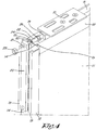
- the aforementioned first carriage 8 is mounted in the groove 14 of the top profile 13.
- a coupling 18 is mounted on this first carriage 8 for the said drive belt 7, as well as a lock plate 10 for the lock 9.
- the drive belt 7 is normally connected to the coupling 18 in the situation shown, but for the purpose of a better presentation of the invention it is not shown in figures 2 to 9 .
- the shape of the bottom part of the first carriage 8 is largely complementary to the shape of the groove 14 of the top profile 13.
- the first carriage is provided with a horizontal hole 19 with an internal screw thread.
- a second carriage 20 is affixed in the groove 14 of the side profile 12, which is located close to the top of this side profile 12.
- a horizontal passage 21 is made in this second carriage 20.
- the first carriage 8 and the second carriage 20 are coupled together by means of an adjusting rod 22 and a first nut 23.
- the adjusting rod 22 is provided over its entire length with an external screw thread that is complementary to the screw thread in the hole 19 of the first carriage 8.
- the adjusting rod 22 has a head 24 that is provided with a hexagonal recess 25 for a socket screw key.
- a thickening in this case in the form of a second nut 26 that is affixed to the adjusting rod 22 by means of the screw thread, and is fastened thereto, for example by welding or gluing.
- the end of the adjusting rod 22 turned away from the head 24 is screwed in the hole 19 of the first carriage 8.
- the other end, i.e. the end with the head 24, is inserted through the passage 21.
- the adjusting rod 22 is fastened to the second carriage 20, whereby the second carriage 20 is fastened between the first nut 23 and the second nut 26, so that the adjusting rod 22, and thus also the first carriage 8, is firmly secured.
- the first nut 23 is loosened somewhat, after which the adjusting rod 22 can be rotated from the side of the side profile 12 by means of a socket screw key that is inserted in the head 24 of the adjusting rod 22.
- the first carriage 8, the adjusting rod 22 and the second carriage 20 together form an adjustment mechanism in order to adjust the position of the lock plate 10 and to be able to fasten the lock plate 10 to the leaf 4.
- This action can be done while the leaf 4 is mounted in the frame 2, because for the adjustment only access to the first nut 23 and the head 24 of the adjusting rod 22 is required, whereby this access is possible from the side of the side profile 12.
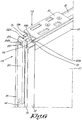
- the adjustable securing of the lock plate 10 can be done in this embodiment by further turning the two adjusting rods 22A, 22B in or out of the holes 19A, 19B in the first carriage 8 by means of a socket screw key.
- the second carriage 20 acts as an end stop for the heads 24A, 24B of the adjusting rods 22A, 22B.
- the first adjusting rod 22A is first turned further in a hole 19A, to enable the first carriage 8 to be pulled in the direction of the second carriage 20, after which the second adjusting rod 22B is turned further into a hole 19B to effectively pull the first carriage 8 to the second carriage 20 and to secure the first carriage 8.
- the second adjusting rod 22B is turned further out of a hole 19B to enable the first carriage 8 to be pushed away from the second carriage 20, after which the first adjusting rod 22A is turned out of its hole 19A to effectively push the first carriage 8 away from the second carriage 20 and to secure the first carriage 8.
- the invention is not limited to sliding windows 1 with a drive motor and leaves 4 for this purpose.
- lock plate 10 is described as a separate component screwed to the first carriage 8
- the lock plate 10 together with the first carriage 8 can also form one component, for example as a lock plate 10 with a base that is complementary to the shape of the groove 14.
Landscapes
- Engineering & Computer Science (AREA)
- Civil Engineering (AREA)
- Structural Engineering (AREA)
- Mechanical Engineering (AREA)
- Power-Operated Mechanisms For Wings (AREA)
- Wing Frames And Configurations (AREA)
Claims (14)
- Vantail (4) d'une fenêtre coulissante (1) ou d'une porte coulissante, dans lequel ce vantail (4) possède un profilé horizontal (13) et un profilé latéral vertical (12) perpendiculaire au profilé horizontal (13), dans lequel le profilé horizontal (13) est muni d'une plaque de verrouillage (10) pour un verrou (9), dans lequel le vantail (4) est équipé d'un mécanisme de réglage pour pouvoir régler la position de la plaque de verrouillage (10) dans la direction (P) dans laquelle s'étend le profilé horizontal (13) et pour pouvoir fixer la plaque de verrouillage (10) au vantail (4), dans lequel le mécanisme de réglage peut être actionné à partir du côté où se trouve le profilé latéral (12), caractérisé en ce que le profilé horizontal (13) est muni d'une première rainure (14) comportant des flancs (15) présentant des contre-dépouilles, qui s'étend dans la direction longitudinale du profilé horizontal (13), dans lequel un premier chariot (8) est maintenu dans la première rainure (14), dans lequel la plaque de verrouillage (10) fait partie du premier chariot (8) ou y est fixé.
- Vantail selon la revendication 1, caractérisé en ce que le profilé horizontal est un profilé supérieur ou inférieur du vantail à l'état monté.
- Vantail selon l'une quelconque des revendications précédentes, caractérisé en ce que le mécanisme de réglage comprend les composants suivants :- au moins un trou (19) dans la plaque de verrouillage (10) ou dans un composant fixe qui y est attaché, dans lequel ce trou (19) s'étend en direction horizontale et est muni d'un filet de vis interne ;- au moins une tige de réglage (22) qui est munie au moins en partie d'un filet de vis externe et qui est fixée dans le trou (19), dans lequel la tige de réglage (22) possède une tête (24) qui est conçue pour entrer en contact avec un outil pour la mise en rotation de la tige de réglage (22) et qui est orientée en direction du côté auquel est disposé le profilé latéral (12).
- Vantail selon la revendication 4, caractérisé en ce que ledit trou (19) est réalisé dans le premier chariot (8).
- Vantail selon la revendication 3 ou 4, caractérisé en ce que le mécanisme de réglage comprend également un élément de préhension qui, au moins dans la direction horizontale, possède une position fixe par rapport au profilé horizontal (13), dans lequel la tige de réglage (22) et l'élément de préhension sont conçus d'une manière telle que la tige de réglage (22) peut être fixée à l'élément de préhension, ou bien en ce que l'élément de préhension forme un arrêt terminal pour la tige de réglage (22).
- Vantail selon la revendication 5, caractérisé en ce que l'élément de préhension est formé par le profilé latéral (12) ou par un composant (20) qui y est fixé.
- Vantail selon la revendication 5 ou 6, caractérisé en ce que le profilé latéral (12) est muni d'une seconde rainure (14) comprenant des flancs (15) présentant des contre-dépouilles, qui s'étend dans la direction longitudinale du profilé latéral (12), dans lequel un second chariot (20) est maintenu dans la seconde rainure (14) et l'élément de préhension est formé par le second chariot (20).
- Vantail selon la revendication 7, caractérisé en ce que le second chariot (20) fait au moins en partie saillie par rapport au profilé latéral (12) dans la direction longitudinale du profilé latéral (12).
- Vantail selon l'une quelconque des revendications 5 à 8, caractérisé en ce que l'élément de préhension est muni d'un passage horizontal (21) et la tige de réglage (22) possède un épaississement (26) et un filet de vis est prévu entre la tête (24) et l'épaississement (26), dans lequel le passage (21) possède une dimension telle que la partie située entre la tête (24) et l'élargissement (26) vient s'insérer dans le passage (21), mais non l'élargissement (26).
- Vantail selon l'une quelconque des revendications 5 à 8, caractérisé en ce que le mécanisme de réglage comprend deux des trous susmentionnés (19A, 19B) et deux des tiges de réglage susmentionnées (22A, 22B), dans lequel l'élément de préhension est muni de deux passages horizontaux (21A, 21B), dans lequel une première combinaison d'un passage (21A) et d'une tige de réglage (22A) est telle que la tige de réglage (22A) n'est pas insérée à travers le passage (21A) et que la tête (24A) de la tige de réglage (22A) ne traverse pas le passage (21A), mais qu'un outil pour la mise en rotation de la tige de réglage (22A) traverse le passage (21A), et dans lequel une seconde combinaison d'un passage (21B) et d'une tige de réglage (22B) est telle que la tête (24B) de ladite réglage ne traverse pas le passage (21B) et que la tige de réglage (22B) est insérée à travers le passage (21B).
- Vantail selon l'une quelconque des revendications 3 à 10, caractérisé en ce que la tige de réglage (22) ou les tiges de réglage (22A, 22B) possède(nt) une tête (24, 24A, 24B) qui est munie d'un évidement (25) pour une clé de vis à tête creuse.
- Vantail selon l'une quelconque des revendications précédentes, caractérisé en ce que le profilé horizontal est un profilé supérieur (13).
- Fenêtre coulissante ou porte coulissante équipée d'un vantail selon l'une quelconque des revendications précédentes.
- Fenêtre coulissante ou porte coulissante selon la revendication 13, caractérisée en ce que le profilé horizontal est situé au sommet ou à la base du vantail, et le profilé latéral est vertical.
Applications Claiming Priority (2)
| Application Number | Priority Date | Filing Date | Title |
|---|---|---|---|
| BE2013/0566A BE1021702B1 (nl) | 2013-08-30 | 2013-08-30 | Vleugel van een schuifraam of schuifdeur en schuifraam of schuifdeur voorzien van een dergelijke vleugel |
| PCT/BE2014/000040 WO2015027301A1 (fr) | 2013-08-30 | 2014-08-21 | Vantail d'une fenêtre coulissante ou d'une porte coulissante et fenêtre coulissante ou porte coulissante comportant un tel vantail |
Publications (2)
| Publication Number | Publication Date |
|---|---|
| EP3039207A1 EP3039207A1 (fr) | 2016-07-06 |
| EP3039207B1 true EP3039207B1 (fr) | 2017-11-01 |
Family
ID=49447283
Family Applications (1)
| Application Number | Title | Priority Date | Filing Date |
|---|---|---|---|
| EP14776979.8A Active EP3039207B1 (fr) | 2013-08-30 | 2014-08-21 | Vantail d'une fenêtre coulissante ou d'une porte coulissante et fenêtre coulissante ou porte coulissante comportant un tel vantail |
Country Status (4)
| Country | Link |
|---|---|
| US (1) | US9890557B2 (fr) |
| EP (1) | EP3039207B1 (fr) |
| BE (1) | BE1021702B1 (fr) |
| WO (1) | WO2015027301A1 (fr) |
Families Citing this family (3)
| Publication number | Priority date | Publication date | Assignee | Title |
|---|---|---|---|---|
| US20190010754A1 (en) * | 2017-07-06 | 2019-01-10 | Charles Nystrom | Uplift Prevention Device |
| DE102021129219A1 (de) | 2021-11-10 | 2023-05-11 | Gretsch-Unitas GmbH Baubeschläge | Schiebeflügelanordnung |
| CN114622778B (zh) * | 2022-01-30 | 2022-11-01 | 山东正华建筑科技有限公司 | 智能电动控制平衡移动窗及其工作方法 |
Family Cites Families (13)
| Publication number | Priority date | Publication date | Assignee | Title |
|---|---|---|---|---|
| US3103713A (en) * | 1960-08-29 | 1963-09-17 | Amerock Corp | Sash lock |
| US3418016A (en) * | 1967-05-02 | 1968-12-24 | American Aluminum Window Corp | Sill lock for stationary panel of sliding glass door units |
| US3984136A (en) * | 1975-10-01 | 1976-10-05 | Bills Marius W | Lock for sliding doors |
| US4189870A (en) * | 1978-10-30 | 1980-02-26 | Helmick B J | Patio door roller assembly |
| US4304429A (en) * | 1980-01-28 | 1981-12-08 | Gist Marion A | Locking apparatus for sliding windows and the like |
| US5015022A (en) * | 1989-04-28 | 1991-05-14 | Mcguire Michael D | Chain lock for sliding door |
| GB2308404B (en) * | 1995-12-21 | 1999-09-29 | Plus Plan | Improvements relating to the security of doors and windows |
| US6321413B1 (en) * | 1999-06-10 | 2001-11-27 | Eku Ag | Running carriage for a sliding door |
| JP2001241272A (ja) * | 2000-02-29 | 2001-09-04 | Enomoto Co Ltd | 吊車型の引戸 |
| ES2338409T3 (es) * | 2002-09-06 | 2010-05-07 | Hawa Ag | Dispositivo de bloqueo para elemento de division. |
| US8752871B2 (en) * | 2011-07-21 | 2014-06-17 | Actron Manufacturing, Inc. | Wire strike assembly |
| US8881557B2 (en) * | 2012-01-14 | 2014-11-11 | Marc Franklin McEachern | Adjustable position blocking device for sliding closures |
| US9328543B2 (en) * | 2012-11-29 | 2016-05-03 | B/E Aerospace, Inc. | Galley cart bay door latch |
-
2013
- 2013-08-30 BE BE2013/0566A patent/BE1021702B1/nl active
-
2014
- 2014-08-21 EP EP14776979.8A patent/EP3039207B1/fr active Active
- 2014-08-21 WO PCT/BE2014/000040 patent/WO2015027301A1/fr not_active Ceased
- 2014-08-21 US US14/910,054 patent/US9890557B2/en active Active
Non-Patent Citations (1)
| Title |
|---|
| None * |
Also Published As
| Publication number | Publication date |
|---|---|
| BE1021702B1 (nl) | 2016-01-11 |
| EP3039207A1 (fr) | 2016-07-06 |
| US20160177595A1 (en) | 2016-06-23 |
| US9890557B2 (en) | 2018-02-13 |
| WO2015027301A1 (fr) | 2015-03-05 |
Similar Documents
| Publication | Publication Date | Title |
|---|---|---|
| US7987637B2 (en) | Adjustable shim | |
| US9167939B2 (en) | Shower door assembly | |
| US9410360B2 (en) | Door assembly | |
| US20160369547A1 (en) | Sliding-Door Closer Set | |
| US9890557B2 (en) | Leaf of a sliding window or sliding door and sliding window or sliding door provided with such a leaf | |
| US9187941B2 (en) | Roller assembly for sliding door | |
| CN110735573B (zh) | 一种多功能欧标u槽隐形铰链 | |
| CA2841281A1 (fr) | Ensemble de porte | |
| EP3061899A1 (fr) | Cadre de porte de douche et porte de douche | |
| US9909348B2 (en) | Leaf of a sliding window or sliding door | |
| DE102011056416A1 (de) | Anordnung einer Antriebseinheit einer Ausstell- oder Verriegelungseinrichtung | |
| EP3064112B1 (fr) | Dispositif de verrouillage et ensemble de salle de douche | |
| DE102008055794A1 (de) | Torsäule für Tore und Türen | |
| AU2014227553A1 (en) | Double hung window assembly | |
| US10512329B2 (en) | Anchoring group for wall cupboards with facilitated assembly | |
| EP3332915B1 (fr) | Outil de montage d'un opérateur pour portes battantes et portails motorisés | |
| EP1717404A2 (fr) | Bande d'étanchéité notamment pour portes et fenêtres | |
| AU2013270637B2 (en) | A window assembly | |
| JP6710632B2 (ja) | 建具 | |
| EP2806087B1 (fr) | Dispositif de fereture pour une fenêtre ou une porte | |
| KR102414296B1 (ko) | 여닫이창에 설치되는 방충망 창호 | |
| EP2886776A1 (fr) | Poste avant pour châssis muraux de portes coulissantes rétractables | |
| KR101994497B1 (ko) | 창호부재 변형 방지 장치 | |
| EP2829677A2 (fr) | Dispositif de retenue pour battants pivotants | |
| AU2013234401B2 (en) | A Friction Foot Assembly And Method Of Use Thereof |
Legal Events
| Date | Code | Title | Description |
|---|---|---|---|
| PUAI | Public reference made under article 153(3) epc to a published international application that has entered the european phase |
Free format text: ORIGINAL CODE: 0009012 |
|
| 17P | Request for examination filed |
Effective date: 20160119 |
|
| AK | Designated contracting states |
Kind code of ref document: A1 Designated state(s): AL AT BE BG CH CY CZ DE DK EE ES FI FR GB GR HR HU IE IS IT LI LT LU LV MC MK MT NL NO PL PT RO RS SE SI SK SM TR |
|
| AX | Request for extension of the european patent |
Extension state: BA ME |
|
| DAX | Request for extension of the european patent (deleted) | ||
| GRAP | Despatch of communication of intention to grant a patent |
Free format text: ORIGINAL CODE: EPIDOSNIGR1 |
|
| STAA | Information on the status of an ep patent application or granted ep patent |
Free format text: STATUS: GRANT OF PATENT IS INTENDED |
|
| INTG | Intention to grant announced |
Effective date: 20170710 |
|
| GRAS | Grant fee paid |
Free format text: ORIGINAL CODE: EPIDOSNIGR3 |
|
| GRAA | (expected) grant |
Free format text: ORIGINAL CODE: 0009210 |
|
| STAA | Information on the status of an ep patent application or granted ep patent |
Free format text: STATUS: THE PATENT HAS BEEN GRANTED |
|
| AK | Designated contracting states |
Kind code of ref document: B1 Designated state(s): AL AT BE BG CH CY CZ DE DK EE ES FI FR GB GR HR HU IE IS IT LI LT LU LV MC MK MT NL NO PL PT RO RS SE SI SK SM TR |
|
| REG | Reference to a national code |
Ref country code: GB Ref legal event code: FG4D |
|
| REG | Reference to a national code |
Ref country code: CH Ref legal event code: EP Ref country code: AT Ref legal event code: REF Ref document number: 942191 Country of ref document: AT Kind code of ref document: T Effective date: 20171115 |
|
| REG | Reference to a national code |
Ref country code: IE Ref legal event code: FG4D |
|
| REG | Reference to a national code |
Ref country code: CH Ref legal event code: NV Representative=s name: ORITI PATENTS - FRANCO ORITI, CH |
|
| REG | Reference to a national code |
Ref country code: DE Ref legal event code: R096 Ref document number: 602014016670 Country of ref document: DE |
|
| REG | Reference to a national code |
Ref country code: NL Ref legal event code: MP Effective date: 20171101 |
|
| REG | Reference to a national code |
Ref country code: LT Ref legal event code: MG4D |
|
| REG | Reference to a national code |
Ref country code: AT Ref legal event code: MK05 Ref document number: 942191 Country of ref document: AT Kind code of ref document: T Effective date: 20171101 |
|
| PG25 | Lapsed in a contracting state [announced via postgrant information from national office to epo] |
Ref country code: SE Free format text: LAPSE BECAUSE OF FAILURE TO SUBMIT A TRANSLATION OF THE DESCRIPTION OR TO PAY THE FEE WITHIN THE PRESCRIBED TIME-LIMIT Effective date: 20171101 Ref country code: NL Free format text: LAPSE BECAUSE OF FAILURE TO SUBMIT A TRANSLATION OF THE DESCRIPTION OR TO PAY THE FEE WITHIN THE PRESCRIBED TIME-LIMIT Effective date: 20171101 Ref country code: LT Free format text: LAPSE BECAUSE OF FAILURE TO SUBMIT A TRANSLATION OF THE DESCRIPTION OR TO PAY THE FEE WITHIN THE PRESCRIBED TIME-LIMIT Effective date: 20171101 Ref country code: ES Free format text: LAPSE BECAUSE OF FAILURE TO SUBMIT A TRANSLATION OF THE DESCRIPTION OR TO PAY THE FEE WITHIN THE PRESCRIBED TIME-LIMIT Effective date: 20171101 Ref country code: FI Free format text: LAPSE BECAUSE OF FAILURE TO SUBMIT A TRANSLATION OF THE DESCRIPTION OR TO PAY THE FEE WITHIN THE PRESCRIBED TIME-LIMIT Effective date: 20171101 Ref country code: NO Free format text: LAPSE BECAUSE OF FAILURE TO SUBMIT A TRANSLATION OF THE DESCRIPTION OR TO PAY THE FEE WITHIN THE PRESCRIBED TIME-LIMIT Effective date: 20180201 |
|
| PG25 | Lapsed in a contracting state [announced via postgrant information from national office to epo] |
Ref country code: AT Free format text: LAPSE BECAUSE OF FAILURE TO SUBMIT A TRANSLATION OF THE DESCRIPTION OR TO PAY THE FEE WITHIN THE PRESCRIBED TIME-LIMIT Effective date: 20171101 Ref country code: RS Free format text: LAPSE BECAUSE OF FAILURE TO SUBMIT A TRANSLATION OF THE DESCRIPTION OR TO PAY THE FEE WITHIN THE PRESCRIBED TIME-LIMIT Effective date: 20171101 Ref country code: HR Free format text: LAPSE BECAUSE OF FAILURE TO SUBMIT A TRANSLATION OF THE DESCRIPTION OR TO PAY THE FEE WITHIN THE PRESCRIBED TIME-LIMIT Effective date: 20171101 Ref country code: BG Free format text: LAPSE BECAUSE OF FAILURE TO SUBMIT A TRANSLATION OF THE DESCRIPTION OR TO PAY THE FEE WITHIN THE PRESCRIBED TIME-LIMIT Effective date: 20180201 Ref country code: IS Free format text: LAPSE BECAUSE OF FAILURE TO SUBMIT A TRANSLATION OF THE DESCRIPTION OR TO PAY THE FEE WITHIN THE PRESCRIBED TIME-LIMIT Effective date: 20180301 Ref country code: LV Free format text: LAPSE BECAUSE OF FAILURE TO SUBMIT A TRANSLATION OF THE DESCRIPTION OR TO PAY THE FEE WITHIN THE PRESCRIBED TIME-LIMIT Effective date: 20171101 Ref country code: GR Free format text: LAPSE BECAUSE OF FAILURE TO SUBMIT A TRANSLATION OF THE DESCRIPTION OR TO PAY THE FEE WITHIN THE PRESCRIBED TIME-LIMIT Effective date: 20180202 |
|
| PG25 | Lapsed in a contracting state [announced via postgrant information from national office to epo] |
Ref country code: EE Free format text: LAPSE BECAUSE OF FAILURE TO SUBMIT A TRANSLATION OF THE DESCRIPTION OR TO PAY THE FEE WITHIN THE PRESCRIBED TIME-LIMIT Effective date: 20171101 Ref country code: CY Free format text: LAPSE BECAUSE OF FAILURE TO SUBMIT A TRANSLATION OF THE DESCRIPTION OR TO PAY THE FEE WITHIN THE PRESCRIBED TIME-LIMIT Effective date: 20171101 Ref country code: DK Free format text: LAPSE BECAUSE OF FAILURE TO SUBMIT A TRANSLATION OF THE DESCRIPTION OR TO PAY THE FEE WITHIN THE PRESCRIBED TIME-LIMIT Effective date: 20171101 Ref country code: CZ Free format text: LAPSE BECAUSE OF FAILURE TO SUBMIT A TRANSLATION OF THE DESCRIPTION OR TO PAY THE FEE WITHIN THE PRESCRIBED TIME-LIMIT Effective date: 20171101 Ref country code: SK Free format text: LAPSE BECAUSE OF FAILURE TO SUBMIT A TRANSLATION OF THE DESCRIPTION OR TO PAY THE FEE WITHIN THE PRESCRIBED TIME-LIMIT Effective date: 20171101 |
|
| REG | Reference to a national code |
Ref country code: FR Ref legal event code: PLFP Year of fee payment: 5 |
|
| REG | Reference to a national code |
Ref country code: DE Ref legal event code: R097 Ref document number: 602014016670 Country of ref document: DE |
|
| PG25 | Lapsed in a contracting state [announced via postgrant information from national office to epo] |
Ref country code: SM Free format text: LAPSE BECAUSE OF FAILURE TO SUBMIT A TRANSLATION OF THE DESCRIPTION OR TO PAY THE FEE WITHIN THE PRESCRIBED TIME-LIMIT Effective date: 20171101 Ref country code: RO Free format text: LAPSE BECAUSE OF FAILURE TO SUBMIT A TRANSLATION OF THE DESCRIPTION OR TO PAY THE FEE WITHIN THE PRESCRIBED TIME-LIMIT Effective date: 20171101 Ref country code: IT Free format text: LAPSE BECAUSE OF FAILURE TO SUBMIT A TRANSLATION OF THE DESCRIPTION OR TO PAY THE FEE WITHIN THE PRESCRIBED TIME-LIMIT Effective date: 20171101 Ref country code: PL Free format text: LAPSE BECAUSE OF FAILURE TO SUBMIT A TRANSLATION OF THE DESCRIPTION OR TO PAY THE FEE WITHIN THE PRESCRIBED TIME-LIMIT Effective date: 20171101 |
|
| PLBE | No opposition filed within time limit |
Free format text: ORIGINAL CODE: 0009261 |
|
| STAA | Information on the status of an ep patent application or granted ep patent |
Free format text: STATUS: NO OPPOSITION FILED WITHIN TIME LIMIT |
|
| 26N | No opposition filed |
Effective date: 20180802 |
|
| PG25 | Lapsed in a contracting state [announced via postgrant information from national office to epo] |
Ref country code: SI Free format text: LAPSE BECAUSE OF FAILURE TO SUBMIT A TRANSLATION OF THE DESCRIPTION OR TO PAY THE FEE WITHIN THE PRESCRIBED TIME-LIMIT Effective date: 20171101 |
|
| PG25 | Lapsed in a contracting state [announced via postgrant information from national office to epo] |
Ref country code: MT Free format text: LAPSE BECAUSE OF NON-PAYMENT OF DUE FEES Effective date: 20180821 |
|
| PG25 | Lapsed in a contracting state [announced via postgrant information from national office to epo] |
Ref country code: TR Free format text: LAPSE BECAUSE OF FAILURE TO SUBMIT A TRANSLATION OF THE DESCRIPTION OR TO PAY THE FEE WITHIN THE PRESCRIBED TIME-LIMIT Effective date: 20171101 |
|
| PG25 | Lapsed in a contracting state [announced via postgrant information from national office to epo] |
Ref country code: PT Free format text: LAPSE BECAUSE OF FAILURE TO SUBMIT A TRANSLATION OF THE DESCRIPTION OR TO PAY THE FEE WITHIN THE PRESCRIBED TIME-LIMIT Effective date: 20171101 |
|
| PG25 | Lapsed in a contracting state [announced via postgrant information from national office to epo] |
Ref country code: MK Free format text: LAPSE BECAUSE OF NON-PAYMENT OF DUE FEES Effective date: 20171101 Ref country code: HU Free format text: LAPSE BECAUSE OF FAILURE TO SUBMIT A TRANSLATION OF THE DESCRIPTION OR TO PAY THE FEE WITHIN THE PRESCRIBED TIME-LIMIT; INVALID AB INITIO Effective date: 20140821 |
|
| PG25 | Lapsed in a contracting state [announced via postgrant information from national office to epo] |
Ref country code: AL Free format text: LAPSE BECAUSE OF FAILURE TO SUBMIT A TRANSLATION OF THE DESCRIPTION OR TO PAY THE FEE WITHIN THE PRESCRIBED TIME-LIMIT Effective date: 20171101 |
|
| P01 | Opt-out of the competence of the unified patent court (upc) registered |
Effective date: 20230418 |
|
| PGFP | Annual fee paid to national office [announced via postgrant information from national office to epo] |
Ref country code: LU Payment date: 20250820 Year of fee payment: 12 |
|
| PGFP | Annual fee paid to national office [announced via postgrant information from national office to epo] |
Ref country code: DE Payment date: 20250819 Year of fee payment: 12 |
|
| PGFP | Annual fee paid to national office [announced via postgrant information from national office to epo] |
Ref country code: MC Payment date: 20250820 Year of fee payment: 12 |
|
| PGFP | Annual fee paid to national office [announced via postgrant information from national office to epo] |
Ref country code: BE Payment date: 20250820 Year of fee payment: 12 Ref country code: GB Payment date: 20250818 Year of fee payment: 12 |
|
| PGFP | Annual fee paid to national office [announced via postgrant information from national office to epo] |
Ref country code: FR Payment date: 20250821 Year of fee payment: 12 |
|
| PGFP | Annual fee paid to national office [announced via postgrant information from national office to epo] |
Ref country code: CH Payment date: 20250901 Year of fee payment: 12 |
|
| PGFP | Annual fee paid to national office [announced via postgrant information from national office to epo] |
Ref country code: IE Payment date: 20250821 Year of fee payment: 12 |