EP3039743B1 - Feststoffbatterie mit verbessertem temperaturmanagement - Google Patents
Feststoffbatterie mit verbessertem temperaturmanagement Download PDFInfo
- Publication number
- EP3039743B1 EP3039743B1 EP14841310.7A EP14841310A EP3039743B1 EP 3039743 B1 EP3039743 B1 EP 3039743B1 EP 14841310 A EP14841310 A EP 14841310A EP 3039743 B1 EP3039743 B1 EP 3039743B1
- Authority
- EP
- European Patent Office
- Prior art keywords
- thermal control
- cathode
- control wire
- solid
- anode
- Prior art date
- Legal status (The legal status is an assumption and is not a legal conclusion. Google has not performed a legal analysis and makes no representation as to the accuracy of the status listed.)
- Not-in-force
Links
Images


Classifications
-
- H—ELECTRICITY
- H01—ELECTRIC ELEMENTS
- H01M—PROCESSES OR MEANS, e.g. BATTERIES, FOR THE DIRECT CONVERSION OF CHEMICAL ENERGY INTO ELECTRICAL ENERGY
- H01M10/00—Secondary cells; Manufacture thereof
- H01M10/60—Heating or cooling; Temperature control
- H01M10/65—Means for temperature control structurally associated with the cells
- H01M10/654—Means for temperature control structurally associated with the cells located inside the innermost case of the cells, e.g. mandrels, electrodes or electrolytes
-
- H—ELECTRICITY
- H01—ELECTRIC ELEMENTS
- H01M—PROCESSES OR MEANS, e.g. BATTERIES, FOR THE DIRECT CONVERSION OF CHEMICAL ENERGY INTO ELECTRICAL ENERGY
- H01M10/00—Secondary cells; Manufacture thereof
- H01M10/05—Accumulators with non-aqueous electrolyte
- H01M10/052—Li-accumulators
-
- H—ELECTRICITY
- H01—ELECTRIC ELEMENTS
- H01M—PROCESSES OR MEANS, e.g. BATTERIES, FOR THE DIRECT CONVERSION OF CHEMICAL ENERGY INTO ELECTRICAL ENERGY
- H01M10/00—Secondary cells; Manufacture thereof
- H01M10/05—Accumulators with non-aqueous electrolyte
- H01M10/056—Accumulators with non-aqueous electrolyte characterised by the materials used as electrolytes, e.g. mixed inorganic/organic electrolytes
- H01M10/0561—Accumulators with non-aqueous electrolyte characterised by the materials used as electrolytes, e.g. mixed inorganic/organic electrolytes the electrolyte being constituted of inorganic materials only
- H01M10/0562—Solid materials
-
- H—ELECTRICITY
- H01—ELECTRIC ELEMENTS
- H01M—PROCESSES OR MEANS, e.g. BATTERIES, FOR THE DIRECT CONVERSION OF CHEMICAL ENERGY INTO ELECTRICAL ENERGY
- H01M10/00—Secondary cells; Manufacture thereof
- H01M10/05—Accumulators with non-aqueous electrolyte
- H01M10/058—Construction or manufacture
- H01M10/0585—Construction or manufacture of accumulators having only flat construction elements, i.e. flat positive electrodes, flat negative electrodes and flat separators
-
- H—ELECTRICITY
- H01—ELECTRIC ELEMENTS
- H01M—PROCESSES OR MEANS, e.g. BATTERIES, FOR THE DIRECT CONVERSION OF CHEMICAL ENERGY INTO ELECTRICAL ENERGY
- H01M10/00—Secondary cells; Manufacture thereof
- H01M10/60—Heating or cooling; Temperature control
- H01M10/61—Types of temperature control
- H01M10/613—Cooling or keeping cold
-
- H—ELECTRICITY
- H01—ELECTRIC ELEMENTS
- H01M—PROCESSES OR MEANS, e.g. BATTERIES, FOR THE DIRECT CONVERSION OF CHEMICAL ENERGY INTO ELECTRICAL ENERGY
- H01M10/00—Secondary cells; Manufacture thereof
- H01M10/60—Heating or cooling; Temperature control
- H01M10/61—Types of temperature control
- H01M10/615—Heating or keeping warm
-
- H—ELECTRICITY
- H01—ELECTRIC ELEMENTS
- H01M—PROCESSES OR MEANS, e.g. BATTERIES, FOR THE DIRECT CONVERSION OF CHEMICAL ENERGY INTO ELECTRICAL ENERGY
- H01M10/00—Secondary cells; Manufacture thereof
- H01M10/60—Heating or cooling; Temperature control
- H01M10/65—Means for temperature control structurally associated with the cells
- H01M10/657—Means for temperature control structurally associated with the cells by electric or electromagnetic means
- H01M10/6571—Resistive heaters
-
- H—ELECTRICITY
- H01—ELECTRIC ELEMENTS
- H01M—PROCESSES OR MEANS, e.g. BATTERIES, FOR THE DIRECT CONVERSION OF CHEMICAL ENERGY INTO ELECTRICAL ENERGY
- H01M10/00—Secondary cells; Manufacture thereof
- H01M10/60—Heating or cooling; Temperature control
- H01M10/65—Means for temperature control structurally associated with the cells
- H01M10/657—Means for temperature control structurally associated with the cells by electric or electromagnetic means
- H01M10/6572—Peltier elements or thermoelectric devices
-
- H—ELECTRICITY
- H01—ELECTRIC ELEMENTS
- H01M—PROCESSES OR MEANS, e.g. BATTERIES, FOR THE DIRECT CONVERSION OF CHEMICAL ENERGY INTO ELECTRICAL ENERGY
- H01M4/00—Electrodes
- H01M4/02—Electrodes composed of, or comprising, active material
- H01M4/64—Carriers or collectors
-
- H—ELECTRICITY
- H01—ELECTRIC ELEMENTS
- H01M—PROCESSES OR MEANS, e.g. BATTERIES, FOR THE DIRECT CONVERSION OF CHEMICAL ENERGY INTO ELECTRICAL ENERGY
- H01M4/00—Electrodes
- H01M4/02—Electrodes composed of, or comprising, active material
- H01M4/64—Carriers or collectors
- H01M4/70—Carriers or collectors characterised by shape or form
- H01M4/75—Wires, rods or strips
-
- H—ELECTRICITY
- H01—ELECTRIC ELEMENTS
- H01M—PROCESSES OR MEANS, e.g. BATTERIES, FOR THE DIRECT CONVERSION OF CHEMICAL ENERGY INTO ELECTRICAL ENERGY
- H01M50/00—Constructional details or processes of manufacture of the non-active parts of electrochemical cells other than fuel cells, e.g. hybrid cells
- H01M50/40—Separators; Membranes; Diaphragms; Spacing elements inside cells
-
- H—ELECTRICITY
- H01—ELECTRIC ELEMENTS
- H01M—PROCESSES OR MEANS, e.g. BATTERIES, FOR THE DIRECT CONVERSION OF CHEMICAL ENERGY INTO ELECTRICAL ENERGY
- H01M50/00—Constructional details or processes of manufacture of the non-active parts of electrochemical cells other than fuel cells, e.g. hybrid cells
- H01M50/40—Separators; Membranes; Diaphragms; Spacing elements inside cells
- H01M50/489—Separators, membranes, diaphragms or spacing elements inside the cells, characterised by their physical properties, e.g. swelling degree, hydrophilicity or shut down properties
- H01M50/497—Ionic conductivity
-
- H—ELECTRICITY
- H01—ELECTRIC ELEMENTS
- H01M—PROCESSES OR MEANS, e.g. BATTERIES, FOR THE DIRECT CONVERSION OF CHEMICAL ENERGY INTO ELECTRICAL ENERGY
- H01M10/00—Secondary cells; Manufacture thereof
- H01M10/60—Heating or cooling; Temperature control
- H01M10/63—Control systems
- H01M10/637—Control systems characterised by the use of reversible temperature-sensitive devices, e.g. NTC, PTC or bimetal devices; characterised by control of the internal current flowing through the cells, e.g. by switching
-
- H—ELECTRICITY
- H01—ELECTRIC ELEMENTS
- H01M—PROCESSES OR MEANS, e.g. BATTERIES, FOR THE DIRECT CONVERSION OF CHEMICAL ENERGY INTO ELECTRICAL ENERGY
- H01M10/00—Secondary cells; Manufacture thereof
- H01M10/42—Methods or arrangements for servicing or maintenance of secondary cells or secondary half-cells
- H01M10/425—Structural combination with electronic components, e.g. electronic circuits integrated to the outside of the casing
- H01M2010/4271—Battery management systems including electronic circuits, e.g. control of current or voltage to keep battery in healthy state, cell balancing
-
- Y—GENERAL TAGGING OF NEW TECHNOLOGICAL DEVELOPMENTS; GENERAL TAGGING OF CROSS-SECTIONAL TECHNOLOGIES SPANNING OVER SEVERAL SECTIONS OF THE IPC; TECHNICAL SUBJECTS COVERED BY FORMER USPC CROSS-REFERENCE ART COLLECTIONS [XRACs] AND DIGESTS
- Y02—TECHNOLOGIES OR APPLICATIONS FOR MITIGATION OR ADAPTATION AGAINST CLIMATE CHANGE
- Y02E—REDUCTION OF GREENHOUSE GAS [GHG] EMISSIONS, RELATED TO ENERGY GENERATION, TRANSMISSION OR DISTRIBUTION
- Y02E60/00—Enabling technologies; Technologies with a potential or indirect contribution to GHG emissions mitigation
- Y02E60/10—Energy storage using batteries
-
- Y—GENERAL TAGGING OF NEW TECHNOLOGICAL DEVELOPMENTS; GENERAL TAGGING OF CROSS-SECTIONAL TECHNOLOGIES SPANNING OVER SEVERAL SECTIONS OF THE IPC; TECHNICAL SUBJECTS COVERED BY FORMER USPC CROSS-REFERENCE ART COLLECTIONS [XRACs] AND DIGESTS
- Y02—TECHNOLOGIES OR APPLICATIONS FOR MITIGATION OR ADAPTATION AGAINST CLIMATE CHANGE
- Y02P—CLIMATE CHANGE MITIGATION TECHNOLOGIES IN THE PRODUCTION OR PROCESSING OF GOODS
- Y02P70/00—Climate change mitigation technologies in the production process for final industrial or consumer products
- Y02P70/50—Manufacturing or production processes characterised by the final manufactured product
Definitions
- the present disclosure relates to batteries and more particularly to solid state batteries.
- JP 2004 063397 A discloses a battery having positive and negative electrode terminals and a temperature sensor that measures the temperature of a battery main body.
- US 2008/268333 A1 discloses an electrochemical battery having at least one self contained thermoelectric cooling device such as a Peltier device, for cooling the battery to optimal operating conditions.
- JP2004127744A discloses a thermoelectric element which is directly laminated on a positive electrode current collector or a negative electrode current collector of the secondary battery, and has a structure of charging the second battery by the electromotive force of the thermoelectric element utilizing the heat generated by the secondary battery.
- US20120285758A1 relates to battery thermal management systems and thermoelectric cooling and heating batteries.
- Li-ion batteries are attractive energy storage systems for portable electronics and electric and hybrid-electric vehicles because of their high specific energy compared to other electrochemical energy storage devices.
- batteries with a form of lithium metal incorporated into the negative electrode afford exceptionally high specific energy (measured in Wh/kg) and energy density (measured in Wh/L) compared to batteries with conventional carbonaceous negative electrodes.
- lithium-intercalating oxides e.g., LiCoO 2 , LiNi 0.8 Co 0.15 Al 0.05 O 2 , and Li 1.1 Ni 0.3 Co 0.3 Mn 0.3 O 2
- LiCoO 2 , LiNi 0.8 Co 0.15 Al 0.05 O 2 , and Li 1.1 Ni 0.3 Co 0.3 Mn 0.3 O 2 are typically limited to a theoretical capacity of ⁇ 280 mAh/g (based on the mass of the lithiated oxide) and a practical capacity of 180 to 250 mAh/g.
- the specific capacity of lithium metal is about 3863 mAh/g.
- the highest theoretical capacity achievable for a lithium-ion positive electrode is 1168 mAh/g (based on the mass of the lithiated material), which is shared by Li 2 S and Li 2 O 2 .
- Other high-capacity materials including BiF 3 (303 mAh/g, lithiated) and FeF 3 (712 mAh/g, lithiated) are identified in Amatucci, G.G. and N. Pereira, Fluoride based electrode materials for advanced energy storage devices. Journal of Fluorine Chemistry, 2007. 128(4): p. 243-262 . All of the foregoing materials, however, react with lithium at a lower voltage compared to conventional oxide positive electrodes, hence limiting the theoretical specific energy. The theoretical specific energies of the foregoing materials, however, are very high (> 800 Wh/kg, compared to a maximum of ⁇ 500 Wh/kg for a cell with lithium negative and conventional oxide positive electrodes).
- Li metal negative electrode (sometimes referred to as an anode) is the much higher energy density of the entire cell, as compared to cells with graphitic or other intercalation negative electrodes.
- a disadvantage of using pure Li metal is that lithium is highly reactive. Accordingly, the lithium metal has a propensity to undergo morphology changes, which cause structures having a high surface area to form on and around the negative electrode when the cell is being charged. Exemplary high surface area structures include dendrites and mossy structures.
- Dendrites are the most common failure mode for cells with Li metal anodes.
- the dendrites form with a needle-like structure and can grow through the separator during charging of the cell, resulting in an internal short.
- "Soft shorts” that burn out rapidly result in a temporary self-discharge of the cell, while “strong shorts” consisting of a higher, more stable contact area can lead to complete discharge of the cell, cell failure, and even thermal runaway.
- dendrites typically grow through the separator during charge, shorts can also develop during discharge depending on the external pressure placed on the cell and/or internal volume changes that occur in both the negative and positive electrodes.
- Li metal is highly electronically conductive
- the surface of the Li tends to roughen as the metal is plated and stripped. Peaks in the surface grow as dendrites during charge. During discharge, some smoothing of the dendrites occurs. Nonetheless, there is typically some roughness that remains at the end of discharge. Depending on the depth of discharge, the overall roughness can be amplified from one cycle to the next. Because the metal is essentially at the same electrochemical potential throughout, potential and, to a lesser extent, concentration gradients in the electrolyte phase drive the change in morphology.
- Li morphology which tends to increase the electrode surface area with cycling and consumes solvent to generate fresh passivation layers.
- Formation of high-surface-area mossy Li tends to occur during low-rate deposition from a liquid electrolyte, especially if the salt concentration is high.
- the high surface area combined with high reactivity of Li and flammability of the organic solvent makes for a very reactive and dangerous cell.
- Li metal interfacial resistance Another significant challenge in realizing a commercially viable battery incorporating a Li metal anode is the high Li metal interfacial resistance, and the slow transport of Li in the materials typically present in a solid state cell containing Li metal, as well as kinetics of Li transfer between phases on the cathode side of the cell.
- typical solid state electrolyte materials have maximum ionic conductivities at room temperature of up to 10 -3 S/cm. This is insufficient for power demanding applications such as those which require ionic conductivities greater than 10 -2 S/cm.
- the invention provides a solid-state battery system as recited in claim 1 and a method of forming a solid-state battery system as recited in claim 5.
- Advantageous embodiments are set out in the dependent claims.
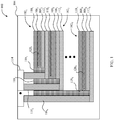
- FIG. 1 depicts an electrochemical battery 100.
- the electrochemical battery 100 includes a number of cells or cell stacks 102 X within a packaging 104 or other surrounding environment that is both electrically insulating and (optionally) thermally conductive.
- the packaging 104 improves the safety of the electrochemical battery 100.
- the operating voltage of the battery 100 can be modified to the desired voltage.
- each cell 102 X has an operating voltage of ⁇ 4 V
- 100 cells 102 X can be stacked to produce a device that has an operating voltage of ⁇ 400 V.
- a given power can be achieved while passing a low current through each of the cells 102 X . Therefore, wiring of the cells 102 X can be achieved with small-diameter electrical conductors while maintaining high energy efficiency.
- the battery 100 thus provides an operating voltage greater than 5 V, and in some embodiments, greater than 50 V.
- Each of the cells 102 X includes an anode 106 X , a separator 108 X , and a cathode 110 X .
- a base layer 112 X which is typically metal such as copper and can serve as a current collector as well as a feedthrough to an integrated circuit or multiplexor 114, is positioned adjacent to the anode 106 X and between the anode 106 X and an adjacent cathode.
- the base layer 112 1 is located between the anode 106 1 and the cathode 110 2 .
- the multiplexor 114 is depicted within the packaging 104, in some embodiments the multiplexor 114 is provided external to the packaging 104.
- the multiplexer 114 may be a solid-state device with insulating material between the electronic leads 116 X which connect the multiplexor 114 to the base layers 112 X .
- the leads 116 X of the multiplexer 114 which contact each terminal of the cell stack may extend to the top of the cell to an electrical circuit used for monitoring and controlling the current through each of the leads.
- Insulators 118 X are located between the leads 116 X and the ends of the anodes 106 X , separators 108 X , and cathodes 110 X .
- the anodes 106 X include Li metal or some other Li-insertion material that can reversibly insert and extract Li ions electrochemically.
- the anodes 106 X are sized such that they have at least as much capacity as the associated cathode 110 X , and preferably at least 10% excess capacity and up to greater than 50% capacity in some embodiments.
- the cathodes 110 X in various embodiments include a sulfur or sulfur-containing material (e.g., PAN-S composite or Li 2 S); an air electrode or Li 2 O 2 containing electrode; Li-insertion materials such as NCM, LiNi 0.5 Mn 1.5 O 4 , Li-rich layered oxides, LiCoO 2 , LiFePO 4 , LiMn 2 O 4 ; Li-rich NCM, NCA, and other Li intercalation materials, or blends thereof or any other active material or blend of materials that react with and/or insert Li cations and/or electrolyte anions.
- the cathodes 110 X may be fully dense.
- the cathodes 110 X may include Li-conducting polymer, ceramic or other solid, non-polymer electrolyte.
- the cathode Li-insertion materials may additionally be coated (e.g., via spray coating) with a material such as LiNbO 3 in order to improve the flow of ions between the Li-insertion materials and the solid electrolyte, as described in T. Ohtomo et al., Journal of Power Sources 233 (2013) 231-235 .
- Solid electrolyte materials in the cathodes 110 X may further include lithium conducting garnets, lithium conducting sulfides (e.g., Li 2 S-P 2 S 5 ) or phosphates, Li 3 P, LIPON, Li-conducting polymer (e.g., PEO), Li-conducting metal-organic frameworks such as described by Wiers et al.
- lithium conducting garnets lithium conducting sulfides (e.g., Li 2 S-P 2 S 5 ) or phosphates, Li 3 P, LIPON, Li-conducting polymer (e.g., PEO), Li-conducting metal-organic frameworks such as described by Wiers et al.
- cathodes 110 X may include Li 7-x La 3 Ta x Zr 2-x O 12 , wherein 0 ⁇ X ⁇ 2, electronically conductive additives such as carbon black, and a binder material.
- the cathode materials are selected to allow sufficient electrolyte-cathode interfacial area for a desired design.
- the separators 108 X are a Li-conducting solid electrolyte which are electronically insulating.
- the separators 108 X include thermal control wires 120 X .
- the thermal control wires 120 X are substantially the same, and are discussed in further reference to the thermal control wire 120 1 shown in FIGs. 2-3 .
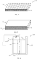
- the thermal control wire 120 1 is a sinusoidal wire which is embedded within the material 122 1 used to form the separator 108 1 .
- the thermal control wire 120 1 in some examples not part of the invention is a resistive wire laminated or sintered in the electrolyte bulk material 122 1 .
- the Li-ions flow through the bulk material 122 1 and pass the thermal control wire 120 1 in vertical direction in the orientation of FIG. 2 . Due to the low thickness of the thermal control wire 120 1 (on the order of microns) the available ion conducting area/volume of the electrolyte is sufficient for unimpeded transport.
- the thermal control wire is a thermoelectric material to allow a cooling option.
- FIG. 4 depicts a separator 130 with thermal control wires 132 in the form of thermoelectric material within channels in an electrolyte material 134. Thermoelectric ceramics can be sintered and included in channels through the electrolyte 134.
- FIG. 5 depicts an alternative embodiment which includes thermoelectric thermal control wires 142 at the interface between a layer 140 and another layer 144.
- the thermal control wires are positioned between one or more of the anode and the anode current collector, and the cathode and the cathode current collector, the cathode and the separator, and the anode and the separator, in addition to or as an alternative to positioning a thermal control wire in the separator.
- Thermoelectric materials in different embodiments include Bi 2 Te 3 , Bi 2 Se 3 , PbTe, PbTe 1-x Se x , Mg 2 Si, Mg 2 Sn, Mg 2 Ge.
- the thermal control wires 132/142 allow local heating or cooling of a specific cell volume due to the thermoelectric effect that generates a heat flow in a defined direction depending on the electronic current direction through the material.
- the thermoelectric material can be used to heat the internal ion transporting parts (electrode and electrolyte) of the cell while the current collector can be cooled at the same time. This means ionic transport is significantly improved because ionic conductivity increases with higher temperature. At the same time the current collector is cooled, because the thermoelectric transports heat to the inside of the cell.
- the electronic conductivity of the metallic current collector is also improved because the temperature dependence of the electronic conductivity in metals is just opposite to the behavior of ionic conductors.
- the current collectors can be designed at a smaller thickness but can still carry enough current for high rate capability.
- thermoelectric wire By reversing the current direction through the thermoelectric wire, the heat flow can be reversed and the internal layers of the cell are cooled while the current collectors act as heat sinks. Thus a solid thin-film electrolyte (thickness of about several 10 microns) is cooled rapidly and its ionic conductivity is dramatically lowered. In some embodiments, this feature/operation mode is used to shut down the cell in case of a sensed failure.
- FIG. 6 depicts one embodiment of powering a thermal control (being a thermoelectric material).
- a cell 150 includes an anode 152, a cathode 154, and a separator 156.
- a current collector 158 is provided for the anode 152 while a current collector 160 is provided for the cathode 154.
- a thermal control wire 162 which is a thermoelectric material is provided within the separator 156.
- One end of the thermal control wire 162 is connected to the cathode current collector 160 while the other end of the thermal control wire 162 is connected to the anode current collector 158 through a variable resistive load 164.
- the variable resistive load 164 is controlled by a battery management system (BMS) 166.
- the BMS includes a memory having program instructions stored therein and a processor operably connected to the memory and configured to execute the program instructions to control the resistive load 164 to effect a desired temperature in one or more of the components of the battery 100.
- the thermal control wire 162 is not controlled by a BMS.
- one lead of the thermal control wire 162 is connected to the cathode or the anode while the other lead is connected through the external circuit back to the anode or cathode respectively. This means the current through the thermal control wire 162 is proportional to the current through the battery and the system is intimately coupled.
- FIG. 7 depicts a cell 170 includes an anode 172, a cathode 174, and a separator 176.
- a current collector 178 is provided for the anode 172 while a current collector 180 is provided for the cathode 174.
- a thermal control wire 182 which is a thermoelectric material is provided within the separator 176.
- the anode current collector 178 and the cathode current collector 180 are connected to an external load 184 while the thermal control wire is operably connected to a BMS 186.
- the BMS drives or controls the magnitude and direction of current through the wire or thermoelectric material and controls depending on the desired operation mode of the battery.
- the above described embodiments provide thermal control wires that allow local modification of the temperature of a solid electrolyte and hence increase its conductivity when needed for more power demanding operation modes of the battery system.
- the thermal control wires can be controlled by the battery management system (BMS) and be directly powered by the battery system or by a separate external energy source.
- BMS battery management system
- a thermoelectric conductor that can redistribute heat within a solid state cell, stack or pack is provided in order to increase the local temperature of ionic conductors (increases ionic conductivity) and simultaneously cool the metallic current collectors and other electronic conductors (cooling decreases electronic resistance).
- the above described embodiments exhibit much lower energy consumption than heating a complete stack or pack with large heat capacity.
- the described embodiments provide quick response of the system, because only a thin electrolyte layer (low heat capacity) has to be heated.
- the described embodiments have a low impact on the chemistries of cathode and anode, because they are not affected by an overall increased system temperature.
- a BMS can be used to provide simple control of the embodiments.
- the resistive heater R
- the described embodiments can provide a cooling feature (e. g. for emergency shutdown of the battery by freezing the ions) by integration of thermoelectric materials.
- the direction of current through the thermoelectric wire determines whether a certain area within the cell is heated or cooled.
Landscapes
- Chemical & Material Sciences (AREA)
- Chemical Kinetics & Catalysis (AREA)
- Electrochemistry (AREA)
- General Chemical & Material Sciences (AREA)
- Engineering & Computer Science (AREA)
- Manufacturing & Machinery (AREA)
- Physics & Mathematics (AREA)
- Electromagnetism (AREA)
- Condensed Matter Physics & Semiconductors (AREA)
- General Physics & Mathematics (AREA)
- Inorganic Chemistry (AREA)
- Secondary Cells (AREA)
- Automation & Control Theory (AREA)
- Battery Electrode And Active Subsutance (AREA)
Claims (8)
- Festkörperbatteriesystem, umfassend:eine erste Anode (106; 172);eine erste Kathode (110; 174);eine variable resistive Last (164);eine erste Festkörperelektrolytschicht (108; 134; 156; 176), die zwischen der ersten Anode (106; 172) und der ersten Kathode (110; 174) positioniert ist;ein Gehäuse (104), das die erste Anode (106; 172), die erste Kathode (110; 174) und die erste Festkörperelektrolytschicht (108; 134; 156; 176) umschließt;mindestens einen Wärmesteuerdraht (120; 132; 142; 162; 182), der innerhalb der ersten Festkörperelektrolytschicht (108; 134; 156; 176) positioniert ist, wobei der mindestens eine Wärmesteuerdraht (120; 132; 142; 162; 182) ein thermoelektrisches Material umfasst, sich über die variable resistive Last (164) in elektrischer Kommunikation mit der ersten Anode (106; 172) befindet, sich in elektrischer Kommunikation mit der ersten Kathode (110; 174) befindet und dazu konfiguriert ist, eine Temperatur innerhalb des Gehäuses (104) zu modifizieren; undein Batterieverwaltungssystem (166), das dazu konfiguriert ist, die variable resistive Last (164) zu steuern, um eine Temperatur in der ersten Festkörperelektrolytschicht (108; 134; 156; 176) zu modifizieren, einen Ausfall der Zelle zu identifizieren und die erste Festkörperelektrolytschicht (108; 134; 156; 176) unter Verwendung des mindestens einen Wärmesteuerdrahts (120; 132; 142; 162; 182) als Reaktion auf den identifizierten Ausfall zu kühlen.
- Batteriesystem nach Anspruch 1, ferner umfassend: einen ersten Stromkollektor (180), der funktionsfähig mit der ersten Kathode (110; 174) verbunden ist, wobei der mindestens eine Wärmesteuerdraht (120; 132; 142; 162; 182) an einer Grenzfläche des ersten Stromkollektors (180) und der ersten Kathode (110; 174) positioniert ist.
- Batteriesystem nach Anspruch 2, ferner umfassend: einen zweiten Stromkollektor (178), der funktionsfähig mit der ersten Anode (106; 172) verbunden ist, wobei der mindestens eine Wärmesteuerdraht (120; 132; 142; 162; 182) an einer Grenzfläche des zweiten Stromkollektors (178) und der ersten Anode (106; 172) positioniert ist.
- Batteriesystem nach Anspruch 1, ferner umfassend: eine zweite Anode (106; 172) innerhalb des Gehäuses (104) und von der ersten Kathode (110; 174) um eine Basisschicht (112) beabstandet;
eine zweite Kathode (110; 174); und
eine zweite Festkörperelektrolytschicht (108; 134; 156; 176), die zwischen der zweiten Anode (106; 172) und der zweiten Kathode (110; 174) positioniert ist, wobei sich der mindestens eine Wärmesteuerdraht (120; 132; 142; 162; 182) innerhalb der zweiten Festkörperelektrolytschicht (108; 134; 156; 176) befindet. - Verfahren zum Bilden eines Festkörperbatteriesystems, umfassend:Bereitstellen einer ersten Anode (106; 172) innerhalb eines Gehäuses (104);Bereitstellen einer ersten Kathode (110; 174) innerhalb des Gehäuses (104);Positionieren einer ersten Festkörperelektrolytschicht (108; 134; 156; 176) innerhalb des Gehäuses (104) zwischen der ersten Anode (106; 172) und der ersten Kathode (110; 174);Positionieren von mindestens einem Wärmesteuerdraht (120; 132; 142; 162; 182), der ein thermoelektrisches Material umfasst, innerhalb der ersten Festkörperelektrolytschicht (108; 134; 156; 176), was Folgendes umfasst:Platzieren des mindestens einen Wärmesteuerdrahts (120; 132; 142; 162; 182) in elektrischer Kommunikation mit der ersten Kathode (110; 174), undPlatzieren des mindestens einen Wärmesteuerdrahts (120; 132; 142; 162; 182) über eine variable resistive Last (164) in elektrischer Kommunikation mit der ersten Anode (106; 172);Konfigurieren des mindestens einen Wärmesteuerdrahts (120; 132; 142; 162; 182), eine Temperatur innerhalb des Gehäuses (104) zu modifizieren;Konfigurieren eines Batterieverwaltungssystems (166), die variable resistive Last (164) zu steuern, um eine Temperatur in der ersten Festkörperelektrolytschicht (108; 134; 156; 176) zu modifizieren,Konfigurieren des Batterieverwaltungssystems (166), einen Ausfall der Zelle zu identifizieren; undKonfigurieren des Batterieverwaltungssystems (166), eine Kühlung der ersten Festkörperelektrolytschicht (108; 134; 156; 176) unter Verwendung des mindestens einen Wärmesteuerdrahts (120; 132; 142; 162; 182) als Reaktion auf den identifizierten Ausfall zu steuern.
- Verfahren nach Anspruch 5, wobei das Positionieren von mindestens einem Wärmesteuerdraht (120; 132; 142; 162; 182) innerhalb des Gehäuses (104) Folgendes umfasst:
Sintern einer thermoelektrischen Keramik in einem Kanal in der ersten Festkörperelektrolytschicht (108; 134; 156; 176). - Verfahren nach Anspruch 5 oder 6, wobei das Positionieren des mindestens einen Wärmesteuerdrahts (120; 132; 142; 162; 182) Folgendes umfasst:
Positionieren des mindestens einen Wärmesteuerdrahts (120; 132; 142; 162; 182) an einer Grenzfläche eines ersten Stromkollektors (180) und der ersten Kathode (110; 174). - Verfahren nach Anspruch 7, wobei das Positionieren des mindestens einen Wärmesteuerdrahts (120; 132; 142; 162; 182) Folgendes umfasst:
Positionieren des mindestens einen Wärmesteuerdrahts (120; 132; 142; 162; 182) an einer Grenzfläche eines zweiten Stromkollektors (178) und der ersten Anode (106; 172).
Applications Claiming Priority (2)
| Application Number | Priority Date | Filing Date | Title |
|---|---|---|---|
| US201361870817P | 2013-08-28 | 2013-08-28 | |
| PCT/US2014/052914 WO2015031483A1 (en) | 2013-08-28 | 2014-08-27 | Solid state battery with integrated rate booster |
Publications (3)
| Publication Number | Publication Date |
|---|---|
| EP3039743A1 EP3039743A1 (de) | 2016-07-06 |
| EP3039743A4 EP3039743A4 (de) | 2017-01-18 |
| EP3039743B1 true EP3039743B1 (de) | 2018-10-17 |
Family
ID=52583675
Family Applications (1)
| Application Number | Title | Priority Date | Filing Date |
|---|---|---|---|
| EP14841310.7A Not-in-force EP3039743B1 (de) | 2013-08-28 | 2014-08-27 | Feststoffbatterie mit verbessertem temperaturmanagement |
Country Status (5)
| Country | Link |
|---|---|
| US (1) | US9799933B2 (de) |
| EP (1) | EP3039743B1 (de) |
| KR (1) | KR101955179B1 (de) |
| CN (1) | CN105900280B (de) |
| WO (1) | WO2015031483A1 (de) |
Families Citing this family (16)
| Publication number | Priority date | Publication date | Assignee | Title |
|---|---|---|---|---|
| WO2017143273A1 (en) * | 2016-02-18 | 2017-08-24 | The Texas A&M University System | Thermally self-chargeable flexible energy storage device and method of forming and operating the same |
| US10714956B2 (en) | 2016-04-05 | 2020-07-14 | Adam Gleason | Apparatus, system, and method for battery charging |
| US10361577B2 (en) | 2016-04-05 | 2019-07-23 | Adam Gleason | Battery charging and cooling apparatus |
| JP6729716B2 (ja) * | 2016-11-08 | 2020-07-22 | 株式会社村田製作所 | 固体電池、固体電池の製造方法、電池パック、車両、蓄電システム、電動工具及び電子機器 |
| WO2018177544A1 (en) * | 2017-03-31 | 2018-10-04 | Toyota Motor Europe | System and method for charge protection of a lithium-ion battery |
| DE102017207553A1 (de) * | 2017-05-04 | 2018-11-08 | Bayerische Motoren Werke Aktiengesellschaft | Elektrische Energiespeicherzelle |
| DE102018200122A1 (de) * | 2018-01-05 | 2019-07-11 | Robert Bosch Gmbh | Batteriezelle für eine wiederaufladbare Batterie sowie Verfahren und System zum Heizen von Batteriezellen einer derartigen Batterie |
| DE102018200581A1 (de) | 2018-01-15 | 2019-07-18 | Audi Ag | Batterie, insbesondere für ein Kraftfahrzeug, und Verfahren zum Betreiben einer Batterie |
| DE102018123910B4 (de) * | 2018-09-27 | 2024-03-21 | Webasto SE | Batterie, bevorzugt Lithium-Ionen Batterie |
| CN111864258A (zh) * | 2019-04-26 | 2020-10-30 | 日立化成株式会社 | 固态复合电解质膜及其制造方法、以及聚合物二次电池 |
| US12057561B1 (en) * | 2019-07-12 | 2024-08-06 | Ampcera Inc. | Systems and methods for induction heating of electrolytes |
| US12272809B1 (en) * | 2019-11-16 | 2025-04-08 | Ampcera Inc. | Battery cell, battery module, battery pack, electric vehicle, and method of heating |
| CN111342106B (zh) * | 2020-03-11 | 2023-08-29 | 沈阳浩讯微电子科技有限公司 | 堆叠式全固态薄膜电池及其制备方法 |
| CN112786970A (zh) * | 2021-01-29 | 2021-05-11 | 天津市捷威动力工业有限公司 | 一种具有自加热功能的全固态电池及其制备方法 |
| DE102021111741A1 (de) * | 2021-05-06 | 2022-12-15 | Dr. Ing. H.C. F. Porsche Aktiengesellschaft | Funktionsintegrierter Separator, eine diesen aufweisende Batteriezelle sowie Verfahren zum Bereitstellen derselben |
| CN120497436B (zh) * | 2025-07-21 | 2025-10-10 | 赣州诺威新能源有限公司 | 一种固态电解质膜及其制备方法和应用 |
Family Cites Families (11)
| Publication number | Priority date | Publication date | Assignee | Title |
|---|---|---|---|---|
| US6127619A (en) * | 1998-06-08 | 2000-10-03 | Ormet Corporation | Process for producing high performance thermoelectric modules |
| JP3899499B2 (ja) | 1998-11-18 | 2007-03-28 | ソニー株式会社 | 非水電解質電池 |
| JP3858986B2 (ja) * | 2002-03-26 | 2006-12-20 | 日産自動車株式会社 | 電源装置 |
| JP2004063397A (ja) * | 2002-07-31 | 2004-02-26 | Nissan Motor Co Ltd | 電池、組電池、および車両 |
| JP2004127744A (ja) * | 2002-10-03 | 2004-04-22 | Matsushita Electric Ind Co Ltd | 熱電素子一体型薄膜電池 |
| US20070231704A1 (en) | 2006-03-30 | 2007-10-04 | Ohara Inc. | Lithium ion conductive solid electrolyte and production process thereof |
| US20080268333A1 (en) * | 2006-12-31 | 2008-10-30 | Joseph Barrella | Integral battery thermal management |
| JP4656102B2 (ja) | 2007-07-27 | 2011-03-23 | トヨタ自動車株式会社 | 固体型電池 |
| KR102112970B1 (ko) | 2009-05-18 | 2020-05-19 | 젠썸 인코포레이티드 | 배터리 열 관리 시스템 |
| US8080326B2 (en) | 2009-05-26 | 2011-12-20 | The Invention Science Fund I, Llc | Method of operating an electrical energy storage device using microchannels during charge and discharge |
| JP2011100622A (ja) | 2009-11-06 | 2011-05-19 | Toyota Motor Corp | 固体電池システム |
-
2014
- 2014-08-26 US US14/468,734 patent/US9799933B2/en not_active Expired - Fee Related
- 2014-08-27 CN CN201480059005.XA patent/CN105900280B/zh active Active
- 2014-08-27 WO PCT/US2014/052914 patent/WO2015031483A1/en not_active Ceased
- 2014-08-27 KR KR1020167008063A patent/KR101955179B1/ko not_active Expired - Fee Related
- 2014-08-27 EP EP14841310.7A patent/EP3039743B1/de not_active Not-in-force
Non-Patent Citations (1)
| Title |
|---|
| None * |
Also Published As
| Publication number | Publication date |
|---|---|
| CN105900280B (zh) | 2020-07-28 |
| WO2015031483A1 (en) | 2015-03-05 |
| KR20180079628A (ko) | 2018-07-11 |
| EP3039743A4 (de) | 2017-01-18 |
| EP3039743A1 (de) | 2016-07-06 |
| CN105900280A (zh) | 2016-08-24 |
| US9799933B2 (en) | 2017-10-24 |
| KR101955179B1 (ko) | 2019-03-08 |
| US20150064534A1 (en) | 2015-03-05 |
Similar Documents
| Publication | Publication Date | Title |
|---|---|---|
| EP3039743B1 (de) | Feststoffbatterie mit verbessertem temperaturmanagement | |
| CN109411811B (zh) | 具有混合电解质体系的锂金属电池 | |
| JP7287904B2 (ja) | 固体電解質中の金属の伝播を抑制する方法 | |
| CN114551984B (zh) | 具有厚电极的固态双极型电池组 | |
| CN112448047B (zh) | 预锂化电极的方法 | |
| CN113130847A (zh) | 包括双极组件的电池组的电极层叠配置 | |
| CN109935782A (zh) | 用于快速充电的混合负极以及高能量锂电池组 | |
| CN108028383A (zh) | 用于电池组单元的经涂覆的阴极活性材料 | |
| CN111384399A (zh) | 用于锂金属电极的保护性涂层 | |
| CN112825352A (zh) | 预锂化锂离子电池组的方法 | |
| CN114551855A (zh) | 包含枝晶抑制剂保护涂层的电极和电化学电池 | |
| EP3039739B1 (de) | Feststoffbatterie mit versetzter geometrie | |
| EP3039736B1 (de) | Isoliergehäuse für bipolare feststoffbatterie | |
| CN108232113A (zh) | 包含不可逆地释放锂的材料的电池组电池和电池组 | |
| CN116014088A (zh) | 使用导电聚合物涂覆电活性材料的方法 | |
| EP3033798B1 (de) | Li/metallbatteriesystem mit erhöhter temperatur | |
| Pershina et al. | Cathode half-cell of all-solid-state battery, modified with LiPO3 glass | |
| CN114792838A (zh) | 用于含磷橄榄石正电极的三元盐电解质 |
Legal Events
| Date | Code | Title | Description |
|---|---|---|---|
| PUAI | Public reference made under article 153(3) epc to a published international application that has entered the european phase |
Free format text: ORIGINAL CODE: 0009012 |
|
| 17P | Request for examination filed |
Effective date: 20160329 |
|
| AK | Designated contracting states |
Kind code of ref document: A1 Designated state(s): AL AT BE BG CH CY CZ DE DK EE ES FI FR GB GR HR HU IE IS IT LI LT LU LV MC MK MT NL NO PL PT RO RS SE SI SK SM TR |
|
| AX | Request for extension of the european patent |
Extension state: BA ME |
|
| DAX | Request for extension of the european patent (deleted) | ||
| A4 | Supplementary search report drawn up and despatched |
Effective date: 20161221 |
|
| RIC1 | Information provided on ipc code assigned before grant |
Ipc: H01M 10/654 20140101ALI20161213BHEP Ipc: H01M 10/052 20100101ALI20161213BHEP Ipc: H01M 10/0562 20100101ALI20161213BHEP Ipc: H01M 10/05 20100101ALI20161213BHEP Ipc: H01M 10/0525 20100101ALN20161213BHEP Ipc: H01M 10/615 20140101ALI20161213BHEP Ipc: H01M 10/613 20140101ALI20161213BHEP Ipc: H01M 10/657 20140101AFI20161213BHEP Ipc: H01M 10/63 20140101ALI20161213BHEP Ipc: H01M 10/6572 20140101ALI20161213BHEP Ipc: H01M 10/0585 20100101ALI20161213BHEP Ipc: H01M 10/6571 20140101ALI20161213BHEP Ipc: H01M 10/42 20060101ALI20161213BHEP |
|
| STAA | Information on the status of an ep patent application or granted ep patent |
Free format text: STATUS: EXAMINATION IS IN PROGRESS |
|
| 17Q | First examination report despatched |
Effective date: 20171025 |
|
| RIC1 | Information provided on ipc code assigned before grant |
Ipc: H01M 10/05 20100101ALI20180308BHEP Ipc: H01M 10/613 20140101ALI20180308BHEP Ipc: H01M 10/42 20060101ALI20180308BHEP Ipc: H01M 10/0525 20100101ALN20180308BHEP Ipc: H01M 10/0585 20100101ALI20180308BHEP Ipc: H01L 35/00 20060101ALI20180308BHEP Ipc: H01M 10/6572 20140101ALI20180308BHEP Ipc: H01M 4/64 20060101ALI20180308BHEP Ipc: H01M 2/14 20060101ALI20180308BHEP Ipc: H01M 4/75 20060101ALI20180308BHEP Ipc: H01M 10/052 20100101ALI20180308BHEP Ipc: H01M 10/615 20140101ALI20180308BHEP Ipc: H01M 10/0562 20100101ALI20180308BHEP Ipc: H01M 10/654 20140101ALI20180308BHEP Ipc: H01M 10/6571 20140101ALI20180308BHEP Ipc: H01M 10/63 20140101ALI20180308BHEP Ipc: H01M 10/657 20140101AFI20180308BHEP |
|
| GRAP | Despatch of communication of intention to grant a patent |
Free format text: ORIGINAL CODE: EPIDOSNIGR1 |
|
| STAA | Information on the status of an ep patent application or granted ep patent |
Free format text: STATUS: GRANT OF PATENT IS INTENDED |
|
| INTG | Intention to grant announced |
Effective date: 20180508 |
|
| GRAS | Grant fee paid |
Free format text: ORIGINAL CODE: EPIDOSNIGR3 |
|
| GRAA | (expected) grant |
Free format text: ORIGINAL CODE: 0009210 |
|
| STAA | Information on the status of an ep patent application or granted ep patent |
Free format text: STATUS: THE PATENT HAS BEEN GRANTED |
|
| AK | Designated contracting states |
Kind code of ref document: B1 Designated state(s): AL AT BE BG CH CY CZ DE DK EE ES FI FR GB GR HR HU IE IS IT LI LT LU LV MC MK MT NL NO PL PT RO RS SE SI SK SM TR |
|
| REG | Reference to a national code |
Ref country code: GB Ref legal event code: FG4D |
|
| REG | Reference to a national code |
Ref country code: CH Ref legal event code: EP |
|
| REG | Reference to a national code |
Ref country code: IE Ref legal event code: FG4D |
|
| REG | Reference to a national code |
Ref country code: DE Ref legal event code: R096 Ref document number: 602014034411 Country of ref document: DE Ref country code: AT Ref legal event code: REF Ref document number: 1055067 Country of ref document: AT Kind code of ref document: T Effective date: 20181115 |
|
| REG | Reference to a national code |
Ref country code: NL Ref legal event code: MP Effective date: 20181017 |
|
| REG | Reference to a national code |
Ref country code: LT Ref legal event code: MG4D |
|
| REG | Reference to a national code |
Ref country code: AT Ref legal event code: MK05 Ref document number: 1055067 Country of ref document: AT Kind code of ref document: T Effective date: 20181017 |
|
| PG25 | Lapsed in a contracting state [announced via postgrant information from national office to epo] |
Ref country code: NL Free format text: LAPSE BECAUSE OF FAILURE TO SUBMIT A TRANSLATION OF THE DESCRIPTION OR TO PAY THE FEE WITHIN THE PRESCRIBED TIME-LIMIT Effective date: 20181017 |
|
| PG25 | Lapsed in a contracting state [announced via postgrant information from national office to epo] |
Ref country code: ES Free format text: LAPSE BECAUSE OF FAILURE TO SUBMIT A TRANSLATION OF THE DESCRIPTION OR TO PAY THE FEE WITHIN THE PRESCRIBED TIME-LIMIT Effective date: 20181017 Ref country code: LV Free format text: LAPSE BECAUSE OF FAILURE TO SUBMIT A TRANSLATION OF THE DESCRIPTION OR TO PAY THE FEE WITHIN THE PRESCRIBED TIME-LIMIT Effective date: 20181017 Ref country code: AT Free format text: LAPSE BECAUSE OF FAILURE TO SUBMIT A TRANSLATION OF THE DESCRIPTION OR TO PAY THE FEE WITHIN THE PRESCRIBED TIME-LIMIT Effective date: 20181017 Ref country code: FI Free format text: LAPSE BECAUSE OF FAILURE TO SUBMIT A TRANSLATION OF THE DESCRIPTION OR TO PAY THE FEE WITHIN THE PRESCRIBED TIME-LIMIT Effective date: 20181017 Ref country code: IS Free format text: LAPSE BECAUSE OF FAILURE TO SUBMIT A TRANSLATION OF THE DESCRIPTION OR TO PAY THE FEE WITHIN THE PRESCRIBED TIME-LIMIT Effective date: 20190217 Ref country code: NO Free format text: LAPSE BECAUSE OF FAILURE TO SUBMIT A TRANSLATION OF THE DESCRIPTION OR TO PAY THE FEE WITHIN THE PRESCRIBED TIME-LIMIT Effective date: 20190117 Ref country code: HR Free format text: LAPSE BECAUSE OF FAILURE TO SUBMIT A TRANSLATION OF THE DESCRIPTION OR TO PAY THE FEE WITHIN THE PRESCRIBED TIME-LIMIT Effective date: 20181017 Ref country code: PL Free format text: LAPSE BECAUSE OF FAILURE TO SUBMIT A TRANSLATION OF THE DESCRIPTION OR TO PAY THE FEE WITHIN THE PRESCRIBED TIME-LIMIT Effective date: 20181017 Ref country code: LT Free format text: LAPSE BECAUSE OF FAILURE TO SUBMIT A TRANSLATION OF THE DESCRIPTION OR TO PAY THE FEE WITHIN THE PRESCRIBED TIME-LIMIT Effective date: 20181017 Ref country code: BG Free format text: LAPSE BECAUSE OF FAILURE TO SUBMIT A TRANSLATION OF THE DESCRIPTION OR TO PAY THE FEE WITHIN THE PRESCRIBED TIME-LIMIT Effective date: 20190117 |
|
| PG25 | Lapsed in a contracting state [announced via postgrant information from national office to epo] |
Ref country code: SE Free format text: LAPSE BECAUSE OF FAILURE TO SUBMIT A TRANSLATION OF THE DESCRIPTION OR TO PAY THE FEE WITHIN THE PRESCRIBED TIME-LIMIT Effective date: 20181017 Ref country code: GR Free format text: LAPSE BECAUSE OF FAILURE TO SUBMIT A TRANSLATION OF THE DESCRIPTION OR TO PAY THE FEE WITHIN THE PRESCRIBED TIME-LIMIT Effective date: 20190118 Ref country code: PT Free format text: LAPSE BECAUSE OF FAILURE TO SUBMIT A TRANSLATION OF THE DESCRIPTION OR TO PAY THE FEE WITHIN THE PRESCRIBED TIME-LIMIT Effective date: 20190217 Ref country code: AL Free format text: LAPSE BECAUSE OF FAILURE TO SUBMIT A TRANSLATION OF THE DESCRIPTION OR TO PAY THE FEE WITHIN THE PRESCRIBED TIME-LIMIT Effective date: 20181017 Ref country code: RS Free format text: LAPSE BECAUSE OF FAILURE TO SUBMIT A TRANSLATION OF THE DESCRIPTION OR TO PAY THE FEE WITHIN THE PRESCRIBED TIME-LIMIT Effective date: 20181017 |
|
| REG | Reference to a national code |
Ref country code: DE Ref legal event code: R097 Ref document number: 602014034411 Country of ref document: DE |
|
| PG25 | Lapsed in a contracting state [announced via postgrant information from national office to epo] |
Ref country code: CZ Free format text: LAPSE BECAUSE OF FAILURE TO SUBMIT A TRANSLATION OF THE DESCRIPTION OR TO PAY THE FEE WITHIN THE PRESCRIBED TIME-LIMIT Effective date: 20181017 Ref country code: IT Free format text: LAPSE BECAUSE OF FAILURE TO SUBMIT A TRANSLATION OF THE DESCRIPTION OR TO PAY THE FEE WITHIN THE PRESCRIBED TIME-LIMIT Effective date: 20181017 Ref country code: DK Free format text: LAPSE BECAUSE OF FAILURE TO SUBMIT A TRANSLATION OF THE DESCRIPTION OR TO PAY THE FEE WITHIN THE PRESCRIBED TIME-LIMIT Effective date: 20181017 |
|
| PLBE | No opposition filed within time limit |
Free format text: ORIGINAL CODE: 0009261 |
|
| STAA | Information on the status of an ep patent application or granted ep patent |
Free format text: STATUS: NO OPPOSITION FILED WITHIN TIME LIMIT |
|
| PG25 | Lapsed in a contracting state [announced via postgrant information from national office to epo] |
Ref country code: RO Free format text: LAPSE BECAUSE OF FAILURE TO SUBMIT A TRANSLATION OF THE DESCRIPTION OR TO PAY THE FEE WITHIN THE PRESCRIBED TIME-LIMIT Effective date: 20181017 Ref country code: SK Free format text: LAPSE BECAUSE OF FAILURE TO SUBMIT A TRANSLATION OF THE DESCRIPTION OR TO PAY THE FEE WITHIN THE PRESCRIBED TIME-LIMIT Effective date: 20181017 Ref country code: SM Free format text: LAPSE BECAUSE OF FAILURE TO SUBMIT A TRANSLATION OF THE DESCRIPTION OR TO PAY THE FEE WITHIN THE PRESCRIBED TIME-LIMIT Effective date: 20181017 Ref country code: EE Free format text: LAPSE BECAUSE OF FAILURE TO SUBMIT A TRANSLATION OF THE DESCRIPTION OR TO PAY THE FEE WITHIN THE PRESCRIBED TIME-LIMIT Effective date: 20181017 |
|
| 26N | No opposition filed |
Effective date: 20190718 |
|
| PG25 | Lapsed in a contracting state [announced via postgrant information from national office to epo] |
Ref country code: SI Free format text: LAPSE BECAUSE OF FAILURE TO SUBMIT A TRANSLATION OF THE DESCRIPTION OR TO PAY THE FEE WITHIN THE PRESCRIBED TIME-LIMIT Effective date: 20181017 |
|
| PG25 | Lapsed in a contracting state [announced via postgrant information from national office to epo] |
Ref country code: TR Free format text: LAPSE BECAUSE OF FAILURE TO SUBMIT A TRANSLATION OF THE DESCRIPTION OR TO PAY THE FEE WITHIN THE PRESCRIBED TIME-LIMIT Effective date: 20181017 |
|
| PG25 | Lapsed in a contracting state [announced via postgrant information from national office to epo] |
Ref country code: LU Free format text: LAPSE BECAUSE OF NON-PAYMENT OF DUE FEES Effective date: 20190827 Ref country code: LI Free format text: LAPSE BECAUSE OF NON-PAYMENT OF DUE FEES Effective date: 20190831 Ref country code: CH Free format text: LAPSE BECAUSE OF NON-PAYMENT OF DUE FEES Effective date: 20190831 Ref country code: MC Free format text: LAPSE BECAUSE OF FAILURE TO SUBMIT A TRANSLATION OF THE DESCRIPTION OR TO PAY THE FEE WITHIN THE PRESCRIBED TIME-LIMIT Effective date: 20181017 |
|
| REG | Reference to a national code |
Ref country code: BE Ref legal event code: MM Effective date: 20190831 |
|
| PG25 | Lapsed in a contracting state [announced via postgrant information from national office to epo] |
Ref country code: IE Free format text: LAPSE BECAUSE OF NON-PAYMENT OF DUE FEES Effective date: 20190827 |
|
| PG25 | Lapsed in a contracting state [announced via postgrant information from national office to epo] |
Ref country code: BE Free format text: LAPSE BECAUSE OF NON-PAYMENT OF DUE FEES Effective date: 20190831 |
|
| PG25 | Lapsed in a contracting state [announced via postgrant information from national office to epo] |
Ref country code: CY Free format text: LAPSE BECAUSE OF FAILURE TO SUBMIT A TRANSLATION OF THE DESCRIPTION OR TO PAY THE FEE WITHIN THE PRESCRIBED TIME-LIMIT Effective date: 20181017 |
|
| PG25 | Lapsed in a contracting state [announced via postgrant information from national office to epo] |
Ref country code: MT Free format text: LAPSE BECAUSE OF FAILURE TO SUBMIT A TRANSLATION OF THE DESCRIPTION OR TO PAY THE FEE WITHIN THE PRESCRIBED TIME-LIMIT Effective date: 20181017 Ref country code: HU Free format text: LAPSE BECAUSE OF FAILURE TO SUBMIT A TRANSLATION OF THE DESCRIPTION OR TO PAY THE FEE WITHIN THE PRESCRIBED TIME-LIMIT; INVALID AB INITIO Effective date: 20140827 |
|
| PG25 | Lapsed in a contracting state [announced via postgrant information from national office to epo] |
Ref country code: MK Free format text: LAPSE BECAUSE OF FAILURE TO SUBMIT A TRANSLATION OF THE DESCRIPTION OR TO PAY THE FEE WITHIN THE PRESCRIBED TIME-LIMIT Effective date: 20181017 |
|
| PGFP | Annual fee paid to national office [announced via postgrant information from national office to epo] |
Ref country code: GB Payment date: 20230824 Year of fee payment: 10 |
|
| PGFP | Annual fee paid to national office [announced via postgrant information from national office to epo] |
Ref country code: FR Payment date: 20230822 Year of fee payment: 10 |
|
| PGFP | Annual fee paid to national office [announced via postgrant information from national office to epo] |
Ref country code: DE Payment date: 20231025 Year of fee payment: 10 |
|
| REG | Reference to a national code |
Ref country code: DE Ref legal event code: R119 Ref document number: 602014034411 Country of ref document: DE |
|
| GBPC | Gb: european patent ceased through non-payment of renewal fee |
Effective date: 20240827 |
|
| PG25 | Lapsed in a contracting state [announced via postgrant information from national office to epo] |
Ref country code: DE Free format text: LAPSE BECAUSE OF NON-PAYMENT OF DUE FEES Effective date: 20250301 |
|
| PG25 | Lapsed in a contracting state [announced via postgrant information from national office to epo] |
Ref country code: GB Free format text: LAPSE BECAUSE OF NON-PAYMENT OF DUE FEES Effective date: 20240827 |
|
| PG25 | Lapsed in a contracting state [announced via postgrant information from national office to epo] |
Ref country code: FR Free format text: LAPSE BECAUSE OF NON-PAYMENT OF DUE FEES Effective date: 20240831 |