EP3039802B1 - Verfahren zur vereinfachten geschlossenen antennenabstimmung - Google Patents
Verfahren zur vereinfachten geschlossenen antennenabstimmung Download PDFInfo
- Publication number
- EP3039802B1 EP3039802B1 EP15821557.4A EP15821557A EP3039802B1 EP 3039802 B1 EP3039802 B1 EP 3039802B1 EP 15821557 A EP15821557 A EP 15821557A EP 3039802 B1 EP3039802 B1 EP 3039802B1
- Authority
- EP
- European Patent Office
- Prior art keywords
- antenna
- search
- search region
- antenna tuner
- reflection coefficient
- Prior art date
- Legal status (The legal status is an assumption and is not a legal conclusion. Google has not performed a legal analysis and makes no representation as to the accuracy of the status listed.)
- Not-in-force
Links
- 238000000034 method Methods 0.000 title claims description 15
- 239000003990 capacitor Substances 0.000 claims description 11
- 230000006870 function Effects 0.000 claims description 3
- 238000005259 measurement Methods 0.000 claims description 3
- 102220097244 rs876660902 Human genes 0.000 description 7
- 230000002776 aggregation Effects 0.000 description 4
- 238000004220 aggregation Methods 0.000 description 4
- 101100532456 Rattus norvegicus Slc28a2 gene Proteins 0.000 description 3
- 238000013461 design Methods 0.000 description 3
- 238000013139 quantization Methods 0.000 description 3
- 230000002146 bilateral effect Effects 0.000 description 2
- 230000008859 change Effects 0.000 description 2
- 230000009194 climbing Effects 0.000 description 2
- 238000004891 communication Methods 0.000 description 2
- 239000002131 composite material Substances 0.000 description 2
- 230000008569 process Effects 0.000 description 2
- 238000010845 search algorithm Methods 0.000 description 2
- 230000006978 adaptation Effects 0.000 description 1
- 238000013459 approach Methods 0.000 description 1
- 238000004364 calculation method Methods 0.000 description 1
- 238000012986 modification Methods 0.000 description 1
- 230000004048 modification Effects 0.000 description 1
- 238000012544 monitoring process Methods 0.000 description 1
- 238000005457 optimization Methods 0.000 description 1
- 230000009467 reduction Effects 0.000 description 1
- 230000000717 retained effect Effects 0.000 description 1
- 102220103881 rs201490575 Human genes 0.000 description 1
- 238000012546 transfer Methods 0.000 description 1
- 230000009466 transformation Effects 0.000 description 1
- 230000001131 transforming effect Effects 0.000 description 1
Images



Classifications
-
- H—ELECTRICITY
- H04—ELECTRIC COMMUNICATION TECHNIQUE
- H04B—TRANSMISSION
- H04B1/00—Details of transmission systems, not covered by a single one of groups H04B3/00 - H04B13/00; Details of transmission systems not characterised by the medium used for transmission
- H04B1/38—Transceivers, i.e. devices in which transmitter and receiver form a structural unit and in which at least one part is used for functions of transmitting and receiving
- H04B1/40—Circuits
-
- H—ELECTRICITY
- H03—ELECTRONIC CIRCUITRY
- H03H—IMPEDANCE NETWORKS, e.g. RESONANT CIRCUITS; RESONATORS
- H03H7/00—Multiple-port networks comprising only passive electrical elements as network components
- H03H7/38—Impedance-matching networks
-
- H—ELECTRICITY
- H01—ELECTRIC ELEMENTS
- H01Q—ANTENNAS, i.e. RADIO AERIALS
- H01Q5/00—Arrangements for simultaneous operation of antennas on two or more different wavebands, e.g. dual-band or multi-band arrangements
- H01Q5/30—Arrangements for providing operation on different wavebands
- H01Q5/307—Individual or coupled radiating elements, each element being fed in an unspecified way
- H01Q5/314—Individual or coupled radiating elements, each element being fed in an unspecified way using frequency dependent circuits or components, e.g. trap circuits or capacitors
- H01Q5/335—Individual or coupled radiating elements, each element being fed in an unspecified way using frequency dependent circuits or components, e.g. trap circuits or capacitors at the feed, e.g. for impedance matching
-
- H—ELECTRICITY
- H03—ELECTRONIC CIRCUITRY
- H03H—IMPEDANCE NETWORKS, e.g. RESONANT CIRCUITS; RESONATORS
- H03H7/00—Multiple-port networks comprising only passive electrical elements as network components
- H03H7/38—Impedance-matching networks
- H03H7/40—Automatic matching of load impedance to source impedance
-
- H—ELECTRICITY
- H04—ELECTRIC COMMUNICATION TECHNIQUE
- H04B—TRANSMISSION
- H04B1/00—Details of transmission systems, not covered by a single one of groups H04B3/00 - H04B13/00; Details of transmission systems not characterised by the medium used for transmission
- H04B1/02—Transmitters
- H04B1/04—Circuits
- H04B1/0458—Arrangements for matching and coupling between power amplifier and antenna or between amplifying stages
-
- H—ELECTRICITY
- H04—ELECTRIC COMMUNICATION TECHNIQUE
- H04B—TRANSMISSION
- H04B1/00—Details of transmission systems, not covered by a single one of groups H04B3/00 - H04B13/00; Details of transmission systems not characterised by the medium used for transmission
- H04B1/06—Receivers
- H04B1/16—Circuits
- H04B1/18—Input circuits, e.g. for coupling to an antenna or a transmission line
Definitions
- the disclosed embodiments relate generally to wireless communications, and, more particularly, to Closed-Loop Antenna Tuning.
- An antenna tuner is a device connected between a radio frontend electronics (transmitter and/or receiver) and its antenna to improve power transfer between them by matching the impedance of the radio frontend electronics to the antenna.
- An antenna's impedance can be different at different frequencies and influenced by object close-by.
- An antenna tuner matches a radio frontend electronics with a fixed impedance (typically 50 Ohms for modern transceivers) to the impedance of the antenna, which is influenced by human contact or objects in proximity, thus different from the impedance of the transceiver.
- a fixed impedance typically 50 Ohms for modern transceivers
- closed-loop antenna tuning can extend battery life and improve user experience by monitoring the antenna impedance changes and adjusting the tuner state to achieve improved matching.
- the RF performance due to mismatch between the antenna and the transceiver cause a power loss of approximately -1 dB
- human body phantoms e.g., head and hand
- real-life e.g., many user conditions
- maximum transducer gain of the antenna is desired.
- a coupler between the radio frontend electronic and antenna is typically incorporated to sample the RF path signal in both the forward (radio frontend electronics to antenna) and reverse direction (antenna to radio frontend electronics. By comparing forward path signal and reverse path signal, the reflection coefficient can be estimated.
- the CLAT searching algorithm thus involves searching an optimal antenna tuner setting to maximize the transducer gain of the antenna.
- US20110086598A1 discloses a wireless communication system that provides real-time calculation of an input impedance of an antenna.
- WO2014/037994A1 discloses an impedance matching device that performs impedance matching associated with an electrical signal path.
- US2012/0026063A1 discloses an apparatus and method for matching impedance of an antenna by using Standing Wave Ratio information.
- the current CLAT searching algorithm has several issues.
- the tuner has a large number of settings (e.g., half a million states).
- the gradient-type search method might converge on local optimum, not global optimum.
- extensive search is computational intensive.
- the simplified search still requires 1K to 4K iterations.
- a simplified CLAT search algorithm with global optimum is sought.
- a method of closed-loop antenna tuning (CLAT) search strategy based on maximum Relative Transducer Gain (RTG) is proposed.
- CLAT closed-loop antenna tuning
- RTG maximum Relative Transducer Gain
- the large number of states in the tuner search space can be transformed into the S parameter values in the Smith chart and in the process removing redundant states and ill-values states.
- a search region in the new search space that account for TX input mismatch and forward voltage gain could be further quantized to achieve drastic reduction of the number of states.
- the transformation and quantization of the search region that is independent of antenna load can be pre-computed to reduce the computation complexity.
- the Maximum RTG is searched by estimating antenna S-parameters within the search region corresponding to a good load (antenna) match. The search is conducted between the peak forward voltage gain and the best load match.
- the search region is further constrained by the limiting the amount of receiver path mismatching. Furthermore, the method can be extended to support carrier aggregation by constraining the search region to the union of multiple search regions corresponding to different carrier frequencies.
- a wireless device constructs a Smith chart for an antenna with an antenna tuner having S-parameters including S11, S12, S21, and S22.
- the wireless device determines a search region of S22 on the Smith chart that satisfies a condition.
- the search region is pre-computed because the condition is independent from the load condition of the antenna tuner.
- the condition indicates an input reflection coefficient ( ⁇ in) of the antenna tuner is smaller than a threshold value.
- the wireless device estimates a load reflection coefficient ( ⁇ L ) of the antenna tuner.
- the wireless device searches a set of S-parameters that corresponds to a maximum relative transducer gain (RTG) of the antenna on the Smith chart within the search region.
- the search is conducted along a search path that is located inside a final search region formed between a peak
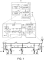
- FIG. 1 illustrates a wireless device 101 having an antenna with an antenna tuner supporting simplified closed-loop antenna tuning (CLAT) algorithm in accordance with one novel aspect.
- Wireless device 101 comprises memory 102 that contains data and program 108, a processor 103, a control and configuration module 104, an application module 105, and a radio frequency (RF) transceiver 106 coupled to antenna 107.
- Memory 102 stores program instructions and data 108 to control the operations of the wireless device via processor 103.
- the RF transceiver converts the baseband signals from the processor to RF signals and sends out to the antenna.
- the processor processes the received baseband signals from the RF transceiver and invokes different functional modules to perform various features and embodiments supported by the wireless device.
- the wireless device 101 is implemented by an antenna assembly 111 and a baseband/radio frequency (BB/RF) module 112.
- Antenna assembly 111 comprises an antenna tuner 121 and a control interface 122.
- BB/RF 112 comprises a digital baseband general purpose IO (DBB GPIO) 131, a transmitter TX 132, a power amplifier PA 133, a Diplexer DPX 134, a single-pole N-throw switch SPnT 135, a coupler 136, and a selector/detector DET 137.
- the antenna tuner 121 is coupled to the RF input (e.g., radio transmitter TX 132 and power amplifier 133).
- the antenna tuner 121 is coupled to antenna 107.
- the coupler 136 couples the signal in the forward path (from single-pole N-throw switch SPnT 135 to tuner 121) and in the reverse path (from tuner 121 to the single-pole N-throw switch SPnT 135).
- the selector/detector DET 137 can sample the forward path and reverse path signal.
- the antenna tuner 121 further comprises a plurality of tunable capacitors C1, C2, C3, and a plurality of inductors L1, L2, L3, and L4 controlled by corresponding switches.
- An antenna tuner matches a radio with a fixed impedance (typically 50 Ohms for modern transceivers) to an antenna.
- CLAT closed-loop antenna tuning
- the goal is to find the optimum settings of the capacitors and the inductors to achieve maximum transducer gain.
- each capacitor can be tuned by a 5-bit number for its capacitance, while each inductor is controlled by an ON/OFF switch.
- the total number of possible settings of the antenna tuner can reach approximately half a million states. Extensive search within the possible tuner states is thus required to achieve a global optimum setting for maximum transducer gain.
- the first order simplification is to transform the search space from tuner states into corresponding S parameter values in the S parameter space.
- tuner states can be transformed into the same S parameter values. Only one tuner state among the redundant tuner states needs to be retained. The selection can be based on common practices in the art of RF design such as avoiding ill-conditioned state that can lead to large errors due to variations in component value. Thus, by transforming from tuner state to S parameter state, a large number of tuner states can be removed. Additionally, the S parameter state can be quantized to further reduce the number of states in S parameter space to, say, a few thousand states.
- a simplified CLAT search algorithm based on maximum RTG (relative transducer gain) and simultaneous conjugate match is proposed.
- RTG relative transducer gain
- simultaneous conjugate match exists
- near optimum solution or possibly optimum solution if simultaneous conjugate match is not possible
- the search region which is independent from antenna load
- Predictable search path with broadband match can be found using extracted lumped element, which typically requires less than 100 iterations.
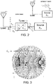
- FIG. 2 illustrates transducer gain and relative transducer gain (RTG) of an antenna with or without an antenna tuner.
- the goal for an antenna is to maximize the delivered power from the source to the load, e.g., to maximize the Transducer Gain.
- 2 1 ⁇
- 2 i n p u t mismatch *
- G T
- 2 i n p u t
- RTG Incident power to antenna w / tuner
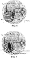
- Figure 3 illustrates a search region on the Smith chart for S22.
- the pre-computed search region indicates simultaneous matches at the source and the load.
- the search region is a circle 301, which represents S22 that satisfies the condition of equation (1): S 22 i n which
- Figure 4 illustrates a search region and the maximum RTG on the Smith chart for S22.
- the search region is a circle 401 that satisfies the same condition as equation (1).
- the value of ⁇ 0.2.
- the maximum RTG can be found somewhere between ⁇ L * (the best load match) and the peak
- pre-computed search region and constant S21 contours derived from approximation allows search to quickly narrow down to near maximum RTG region. Additional fine-search can still be conducted via simple gradient (or hill climbing) search to further refine the RTG. Note that the simplified search leads to a point that is very close to global optimum and further gradient type refinement search can avoid finding the local optimum.
- Figure 5 illustrates one embodiment of how to search for maximum RTG on the Smith chart for S22.
- the search region is a circle 501 that satisfies the same condition as equation (1).
- the search region can be pre-computed based on the condition because it is independent from the load condition.
- the actual search area is limited by the union of the constant contours and the input mismatch boundary as depicted by dashed line 502.
- the final search region is depicted by dashed line 503, and the maximum RTG can be found somewhere between ⁇ L * and the peak
- Figure 6 illustrates how to search for maximum RTG on the Smith chart for S22 when the load reflection coefficient ⁇ L * is outside the search region.
- ⁇ L * is outside the search region 601
- the final search area 602 is modified as depicted in Figure 6 .
- the search result for maximum RTG can be between the closest point in the search region to ⁇ L *. It can result in slight mismatch at the source and the load but the antenna tuner should still have decent RTG.
- Figure 7 illustrates different search regions and composite search region on the Smith chart for S22 under carrier aggregation.
- multiple search regions 701 can be defined, one for each carrier.
- C for carrier 1 as well as the contours of constant
- the composite search region 702 is determined based on the peak
- the antenna tuner 121 has approximately half a million states for the different capacitor and inductor settings, each is represented by a codeword.
- LUT Lookup Table
- S-parameters f(codeword)
- Using lumped element model limits the number of states in the search since it follows the certain trajectory in the Smith chart. It also allows broadband match to be found among multiple solutions.
- S22 can be computed from C, L, switch values.
- the search traverses the path of shunt C or series L "circles" in the Smith chart (change C1, C2, C3, or change the switch for series L). Multiple trajectories are possible.
- the best (broadband) match is achieved when each end-point of the S22 path is close to the center of the Smith chart (50-Ohm point).
- the search strategy should choose the path that is closest to the center of the smith chart to get to ⁇ L *.
- Figure 8 illustrates one embodiment of establishing a Lookup Table (LUT).
- the LUT can be organized for codewords based on constant S21 values or equivalent S22 constant circle (e.g., every 0.25dB of
- are plotted including
- c1,
- c2,
- c3, etc.
- a simple way to reduce the LUT size is to select points on the
- Figure 9 illustrates an example of a Lookup Table (LUT) for codeword based on S21 quantization within the search region.
- the search region is a circle 901 that satisfies the same condition as depicted by equation (1).
- the search region can be pre-computed based on the condition because it is independent from the load condition of antenna.
- Cn (e.g., every -.25dB of
- LUT 903 is organized for codewords as well as corresponding input matching ⁇ . For example, each row corresponds to
- Figure 10 illustrates one example of search strategy for maximum RTG.
- regions can be pre-computed and picking equal contour ⁇ codewords.
- and the conjugate of loading defines an elliptical final search region.
- the pre-computed codewords can be further filtered out (whether in this elliptical final search region).
- RTG search is performed on this set of filtered codewords.
- the search is performed by finding the direction of search angel ⁇ i, which is the direction from the peak
- to ⁇ L *: ⁇ i ⁇ S 21, peak ⁇ ⁇ L *
- 2 1 ⁇
- 2 i n p u t mismatch *
- Figure 11 illustrates search region that is constrained by receiver mismatch.
- the receiver mismatch can occur because of transmit path RTG optimization.
- the load is known a prior but the current source conditions (antenna side) is not known a priori.
- the strategy for maintaining a reasonable receiver match is to restrict the search region in TX S22 to region where receiver source and load match do not deviate significantly from the 50-Ohm point. That is, to prevent excessive receiver mismatch, we can limit the search region within the overlapping area of TX search region, small RX source mismatch region, and small RX load mismatch region.
- the TX search region is depicted by circle 1101 on the Smith chart
- the small RX source mismatch is depicted by circle 1102 which indicates RX S11 ⁇ ⁇ '
- the small RX load mismatch is depicted by circle 1103 which indicates RX S22 ⁇ ⁇ ".
- the restricted region of RX S11 ⁇ ⁇ ' and RX S22 ⁇ ⁇ " within the TX search region 1101 can be pre-computed, resulting an overall search region as depicted by 1104.
- the overall search region provides good TX RTG while maintaining reasonable RX path match.
- the input constraint might not be important because the max RTG corresponds to a Gamma_in not so close to zero.
- FIG 12 is a flow chart of a method of simplified closed-loop antenna tuning (CLAT) algorithm in accordance with one novel aspect.
- a wireless device construct a Smith chart for an antenna with an antenna tuner having S-parameters including S11, S12, S21, and S22.
- the wireless device determines a search region of S22 on the Smith chart that satisfies a condition.
- the search region is pre-computed because the condition is independent from the load condition of the antenna tuner and properly quantized.
- the condition indicates an input reflection coefficient ( ⁇ in) of the antenna tuner is smaller than a threshold value.
- the wireless device estimates a load reflection coefficient ( ⁇ L ) of the antenna tuner.
- the wireless device searches a set of S-parameters that corresponds to a maximum relative transducer gain (RTG) of the antenna on the Smith chart within the search region.
- RMG maximum relative transducer gain
- the search is conducted along a search path that is located inside a final search region formed between a peak
- a simple gradient search can be used to further refine the search.
Landscapes
- Engineering & Computer Science (AREA)
- Computer Networks & Wireless Communication (AREA)
- Signal Processing (AREA)
- Transmitters (AREA)
- Input Circuits Of Receivers And Coupling Of Receivers And Audio Equipment (AREA)
- Details Of Aerials (AREA)
Claims (13)
- Verfahren, aufweisend:(a) Konstruieren eines Smith-Diagramms durch eine Funkvorrichtung für eine Antenne mit einem Antennenabstimmer, der S-Parameter aufweist, wobei der Antennenabstimmer eine Mehrzahl von Kondensatoren und eine Mehrzahl von Spulen aufweist;(b) Bestimmen eines Suchbereichs (401) basierend auf einem S-Parameter auf dem Smith-Diagramm, welcher eine Bedingung erfüllt, wobei der S-Parameter ein Ausgangsanschluss-Spannungsreflektionskoeffizient S22 ist und die Bedingung indiziert, dass ein absoluter Wert eines Eingangsreflektionskoeffizienten ┌in des Antennenabstimmers kleiner ist als ein Schwellenwert;(c) Schätzen eines Lastreflektionskoeffizienten ┌L des Antennenabstimmers; und(d) Suchen eines Satzes von S-Parametern, welcher zu einer maximalen relativen Übertragerverstärkung (RTG) der Antenne innerhalb des Suchbereichs (401) korrespondiert, wobei die Suche entlang von einem vorbestimmten Suchpfad durchgeführt wird, der sich innerhalb eines endgültigen Suchbereichs (402) befindet, welcher zwischen einem Höchstwert einer Durchlassspannungsverstärkung |S21| und einer besten Lastanpassung ┌L· auf dem Smith-Chart ausgebildet ist,Steuern eines Einstellens des Antennenabstimmers, wobei die S-Parameter Funktionen von Code-Wörtern sind, die Einstellungen der Kondensatoren und Spulen repräsentieren.
- Verfahren gemäß Anspruch 1, wobei ein RTG-Wert als ein Verhältnis zwischen einer einfallenden Leistung an die Antenne mit dem Antennenabstimmer und einer einfallenden Leistung an die Antenne ohne den Antennenabstimmer definiert ist, und/oder
wobei insbesondere eine Nachschlagtabelle (LUT) von reduzierter Größe zwischen den S-Parametern und den Code-Wörtern innerhalb des Suchbereichs (401) basierend auf einem vordefinierten Verfahren konstruiert ist, wobei eine Größe der LUT bevorzugt durch Auswählen von Punkten auf oder am nächsten an den Konturen einer konstanten Durchlassspannungsverstärkung |S21| und gleichen Winkeln von Ausgangsanschluss-Spannungsreflektionskoeffizienten S22 auf dem Smith-Diagramm weiter reduziert wird. - Verfahren gemäß Anspruch 1, wobei die beste Lastanpassung ┌L· basierend auf Messungen eines Eingangsreflektionskoeffizienten ┌in des Antennenabstimmers geschätzt wird.
- Verfahren gemäß Anspruch 3, wobei ein Koppler und ein Detektor verwendet werden, um einen Vorwärtspfad und einen Rückwärtspfad von Funksignalen zum Bestimmen des Eingangsreflektionskoeffizienten ┌in des Antennenabstimmers abzutasten.
- Verfahren gemäß Anspruch 1, wobei die Suche an der Grenze des Suchbereichs (401) endet, wenn sich die beste Lastanpassung ┌L· außerhalb des Suchbereichs (401) befindet, und/oder- wobei eine andere einfache gradientenbasierte Suche verwendet wird, um die Suche zu verfeinern, nachdem der vordefinierte Suchpfad vollendet ist, und/oder- wobei der Suchbereich (401) weiter durch eine Empfängerquellenfehlanpassungsbedingung und eine Empfängerlastfehlanpassungsbedingung eingeschränkt ist, und/oder- wobei ein erster Suchbereich für eine erste Trägerfrequenz definiert ist, und wobei ein zweiter Suchbereich für eine zweite Trägerfrequenz definiert ist.
- Funkvorrichtung, aufweisend:einen Prozessor;eine Antenne;einen Antennenabstimmer, der S-Parameter aufweist, wobei die Antennenabstimmerlast mit der Antenne verbunden ist, und wobei die Antennenabstimmerquelle mit einem HF-Sendeempfänger verbunden ist, wobei der Antennenabstimmer eine Mehrzahl von Kondensatoren und eine Mehrzahl von Spulen aufweist;einen Koppler und einen Detektor, welcher einen Vorwärtspfad und einen Rückwärtspfad von HF-Signalen abtastet, um einen Eingangsreflektionskoeffizienten zu bestimmen; undeine Steuerschnittstelle, welche Einstellungen des Antennenabstimmers durch den Prozessor über einen digitalen Basisband-Universal-IO (DBB-GPIO) steuert, wobei ein vorbestimmter Suchbereich eines S-Parameters auf dem Smith-Diagramm, welcher eine Bedingung erfüllt, in dem Prozessor gespeichert ist, wobei der S-Parameter ein Ausgangsanschluss-Spannungsreflektionskoeffizient S22 ist und die Bedingung indiziert, dass ein absoluter Wert eines Eingangsreflektionskoeffizienten ┌in des Antennenabstimmers kleiner ist als ein Schwellenwert, der Prozessor einen Lastreflektionskoeffizienten ┌L des Antennenabstimmers schätzt, einen Satz von S-Parametern sucht, welcher zu einer maximalen relativen Übertragerverstärkung (RTG) der Antenne innerhalb des Suchbereichs (401) korrespondiert, wobei die Suche entlang von einem Suchpfad ausgeführt wird, der sich innerhalb eines endgültigen Suchbereichs (402) befindet, welcher zwischen einem Höchstwert einer Durchlassspannungsverstärkung |S21| und einer besten Lastanpassung ┌L· auf dem Smith-Diagramm ausgebildet ist, und wobei die S-Parameter Funktionen von Code-Wörtern sind, die Einstellungen der Kondensatoren und Spulen repräsentieren.
- Vorrichtung gemäß Anspruch 6, wobei ein RTG-Wert als ein Verhältnis zwischen einer einfallenden Leistung an die Antenne mit dem Antennenabstimmer und einer einfallenden Leistung an die Antenne ohne den Antennenabstimmer definiert ist.
- Vorrichtung gemäß Anspruch 6, wobei eine Nachschlagtabelle (LUT) von reduzierter Größe zwischen den S-Parametern und den Code-Wörtern innerhalb des Suchbereichs konstruiert ist.
- Vorrichtung gemäß Anspruch 8, wobei die LUT-Größe durch Auswählen von Punkten auf oder am nächsten an Konturen einer konstanten Durchlassspannungsverstärkung |S21| und gleichen Winkeln von Ausgangsanschluss-Spannungsreflektionskoeffizienten S22 auf dem Smith-Diagramm weiter reduziert wird.
- Vorrichtung gemäß Anspruch 6, wobei die beste Lastanpassung ┌L· basierend auf Messungen eines Eingangsreflektionskoeffizienten ┌in des Antennenabstimmers geschätzt wird.
- Vorrichtung gemäß Anspruch 6, wobei die Suche an der Grenze des Suchbereichs (401) endet, wenn sich die beste Lastanpassung ┌L· außerhalb des Suchbereichs (401) befindet.
- Vorrichtung gemäß Anspruch 6, wobei der Suchbereich (401) weiter durch eine Empfängerquellenfehlanpassungsbedingung und eine Empfängerlastfehlanpassungsbedingung eingeschränkt ist.
- Vorrichtung gemäß Anspruch 6, wobei ein erster Suchbereich für eine erste Trägerfrequenz definiert ist, und wobei ein zweiter Suchbereich für eine zweite Trägerfrequenz definiert ist.
Applications Claiming Priority (4)
| Application Number | Priority Date | Filing Date | Title |
|---|---|---|---|
| US201462024537P | 2014-07-15 | 2014-07-15 | |
| US201462045088P | 2014-09-03 | 2014-09-03 | |
| US201462080623P | 2014-11-17 | 2014-11-17 | |
| PCT/SG2015/050214 WO2016010483A1 (en) | 2014-07-15 | 2015-07-15 | Method for simplified closed-loop antenna tuning |
Publications (3)
| Publication Number | Publication Date |
|---|---|
| EP3039802A1 EP3039802A1 (de) | 2016-07-06 |
| EP3039802A4 EP3039802A4 (de) | 2016-11-09 |
| EP3039802B1 true EP3039802B1 (de) | 2018-06-06 |
Family
ID=55078837
Family Applications (1)
| Application Number | Title | Priority Date | Filing Date |
|---|---|---|---|
| EP15821557.4A Not-in-force EP3039802B1 (de) | 2014-07-15 | 2015-07-15 | Verfahren zur vereinfachten geschlossenen antennenabstimmung |
Country Status (4)
| Country | Link |
|---|---|
| US (1) | US9401738B2 (de) |
| EP (1) | EP3039802B1 (de) |
| CN (1) | CN106165317B (de) |
| WO (1) | WO2016010483A1 (de) |
Families Citing this family (7)
| Publication number | Priority date | Publication date | Assignee | Title |
|---|---|---|---|---|
| DE102013109463A1 (de) * | 2013-08-30 | 2015-03-05 | Endress + Hauser Gmbh + Co. Kg | Verfahren zur Optimierung der Impedanz eines Verbindungselements |
| US9762267B2 (en) * | 2015-01-21 | 2017-09-12 | Mediatek Inc. | Detection path design for communication systems |
| KR102468231B1 (ko) | 2016-07-22 | 2022-11-18 | 삼성전자주식회사 | 무선 통신 시스템에서 안테나 임피던스 매칭 장치 및 방법 |
| DE102018106029A1 (de) * | 2018-03-15 | 2019-09-19 | RF360 Europe GmbH | Verstärkungsregelungs-Filterschaltung, eine Filterschaltung umfassendes Leistungsmodul und ein Verfahren zum Justieren einer HF-Filterschaltung, um eine steuerbare Verstärkung bereitzustellen |
| CN110365425B (zh) * | 2018-04-09 | 2021-10-26 | 北京紫光展锐通信技术有限公司 | 天线调谐控制方法、装置及系统 |
| US11438850B2 (en) | 2020-09-09 | 2022-09-06 | Samsung Electronics Co., Ltd. | Data-driven methods for look up table-free closed-loop antenna impedance tuning |
| US12074648B2 (en) * | 2022-09-21 | 2024-08-27 | Qualcomm Incorporated | In-device characterization of antenna coupling |
Family Cites Families (14)
| Publication number | Priority date | Publication date | Assignee | Title |
|---|---|---|---|---|
| GB2377082A (en) * | 2001-06-29 | 2002-12-31 | Nokia Corp | Two element antenna system |
| US7990319B2 (en) * | 2005-04-27 | 2011-08-02 | Epcos Ag | Radio device having antenna arrangement suited for operating over a plurality of bands |
| JP4825582B2 (ja) * | 2006-05-24 | 2011-11-30 | 富士通株式会社 | 無線タグ及び無線タグ用アンテナ |
| US8638266B2 (en) * | 2008-07-24 | 2014-01-28 | Nxp, B.V. | Antenna arrangement and a radio apparatus including the antenna arrangement |
| US8774743B2 (en) | 2009-10-14 | 2014-07-08 | Blackberry Limited | Dynamic real-time calibration for antenna matching in a radio frequency receiver system |
| KR101088831B1 (ko) | 2010-01-26 | 2011-12-06 | 광주과학기술원 | 부하 임피던스 변화에 둔감한 전력 증폭기 |
| CN101740855B (zh) * | 2010-01-28 | 2014-01-08 | 福建三元达软件有限公司 | 天线的协同设计及安装方法 |
| US8233851B2 (en) | 2010-02-03 | 2012-07-31 | Avago Technologies Wireless Ip (Singapore) Pte. Ltd. | Method and apparatus for providing impedance matching for high-frequency signal transmitter |
| KR101176286B1 (ko) * | 2010-08-02 | 2012-08-22 | 엘지이노텍 주식회사 | Swr 정보를 이용한 임피던스 매칭장치 및 방법 |
| WO2012024517A1 (en) * | 2010-08-18 | 2012-02-23 | Wispry, Inc. | Tuning methods for tunable matching networks |
| WO2012042748A1 (ja) * | 2010-09-30 | 2012-04-05 | パナソニック株式会社 | 無線通信機 |
| US9178488B2 (en) | 2011-03-21 | 2015-11-03 | Wispry, Inc. | Simple and minimally invasive methods and systems for sensing and computing load impedance |
| JP5856305B2 (ja) * | 2012-09-04 | 2016-02-09 | パイオニア株式会社 | 整合装置、インピーダンス整合方法及びコンピュータプログラム |
| US9203500B2 (en) * | 2013-05-22 | 2015-12-01 | Blackberry Limited | Method and apparatus for calibrating an iterative matching network tuner |
-
2015
- 2015-07-14 US US14/799,413 patent/US9401738B2/en active Active
- 2015-07-15 EP EP15821557.4A patent/EP3039802B1/de not_active Not-in-force
- 2015-07-15 CN CN201580009183.6A patent/CN106165317B/zh not_active Expired - Fee Related
- 2015-07-15 WO PCT/SG2015/050214 patent/WO2016010483A1/en not_active Ceased
Non-Patent Citations (1)
| Title |
|---|
| None * |
Also Published As
| Publication number | Publication date |
|---|---|
| WO2016010483A1 (en) | 2016-01-21 |
| EP3039802A1 (de) | 2016-07-06 |
| CN106165317B (zh) | 2018-09-18 |
| US9401738B2 (en) | 2016-07-26 |
| CN106165317A (zh) | 2016-11-23 |
| EP3039802A4 (de) | 2016-11-09 |
| US20160020814A1 (en) | 2016-01-21 |
Similar Documents
| Publication | Publication Date | Title |
|---|---|---|
| EP3039802B1 (de) | Verfahren zur vereinfachten geschlossenen antennenabstimmung | |
| US11502410B2 (en) | System apparatus and method for matching antenna impedance in a wireless communication system | |
| US9002278B2 (en) | Simple automatic antenna tuning system and method | |
| EP2751928B1 (de) | Antenneneinstellung auf einem impedanzverlaufsweg | |
| EP2557688B1 (de) | Steuerung für eine Funkschaltung | |
| US20180323770A1 (en) | Variable filter | |
| US9048536B2 (en) | Mobile communication device and impedance matching method thereof | |
| US10084489B2 (en) | Multiple antenna system and transceiver front end for interband downlink carrier aggregation | |
| JP5435309B2 (ja) | 方向性結合器および無線通信装置 | |
| EP2661031A1 (de) | Verfahren und mobiles endgerät zur verbesserung einer antennenanpassungsleistung eines mobilen mehrband-endgerätes | |
| US20240322782A1 (en) | Machine-learning based tuning algorithm for duplexer systems | |
| CN103546188A (zh) | 一种自调谐天线的无线移动终端及其调节方法 | |
| US20160285482A1 (en) | High-frequency circuit and transmission and reception circuit using high-frequency circuit | |
| WO2017201978A1 (zh) | 射频发射电路、电路匹配方法及计算机存储介质 | |
| CN114698404B (zh) | 一种天线调谐装置及方法 | |
| TW201926923A (zh) | 無線通訊裝置 | |
| CN107979388A (zh) | 一种超短波宽带收发信机的滤波器组装置 | |
| US9014245B2 (en) | Method and apparatus for compensating for phase shift in a communication device | |
| US7587182B2 (en) | Receiver input circuit | |
| GB2531520A (en) | Antenna impedance matching with negative impedance converters | |
| CN117388813A (zh) | 一种提高全双工收发芯片收发隔离度校准方法及系统 | |
| US20080030421A1 (en) | Antenna Architecture and Lc Coupler | |
| US20190123887A1 (en) | Simultaneous bidirectional full duplex link |
Legal Events
| Date | Code | Title | Description |
|---|---|---|---|
| PUAI | Public reference made under article 153(3) epc to a published international application that has entered the european phase |
Free format text: ORIGINAL CODE: 0009012 |
|
| 17P | Request for examination filed |
Effective date: 20160329 |
|
| AK | Designated contracting states |
Kind code of ref document: A1 Designated state(s): AL AT BE BG CH CY CZ DE DK EE ES FI FR GB GR HR HU IE IS IT LI LT LU LV MC MK MT NL NO PL PT RO RS SE SI SK SM TR |
|
| AX | Request for extension of the european patent |
Extension state: BA ME |
|
| A4 | Supplementary search report drawn up and despatched |
Effective date: 20161010 |
|
| RIC1 | Information provided on ipc code assigned before grant |
Ipc: H03H 7/40 20060101AFI20161004BHEP Ipc: H03H 7/38 20060101ALI20161004BHEP Ipc: H04B 1/04 20060101ALI20161004BHEP Ipc: H01Q 5/335 20150101ALN20161004BHEP Ipc: H04B 1/18 20060101ALN20161004BHEP |
|
| DAV | Request for validation of the european patent (deleted) | ||
| DAX | Request for extension of the european patent (deleted) | ||
| RIC1 | Information provided on ipc code assigned before grant |
Ipc: H04B 1/04 20060101ALI20171117BHEP Ipc: H03H 7/40 20060101AFI20171117BHEP Ipc: H01Q 5/335 20150101ALN20171117BHEP Ipc: H04B 1/18 20060101ALN20171117BHEP Ipc: H03H 7/38 20060101ALI20171117BHEP |
|
| GRAP | Despatch of communication of intention to grant a patent |
Free format text: ORIGINAL CODE: EPIDOSNIGR1 |
|
| INTG | Intention to grant announced |
Effective date: 20180102 |
|
| GRAJ | Information related to disapproval of communication of intention to grant by the applicant or resumption of examination proceedings by the epo deleted |
Free format text: ORIGINAL CODE: EPIDOSDIGR1 |
|
| REG | Reference to a national code |
Ref country code: DE Ref legal event code: R079 Ref document number: 602015012089 Country of ref document: DE Free format text: PREVIOUS MAIN CLASS: H04B0017120000 Ipc: H03H0007400000 |
|
| GRAR | Information related to intention to grant a patent recorded |
Free format text: ORIGINAL CODE: EPIDOSNIGR71 |
|
| GRAS | Grant fee paid |
Free format text: ORIGINAL CODE: EPIDOSNIGR3 |
|
| INTC | Intention to grant announced (deleted) | ||
| GRAA | (expected) grant |
Free format text: ORIGINAL CODE: 0009210 |
|
| RIC1 | Information provided on ipc code assigned before grant |
Ipc: H03H 7/38 20060101ALI20180409BHEP Ipc: H03H 7/40 20060101AFI20180409BHEP Ipc: H04B 1/04 20060101ALI20180409BHEP Ipc: H01Q 5/335 20150101ALN20180409BHEP Ipc: H04B 1/18 20060101ALN20180409BHEP |
|
| INTG | Intention to grant announced |
Effective date: 20180420 |
|
| AK | Designated contracting states |
Kind code of ref document: B1 Designated state(s): AL AT BE BG CH CY CZ DE DK EE ES FI FR GB GR HR HU IE IS IT LI LT LU LV MC MK MT NL NO PL PT RO RS SE SI SK SM TR |
|
| REG | Reference to a national code |
Ref country code: GB Ref legal event code: FG4D |
|
| REG | Reference to a national code |
Ref country code: CH Ref legal event code: EP Ref country code: AT Ref legal event code: REF Ref document number: 1007152 Country of ref document: AT Kind code of ref document: T Effective date: 20180615 |
|
| REG | Reference to a national code |
Ref country code: IE Ref legal event code: FG4D |
|
| REG | Reference to a national code |
Ref country code: DE Ref legal event code: R096 Ref document number: 602015012089 Country of ref document: DE |
|
| REG | Reference to a national code |
Ref country code: FR Ref legal event code: PLFP Year of fee payment: 4 |
|
| REG | Reference to a national code |
Ref country code: NL Ref legal event code: MP Effective date: 20180606 |
|
| REG | Reference to a national code |
Ref country code: LT Ref legal event code: MG4D |
|
| PG25 | Lapsed in a contracting state [announced via postgrant information from national office to epo] |
Ref country code: BG Free format text: LAPSE BECAUSE OF FAILURE TO SUBMIT A TRANSLATION OF THE DESCRIPTION OR TO PAY THE FEE WITHIN THE PRESCRIBED TIME-LIMIT Effective date: 20180906 Ref country code: NO Free format text: LAPSE BECAUSE OF FAILURE TO SUBMIT A TRANSLATION OF THE DESCRIPTION OR TO PAY THE FEE WITHIN THE PRESCRIBED TIME-LIMIT Effective date: 20180906 Ref country code: FI Free format text: LAPSE BECAUSE OF FAILURE TO SUBMIT A TRANSLATION OF THE DESCRIPTION OR TO PAY THE FEE WITHIN THE PRESCRIBED TIME-LIMIT Effective date: 20180606 Ref country code: SE Free format text: LAPSE BECAUSE OF FAILURE TO SUBMIT A TRANSLATION OF THE DESCRIPTION OR TO PAY THE FEE WITHIN THE PRESCRIBED TIME-LIMIT Effective date: 20180606 Ref country code: CY Free format text: LAPSE BECAUSE OF FAILURE TO SUBMIT A TRANSLATION OF THE DESCRIPTION OR TO PAY THE FEE WITHIN THE PRESCRIBED TIME-LIMIT Effective date: 20180606 Ref country code: ES Free format text: LAPSE BECAUSE OF FAILURE TO SUBMIT A TRANSLATION OF THE DESCRIPTION OR TO PAY THE FEE WITHIN THE PRESCRIBED TIME-LIMIT Effective date: 20180606 Ref country code: LT Free format text: LAPSE BECAUSE OF FAILURE TO SUBMIT A TRANSLATION OF THE DESCRIPTION OR TO PAY THE FEE WITHIN THE PRESCRIBED TIME-LIMIT Effective date: 20180606 |
|
| PGFP | Annual fee paid to national office [announced via postgrant information from national office to epo] |
Ref country code: FR Payment date: 20180727 Year of fee payment: 4 Ref country code: DE Payment date: 20180611 Year of fee payment: 4 |
|
| PG25 | Lapsed in a contracting state [announced via postgrant information from national office to epo] |
Ref country code: HR Free format text: LAPSE BECAUSE OF FAILURE TO SUBMIT A TRANSLATION OF THE DESCRIPTION OR TO PAY THE FEE WITHIN THE PRESCRIBED TIME-LIMIT Effective date: 20180606 Ref country code: RS Free format text: LAPSE BECAUSE OF FAILURE TO SUBMIT A TRANSLATION OF THE DESCRIPTION OR TO PAY THE FEE WITHIN THE PRESCRIBED TIME-LIMIT Effective date: 20180606 Ref country code: GR Free format text: LAPSE BECAUSE OF FAILURE TO SUBMIT A TRANSLATION OF THE DESCRIPTION OR TO PAY THE FEE WITHIN THE PRESCRIBED TIME-LIMIT Effective date: 20180907 Ref country code: LV Free format text: LAPSE BECAUSE OF FAILURE TO SUBMIT A TRANSLATION OF THE DESCRIPTION OR TO PAY THE FEE WITHIN THE PRESCRIBED TIME-LIMIT Effective date: 20180606 |
|
| REG | Reference to a national code |
Ref country code: AT Ref legal event code: MK05 Ref document number: 1007152 Country of ref document: AT Kind code of ref document: T Effective date: 20180606 |
|
| PG25 | Lapsed in a contracting state [announced via postgrant information from national office to epo] |
Ref country code: NL Free format text: LAPSE BECAUSE OF FAILURE TO SUBMIT A TRANSLATION OF THE DESCRIPTION OR TO PAY THE FEE WITHIN THE PRESCRIBED TIME-LIMIT Effective date: 20180606 |
|
| PG25 | Lapsed in a contracting state [announced via postgrant information from national office to epo] |
Ref country code: CZ Free format text: LAPSE BECAUSE OF FAILURE TO SUBMIT A TRANSLATION OF THE DESCRIPTION OR TO PAY THE FEE WITHIN THE PRESCRIBED TIME-LIMIT Effective date: 20180606 Ref country code: IS Free format text: LAPSE BECAUSE OF FAILURE TO SUBMIT A TRANSLATION OF THE DESCRIPTION OR TO PAY THE FEE WITHIN THE PRESCRIBED TIME-LIMIT Effective date: 20181006 Ref country code: RO Free format text: LAPSE BECAUSE OF FAILURE TO SUBMIT A TRANSLATION OF THE DESCRIPTION OR TO PAY THE FEE WITHIN THE PRESCRIBED TIME-LIMIT Effective date: 20180606 Ref country code: EE Free format text: LAPSE BECAUSE OF FAILURE TO SUBMIT A TRANSLATION OF THE DESCRIPTION OR TO PAY THE FEE WITHIN THE PRESCRIBED TIME-LIMIT Effective date: 20180606 Ref country code: AT Free format text: LAPSE BECAUSE OF FAILURE TO SUBMIT A TRANSLATION OF THE DESCRIPTION OR TO PAY THE FEE WITHIN THE PRESCRIBED TIME-LIMIT Effective date: 20180606 Ref country code: PL Free format text: LAPSE BECAUSE OF FAILURE TO SUBMIT A TRANSLATION OF THE DESCRIPTION OR TO PAY THE FEE WITHIN THE PRESCRIBED TIME-LIMIT Effective date: 20180606 Ref country code: SK Free format text: LAPSE BECAUSE OF FAILURE TO SUBMIT A TRANSLATION OF THE DESCRIPTION OR TO PAY THE FEE WITHIN THE PRESCRIBED TIME-LIMIT Effective date: 20180606 |
|
| PG25 | Lapsed in a contracting state [announced via postgrant information from national office to epo] |
Ref country code: SM Free format text: LAPSE BECAUSE OF FAILURE TO SUBMIT A TRANSLATION OF THE DESCRIPTION OR TO PAY THE FEE WITHIN THE PRESCRIBED TIME-LIMIT Effective date: 20180606 Ref country code: IT Free format text: LAPSE BECAUSE OF FAILURE TO SUBMIT A TRANSLATION OF THE DESCRIPTION OR TO PAY THE FEE WITHIN THE PRESCRIBED TIME-LIMIT Effective date: 20180606 |
|
| REG | Reference to a national code |
Ref country code: CH Ref legal event code: PL |
|
| REG | Reference to a national code |
Ref country code: DE Ref legal event code: R097 Ref document number: 602015012089 Country of ref document: DE |
|
| PG25 | Lapsed in a contracting state [announced via postgrant information from national office to epo] |
Ref country code: MC Free format text: LAPSE BECAUSE OF FAILURE TO SUBMIT A TRANSLATION OF THE DESCRIPTION OR TO PAY THE FEE WITHIN THE PRESCRIBED TIME-LIMIT Effective date: 20180606 Ref country code: LU Free format text: LAPSE BECAUSE OF NON-PAYMENT OF DUE FEES Effective date: 20180715 |
|
| REG | Reference to a national code |
Ref country code: BE Ref legal event code: MM Effective date: 20180731 |
|
| PLBE | No opposition filed within time limit |
Free format text: ORIGINAL CODE: 0009261 |
|
| STAA | Information on the status of an ep patent application or granted ep patent |
Free format text: STATUS: NO OPPOSITION FILED WITHIN TIME LIMIT |
|
| REG | Reference to a national code |
Ref country code: IE Ref legal event code: MM4A |
|
| PG25 | Lapsed in a contracting state [announced via postgrant information from national office to epo] |
Ref country code: IE Free format text: LAPSE BECAUSE OF NON-PAYMENT OF DUE FEES Effective date: 20180715 Ref country code: CH Free format text: LAPSE BECAUSE OF NON-PAYMENT OF DUE FEES Effective date: 20180731 Ref country code: LI Free format text: LAPSE BECAUSE OF NON-PAYMENT OF DUE FEES Effective date: 20180731 |
|
| 26N | No opposition filed |
Effective date: 20190307 |
|
| PG25 | Lapsed in a contracting state [announced via postgrant information from national office to epo] |
Ref country code: DK Free format text: LAPSE BECAUSE OF FAILURE TO SUBMIT A TRANSLATION OF THE DESCRIPTION OR TO PAY THE FEE WITHIN THE PRESCRIBED TIME-LIMIT Effective date: 20180606 Ref country code: BE Free format text: LAPSE BECAUSE OF NON-PAYMENT OF DUE FEES Effective date: 20180731 Ref country code: SI Free format text: LAPSE BECAUSE OF FAILURE TO SUBMIT A TRANSLATION OF THE DESCRIPTION OR TO PAY THE FEE WITHIN THE PRESCRIBED TIME-LIMIT Effective date: 20180606 |
|
| PG25 | Lapsed in a contracting state [announced via postgrant information from national office to epo] |
Ref country code: AL Free format text: LAPSE BECAUSE OF FAILURE TO SUBMIT A TRANSLATION OF THE DESCRIPTION OR TO PAY THE FEE WITHIN THE PRESCRIBED TIME-LIMIT Effective date: 20180606 |
|
| PG25 | Lapsed in a contracting state [announced via postgrant information from national office to epo] |
Ref country code: MT Free format text: LAPSE BECAUSE OF NON-PAYMENT OF DUE FEES Effective date: 20180715 |
|
| REG | Reference to a national code |
Ref country code: DE Ref legal event code: R119 Ref document number: 602015012089 Country of ref document: DE |
|
| GBPC | Gb: european patent ceased through non-payment of renewal fee |
Effective date: 20190715 |
|
| PG25 | Lapsed in a contracting state [announced via postgrant information from national office to epo] |
Ref country code: TR Free format text: LAPSE BECAUSE OF FAILURE TO SUBMIT A TRANSLATION OF THE DESCRIPTION OR TO PAY THE FEE WITHIN THE PRESCRIBED TIME-LIMIT Effective date: 20180606 |
|
| PG25 | Lapsed in a contracting state [announced via postgrant information from national office to epo] |
Ref country code: DE Free format text: LAPSE BECAUSE OF NON-PAYMENT OF DUE FEES Effective date: 20200201 Ref country code: GB Free format text: LAPSE BECAUSE OF NON-PAYMENT OF DUE FEES Effective date: 20190715 |
|
| PG25 | Lapsed in a contracting state [announced via postgrant information from national office to epo] |
Ref country code: PT Free format text: LAPSE BECAUSE OF FAILURE TO SUBMIT A TRANSLATION OF THE DESCRIPTION OR TO PAY THE FEE WITHIN THE PRESCRIBED TIME-LIMIT Effective date: 20180606 |
|
| PG25 | Lapsed in a contracting state [announced via postgrant information from national office to epo] |
Ref country code: FR Free format text: LAPSE BECAUSE OF NON-PAYMENT OF DUE FEES Effective date: 20190731 Ref country code: HU Free format text: LAPSE BECAUSE OF FAILURE TO SUBMIT A TRANSLATION OF THE DESCRIPTION OR TO PAY THE FEE WITHIN THE PRESCRIBED TIME-LIMIT; INVALID AB INITIO Effective date: 20150715 Ref country code: MK Free format text: LAPSE BECAUSE OF NON-PAYMENT OF DUE FEES Effective date: 20180606 |