EP3040023B1 - Filtervorrichtung und Verfahren zum Herstellen einer Filtervorrichtung - Google Patents
Filtervorrichtung und Verfahren zum Herstellen einer Filtervorrichtung Download PDFInfo
- Publication number
- EP3040023B1 EP3040023B1 EP14200629.5A EP14200629A EP3040023B1 EP 3040023 B1 EP3040023 B1 EP 3040023B1 EP 14200629 A EP14200629 A EP 14200629A EP 3040023 B1 EP3040023 B1 EP 3040023B1
- Authority
- EP
- European Patent Office
- Prior art keywords
- filter
- opening
- primary
- channel
- protruding member
- Prior art date
- Legal status (The legal status is an assumption and is not a legal conclusion. Google has not performed a legal analysis and makes no representation as to the accuracy of the status listed.)
- Not-in-force
Links
Images





Classifications
-
- A—HUMAN NECESSITIES
- A61—MEDICAL OR VETERINARY SCIENCE; HYGIENE
- A61B—DIAGNOSIS; SURGERY; IDENTIFICATION
- A61B5/00—Measuring for diagnostic purposes; Identification of persons
- A61B5/12—Audiometering
-
- A—HUMAN NECESSITIES
- A61—MEDICAL OR VETERINARY SCIENCE; HYGIENE
- A61B—DIAGNOSIS; SURGERY; IDENTIFICATION
- A61B5/00—Measuring for diagnostic purposes; Identification of persons
- A61B5/68—Arrangements of detecting, measuring or recording means, e.g. sensors, in relation to patient
- A61B5/6801—Arrangements of detecting, measuring or recording means, e.g. sensors, in relation to patient specially adapted to be attached to or worn on the body surface
- A61B5/6813—Specially adapted to be attached to a specific body part
- A61B5/6814—Head
- A61B5/6815—Ear
- A61B5/6817—Ear canal
-
- H—ELECTRICITY
- H04—ELECTRIC COMMUNICATION TECHNIQUE
- H04R—LOUDSPEAKERS, MICROPHONES, GRAMOPHONE PICK-UPS OR LIKE ACOUSTIC ELECTROMECHANICAL TRANSDUCERS; ELECTRIC HEARING AIDS; PUBLIC ADDRESS SYSTEMS
- H04R25/00—Electric hearing aids
- H04R25/65—Housing parts, e.g. shells, tips or moulds, or their manufacture
- H04R25/652—Ear tips; Ear moulds
- H04R25/654—Ear wax retarders
-
- H—ELECTRICITY
- H04—ELECTRIC COMMUNICATION TECHNIQUE
- H04R—LOUDSPEAKERS, MICROPHONES, GRAMOPHONE PICK-UPS OR LIKE ACOUSTIC ELECTROMECHANICAL TRANSDUCERS; ELECTRIC HEARING AIDS; PUBLIC ADDRESS SYSTEMS
- H04R25/00—Electric hearing aids
- H04R25/65—Housing parts, e.g. shells, tips or moulds, or their manufacture
- H04R25/658—Manufacture of housing parts
-
- A—HUMAN NECESSITIES
- A61—MEDICAL OR VETERINARY SCIENCE; HYGIENE
- A61B—DIAGNOSIS; SURGERY; IDENTIFICATION
- A61B2562/00—Details of sensors; Constructional details of sensor housings or probes; Accessories for sensors
- A61B2562/18—Shielding or protection of sensors from environmental influences, e.g. protection from mechanical damage
Definitions
- the present disclosure relates to a filter device, e.g. for audiologic test equipment, for preventing cerumen, commonly known as earwax, from entering into a compartment comprising delicate equipment, such as a microphone and/or a speaker.
- the compartment may be a compartment of a hearing test probe used to perform audiologic tests, such as tympanometric and/or otoacoustic emission tests.
- a probe In order to perform an audiologic test a probe needs to be inserted into the ear canal of a person to be tested.
- the probe may hold audio devices, such as a microphone and/or one or more speakers. These components may be damaged or altered by cerumen from the person's ear. Therefore a filter device may be applied to the probe between the components of the probe and the distal end of the probe which is to be inserted into the ear canal.
- the filter device needs to enable sound and air to pass through in order for the audiologic tests to be performed. Concurrently the filter needs to stop cerumen from passing into the probe and thereby potentially damaging components of the probe. Conventional filter devices trap cerumen from the user's ear in order to prevent the cerumen from entering into the probe compartment. However, when cerumen is trapped in the filter, the acoustic properties of the probe may be altered, thereby leading to reduced functionality of the probe.
- openings of very small dimensions are desirable.
- a filter device with openings of very small dimensions is disclosed in US 2012/0014548 A1 .
- a filter device is provided, as defined in claim 1.
- the filter device extends along a center axis in a first direction from a first end to a second end.
- the filter device comprises: a first part having a first filter structure; a second part having a second filter structure; and a first channel extending along the center axis.
- the first part and the second part are joined together, and the first filter structure and the second filter structure define a filter element with a first set of filter openings for the first channel.
- a method for providing and/or manufacturing a filter device such as a filter device with a first channel.
- the method comprises: obtaining a first part with a first filter structure; obtaining a second part with a second filter structure; and joining the first part and the second part.
- Joining the first part and the second part comprises at least partly inserting the first filter structure into the second filter structure to form a filter element with a first set of filter openings for the first channel.
- a hearing test probe comprising a filter device as disclosed herein is provided.
- a filter device which may be manufactured cheaply by simple processes such as plastic molding is provided.
- a filter device which lowers manufacturing costs may provide a filter device which may be exchanged after each use and/or after a few uses, and thereby provides for easy usage and highly reliable and consistent measurements.
- the filter device comprises a first channel extending along the center axis.
- the filter element has a first set of filter openings for the first channel.
- the filter device may comprise a second channel extending along the center axis.
- the filter element may have a second set of filter openings for the second channel.
- the first set of filter openings may provide fluid communication between the first channel and the surroundings.
- the second set of filter openings may provide fluid communication between the second channel and the surroundings.
- the filter device may comprise a plurality of channels including the first channel, the second channel and/or a third channel extending along the center axis.
- the channel(s) may at least partly be formed by the first part and/or the second part.
- the filter device may have dimensions such that the filter device or part of the filter device may be inserted into a human ear.
- the filter device may have a length along the center axis, e.g a length less than 15 cm, such as between 0.5 cm and 10 cm, such as between 1 cm and 5 cm, such between 1.5 cm and 3 cm.
- the filter element may have a plurality of sets of filter openings for the plurality of channels.
- the plurality of sets of filter openings for the plurality of channels may include the first set of filter openings for the first channel and the second set of filter openings for the second channel.
- the filter element may include a third set of filter openings for a third channel.
- the filter element may include a fourth set of filter openings for a fourh channel.
- a set of filter openings may comprise one, two, three, four, five six, seven or more filter openings, e.g. in the range from one to ten filter openings.
- a filter opening such as a filter opening of a set of filter openings, may have a cross-sectional shape in a plane perpendicular to the center axis.
- the cross-sectional shape may be a slit, such as a slit resembling the perimeter or part of a perimeter of a geometrical shape, such as a circle, a rectangle, or an oval.
- the slit may have a width less than 0.5 mm, such as less than 0.35 mm. such as less than 0.2 mm, such as less than 0.15 mm, such as less than 0.1 mm.
- the slit may have a constant width and/or a varying width.
- the filter device e.g. the first part, may comprise a tube part with a cavity.
- the tube part may form outer wall part of one or more channels.
- the tube part may at least partly enclose the channel(s).
- the tube part may extend along the center axis.
- the tube part may have a length less than 10 cm, such as between 0.1 cm and 7 cm, such as between 0.5 cm and 5 cm, such between 1 cm and 3 cm.
- the tube part may have a circular cross section and/or the tube part may have an oval cross section, and/or the tube part may have a polygonal cross section, and/or the tube part may have a rectangular cross section.
- the tube part may have a cross-sectional dimension, e.g.
- a cross-sectional dimension in a plane with a normal parallel to the center axis such as a diameter and/or a width.
- the cross-sectional dimension may be selected such that the tube part may be inserted into a human ear canal.
- the cross-sectional dimension may be less than 2 cm, such as between 0.1 cm and 1.5 cm, such as between 0.2 cm and 1 cm, such as between 0.3 cm and 0.8 cm, such as 0.5 cm.
- the filter device e.g. the second part, may comprise a channel separator extending inside the cavity along the center axis to form the plurality of channels, such as the first channel and the second channel.
- the channel separator may have a length substantially similar to the length of the tube part.
- the channel separator may have a length shorter than the length of the tube part, such as 0.1 cm shorter than the length of the tube part.
- the channel separator may have a length less than 10 cm, such as between 0.1 cm and 7 cm, such as between 0.5 cm and 5 cm, such between 1 cm and 3 cm.
- the channel separator may form one or more inner walls, including a first inner wall and/or a second inner wall.
- the one or more inner walls may radially extend from an intersection, e.g. an intersection extending along the center axis.
- the channel separator may form four inner walls radially extending from an intersection of the four inner walls extending along the center axis.
- One or more inner walls of the channel seperator may have a width in a direction perpendicular to the center axis.
- the width may be selected such that the one or more inner walls radially extend to an inner side of the cavity of the tube part.
- the width of one or more inner walls may be less than 10 mm, such as between 1 mm and 8 mm, such as between 2 mm and 6 mm, such as 3 mm.
- the first filter structure may comprise a protruding member and/or a plurality of protruding members, such as a first primary protruding member, a first secondary protruding member, a second primary protruding member, and/or a second secondary protruding member.
- the protruding member(s) may extend along the center axis.
- the protruding member and/or the plurality of protruding members may have a distal end.
- the protruding member and/or the plurality of protruding members may have a length parallel to the center axis between 0.1 and 10 mm, such as between 0.5 mm and 8 mm, such as 1 mm 3 mm or 5 mm.
- the second filter structure may comprise an opening and/or a plurality of openings, such as first opening(s) and second opening(s), the first opening(s) e.g. including a first primary opening and/or a first secondary opening, and the second opening(s) e.g. including a second primary opening and/or a second secondary opening.
- the second filter structure may comprise third opening(s) and fourth opening(s), the third opening(s) e.g. including a third primary opening and/or a third secondary opening, and the fourth opening(s) e.g. including a fourth primary opening and/or a fourth secondary opening.
- a protruding member may extend at least partly inside (e.g. overlap of at least 0.5 mm along the center axis) or through an opening of the second filter structure along the center axis to form a filter opening of a set of filter openings.
- the first primary protruding member may extend at least partly inside or through the first primary opening along the center axis, e.g. with an overlap of at least 0.5 mm, to form a primary first filter opening of the first set of filter openings.
- the first secondary protruding member may extend at least partly inside or through the first secondary opening along the center axis, e.g. with an overlap of at least 0.5 mm) to form a secondary first filter opening of the first set of filter openings.
- the second primary protruding member may extend inside or through the second primary opening along the center axis to form a primary second filter opening of the second set of filter openings.
- the second secondary protruding member may extend inside or through the second secondary opening along the center axis to form a secondary second filter opening of the second set of filter openings.
- Third protruding member(s) may extend at least partly inside or through third opening(s) of the second filter element along the center axis to form third filter opening(s) of the third set of filter openings.
- Fourth protruding member(s) may extend at least partly inside or through fourth opening(s) of the second filter element along the center axis to form fourth filter opening(s) of the fourth set of filter openings.
- a plurality of protruding members may extend into or share the same filter opening.
- a protruding member and/or a plurality of protruding members such as the first primary protruding member, the first secondary protruding member, the second primary protruding member, and/or the second secondary protruding member, may have a circular, oval, oblong, triangular, and/or rectangular cross-section.
- One or more protruding members with an oblong cross-section may be preferred due to size requirements and acoustic properties.
- the cross sectional area of a protruding member and/or the plurality of protruding members may decrease towards the distal end of the protruding member.
- the cross-sectional area of the first primary protruding member may decrease towards the distal end of the first primary protruding member. This may facilitate moulding of the filter structure and/or simplify moulding tools.
- the cross-section of the protruding member and/or the plurality of protruding members may be in a plane having a normal parallel to the center axis.
- the opening and/or the plurality of openings may have a circular, oval, oblong, triangular, and/or rectangular cross-section.
- One or more openings with an oblong or oval cross-section may be preferred due to size requirements and acoustic properties.
- the cross-section of the opening and/or the plurality of openings may be in a plane having a normal parallel to the center axis.
- An opening such as an opening of the plurality of openings, such as the first primary opening, the first secondary opening, the second primary opening, and/or the second secondary opening, may have a cross-sectional area.
- the cross-sectional area of an opening may be selected to allow one or more protruding members to extend inside the opening.
- the cross-sectional area of an opening may be less than 30 mm 2 , such as between 1 mm 2 and 20 mm 2 , such as between 2 mm 2 and 15 mm 2 .
- the protruding member and/or the plurality of protruding members may comprise one or more support points, such as a first support point and/or a second support point.
- the one or more support points may when assembled contact an inner sidewall of the opening in the second filter structure.
- the first support point of the first primary protruding member may contact a first inner sidewall of the first primary opening in the second filter structure when the filter device is assembled.
- Providing support points may provide enhanced precision of the filter opening size, reducing variation in acoustic properties. Furthermore, support points may allow for subsequent fusing of the first part and the second part, e.g. by ultrasonic welding.
- the second part may comprise a coupling part and/or a plurality of coupling parts, such as a first coupling part and/or a second coupling part, for coupling a channel, such as the first channel and/or the second channel, to a probe channel.
- the coupling part and/or the plurality of coupling parts may comprise a coupling ridge extending in the first direction and enclosing the opening and/or the plurality of openings, such as the first primary opening, the first secondary opening, the second primary opening, and/or the second secondary opening.
- the first coupling part may comprise a coupling ridge extending in the first direction and enclosing the first primary opening and/or the first secondary opening.
- the second coupling part may comprise a coupling ridge extending in the first direction and enclosing the second primary opening and/or the second secondary opening.
- the first part and/or the second part may be at least partly coated with a hydrophobic substance.
- the first filter structure and/or the second filter structure may be at least partly coated with a hydrophobic substance.
- inside surfaces of the filter openings may be coated with a hydrophobic substance, e.g. the protruding member and/or the plurality of protruding members and/or the opening and/or the plurality of openings may be at least partly coated with a hydrophobic substance.
- Coating a surface with a hydrophobic substance will provide cerumen to be attracted to the surface, thus at least partly trapping the cerumen inside the filter openings, preventing or at least reducing the risk of cerumen from moving through and out of the filter openings.
- the first part and/or the second part may be at least partly coated with a hydrophilic substance.
- the first filter structure and/or the second filter structure may be at least partly coated with a hydrophilic substance.
- the second end may be coated with a hydrophilic substance, e.g. the protruding member and/or the plurality of protruding members and/or the opening and/or the plurality of openings may be at least partly coated with a hydrophilic substance. Coating a surface with a hydrophilic substance will provide cerumen to be repelled from the surface, thus at least partly preventing cerumen from moving into the filter openings.
- the length and width of the filter openings may be varied by varying the layout of the first and second filter structures. For example, the sizes of the protruding member and/or plurality of protruding members of the first filter structure, and/or the sizes of the opening and/or plurality of openings of the second filter structure.
- the length of the filter openings may be increased, e.g. by increasing the length of the protruding member and/or plurality of protruding members and/or by increasing the length of the opening and/or plurality of openings, thereby enhancing the prevention of cerumen from advancing through the filter openings.
- the width of the filter openings may be decreased, e.g. by increasing the width of the protruding member and/or plurality of protruding members and/or by decreasing the width of the opening and/or plurality of openings, thereby enhancing the prevention of cerumen from moving into the filter openings.
- the width and length of the filter openings may alternatively or additionally be varied to achieve desirable acoustic properties of the filter device.
- the first part and/or the second part may be made from plastic, such as acrylonitrile butadiene styrene (ABS), a polycarbonate and acrylonitrile butadiene styrene blend (PC-ABS), and/or polyoxymethylene (POM).
- ABS acrylonitrile butadiene styrene
- PC-ABS polycarbonate and acrylonitrile butadiene styrene blend
- POM polyoxymethylene
- Joining the first part and the second part may comprise ultrasonic welding of the first part and the second part.
- the first part and/or the second part may comprise energy directors for ultrasonic welding of the first part and the second part.
- An energy director may be a small protrusion in a surface, such as a cone shaped protrusion.
- the filter device may be a first filter device and/or a second filter device of a system of filter devices.
- the system of filter devices may comprise a plurality of filter devices, e.g. including the first filter device and the second filter device.
- An intermediate space may be provided between the first filter device and the second filter device. The intermediate space may be provided to trap cerumen between the first filter device and the second filter device.
- Fig. 1 illustrates an exemplary filter device 2 for a hearing test probe (not shown).
- the filter device 2 extends along a center axis 100 in a first direction from a first end 4 to a second end 6.
- the filter device 2 comprises a first part 8 and a second part 12.
- the filter device comprises a first channel extending along the center axis 100.
- the first part 8 comprises a tube part 50, wherein the first channel is extending.
- the first part 8 has a first filter structure
- the second 12 has a second filter structure.
- the first part 8 and the second part 12 are joined together, and the first filter structure and the second filter structure define a filter element 18 with a first set of filter openings 20 for a first channel.
- the first set of filter openings 20 comprises a plurality of first filter openings.
- the first set of filter openings 20 comprises a primary first filter opening 28 and a secondary first filter opening 36.
- the filter element 18 further comprises a second set of filter openings 40 for a second channel.
- the second set of filter openings 40 comprises a plurality of second filter openings.
- the second set of filter openings 40 comprises a primary second filter opening 48.
- the second channel is extending inside the tube part 50.
- the filter element 18 may comprise a plurality of sets of filter openings for a plurality of channels.
- the filter element 18 as illustrated comprises four sets of filter openings for four channels.
- a plurality of sets of filter openings for a plurality of channels may provide sets of filter openings and channels for different purposes.
- the first set of filter openings 20 may be intended for outcoming sound, e.g. connected to a speaker
- the second set of filter openings 40 may be intended for incoming sound, e.g. connected to a microphone
- a third set of filter openings may be intended for pressurizing, e.g. connected to a pump.
- the second part 12 may comprise one or more coupling parts for coupling a channel to a probe channel, e.g. the second part 12 may comprise a first coupling part for coupling the first channel to a probe channel and/or the second part 12 may comprise a second coupling part for coupling the second channel to a probe channel.
- the first coupling part may comprise a coupling ridge extending in the first direction and enclosing the primary first filter opening 28 and/or the secondary first filter opening 36, such as enclosing the first set of filter openings 20.
- the second coupling part may comprise a coupling ridge extending in the first direction and enclosing the primary second filter opening 48, such as enclosing the second set of filter openings 40.
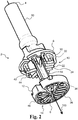
- Fig. 2 illustrates an exemplary filter device 2 prior to joining the first part 8 and the second part 12 to form the filter device 2 as illustrated in Fig. 1 .
- the filter device 2 comprises the first part 8 having a first filter structure 10 and the second part 12 having a second filter structure 14.
- the first part 8 comprises a tube part 50 with a cavity
- the second part 12 comprises a channel separator 54 with four inner walls extending inside the cavity along the center axis 100.
- the inner walls of the channel separator 54 extending inside the cavity form four channels including a first channel and a second channel.
- the first filter structure 10 comprises a first primary protruding member 22 having a distal end 24.
- the second filter structure comprises a first primary opening 26. After joining the first part 8 and the second part 12, the first primary protruding member 22 extends at least partly inside or through the first primary opening 26 along the center axis to form a primary first filter opening of the first set of filter openings for the first channel as illustrated in Fig. 1 .
- the first filter structure 10 comprises a plurality of protruding members, and the second filter structure 14 comprises a plurality of openings.
- the first filter structure 10 comprises a first secondary protruding member 30 having a distal end 32.
- the second filter structure comprises a first secondary opening 34. After joining the first part 8 and the second part 12, the first secondary protruding member 30 extends at least partly inside or through the first secondary opening 34 along the center axis to form a secondary first filter opening of the first set of filter openings for the first channel as illustrated in Fig. 1 .
- the first filter structure 10 comprises a second primary protruding member 42 having a distal end 44.
- the second filter structure comprises a second primary opening 46. After joining the first part 8 and the second part 12, the second primary protruding member 42 extends at least partly inside or through the second primary opening 46 along the center axis to form a primary second filter opening of the second set of filter openings for the second channel as illustrated in Fig. 1 .
- the protruding members of the first filter structure 10 such as the first primary protruding member 22, the first secondary protruding member 30, and/or the second primary protruding member 42 are configured to overlap along the center axis with their respective openings of the second filter structure, such as the first primary opening 26, the first secondary opening 34, and/or the second primary opening 46.
- the second part 12 may comprise one or more coupling parts for coupling a channel to a probe channel, e.g. the second part 12 may comprise a first coupling part for coupling the first channel to a probe channel and/or the second part 12 may comprise a second coupling part for coupling the second channel to a probe channel.
- the first coupling part may comprise a coupling ridge extending in the first direction and enclosing the first primary opening 26 and/or the first secondary opening 34.
- the second coupling part may comprise a coupling ridge extending in the first direction and enclosing the second primary opening 46.
- Fig. 3 illustrates a cross section of an exemplary filter device 2.
- the filter device 2 comprises a first channel 16 and a second channel 38.
- Fig. 3 furthermore illustrates the first part 8 comprising a tube part 50 having a cavity 52, and the second part 12 comprising a channel separator 54 extending inside the cavity 52 along the center axis 100.
- the channel separator 54 extending inside the cavity 52 forms the first channel 16 and the second channel 38.
- the first part 8 and the second part 12 are joined together to form a filter element 18 comprising a plurality of filter openings.
- the filter element 18 comprises a primary first filter opening 28 for the first channel 16.
- the primary first filter opening 28 may be part of a first set of filter openings for the first channel 16 as described in relation to Fig. 1 .
- Figs. 4a-4c are side views of an exemplary filter device 2, an exemplary first part 8, and an exemplary second part 12, respectively.
- Fig. 4a illustrates the filter device 2.
- Fig. 4b illustrates the first part 8 of the filter device 2.
- the first part 8 having a first filter structure 10.
- Fig. 4c illustrates the second part 12 of the filter device 2.
- the second part having a second filter structure 14.
- Fig. 4a illustrates the filter device 2 wherein the first part 8 and the second part 12 are joined together. Thereby, the first filter structure 10 and the second filter 14 structure define a filter element 18 of the filter device 2.
- the first part 8 comprises a tube part 50
- the second part 12 comprises a channel separator 54.
- the channel separator 54 After joining the first part 8 and the second part 12, the channel separator 54 extends inside a cavity of the tube part 50 along the center axis 100, forming a first channel and a second channel.
- the channel separator 54 may comprise a plurality of separator walls to form a plurality of channels, e.g. the channel separator 54 may comprise four separator walls to form a first channel, a second channel, a third channel, and a fourth channel.
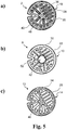
- Figs. 5a-5c illustrates an exemplary filter device 2, an exemplary first part 8, and an exemplary second part 12, respectively, shown from the second end 6 ( Fig. 1 ).
- Fig. 5a illustrates the filter device 2, wherein the filter element 18 comprises a first set of filter openings 20 for a first channel and a second set of filter openings 40 for a second channel.
- the first set of filter openings 20 comprises a primary first filter opening 28 and a secondary first filter opening 36.
- the second set of filter openings 40 comprises a primary second filter opening 48.
- Fig. 5b illustrates the first part 8 of the filter device 2.
- the first part 8 having a first filter structure 10.
- the first filter structure 10 comprises a plurality of protruding members, including a first primary protruding member 22, a first secondary protruding member 30, and a second primary protruding member 42. Also shown is the cavity 52 of a tube part of the first part 8.
- a protruding member such as the first primary protruding member 22, the first secondary protruding member 30, and/or the second primary protruding member 42, may have an oval or oblong cross-section.
- a protruding member, such as the first primary protruding member 22, the first secondary protruding member 30, and/or the second primary protruding member 42 may be circular, triangular and/or rectangular cross-section.
- Fig. 5c illustrates the second part 12 of the filter device 2.
- the second part having a second filter structure 14.
- the second filter structure 14 comprises a plurality of openings, including a first primary opening 26, a first secondary opening 34, and a second primary opening 46.
- the openings of the second filter structure 14, such as the first primary opening 26, the first secondary opening 34, and/or the second primary opening 46 are slightly bigger than their respective protruding member of the first filter structure 10, such as the first primary protruding member 22, the first secondary protruding member 30, and/or the second primary protruding member 42, e.g. an opening 26, 34, 46 has a cross-sectional area slightly bigger than its respective protruding member 22, 30, 42.
- a protruding member of the first filter structure 10 may comprise one or more support points including a first support point. After joining the first part 8 and the second part 12, the first support point may contact a first inner sidewall of an opening of the second filter structure 14, such as the first primary opening 26, the first secondary opening 34, and/or the second primary opening 46.
- the first filter structure 10 and the second filter structure 12 defines the filter element 18, as shown in Fig. 5a .
- the first primary protruding member 22 extends at least partly inside or through the first primary opening 26 to form the primary first filter opening 28.
- the first secondary protruding member 30 extends at least partly inside or through the first secondary opening 34 to form the secondary first filter opening 36.
- the second primary protruding member 42 extends at least partly inside or through the second primary opening 46 to form the primary second filter opening 48.
- Figs. 6a-6c illustrates an exemplary filter device 2, an exemplary first part 8, and an exemplary second part 12, respectively, shown from the first end 4 ( Fig. 1 ).
- Fig. 6a illustrates the filter device 2 comprising a first channel 16 and a second channel 38.
- Fig. 6b illustrates the first part 8 of the filter device 2.
- the first part 8 comprises a tube part 50 with a cavity 52.
- Fig. 6c illustrates the second part 12 of the filter device 2.
- the second part 12 comprises a channel separator 54.
- the filter device 2 After joining the first part 8 and the second part 12, the filter device 2 comprises a plurality of channels including the first channel 16 and a second channel 38, as shown in Fig. 6a .
- the first channel 16 and the second channel 38 are separated by the channel separator 54 extending inside the cavity 52 of the tube part 50.
- Fig. 7 illustrates an exemplary filter device 2, wherein the second part 12 comprises one or more coupling parts including a first coupling part 62.
- the second part 12 comprises a plurality of coupling parts including the first coupling part 62, a second coupling part 64, a third coupling part 66 and a fourth coupling part 68, for coupling respective channels and filter openings to respective probes/probe channels.
- the filter device may comprise a coupling member including the coupling part(s).
- the coupling member may be a separate member, e.g. made in a material different from the first and second parts.
- the first coupling part is configured for coupling the first channel to a probe channel and/or for coupling the filter device 2 to a probe.
- the plurality of coupling parts may be configured for coupling the plurality of channels of the filter device to a plurality of channels of the probe.
- a coupling part may comprise a coupling ridge extending in the first direction.
- the first coupling part 62 comprises a first coupling ridge 70 extending in the first direction..
- Fig. 8 is a flow diagram of an exemplary method 200 of manufacturing a filter device with a first channel.
- the method 200 comprises obtaining 202 a first part with a first filter structure, obtaining 204 a second part with a second filter structure, and joining 206 the first part and the second part.
- Joining 206 the first part and the second part comprises at least partly inserting the first filter structure into the second filter structure to form a filter element with a first set of filter openings for the first channel.
- the first part may comprise plastic molding of the first part and/or obtaining 204 the second part may comprise plastic molding of the second part.
- Joining 206 the first part and the second part may comprise ultrasonic welding of the first part and the second part.
- joining 206 the first part and the second part may comprise inserting the first filter structure into the second filter structure, and subsequently ultrasonic welding the first part and the second part.
Landscapes
- Health & Medical Sciences (AREA)
- Engineering & Computer Science (AREA)
- Life Sciences & Earth Sciences (AREA)
- Physics & Mathematics (AREA)
- General Health & Medical Sciences (AREA)
- Manufacturing & Machinery (AREA)
- Otolaryngology (AREA)
- Acoustics & Sound (AREA)
- Biomedical Technology (AREA)
- Molecular Biology (AREA)
- Biophysics (AREA)
- Pathology (AREA)
- Neurosurgery (AREA)
- Heart & Thoracic Surgery (AREA)
- Medical Informatics (AREA)
- Signal Processing (AREA)
- Surgery (AREA)
- Animal Behavior & Ethology (AREA)
- Public Health (AREA)
- Veterinary Medicine (AREA)
- Audiology, Speech & Language Pathology (AREA)
- Multimedia (AREA)
- Sampling And Sample Adjustment (AREA)
- Prostheses (AREA)
Claims (13)
- Filtervorrichtung (2) für eine Hörtestsonde, wobei sich die Filtervorrichtung (2) entlang einer Mittelachse (100) in einer ersten Richtung von einem ersten Ende (4) zu einem zweiten Ende (6) erstreckt und Folgendes umfasst:- einen ersten Teil (8) mit einer ersten Filterstruktur (10),- einen zweiten Teil (12) mit einer zweiten Filterstruktur (14),- einen ersten Kanal (16), der sich entlang der Mittelachse (100) erstreckt,wobei der erste Teil (8) und der zweite Teil (12) miteinander verbunden sind, und die erste Filterstruktur (10) und die zweite Filterstruktur (14) ein Filterelement (18) mit einem ersten Satz von Filteröffnungen (20) für den ersten Kanal (16) definieren, und wobei die erste Filterstruktur (10) ein erstes primäres vorspringendes Element (22) mit einem distalen Ende (24) umfasst, und wobei die zweite Filterstruktur (14) eine erste primäre Öffnung (26) umfasst,
wobei sich das erste primäre vorspringende Element (22) zumindest teilweise in der ersten primären Öffnung (26) entlang der Mittelachse (100) erstreckt, um eine primäre erste Filteröffnung (28) des ersten Satzes von Filteröffnungen (20) zu bilden,
dadurch gekennzeichnet, dass
die erste Filterstruktur (10) ein erstes sekundäres vorspringendes Element (30) umfasst, und die zweite Filterstruktur (14) eine erste sekundäre Öffnung (34) umfasst, wobei sich das erste sekundäre vorspringende Element (30) zumindest teilweise in der ersten sekundären Öffnung (34) entlang der Mittelachse (100) erstreckt, um eine sekundäre erste Filteröffnung (36) des ersten Satzes von Filteröffnungen (20) zu bilden. - Filtervorrichtung nach Anspruch 1, wobei das erste primäre vorspringende Element (22) einen kreisförmigen, ovalen, länglichen, dreieckigen oder rechteckigen Querschnitt aufweist.
- Filtervorrichtung nach einem der Ansprüche 1-2, wobei das erste primäre vorspringende Element (22) einen oder mehrere Unterstützungspunkte einschließlich eines ersten Unterstützungspunkts umfasst, und wobei der erste Unterstützungspunkt mit einer ersten inneren Seitenwand der ersten primären Öffnung (26) in der zweiten Filterstruktur (14) in Kontakt kommt.
- Filtervorrichtung nach einem der Ansprüche 1-3, wobei der zweite Teil (12) einen ersten Kupplungsteil (62) zur Kupplung des ersten Kanals (16) zu einem Sondenkanal umfasst, wobei der erste Kupplungsteil (62) eine Kupplungsrippe (70) umfasst, die sich in der ersten Richtung erstreckt und die erste primäre Öffnung (26) umgibt.
- Filtervorrichtung nach einem der Ansprüche 1-4, wobei der Querschnittsbereich des ersten primären vorspringenden Elements (22) gegen sein distales Ende (24) abnimmt.
- Filtervorrichtung nach einem der vorgehenden Ansprüche, wobei die Filtervorrichtung einen zweiten Kanal (38) umfasst, der sich entlang der Mittelachse (100) erstreckt, und wobei das Filterelement (18) einen zweiten Satz von Filteröffnungen (40) für den zweiten Kanal (38) aufweist.
- Filtervorrichtung nach Anspruch 6, wobei der erste Teil (8) einen Rohrteil (50) mit einem Hohlraum (52) umfasst, und der zweite Teil (12) einen Kanalseparator (54) umfasst, der sich innerhalb des Hohlraums (52) entlang der Mittelachse (100) erstreckt, um den ersten Kanal (16) und den zweiten Kanal (38) zu bilden.
- Filtervorrichtung nach einem der Ansprüche 6-7, wobei die erste Filterstruktur (10) ein zweites primäres vorspringendes Element (42) umfasst, und wobei die zweite Filterstruktur (14) eine zweite primäre Öffnung (46) umfasst, wobei sich das zweite primäre vorspringende Element (42) in der zweiten primären Öffnung (46) entlang der Mittelachse (100) erstreckt, um eine primäre zweite Filteröffnung (48) des zweiten Satzes von Filteröffnungen (40) zu bilden.
- Filtervorrichtung nach einem der vorgehenden Ansprüche, wobei der erste Teil (8) und/oder der zweite Teil (12) zumindest teilweise mit einer hydrophoben Substanz beschichtet ist.
- Hörtestsonde umfassend eine Filtervorrichtung nach einem der Ansprüche 1-9.
- Verfahren (200) zur Herstellung einer Filtervorrichtung mit einem ersten Kanal, welches Verfahren Folgendes umfasst:- Erhalten (202) eines ersten Teils mit einer ersten Filterstruktur, wobei die erste Filterstruktur ein erstes primäres vorspringendes Element mit einem distalen Ende umfasst, und die erste Filterstruktur ein erstes sekundäres vorspringendes Element umfasst;- Erhalten (204) eines zweiten Teils mit einer zweiten Filterstruktur, wobei die zweite Filterstruktur eine erste primäre Öffnung umfasst, und die zweite Filterstruktur eine erste sekundäre Öffnung umfasst; und- Verbinden (206) des ersten Teils und des zweiten Teils, wobei das Verbinden des ersten Teils und des zweiten Teils zumindest teilweise Einführung der ersten Filterstruktur in die zweite Filterstruktur umfasst, um ein Filterelement mit einem ersten Satz von Filteröffnungen für den ersten Kanal zu bilden, wobei sich das erste primäre vorspringende Element zumindest teilweise in der ersten primären Öffnung erstreckt, um eine primäre erste Filteröffnung des ersten Satzes von Filteröffnungen zu bilden, und wobei sich das erste sekundäre vorspringende Element zumindest teilweise in der ersten sekundären Öffnung erstreckt, um eine erste sekundäre Filteröffnung des ersten Satzes von Filteröffnungen zu bilden.
- Verfahren nach Anspruch 11, wobei das Erhalten (202) des ersten Teils mit der ersten Filterstruktur Kunststoffformen des ersten Teils umfasst.
- Verfahren nach einem der Ansprüche 11-12, wobei das Verbinden (206) Ultraschallschweißen des ersten Teils und des zweiten Teils umfasst.
Priority Applications (4)
| Application Number | Priority Date | Filing Date | Title |
|---|---|---|---|
| EP14200629.5A EP3040023B1 (de) | 2014-12-30 | 2014-12-30 | Filtervorrichtung und Verfahren zum Herstellen einer Filtervorrichtung |
| US14/590,459 US9629575B2 (en) | 2014-12-30 | 2015-01-06 | Filter device and method of manufacturing a filter device |
| JP2015249056A JP6596324B2 (ja) | 2014-12-30 | 2015-12-21 | フィルタデバイス |
| CN201511020527.1A CN105727636B (zh) | 2014-12-30 | 2015-12-30 | 过滤器装置及其制造方法 |
Applications Claiming Priority (1)
| Application Number | Priority Date | Filing Date | Title |
|---|---|---|---|
| EP14200629.5A EP3040023B1 (de) | 2014-12-30 | 2014-12-30 | Filtervorrichtung und Verfahren zum Herstellen einer Filtervorrichtung |
Publications (2)
| Publication Number | Publication Date |
|---|---|
| EP3040023A1 EP3040023A1 (de) | 2016-07-06 |
| EP3040023B1 true EP3040023B1 (de) | 2019-06-26 |
Family
ID=52278472
Family Applications (1)
| Application Number | Title | Priority Date | Filing Date |
|---|---|---|---|
| EP14200629.5A Not-in-force EP3040023B1 (de) | 2014-12-30 | 2014-12-30 | Filtervorrichtung und Verfahren zum Herstellen einer Filtervorrichtung |
Country Status (1)
| Country | Link |
|---|---|
| EP (1) | EP3040023B1 (de) |
Family Cites Families (2)
| Publication number | Priority date | Publication date | Assignee | Title |
|---|---|---|---|---|
| US7471800B2 (en) * | 2004-03-29 | 2008-12-30 | In'tech Industries, Inc. | Wax barrier system |
| US8885859B2 (en) * | 2010-07-16 | 2014-11-11 | Sonion Nederland Bv | Semi-permanent hearing aid |
-
2014
- 2014-12-30 EP EP14200629.5A patent/EP3040023B1/de not_active Not-in-force
Non-Patent Citations (1)
| Title |
|---|
| None * |
Also Published As
| Publication number | Publication date |
|---|---|
| EP3040023A1 (de) | 2016-07-06 |
Similar Documents
| Publication | Publication Date | Title |
|---|---|---|
| JP7198888B2 (ja) | ワイヤ状アタッチメント機構を介した結合用イヤチップ | |
| US10993010B2 (en) | Open-air earbuds and methods for making the same | |
| US9025807B2 (en) | Couplable hearing apparatus for a hearing device, coupling element and hearing device | |
| CN106256134A (zh) | 具有柔性翼片的听筒 | |
| US8750552B2 (en) | Multi-diameter speaker vent ports | |
| CN102014326A (zh) | 耳道式耳机 | |
| US20160277818A1 (en) | Portable communication device with flow through acoustic transducer ports for water management | |
| JP5894322B1 (ja) | 簡易型補聴器具 | |
| JP5747860B2 (ja) | イヤ−ピ−ス及びヘッドホン | |
| US9629575B2 (en) | Filter device and method of manufacturing a filter device | |
| US9456269B2 (en) | Plug earphone or a concha earphone | |
| US11950061B2 (en) | Hearing device cerumen filter device | |
| EP3040023A1 (de) | Filtervorrichtung und Verfahren zum Herstellen einer Filtervorrichtung | |
| US9004223B2 (en) | Conformable dome ear canal tip for a hearing instrument | |
| DK201470838A1 (en) | Filter device and method of manufacturing a filter device | |
| EP3718314B1 (de) | Cerumenschutzstopfen | |
| KR101485005B1 (ko) | 외부 음향의 유입이 가능한 이어팁 및 이를 갖는 이어폰 | |
| KR101601859B1 (ko) | 인 이어 이어폰 | |
| KR101063521B1 (ko) | 보청기 | |
| CN107079216A (zh) | 耳机系统 | |
| CN110505559A (zh) | 助听器扬声器的耳垢过滤器解决方案 |
Legal Events
| Date | Code | Title | Description |
|---|---|---|---|
| PUAI | Public reference made under article 153(3) epc to a published international application that has entered the european phase |
Free format text: ORIGINAL CODE: 0009012 |
|
| AK | Designated contracting states |
Kind code of ref document: A1 Designated state(s): AL AT BE BG CH CY CZ DE DK EE ES FI FR GB GR HR HU IE IS IT LI LT LU LV MC MK MT NL NO PL PT RO RS SE SI SK SM TR |
|
| AX | Request for extension of the european patent |
Extension state: BA ME |
|
| STAA | Information on the status of an ep patent application or granted ep patent |
Free format text: STATUS: REQUEST FOR EXAMINATION WAS MADE |
|
| 17P | Request for examination filed |
Effective date: 20170104 |
|
| RBV | Designated contracting states (corrected) |
Designated state(s): AL AT BE BG CH CY CZ DE DK EE ES FI FR GB GR HR HU IE IS IT LI LT LU LV MC MK MT NL NO PL PT RO RS SE SI SK SM TR |
|
| RAP1 | Party data changed (applicant data changed or rights of an application transferred) |
Owner name: NATUS MEDICAL INCORPORATED |
|
| RIC1 | Information provided on ipc code assigned before grant |
Ipc: A61B 5/12 20060101AFI20181218BHEP Ipc: A61B 5/00 20060101ALI20181218BHEP Ipc: H04R 25/00 20060101ALI20181218BHEP |
|
| GRAP | Despatch of communication of intention to grant a patent |
Free format text: ORIGINAL CODE: EPIDOSNIGR1 |
|
| STAA | Information on the status of an ep patent application or granted ep patent |
Free format text: STATUS: GRANT OF PATENT IS INTENDED |
|
| INTG | Intention to grant announced |
Effective date: 20190201 |
|
| GRAS | Grant fee paid |
Free format text: ORIGINAL CODE: EPIDOSNIGR3 |
|
| GRAA | (expected) grant |
Free format text: ORIGINAL CODE: 0009210 |
|
| STAA | Information on the status of an ep patent application or granted ep patent |
Free format text: STATUS: THE PATENT HAS BEEN GRANTED |
|
| AK | Designated contracting states |
Kind code of ref document: B1 Designated state(s): AL AT BE BG CH CY CZ DE DK EE ES FI FR GB GR HR HU IE IS IT LI LT LU LV MC MK MT NL NO PL PT RO RS SE SI SK SM TR |
|
| REG | Reference to a national code |
Ref country code: GB Ref legal event code: FG4D |
|
| REG | Reference to a national code |
Ref country code: CH Ref legal event code: EP |
|
| REG | Reference to a national code |
Ref country code: DE Ref legal event code: R096 Ref document number: 602014049010 Country of ref document: DE |
|
| REG | Reference to a national code |
Ref country code: AT Ref legal event code: REF Ref document number: 1147362 Country of ref document: AT Kind code of ref document: T Effective date: 20190715 |
|
| REG | Reference to a national code |
Ref country code: IE Ref legal event code: FG4D |
|
| REG | Reference to a national code |
Ref country code: NL Ref legal event code: MP Effective date: 20190626 |
|
| PG25 | Lapsed in a contracting state [announced via postgrant information from national office to epo] |
Ref country code: NO Free format text: LAPSE BECAUSE OF FAILURE TO SUBMIT A TRANSLATION OF THE DESCRIPTION OR TO PAY THE FEE WITHIN THE PRESCRIBED TIME-LIMIT Effective date: 20190926 Ref country code: AL Free format text: LAPSE BECAUSE OF FAILURE TO SUBMIT A TRANSLATION OF THE DESCRIPTION OR TO PAY THE FEE WITHIN THE PRESCRIBED TIME-LIMIT Effective date: 20190626 Ref country code: FI Free format text: LAPSE BECAUSE OF FAILURE TO SUBMIT A TRANSLATION OF THE DESCRIPTION OR TO PAY THE FEE WITHIN THE PRESCRIBED TIME-LIMIT Effective date: 20190626 Ref country code: SE Free format text: LAPSE BECAUSE OF FAILURE TO SUBMIT A TRANSLATION OF THE DESCRIPTION OR TO PAY THE FEE WITHIN THE PRESCRIBED TIME-LIMIT Effective date: 20190626 Ref country code: LT Free format text: LAPSE BECAUSE OF FAILURE TO SUBMIT A TRANSLATION OF THE DESCRIPTION OR TO PAY THE FEE WITHIN THE PRESCRIBED TIME-LIMIT Effective date: 20190626 Ref country code: HR Free format text: LAPSE BECAUSE OF FAILURE TO SUBMIT A TRANSLATION OF THE DESCRIPTION OR TO PAY THE FEE WITHIN THE PRESCRIBED TIME-LIMIT Effective date: 20190626 |
|
| REG | Reference to a national code |
Ref country code: LT Ref legal event code: MG4D |
|
| PG25 | Lapsed in a contracting state [announced via postgrant information from national office to epo] |
Ref country code: RS Free format text: LAPSE BECAUSE OF FAILURE TO SUBMIT A TRANSLATION OF THE DESCRIPTION OR TO PAY THE FEE WITHIN THE PRESCRIBED TIME-LIMIT Effective date: 20190626 Ref country code: BG Free format text: LAPSE BECAUSE OF FAILURE TO SUBMIT A TRANSLATION OF THE DESCRIPTION OR TO PAY THE FEE WITHIN THE PRESCRIBED TIME-LIMIT Effective date: 20190926 Ref country code: LV Free format text: LAPSE BECAUSE OF FAILURE TO SUBMIT A TRANSLATION OF THE DESCRIPTION OR TO PAY THE FEE WITHIN THE PRESCRIBED TIME-LIMIT Effective date: 20190626 Ref country code: GR Free format text: LAPSE BECAUSE OF FAILURE TO SUBMIT A TRANSLATION OF THE DESCRIPTION OR TO PAY THE FEE WITHIN THE PRESCRIBED TIME-LIMIT Effective date: 20190927 |
|
| REG | Reference to a national code |
Ref country code: AT Ref legal event code: MK05 Ref document number: 1147362 Country of ref document: AT Kind code of ref document: T Effective date: 20190626 |
|
| PG25 | Lapsed in a contracting state [announced via postgrant information from national office to epo] |
Ref country code: RO Free format text: LAPSE BECAUSE OF FAILURE TO SUBMIT A TRANSLATION OF THE DESCRIPTION OR TO PAY THE FEE WITHIN THE PRESCRIBED TIME-LIMIT Effective date: 20190626 Ref country code: SK Free format text: LAPSE BECAUSE OF FAILURE TO SUBMIT A TRANSLATION OF THE DESCRIPTION OR TO PAY THE FEE WITHIN THE PRESCRIBED TIME-LIMIT Effective date: 20190626 Ref country code: CZ Free format text: LAPSE BECAUSE OF FAILURE TO SUBMIT A TRANSLATION OF THE DESCRIPTION OR TO PAY THE FEE WITHIN THE PRESCRIBED TIME-LIMIT Effective date: 20190626 Ref country code: EE Free format text: LAPSE BECAUSE OF FAILURE TO SUBMIT A TRANSLATION OF THE DESCRIPTION OR TO PAY THE FEE WITHIN THE PRESCRIBED TIME-LIMIT Effective date: 20190626 Ref country code: AT Free format text: LAPSE BECAUSE OF FAILURE TO SUBMIT A TRANSLATION OF THE DESCRIPTION OR TO PAY THE FEE WITHIN THE PRESCRIBED TIME-LIMIT Effective date: 20190626 Ref country code: NL Free format text: LAPSE BECAUSE OF FAILURE TO SUBMIT A TRANSLATION OF THE DESCRIPTION OR TO PAY THE FEE WITHIN THE PRESCRIBED TIME-LIMIT Effective date: 20190626 Ref country code: PT Free format text: LAPSE BECAUSE OF FAILURE TO SUBMIT A TRANSLATION OF THE DESCRIPTION OR TO PAY THE FEE WITHIN THE PRESCRIBED TIME-LIMIT Effective date: 20191028 |
|
| PG25 | Lapsed in a contracting state [announced via postgrant information from national office to epo] |
Ref country code: IT Free format text: LAPSE BECAUSE OF FAILURE TO SUBMIT A TRANSLATION OF THE DESCRIPTION OR TO PAY THE FEE WITHIN THE PRESCRIBED TIME-LIMIT Effective date: 20190626 Ref country code: SM Free format text: LAPSE BECAUSE OF FAILURE TO SUBMIT A TRANSLATION OF THE DESCRIPTION OR TO PAY THE FEE WITHIN THE PRESCRIBED TIME-LIMIT Effective date: 20190626 Ref country code: IS Free format text: LAPSE BECAUSE OF FAILURE TO SUBMIT A TRANSLATION OF THE DESCRIPTION OR TO PAY THE FEE WITHIN THE PRESCRIBED TIME-LIMIT Effective date: 20191026 Ref country code: ES Free format text: LAPSE BECAUSE OF FAILURE TO SUBMIT A TRANSLATION OF THE DESCRIPTION OR TO PAY THE FEE WITHIN THE PRESCRIBED TIME-LIMIT Effective date: 20190626 |
|
| PG25 | Lapsed in a contracting state [announced via postgrant information from national office to epo] |
Ref country code: TR Free format text: LAPSE BECAUSE OF FAILURE TO SUBMIT A TRANSLATION OF THE DESCRIPTION OR TO PAY THE FEE WITHIN THE PRESCRIBED TIME-LIMIT Effective date: 20190626 |
|
| PG25 | Lapsed in a contracting state [announced via postgrant information from national office to epo] |
Ref country code: PL Free format text: LAPSE BECAUSE OF FAILURE TO SUBMIT A TRANSLATION OF THE DESCRIPTION OR TO PAY THE FEE WITHIN THE PRESCRIBED TIME-LIMIT Effective date: 20190626 Ref country code: DK Free format text: LAPSE BECAUSE OF FAILURE TO SUBMIT A TRANSLATION OF THE DESCRIPTION OR TO PAY THE FEE WITHIN THE PRESCRIBED TIME-LIMIT Effective date: 20190626 |
|
| PG25 | Lapsed in a contracting state [announced via postgrant information from national office to epo] |
Ref country code: IS Free format text: LAPSE BECAUSE OF FAILURE TO SUBMIT A TRANSLATION OF THE DESCRIPTION OR TO PAY THE FEE WITHIN THE PRESCRIBED TIME-LIMIT Effective date: 20200224 |
|
| REG | Reference to a national code |
Ref country code: DE Ref legal event code: R097 Ref document number: 602014049010 Country of ref document: DE |
|
| PLBE | No opposition filed within time limit |
Free format text: ORIGINAL CODE: 0009261 |
|
| STAA | Information on the status of an ep patent application or granted ep patent |
Free format text: STATUS: NO OPPOSITION FILED WITHIN TIME LIMIT |
|
| PG2D | Information on lapse in contracting state deleted |
Ref country code: IS |
|
| REG | Reference to a national code |
Ref country code: CH Ref legal event code: PL |
|
| 26N | No opposition filed |
Effective date: 20200603 |
|
| REG | Reference to a national code |
Ref country code: BE Ref legal event code: MM Effective date: 20191231 |
|
| PG25 | Lapsed in a contracting state [announced via postgrant information from national office to epo] |
Ref country code: MC Free format text: LAPSE BECAUSE OF FAILURE TO SUBMIT A TRANSLATION OF THE DESCRIPTION OR TO PAY THE FEE WITHIN THE PRESCRIBED TIME-LIMIT Effective date: 20190626 Ref country code: SI Free format text: LAPSE BECAUSE OF FAILURE TO SUBMIT A TRANSLATION OF THE DESCRIPTION OR TO PAY THE FEE WITHIN THE PRESCRIBED TIME-LIMIT Effective date: 20190626 |
|
| PG25 | Lapsed in a contracting state [announced via postgrant information from national office to epo] |
Ref country code: IE Free format text: LAPSE BECAUSE OF NON-PAYMENT OF DUE FEES Effective date: 20191230 Ref country code: LU Free format text: LAPSE BECAUSE OF NON-PAYMENT OF DUE FEES Effective date: 20191230 |
|
| PG25 | Lapsed in a contracting state [announced via postgrant information from national office to epo] |
Ref country code: LI Free format text: LAPSE BECAUSE OF NON-PAYMENT OF DUE FEES Effective date: 20191231 Ref country code: CH Free format text: LAPSE BECAUSE OF NON-PAYMENT OF DUE FEES Effective date: 20191231 Ref country code: BE Free format text: LAPSE BECAUSE OF NON-PAYMENT OF DUE FEES Effective date: 20191231 |
|
| PG25 | Lapsed in a contracting state [announced via postgrant information from national office to epo] |
Ref country code: CY Free format text: LAPSE BECAUSE OF FAILURE TO SUBMIT A TRANSLATION OF THE DESCRIPTION OR TO PAY THE FEE WITHIN THE PRESCRIBED TIME-LIMIT Effective date: 20190626 |
|
| PG25 | Lapsed in a contracting state [announced via postgrant information from national office to epo] |
Ref country code: HU Free format text: LAPSE BECAUSE OF FAILURE TO SUBMIT A TRANSLATION OF THE DESCRIPTION OR TO PAY THE FEE WITHIN THE PRESCRIBED TIME-LIMIT; INVALID AB INITIO Effective date: 20141230 Ref country code: MT Free format text: LAPSE BECAUSE OF FAILURE TO SUBMIT A TRANSLATION OF THE DESCRIPTION OR TO PAY THE FEE WITHIN THE PRESCRIBED TIME-LIMIT Effective date: 20190626 |
|
| PGFP | Annual fee paid to national office [announced via postgrant information from national office to epo] |
Ref country code: GB Payment date: 20211101 Year of fee payment: 8 Ref country code: FR Payment date: 20211101 Year of fee payment: 8 |
|
| PGFP | Annual fee paid to national office [announced via postgrant information from national office to epo] |
Ref country code: DE Payment date: 20211222 Year of fee payment: 8 |
|
| PG25 | Lapsed in a contracting state [announced via postgrant information from national office to epo] |
Ref country code: MK Free format text: LAPSE BECAUSE OF FAILURE TO SUBMIT A TRANSLATION OF THE DESCRIPTION OR TO PAY THE FEE WITHIN THE PRESCRIBED TIME-LIMIT Effective date: 20190626 |
|
| REG | Reference to a national code |
Ref country code: DE Ref legal event code: R119 Ref document number: 602014049010 Country of ref document: DE |
|
| P01 | Opt-out of the competence of the unified patent court (upc) registered |
Effective date: 20230530 |
|
| GBPC | Gb: european patent ceased through non-payment of renewal fee |
Effective date: 20221230 |
|
| PG25 | Lapsed in a contracting state [announced via postgrant information from national office to epo] |
Ref country code: GB Free format text: LAPSE BECAUSE OF NON-PAYMENT OF DUE FEES Effective date: 20221230 Ref country code: DE Free format text: LAPSE BECAUSE OF NON-PAYMENT OF DUE FEES Effective date: 20230701 |
|
| PG25 | Lapsed in a contracting state [announced via postgrant information from national office to epo] |
Ref country code: FR Free format text: LAPSE BECAUSE OF NON-PAYMENT OF DUE FEES Effective date: 20221231 |