EP3040041A2 - Instrument électrochirurgical avec un ensemble de déploiement actionné pour déplacer un membre alimentable en énergie - Google Patents
Instrument électrochirurgical avec un ensemble de déploiement actionné pour déplacer un membre alimentable en énergie Download PDFInfo
- Publication number
- EP3040041A2 EP3040041A2 EP15191274.8A EP15191274A EP3040041A2 EP 3040041 A2 EP3040041 A2 EP 3040041A2 EP 15191274 A EP15191274 A EP 15191274A EP 3040041 A2 EP3040041 A2 EP 3040041A2
- Authority
- EP
- European Patent Office
- Prior art keywords
- assembly
- housing
- actuator
- energizable member
- deployment assembly
- Prior art date
- Legal status (The legal status is an assumption and is not a legal conclusion. Google has not performed a legal analysis and makes no representation as to the accuracy of the status listed.)
- Granted
Links
Images



Classifications
-
- A—HUMAN NECESSITIES
- A61—MEDICAL OR VETERINARY SCIENCE; HYGIENE
- A61B—DIAGNOSIS; SURGERY; IDENTIFICATION
- A61B18/00—Surgical instruments, devices or methods for transferring non-mechanical forms of energy to or from the body
- A61B18/04—Surgical instruments, devices or methods for transferring non-mechanical forms of energy to or from the body by heating
- A61B18/12—Surgical instruments, devices or methods for transferring non-mechanical forms of energy to or from the body by heating by passing a current through the tissue to be heated, e.g. high-frequency current
- A61B18/14—Probes or electrodes therefor
- A61B18/1442—Probes having pivoting end effectors, e.g. forceps
- A61B18/1445—Probes having pivoting end effectors, e.g. forceps at the distal end of a shaft, e.g. forceps or scissors at the end of a rigid rod
-
- A—HUMAN NECESSITIES
- A61—MEDICAL OR VETERINARY SCIENCE; HYGIENE
- A61B—DIAGNOSIS; SURGERY; IDENTIFICATION
- A61B17/00—Surgical instruments, devices or methods
- A61B2017/00681—Aspects not otherwise provided for
- A61B2017/00734—Aspects not otherwise provided for battery operated
-
- A—HUMAN NECESSITIES
- A61—MEDICAL OR VETERINARY SCIENCE; HYGIENE
- A61B—DIAGNOSIS; SURGERY; IDENTIFICATION
- A61B17/00—Surgical instruments, devices or methods
- A61B17/28—Surgical forceps
- A61B17/29—Forceps for use in minimally invasive surgery
- A61B17/2909—Handles
- A61B2017/2912—Handles transmission of forces to actuating rod or piston
-
- A—HUMAN NECESSITIES
- A61—MEDICAL OR VETERINARY SCIENCE; HYGIENE
- A61B—DIAGNOSIS; SURGERY; IDENTIFICATION
- A61B18/00—Surgical instruments, devices or methods for transferring non-mechanical forms of energy to or from the body
- A61B2018/00053—Mechanical features of the instrument of device
- A61B2018/00172—Connectors and adapters therefor
- A61B2018/00178—Electrical connectors
-
- A—HUMAN NECESSITIES
- A61—MEDICAL OR VETERINARY SCIENCE; HYGIENE
- A61B—DIAGNOSIS; SURGERY; IDENTIFICATION
- A61B18/00—Surgical instruments, devices or methods for transferring non-mechanical forms of energy to or from the body
- A61B2018/00053—Mechanical features of the instrument of device
- A61B2018/00184—Moving parts
- A61B2018/00196—Moving parts reciprocating lengthwise
-
- A—HUMAN NECESSITIES
- A61—MEDICAL OR VETERINARY SCIENCE; HYGIENE
- A61B—DIAGNOSIS; SURGERY; IDENTIFICATION
- A61B18/00—Surgical instruments, devices or methods for transferring non-mechanical forms of energy to or from the body
- A61B2018/00571—Surgical instruments, devices or methods for transferring non-mechanical forms of energy to or from the body for achieving a particular surgical effect
- A61B2018/00607—Coagulation and cutting with the same instrument
-
- A—HUMAN NECESSITIES
- A61—MEDICAL OR VETERINARY SCIENCE; HYGIENE
- A61B—DIAGNOSIS; SURGERY; IDENTIFICATION
- A61B18/00—Surgical instruments, devices or methods for transferring non-mechanical forms of energy to or from the body
- A61B18/04—Surgical instruments, devices or methods for transferring non-mechanical forms of energy to or from the body by heating
- A61B18/12—Surgical instruments, devices or methods for transferring non-mechanical forms of energy to or from the body by heating by passing a current through the tissue to be heated, e.g. high-frequency current
- A61B18/1206—Generators therefor
- A61B2018/1246—Generators therefor characterised by the output polarity
- A61B2018/1253—Generators therefor characterised by the output polarity monopolar
-
- A—HUMAN NECESSITIES
- A61—MEDICAL OR VETERINARY SCIENCE; HYGIENE
- A61B—DIAGNOSIS; SURGERY; IDENTIFICATION
- A61B18/00—Surgical instruments, devices or methods for transferring non-mechanical forms of energy to or from the body
- A61B18/04—Surgical instruments, devices or methods for transferring non-mechanical forms of energy to or from the body by heating
- A61B18/12—Surgical instruments, devices or methods for transferring non-mechanical forms of energy to or from the body by heating by passing a current through the tissue to be heated, e.g. high-frequency current
- A61B18/1206—Generators therefor
- A61B2018/1246—Generators therefor characterised by the output polarity
- A61B2018/126—Generators therefor characterised by the output polarity bipolar
-
- A—HUMAN NECESSITIES
- A61—MEDICAL OR VETERINARY SCIENCE; HYGIENE
- A61B—DIAGNOSIS; SURGERY; IDENTIFICATION
- A61B18/00—Surgical instruments, devices or methods for transferring non-mechanical forms of energy to or from the body
- A61B18/04—Surgical instruments, devices or methods for transferring non-mechanical forms of energy to or from the body by heating
- A61B18/12—Surgical instruments, devices or methods for transferring non-mechanical forms of energy to or from the body by heating by passing a current through the tissue to be heated, e.g. high-frequency current
- A61B18/14—Probes or electrodes therefor
- A61B2018/1405—Electrodes having a specific shape
- A61B2018/1422—Hook
-
- A—HUMAN NECESSITIES
- A61—MEDICAL OR VETERINARY SCIENCE; HYGIENE
- A61B—DIAGNOSIS; SURGERY; IDENTIFICATION
- A61B18/00—Surgical instruments, devices or methods for transferring non-mechanical forms of energy to or from the body
- A61B18/04—Surgical instruments, devices or methods for transferring non-mechanical forms of energy to or from the body by heating
- A61B18/12—Surgical instruments, devices or methods for transferring non-mechanical forms of energy to or from the body by heating by passing a current through the tissue to be heated, e.g. high-frequency current
- A61B18/14—Probes or electrodes therefor
- A61B18/1442—Probes having pivoting end effectors, e.g. forceps
- A61B2018/1452—Probes having pivoting end effectors, e.g. forceps including means for cutting
- A61B2018/1455—Probes having pivoting end effectors, e.g. forceps including means for cutting having a moving blade for cutting tissue grasped by the jaws
-
- A—HUMAN NECESSITIES
- A61—MEDICAL OR VETERINARY SCIENCE; HYGIENE
- A61B—DIAGNOSIS; SURGERY; IDENTIFICATION
- A61B18/00—Surgical instruments, devices or methods for transferring non-mechanical forms of energy to or from the body
- A61B18/04—Surgical instruments, devices or methods for transferring non-mechanical forms of energy to or from the body by heating
- A61B18/12—Surgical instruments, devices or methods for transferring non-mechanical forms of energy to or from the body by heating by passing a current through the tissue to be heated, e.g. high-frequency current
- A61B18/14—Probes or electrodes therefor
- A61B2018/1467—Probes or electrodes therefor using more than two electrodes on a single probe
Definitions
- the present disclosure relates to surgical instruments and, more particularly, to multi-function surgical instruments capable of operating in both a bipolar mode and a monopolar mode.
- Bipolar surgical instruments e.g., bipolar electrosurgical forceps
- Bipolar electrosurgical forceps typically include two generally opposing electrodes charged to different electrical potentials for conducting energy therebetween and through tissue.
- Bipolar electrosurgical forceps utilize both mechanical clamping action and electrical energy to effect hemostasis by heating tissue and blood vessels to coagulate and/or cauterize tissue.
- Certain surgical procedures require more than simply cauterizing tissue and rely on the unique combination of clamping pressure, precise electrosurgical energy control and gap distance (i.e., distance between opposing jaw members when closed about tissue) to "seal" tissue.
- Monopolar surgical instruments include an active electrode, and are used in conjunction with a remote return electrode, e.g., a return pad, to apply energy to tissue.
- Monopolar instruments have the ability to rapidly move through tissue and dissect through narrow tissue planes.
- bipolar and monopolar instrumentation e.g., procedures where it is necessary to dissect through one or more layers of tissue in order to reach underlying tissue(s) to be sealed.
- distal refers to the portion that is being described that is further from a user
- proximal refers to the portion that is being described that is closer to a user
- a surgical instrument including a housing, an energizable member, a powered deployment assembly, and a cable assembly.
- the energizable member is configured to supply electrosurgical energy to tissue, and is movable between a storage position and a deployed position.
- the powered deployment assembly is configured to selectively move the energizable member between the storage position and the deployed position.
- the cable assembly having a cable coupled to the housing at a first end and having a plug coupled to the cable at a second, opposite end.
- the cable housing one or more first wires for selectively providing electrosurgical energy to the energizable member and one or more second wires for selectively providing power to the powered deployment assembly.
- the plug is configured to house a battery therein for powering the powered deployment assembly via the one or more second wires.
- the energizable member is coupled to an actuator disposed in the powered deployment assembly such that selective actuation of the actuator moves the energizable member between the storage position and the deployed position.
- the actuator includes a ferromagnetic material and wherein the powered deployment assembly further includes a magnet configured to actuate the actuator.
- the magnet is an electromagnet and wherein the energy source in the plug is configured to selectively produce a magnetic field around at least a portion of the electromagnet.
- the powered deployment assembly includes a guide extending between a proximal portion and a distal portion thereof, the magnet being fixed to the distal portion and the actuator being slidably disposed on the proximal portion.
- the powered deployment assembly further includes a biasing member disposed between the magnet and the actuator, the biasing member configured to bias the magnet away from the actuator.
- the surgical instrument further including a switch assembly operably coupled to the powered deployment assembly and to a source of electrosurgical energy such that when the switch is activated electrosurgical energy is supplied to the energizable member when the energizable member is in the deployed position.
- the powered deployment assembly includes a motor configured to drive movement of the energizable member between the storage position and the deployed position.
- Another surgical instrument includes a housing, an energizable member, a powered deployment assembly, and a switch assembly.
- the energizable member is configured to supply electrosurgical energy to tissue and is movable relative to the housing between a storage position and a deployed position.
- the powered deployment assembly is configured to selectively translate the energizable member between the storage position and the deployed position.
- the powered deployment assembly includes an electromagnet disposed in the housing and configured to be selectively energizable, an actuator disposed in the housing and movable along an axis between a proximal position and a distal position, the actuator being operably coupled to the energizable member, and a biasing member disposed between the electromagnet and the actuator to biased the electromagnet and actuator apart from one another. Energizing the electromagnet moves the actuator distally towards the electromagnet, thereby translating the energizable member to the deployed position.
- the switch assembly is disposed on the housing and is operably coupled to the powered deployment assembly for selectively energizing the electromagnet.
- the powered deployment assembly includes a guide extending between a proximal portion and a distal portion thereof, the electromagnet being fixed to the distal portion and the actuator being slidably disposed on the proximal portion.
- the guide includes at least one stopper, the at least one stopper configured to provide for controlled linear motion of the actuator.
- a cable assembly is coupled to the housing at a first end, and has a plug at a second, opposite end, the plug adapted to connect to an energy source for powering the powered deployment assembly.
- the plug houses a battery for powering the powered deployment assembly.
- the switch assembly includes at least one sensor, the at least one sensor adapted to communicate with a source of electrosurgical energy to selectively supply electrosurgical energy to the energizable member when the energizable member is in the deployed position.
- a surgical system including a surgical instrument and an electrosurgical generator.
- the surgical instrument includes a housing, an energizable member, a powered deployment assembly, and a cable assembly.
- the energizable member is configured to supply electrosurgical energy to tissue, and is movable between a storage position and a deployed position.
- the powered deployment assembly is configured to selectively move the energizable member between the storage position and the deployed position.
- the cable assembly having a cable coupled to the housing at a first end and having a plug coupled to the cable at a second, opposite end.
- the cable housing one or more first wires for selectively providing electrosurgical energy to the energizable member and one or more second wires for selectively providing power to the powered deployment assembly.
- the plug is configured to house a battery therein for powering the powered deployment assembly via the one or more second wires.
- the electrosurgical generator is configured to generate electrosurgical energy, wherein the plug is operably coupled to the electrosurgical generator to selectively supply electrosurgical energy to the energizable member.
- the plug defines a plug housing configured to house the battery.
- the plug housing includes a housing door for selectively enclosing the batteryinside the plug.
- the battery is selectively replaceable.
- the battery is a 9V battery, although other suitable batteries or energy sources are also contemplated.
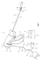
- a forceps 10 is provided in accordance with the present disclosure.
- the forceps 10 is configured to operate in both a bipolar mode, e.g., for grasping, treating, and/or dissecting tissue, and a monopolar mode, e.g., for treating and/or dissecting tissue.
- a bipolar mode e.g., for grasping, treating, and/or dissecting tissue
- a monopolar mode e.g., for treating and/or dissecting tissue.
- the forceps 10 includes a housing 20, a handle assembly 30, a trigger assembly 60, a rotating assembly 70, a powered deployment assembly 80 ( Figs. 3 and 4 ), a cable assembly 90, an end effector assembly 100, and a monopolar assembly 200.
- Forceps 10 further includes a shaft 12 having a distal end 12b configured to mechanically engage end effector assembly 100 and a proximal end 12a that mechanically engages housing 20.
- the forceps 10 is operably coupled to a source of electrosurgical energy, such as, for example, an electrosurgical generator "G," using a cable 92 of the cable assembly 90.
- Cable 92 includes a first end 92a coupled to housing 20 and a bifurcated second, opposite end 92b coupled to a plug assembly having a monopolar plug 50 and a bipolar plug 150.
- Monopolar plug 50 is configured to releasably couple to a monopolar input 2 of generator "G”
- bipolar plug 150 is configured to releasably couple to a bipolar input 152 of generator “G.”
- Cable 92 includes wires (not shown) extending therethrough that have sufficient length to extend through the shaft 12 in order to provide electrical energy to end effector assembly 100, e.g., upon activation of bipolar activation switch 4a.
- One or more of the wires (not shown) of cable 92 extends through housing 20 in order to provide electrical energy to monopolar assembly 200, e.g., upon activation of monopolar activation switch 4b.
- the forceps 10 may be energized using other suitable power sources.
- the forceps 10 may alternatively be configured as a battery-powered instrument.
- rotating assembly 70 is rotatable in either direction to rotate end effector assembly 100 and monopolar assembly 200 relative to housing 20.
- Housing 20 houses the internal working components of forceps 10.
- end effector assembly 100 is attached at the distal end 12b of shaft 12 and includes a first jaw member 110 and an opposing second jaw member 120 pivotably coupled to one another.
- Each of the jaw members 110, 120 respectively includes a first jaw body 111 and a second jaw body 121 supporting a respective first electrically-conductive surface 112 and a second electrically-conductive surface 122, and a respective first proximally-extending jaw flange 114 and a second proximally-extending jaw flange 124.
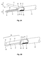
- Flanges 114, 124 are pivotably coupled to one another to permit movement of jaw members 110, 120 relative to one another between a spaced-apart position ( Fig. 2A ) and an approximated position ( Fig.
- end effector assembly 100 defines a bipolar configuration wherein electrically-conductive surface 112 is charged to a first electrical potential and electrically-conductive surface 122 is charged to a second, different electrical potential such that an electrical potential gradient is created for conducting energy between electrically-conductive surfaces 112, 122 and through tissue grasped therebetween for treating e.g., sealing, tissue.
- Bipolar activation switch 4a ( Fig. 1 ) is operably coupled between electrosurgical generator “G” and electrically-conductive surfaces 112, 122, thus allowing the user to selectively apply energy to electrically-conductive surfaces 112, 122 of jaw members 110, 120, respectively, of end effector assembly 100.
- End effector assembly 100 is designed as a unilateral assembly, i.e., where jaw member 120 is fixed relative to shaft 12 and jaw member 110 is movable relative to shaft 12 and fixed jaw member 120.
- end effector assembly 100 may alternatively be configured as a bilateral assembly, i.e., where both jaw member 110 and jaw member 120 are movable relative to one another and to shaft 12.
- a knife channel 125 may be defined within one or both of jaw members 110, 120 to permit reciprocation of a knife (not shown) therethrough, e.g., upon actuation of a trigger 62 of trigger assembly 60, to cut tissue grasped between jaw members 110, 120.
- monopolar assembly 200 includes an insulative sleeve 210, and an energizable member 220.
- Insulative sleeve 210 extends from the powered deployment assembly 80 ( Figs. 3-4 ), is slidably disposed about shaft 12, and is selectively movable about and relative to shaft 12 and end effector assembly 100 between a storage position ( Figs. 2A and 2B ), wherein insulative sleeve 210 is disposed proximally of end effector assembly 100, and a deployed position ( Fig. 2D ), wherein insulative sleeve 210 is substantially disposed about end effector 100 so as to electrically insulate electrically-conductive surfaces 112, 122 of jaw members 110, 120, respectively.
- Energizable member 220 extends from the powered deployment assembly 80 ( Figs. 3-4 ), through sleeve 210, and distally therefrom, ultimately defining an electrically-conductive tip 224.
- the one or more wires (not shown) extending from cable 92 through housing 20 ( Fig. 1 ), are coupled to energizable member 220 to provide energy to energizable member 220, e.g., upon actuation of monopolar activation switch 4b ( Fig. 1 ), for treating tissue in a monopolar mode of operation.
- Energizable member 220 is movable between a storage position ( Fig. 2B ) and a deployed position ( Fig. 2D ).
- electrically-conductive tip 224 of energizable member 220 is disposed within an insulated groove 126 defined within proximal flange 124 of jaw member 120, although other configurations are also contemplated.
- Insulated groove 126 electrically-insulates electrically-conductive tip 224 of energizable member 220 from electrically-conductive surfaces 112, 122 of jaw members 110, 120, respectively, and from surrounding tissue when disposed in the storage position.
- electrically-conductive tip 224 of energizable member 220 may only be insulated from surface 112. In such configurations, electrically-conductive tip 224 of energizable member 220 is capable of being energized to the same polarity as electrically-conductive surface 122.
- electrically-conductive tip 224 of energizable member 220 of monopolar assembly 200 extends distally from end effector assembly 100 while insulative sleeve 210 substantially surrounds end effector assembly 100.
- energy may be applied to electrically-conductive tip 224 of energizable member 220 to treat tissue, e.g., via activation of monopolar activation switch 4b ( Fig. 1 ).
- Electrically-conductive tip 224 may be hook-shaped (as shown), or may define any other suitable configuration, e.g., linear, ball, circular, angled, etc.
- both insulative sleeve 210 and energizable member 220 are coupled to powered deployment assembly 80.
- Powered deployment assembly 80 is selectively actuatable to transition monopolar assembly 200 between its storage position ( Figs. 2A and 2B ) and its deployed position ( Fig. 2D ). That is, powered deployment assembly 80 moves insulative sleeve 210 and energizable member 220 in conjunction with one another between their respective storage positions (collectively the storage position of monopolar assembly 200) and their respective deployed positions (collectively the deployed position of monopolar assembly 200).
- handle assembly 30 includes a movable handle 32 and a fixed handle 34.
- Fixed handle 34 is integrally associated with housing 20 and movable handle 32 is movable relative to fixed handle 34.
- Movable handle 32 is movable relative to fixed handle 34 between an initial position, wherein movable handle 32 is spaced from fixed handle 34, and a compressed position, wherein movable handle 32 is compressed towards fixed handle 34.
- a biasing member (not shown) may be provided to bias movable handle 32 towards the initial position.
- Movable handle 32 is ultimately connected to a drive assembly (not shown) disposed within housing 20 that, together, mechanically cooperate to impart movement of jaw members 110, 120 between the spaced-apart position ( Fig. 2A ), corresponding to the initial position of movable handle 32, and the approximated position ( Fig. 2B ), corresponding to the compressed position of movable handle 32.
- Any suitable drive assembly for this purpose may be provided.
- Trigger assembly 60 includes trigger 62 that is operably coupled to a knife (not shown). Trigger 62 of trigger assembly 60 is selectively actuatable to advance the knife from a retracted position, wherein the knife is disposed proximally of jaw members 110, 120, to an extended position, wherein the knife extends at least partially between jaw members 110, 120 and through knife channel 125 ( Fig. 2A ) to cut tissue grasped between jaw members 110, 120.
- the powered deployment assembly 80 is configured for selectively transition monopolar assembly 200 between the storage position and the deployed position by translating insulative sleeve 210 and energizable member 220 in conjunction with one another (though not necessarily the same distance or simultaneously) between their respective storage positions and their respective deployed position.
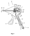
- Powered deployment assembly 80 in one embodiment, includes a magnet, such as, for example, an electromagnet 82, an actuator 84, a guide 86, and a biasing member 88.
- Guide 86 extends longitudinally between a proximal portion 86a and a distal portion 86b and is configured to maintain the trajectory of actuator 84 parallel to or coaxial with a longitudinal axis.
- electromagnet 82 is fixed to distal portion 86b and actuator 84 is slidingly disposed on proximal portion 86a.
- Other powered deployment assemblies are also contemplated, such powered deployment assembly 180 detailed below with respect to Fig. 5 .
- actuator 84 is coupled to insulative sleeve 210 and energizable member 220. As such, the distal translation of actuator 84 distally translates insulative sleeve 210 and energizable member 220. Similarly, the proximal translation of actuator 84 proximally translates insulative sleeve 210 and energizable member 220.
- actuator 84 is adjacent proximal portion 86a of guide 86, monopolar assembly 200 is in the storage position ( Figs. 2A and 2B ).
- actuator 84 is adjacent distal portion 86b of guide 86, monopolar assembly 200 is in the deployed position ( Fig. 2D ).
- Electromagnet 82 is coupled to monopolar activation switch 4b by way of a deployment circuit "DC" powered via an energy source, e.g., battery 56, electrosurgical generator “G,” a standard wall outlet (not shown), etc.
- a deployment circuit "DC” powered via an energy source, e.g., battery 56, electrosurgical generator “G,” a standard wall outlet (not shown), etc.
- energy source e.g., battery 56, electrosurgical generator “G,” a standard wall outlet (not shown), etc.
- actuator 84 may be formed from a ferromagnetic material and therefore, becomes attracted to the magnetic field produced around at least a portion of electromagnet 82 such that actuator 84 is translated distally along guide 86 towards electromagnet 82 ( Fig. 4 ) once monopolar activation switch 4b is activated and the magnetic field is produced.
- a ferrous alloy may be deposited on or incorporated into actuator 84.
- the magnetic field is produced around at least a portion of electromagnet 82 and actuator 84 is translated distally along guide 86 towards electromagnet 82 ( Fig. 4 ).
- the distal translation of actuator 84 from the proximal position ( Fig. 3 ) to the distal position ( Fig. 4 ) transitions monopolar assembly 200 from the storage position ( Figs. 2A and 2B ) to the deployed position ( Fig. 2D ).
- biasing member 88 is disposed between electromagnet 82 and actuator 84, wherein a proximal portion 88a of biasing member 88 is fixed to actuator 84 and a distal portion 88b of biasing member 88 is fixed to electromagnet 82.
- Biasing member 88 is configured to bias electromagnet 82 apart from actuator 84.
- actuator 84 is urged proximally by the bias of biasing member 88 to its initial position relative to electromagnet 82 (see Fig. 3 ).
- powered deployment assembly 80 may also include a stopper 81 configured to provide for a controlled linear motion of actuator 84, and thereby, insulative sleeve 210 and energizable member 220 of monopolar assembly 200.
- powered deployment assembly 80 may include a plurality of stoppers 81 a-81 d for similar purposes.
- housing 20 includes a switch assembly 40 disposed on guide 86.
- Switch assembly 40 is operably coupled to electrosurgical generator "G" by way of a monopolar circuit "MC" and is configured to selectively provide electrosurgical energy to energizable member 220.
- Switch assembly 40 includes a proximal sensor 40a adjacent proximal portion 86a of guide 86 and a distal sensor 40b adjacent distal portion 86b of guide 86.
- Sensors 40a, 40b are configured to identify and communicate the location of actuator 84, and thereby, the position of monopolar assembly 200 to electrosurgical generator "G.” For example, when actuator 84 is adjacent proximal sensor 40a and, accordingly, monopolar assembly 200 is in the storage position ( Figs.
- proximal sensor 40a provides feedback to electrosurgical generator “G” such that electrosurgical generator “G” is signaled to withhold electrosurgical energy, such as, for example, a monopolar voltage-current from energizable member 220.
- electrosurgical generator “G” such that electrosurgical generator “G” is signaled to withhold electrosurgical energy, such as, for example, a monopolar voltage-current from energizable member 220.
- actuator 84 is adjacent distal sensor 40b and, accordingly, monopolar assembly 200 is in the deployed position ( Fig. 2D )
- distal sensor 40b provides feedback to electrosurgical generator “G” such that electrosurgical generator “G” is signaled to provide monopolar voltage-current to energizable member 220.
- proximal sensor 40a and distal sensor 40b may be "On/Off” switches such that when actuator 84 is adjacent proximal sensor 40a, monopolar circuit “MC” is “Off” and electrosurgical generator “G” is unable to supply monopolar voltage-current to energizable member 220.
- monopolar circuit "MC” when actuator 84 is adjacent distal sensor 40b, monopolar circuit "MC” is “On” and electrosurgical generator “G” is able to supply monopolar voltage-current to energizable member 220.
- Powered deployment assembly 180 is similar to powered deployment assembly 80 and is only described herein to the extent necessary to describe the differences in construction and operation thereof.
- Powered deployment assembly 180 includes a motor 182 operatively coupled to a first gear 184, a switch 3, deployment circuit "DC,” and an energy source, e.g., battery 56, electrosurgical generator “G,” a standard wall outlet (not shown), etc.
- switch 3 may be any suitable switch, such as, for example, a double pole double throw switch (DPDT).
- DPDT double pole double throw switch
- a threaded rod 188 is operably coupled to second gear 186 and extends distally therefrom.
- a threaded nut 190 is operably disposed about threaded rod 188.
- Threaded nut 190 includes an attachment member 192 configured for coupling threaded nut 190 to monopolar assembly 200 ( Figs. 2A-2D ), e.g., insulative sleeve 210 and/or energizable member 220.
- first gear 184 is actuated to actuate second gear 186 which, in turn, rotates threaded rod 188, thereby translating threaded nut 190 along threaded rod 188.
- insulative sleeve 210 and energizable member 220 are likewise translated between their respective storage positions ( Figs. 2A and 2B ) and their respective deployed positions ( Fig. 2D ), thus transitioning monopolar assembly 200 ( Figs. 2A-2D ) between the storage and deployed positions.
- switch 3 is a DPDT switch
- actuating switch 3 in a distal direction drives motor 182 in a "forward" direction to rotate threaded rod 188 in a first direction such that threaded nut 190 is translated distally to deploy monopolar assembly 200 ( Figs.
- threaded rod 188 further includes a distal stopper 194a and a proximal stopper 194b.
- Fig. 5 is shown with just two stoppers 194a, 194b, it is envisioned that powered deployment assembly 180 include any suitable number of stoppers. Stoppers 194a and 194b are configured to limit the translation of threaded nut 190 along the longitudinal axis of threaded rod 188 to define a travel length suitable for deploying and retracting monopolar assembly 200 ( Figs. 2A-2D ).
- cable assembly 90 includes a bifurcated second end 92b coupled to a plug assembly having a monopolar plug 50 and a bipolar plug 150.
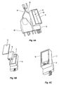
- monopolar plug 50 includes a plug housing 52 having an inner surface 52a. Inner surface 52a defines a compartment 54 configured for housing battery 56 which, as noted above, may be the energy source utilized for powering powered deployment assemblies 80, 180 ( Figs. 3-4 and 5 , respectively), or any other suitable powered deployment assembly.
- compartment 54 includes a rectangular cross-section, as shown in Figs. 6A-6C .. However, it is contemplated that compartment 54 may include any cross-section suitable for housing battery 56, e.g., depending upon the configuration, type, dimensions, etc. of battery 56.
- Battery 56 forms part of deployment circuit "DC" ( Figs. 3 - 5 ).
- powered deployment assembly 80 for example, upon activation of monopolar activation switch 4b ( Figs. 3 and 4 ), battery 56 supplied suitable power to create the magnetic field necessary to deploy monopolar assembly 200 ( Figs. 2A-2D ).
- powered deployment assembly 180 As another example, upon activation of switch 3 ( Fig. 5 ), battery 56 provides suitable power to motor 182 is actuate first gear 184, second gear 186, threaded rod 188, and threaded nut 190 to deploy and/or retract monopolar assembly 200 ( Figs. 2A-2D ).
- battery 56 is a 9V battery. However, it is contemplated that battery 56 may be any energy source suitable for powering powered deployment assembly 80 ( Figs. 3 and 4 ), powered deployment assembly 180 ( Fig. 5 ), or other suitable powered deployment assembly.
- plug housing 52 further includes a housing door 58 for selectively enclosing battery 56 inside compartment 54.
- Housing door 58 may be selectively secured to housing 52 using any suitable structure such as, for example, mechanical fasteners, friction or snap fit arrangement, tongue and groove configuration, etc. Regardless of the structure securing housing door 58 to housing 52, it is contemplated that the user will be able to access compartment 54 to swap out battery 56 as needed.
- Providing a battery 56 within plug housing 52 obviates the need to provide a generator having a suitable energy source for powering the powered deployment assembly 80 ( Figs. 3 and 4 ), 180 ( Fig. 5 ), e.g., in additional to the bipolar and monopolar energy sources.
- forceps 10 may be used in conjunction with any suitable generator that would likewise be capable of powering a similar device having a manual deployment assembly.
- the positioning of battery 56 within plug housing 52, as opposed to on, in, or adjacent to housing 20, does not add additional weight to forceps 10 (plug housing 52 will typically sit on the table, stand, or other support surface supporting generator "G") and, thus, does not further surgeon fatigue.
- the above-detailed configuration enables battery 56 to be readily removed and replaced as necessary.
- plug assembly having plug housing 52 with battery 56 therein be configured for powering any other suitable powered mechanism of forceps 10 or any other suitable surgical device.
- powered deployment assemblies 80, 180 are not limited to being powered by battery 56, but may be powered by any other suitable power source.
- forceps 10 in both the bipolar mode, e.g., for grasping, treating and/or cutting tissue, and the monopolar mode, e.g., for electrical/electromechanical tissue treatment, is described with reference to Figs. 1-4 and 6A-6C .
- the use and operation of forceps 10 is detailed below in conjunction with powered deployment assembly 80.
- the use and operation of forceps 10 in conjunction with powered deployment assembly 180 ( Fig. 5 ) is similar to that of powered deployment assembly 80, except where specifically contradicted above with respect to the description of powered deployment assembly 180 ( Fig. 5 ).
- actuator 84 is disposed in its proximal position adjacent proximal portion 86a of guide 86, corresponding to the un-actuated position of powered deployment assembly 80 and the storage position of monopolar assembly 200, wherein insulative sleeve 210 is positioned proximally of jaw members 110, 120, and electrically-conductive tip 224 of energizable member 220 is disposed within insulative groove 126 of jaw flange 124 of jaw member 120.
- movable handle 32 is disposed in its initial position such that jaw members 110, 120 are disposed in the spaced-apart position.
- trigger 62 of trigger assembly 60 remains un-actuated such that the knife remains disposed in its retracted position.
- end effector assembly 100 may be maneuvered into position such that tissue to be grasped, treated, e.g., sealed, and/or cut, is disposed between jaw members 110, 120.
- movable handle 32 is depressed, or pulled proximally relative to fixed handle 34 such that jaw member 110 is pivoted relative to jaw member 120 from the spaced-apart position to the approximated position to grasp tissue therebetween, as shown in Fig. 2B .
- energy may be supplied, e.g., via activation of bipolar activation switch 4a, to plate 112 of jaw member 110 and/or plate 122 of jaw member 120 and conducted through tissue to treat tissue, e.g., to effect a tissue seal or otherwise treat tissue in the bipolar mode of operation.
- the knife (not shown) may be deployed from within shaft 12 to between jaw members 110, 120, e.g., via actuation of trigger 62 of trigger assembly 60, to cut tissue grasped between jaw members 110, 120.
- trigger 62 may be released to return the knife (not shown) to the retracted position. Thereafter, movable handle 32 may be released or returned to its initial position such that jaw members 110, 120 are moved back to the spaced-apart position ( Fig. 2A ) to release the treated and/or divided tissue.
- jaw members 110, 120 are first moved to the approximated position, e.g., by depressing movable handle 32 relative to fixed handle 34.
- monopolar assembly 200 may be deployed and activated by transitioning the powered deployment assembly 80 from the un-actuated condition to the actuated condition ( Fig. 4 ).
- monopolar activation switch 4b is activated to establish the magnetic field and move actuator 84 to translate distally along guide 86 from the proximal position shown in Fig. 3 to the distal position shown in Fig. 4 .
- deployment circuit "DC" when monopolar activation switch 4b is activated, deployment circuit "DC" is in a closed condition, thereby allowing current flow from the energy source, e.g., battery 56 or other suitable energy source.
- the magnetic field is produced around at least a portion of electromagnet 82.
- the magnetic field acts on actuator 84 such that actuator 84 translates distally towards electromagnet 82 ( Fig. 4 ) against the bias of biasing member 88 to deploy monopolar assembly 200.
- actuator 84 triggers distal sensor 40b such that distal sensor 40b communicates with electrosurgical generator "G" to initiate the supply of monopolar voltage-current to energizable member 220.
- electrosurgical generator "G” continues to supply monopolar voltage-current to energizable member 220 for a duration that monopolar activation switch 4b remains activated.
- Other additional or alternative energy delivery algorithms are also contemplated.
- deployment circuit "DC" Upon deactivation, e.g., release, of monopolar activation switch 4b, deployment circuit "DC" changes to an open condition and current flow is stopped. In this condition, there is no longer a magnetic field produced around at least a portion of electromagnet 82 to attract actuator 84. As such, the bias of biasing member 88 urges actuator 84 proximally towards proximal portion 86a of guide 86 to return monopolar assembly 200 to the storage position.
- sensor 40a communicates with electrosurgical generator "G” to terminate the supply of monopolar voltage-current to energizable member 220. Alternatively, the supply of energy may be terminated as soon as monopolar assembly 200 begins to be retracted from the deployed position, e.g., as soon as actuator 84 departs the distal position.
- the various embodiments disclosed herein may also be configured to work with robotic surgical systems and what is commonly referred to as "Telesurgery.”
- Such systems employ various robotic elements to assist the surgeon and allow remote operation (or partial remote operation) of surgical instrumentation.
- Various robotic arms, gears, cams, pulleys, electric and mechanical motors, etc. may be employed for this purpose and may be designed with a robotic surgical system to assist the surgeon during the course of an operation or treatment.
- Such robotic systems may include remotely steerable systems, automatically flexible surgical systems, remotely flexible surgical systems, remotely articulating surgical systems, wireless surgical systems, modular or selectively configurable remotely operated surgical systems, etc.
- the robotic surgical systems may be employed with one or more consoles that are next to the operating theater or located in a remote location.
- one team of surgeons or nurses may prep the patient for surgery and configure the robotic surgical system with one or more of the instruments disclosed herein while another surgeon (or group of surgeons) remotely control the instruments via the robotic surgical system.
- a highly skilled surgeon may perform multiple operations in multiple locations without leaving his/her remote console which can be both economically advantageous and a benefit to the patient or a series of patients.
- the robotic arms of the surgical system are typically coupled to a pair of master handles by a controller.
- the handles can be moved by the surgeon to produce a corresponding movement of the working ends of any type of surgical instrument (e.g., end effectors, graspers, knifes, scissors, etc.) which may complement the use of one or more of the embodiments described herein.
- the movement of the master handles may be scaled so that the working ends have a corresponding movement that is different, smaller or larger, than the movement performed by the operating hands of the surgeon.
- the scale factor or gearing ratio may be adjustable so that the operator can control the resolution of the working ends of the surgical instrument(s).
- the master handles may include various sensors to provide feedback to the surgeon relating to various tissue parameters or conditions, e.g., tissue resistance due to manipulation, cutting or otherwise treating, pressure by the instrument onto the tissue, tissue temperature, tissue impedance, etc. As can be appreciated, such sensors provide the surgeon with enhanced tactile feedback simulating actual operating conditions.
- the master handles may also include a variety of different actuators for delicate tissue manipulation or treatment further enhancing the surgeon's ability to mimic actual operating conditions.
Landscapes
- Health & Medical Sciences (AREA)
- Surgery (AREA)
- Engineering & Computer Science (AREA)
- Life Sciences & Earth Sciences (AREA)
- Biomedical Technology (AREA)
- Otolaryngology (AREA)
- Nuclear Medicine, Radiotherapy & Molecular Imaging (AREA)
- Plasma & Fusion (AREA)
- Physics & Mathematics (AREA)
- Heart & Thoracic Surgery (AREA)
- Medical Informatics (AREA)
- Molecular Biology (AREA)
- Animal Behavior & Ethology (AREA)
- General Health & Medical Sciences (AREA)
- Public Health (AREA)
- Veterinary Medicine (AREA)
- Surgical Instruments (AREA)
Applications Claiming Priority (1)
| Application Number | Priority Date | Filing Date | Title |
|---|---|---|---|
| US14/542,766 US9867656B2 (en) | 2014-11-17 | 2014-11-17 | Multi-function surgical instruments |
Publications (3)
| Publication Number | Publication Date |
|---|---|
| EP3040041A2 true EP3040041A2 (fr) | 2016-07-06 |
| EP3040041A3 EP3040041A3 (fr) | 2016-11-30 |
| EP3040041B1 EP3040041B1 (fr) | 2018-03-14 |
Family
ID=54360167
Family Applications (1)
| Application Number | Title | Priority Date | Filing Date |
|---|---|---|---|
| EP15191274.8A Active EP3040041B1 (fr) | 2014-11-17 | 2015-10-23 | Instrument électrochirurgical avec un ensemble de déploiement actionné pour déplacer un membre alimentable en énergie |
Country Status (2)
| Country | Link |
|---|---|
| US (2) | US9867656B2 (fr) |
| EP (1) | EP3040041B1 (fr) |
Cited By (1)
| Publication number | Priority date | Publication date | Assignee | Title |
|---|---|---|---|---|
| US11534228B2 (en) | 2014-08-12 | 2022-12-27 | Invuity, Inc. | Illuminated electrosurgical system and method of use |
Families Citing this family (8)
| Publication number | Priority date | Publication date | Assignee | Title |
|---|---|---|---|---|
| CN111405878A (zh) * | 2017-11-29 | 2020-07-10 | 柯惠Lp公司 | 机器人手术系统、器械驱动组件以及驱动组件 |
| US11419665B2 (en) | 2018-10-26 | 2022-08-23 | Covidien Lp | Electrosurgical forceps |
| US11510725B2 (en) | 2019-01-30 | 2022-11-29 | Covidien Lp | Electrosurgical forceps |
| US11304743B2 (en) | 2019-01-30 | 2022-04-19 | Covidien Lp | Electrosurgical forceps |
| US11497545B2 (en) | 2019-02-14 | 2022-11-15 | Covidien Lp | Electrosurgical forceps |
| US12426941B2 (en) * | 2020-03-20 | 2025-09-30 | Covidien Lp | Surgical instruments and systems configured to detect, analyze, and/or distinguish smoke and steam during a surgical procedure |
| WO2022246008A1 (fr) * | 2021-05-19 | 2022-11-24 | Palladium Medical LLC | Dispositif électrochirurgical |
| US20240090937A1 (en) * | 2022-09-21 | 2024-03-21 | Mohile Innovative Solutions LLC | Electrosurgical device with a deployable electrode tip and integrated modulated smoke evacuation and suction control |
Family Cites Families (63)
| Publication number | Priority date | Publication date | Assignee | Title |
|---|---|---|---|---|
| US5919202A (en) | 1989-12-05 | 1999-07-06 | Yoon; Inbae | Surgical instrument with jaws and movable internal needle and method for use thereof |
| US5893863A (en) | 1989-12-05 | 1999-04-13 | Yoon; Inbae | Surgical instrument with jaws and movable internal hook member for use thereof |
| US5195958A (en) | 1990-05-25 | 1993-03-23 | Phillips Edward H | Tool for laparoscopic surgery |
| US5318589A (en) | 1992-04-15 | 1994-06-07 | Microsurge, Inc. | Surgical instrument for endoscopic surgery |
| JPH05293115A (ja) | 1992-04-20 | 1993-11-09 | Olympus Optical Co Ltd | 高周波処置具 |
| US5312391A (en) | 1992-07-29 | 1994-05-17 | Wilk Peter J | Laparoscopic instrument assembly |
| US5445638B1 (en) | 1993-03-08 | 1998-05-05 | Everest Medical Corp | Bipolar coagulation and cutting forceps |
| US5458598A (en) | 1993-12-02 | 1995-10-17 | Cabot Technology Corporation | Cutting and coagulating forceps |
| US5556397A (en) | 1994-10-26 | 1996-09-17 | Laser Centers Of America | Coaxial electrosurgical instrument |
| US5792164A (en) | 1994-12-19 | 1998-08-11 | Lakatos; Nick | Surgical instrument |
| US5931810A (en) | 1996-12-05 | 1999-08-03 | Comedicus Incorporated | Method for accessing the pericardial space |
| US5735873A (en) | 1996-12-19 | 1998-04-07 | Maclean; David S. | Surgical tool handle |
| US6113596A (en) | 1996-12-30 | 2000-09-05 | Enable Medical Corporation | Combination monopolar-bipolar electrosurgical instrument system, instrument and cable |
| US7198635B2 (en) * | 2000-10-17 | 2007-04-03 | Asthmatx, Inc. | Modification of airways by application of energy |
| US6679882B1 (en) | 1998-06-22 | 2004-01-20 | Lina Medical Aps | Electrosurgical device for coagulating and for making incisions, a method of severing blood vessels and a method of coagulating and for making incisions in or severing tissue |
| DE19836481C1 (de) | 1998-08-12 | 2000-03-30 | Storz Karl Gmbh & Co Kg | Handgriff für ein medizinisches Instrument |
| JP4225624B2 (ja) | 1998-08-27 | 2009-02-18 | オリンパス株式会社 | 高周波処置装置 |
| DE19850068C1 (de) | 1998-10-30 | 2000-06-08 | Storz Karl Gmbh & Co Kg | Medizinisches Instrument zum Präparieren von Gewebe |
| US6190386B1 (en) | 1999-03-09 | 2001-02-20 | Everest Medical Corporation | Electrosurgical forceps with needle electrodes |
| WO2000077876A1 (fr) | 1999-06-16 | 2000-12-21 | Snap-On Technologies, Inc | Outil mecanique et bloc batterie distant convertible associe |
| US6692445B2 (en) | 1999-07-27 | 2004-02-17 | Scimed Life Systems, Inc. | Biopsy sampler |
| US8517923B2 (en) | 2000-04-03 | 2013-08-27 | Intuitive Surgical Operations, Inc. | Apparatus and methods for facilitating treatment of tissue via improved delivery of energy based and non-energy based modalities |
| US6554829B2 (en) | 2001-01-24 | 2003-04-29 | Ethicon, Inc. | Electrosurgical instrument with minimally invasive jaws |
| US6464702B2 (en) | 2001-01-24 | 2002-10-15 | Ethicon, Inc. | Electrosurgical instrument with closing tube for conducting RF energy and moving jaws |
| US6551313B1 (en) | 2001-05-02 | 2003-04-22 | John M. Levin | Electrosurgical instrument with separate cutting and coagulating members |
| US6808525B2 (en) | 2001-08-27 | 2004-10-26 | Gyrus Medical, Inc. | Bipolar electrosurgical hook probe for cutting and coagulating tissue |
| US6942662B2 (en) | 2001-12-27 | 2005-09-13 | Gyrus Group Plc | Surgical Instrument |
| US6974455B2 (en) * | 2002-04-10 | 2005-12-13 | Boston Scientific Scimed, Inc. | Auto advancing radio frequency array |
| US7033356B2 (en) | 2002-07-02 | 2006-04-25 | Gyrus Medical, Inc. | Bipolar electrosurgical instrument for cutting desiccating and sealing tissue |
| US6852110B2 (en) | 2002-08-01 | 2005-02-08 | Solarant Medical, Inc. | Needle deployment for temperature sensing from an electrode |
| JP4035100B2 (ja) | 2003-06-09 | 2008-01-16 | 徹 谷 | 医療用処置具及びこれを備えた医療用処置装置 |
| US7510562B2 (en) | 2003-07-08 | 2009-03-31 | Terumo Corporation | Vein dissector, cauterizing and ligating apparatus for endoscopic harvesting of blood vessels |
| JP2005039147A (ja) | 2003-07-18 | 2005-02-10 | Smc Corp | 低速駆動可能なリニアアクチュエータ |
| US7367976B2 (en) | 2003-11-17 | 2008-05-06 | Sherwood Services Ag | Bipolar forceps having monopolar extension |
| US7232440B2 (en) | 2003-11-17 | 2007-06-19 | Sherwood Services Ag | Bipolar forceps having monopolar extension |
| JP4436698B2 (ja) | 2004-02-25 | 2010-03-24 | オリンパス株式会社 | 高周波処置具 |
| US7402162B2 (en) | 2004-03-24 | 2008-07-22 | Hoya Corporation | High frequency treatment instrument for endoscope |
| US7128254B2 (en) | 2004-09-07 | 2006-10-31 | Ethicon Endo-Surgery, Inc. | Surgical stapling instrument incorporating a multistroke firing mechanism having a rotary slip-clutch transmission |
| NO322695B1 (no) | 2004-12-29 | 2006-11-27 | Surgitech Norway As | Instrument, saerlig til bruk ved laparoskopisk kirurgisk inngrep |
| CA2561034C (fr) | 2005-09-30 | 2014-12-09 | Sherwood Services Ag | Catheter endoscopique flexible avec un effecteur terminal pouvant coaguler et couper les tissus |
| US7815636B2 (en) | 2005-11-29 | 2010-10-19 | Ethicon Endo-Surgery, Inc. | Auto-safety shut-off for energy based devices |
| GB0526151D0 (en) * | 2005-12-22 | 2006-02-01 | Eschmann Holdings Ltd | Improvements in or relating to surgical instruments |
| WO2007118608A1 (fr) | 2006-04-11 | 2007-10-25 | Erbe Elektromedizin Gmbh | Instrument chirurgical multifonctions endoscopique |
| US7758577B2 (en) | 2006-12-05 | 2010-07-20 | Ethicon Endo-Surgery, Inc. | Monopolar resection device and method of use |
| US20080215050A1 (en) | 2007-03-02 | 2008-09-04 | Ethicon Endo-Surgery, Inc. | Tissue engaging hemostasis device |
| US7753245B2 (en) | 2007-06-22 | 2010-07-13 | Ethicon Endo-Surgery, Inc. | Surgical stapling instruments |
| US7658311B2 (en) | 2007-06-22 | 2010-02-09 | Ethicon Endo-Surgery, Inc. | Surgical stapling instrument with a geared return mechanism |
| US7988026B2 (en) * | 2007-09-06 | 2011-08-02 | Cardica, Inc. | Endocutter with staple feed |
| EP2211744A1 (fr) | 2007-11-13 | 2010-08-04 | Boston Scientific Scimed, Inc. | Appareil, système et procédé de coagulation et ablation de tissus |
| JP2009247696A (ja) | 2008-04-08 | 2009-10-29 | Olympus Medical Systems Corp | 高周波処置具 |
| DE102008030285A1 (de) | 2008-06-30 | 2009-12-31 | Celon Ag Medical Instruments | Elektrochirurgisches Instrument |
| US20100185197A1 (en) | 2009-01-21 | 2010-07-22 | Satomi Sakao | Medical treatment apparatus, treatment instrument and treatment method for living tissue using energy |
| US20100185196A1 (en) | 2009-01-21 | 2010-07-22 | Satomi Sakao | Medical treatment apparatus, treatment instrument and treatment method for living tissue using energy |
| US8197490B2 (en) * | 2009-02-23 | 2012-06-12 | Ellipse Technologies, Inc. | Non-invasive adjustable distraction system |
| WO2010101897A1 (fr) | 2009-03-02 | 2010-09-10 | Bovie Medical Corporation | Appareil chirurgical pour fermeture de tissu et découpe |
| US8496655B2 (en) * | 2009-04-06 | 2013-07-30 | Michael J. O'Donnell | System and method for resecting a valve |
| US9198683B2 (en) | 2009-09-30 | 2015-12-01 | Aegis Medical Innovations, Inc. | Tissue capture and occlusion systems and methods |
| US8939974B2 (en) | 2009-10-09 | 2015-01-27 | Ethicon Endo-Surgery, Inc. | Surgical instrument comprising first and second drive systems actuatable by a common trigger mechanism |
| US8535311B2 (en) | 2010-04-22 | 2013-09-17 | Ethicon Endo-Surgery, Inc. | Electrosurgical instrument comprising closing and firing systems |
| EP2820691B1 (fr) * | 2012-08-29 | 2016-04-06 | Gyrus Acmi Inc. | Bloc-batterie attaché à un câble |
| US9197490B2 (en) * | 2012-10-04 | 2015-11-24 | Dell Products L.P. | System and method for providing remote management of a switching device |
| EP2967735B1 (fr) | 2013-03-15 | 2018-08-29 | Gyrus ACMI, Inc. (d.b.a.Olympus Surgical Technologies America) | Dispositif électrochirurgical combiné |
| US9775667B2 (en) * | 2013-06-18 | 2017-10-03 | Ethicon Llc | Surgical instrument with articulation indicator |
-
2014
- 2014-11-17 US US14/542,766 patent/US9867656B2/en active Active
-
2015
- 2015-10-23 EP EP15191274.8A patent/EP3040041B1/fr active Active
-
2017
- 2017-12-14 US US15/842,546 patent/US11045250B2/en active Active
Non-Patent Citations (1)
| Title |
|---|
| None |
Cited By (3)
| Publication number | Priority date | Publication date | Assignee | Title |
|---|---|---|---|---|
| US11534228B2 (en) | 2014-08-12 | 2022-12-27 | Invuity, Inc. | Illuminated electrosurgical system and method of use |
| EP3179944B1 (fr) * | 2014-08-12 | 2025-08-06 | Invuity, Inc. | Système électro-chirurgical éclairé |
| EP4613231A3 (fr) * | 2014-08-12 | 2025-10-15 | Invuity, Inc. | Système électrochirurgical éclairé et procédé d'utilisation |
Also Published As
| Publication number | Publication date |
|---|---|
| EP3040041B1 (fr) | 2018-03-14 |
| US20160135868A1 (en) | 2016-05-19 |
| US11045250B2 (en) | 2021-06-29 |
| EP3040041A3 (fr) | 2016-11-30 |
| US9867656B2 (en) | 2018-01-16 |
| US20180103997A1 (en) | 2018-04-19 |
Similar Documents
| Publication | Publication Date | Title |
|---|---|---|
| US11045250B2 (en) | Multi-function surgical instruments | |
| US20220211425A1 (en) | Multi-function surgical instrument | |
| CN206482658U (zh) | 外科手术器械和外科手术钳 | |
| EP2762101A2 (fr) | Instrument électro-chirurgical | |
| US12127782B2 (en) | Energy-activation mechanisms for surgical instruments | |
| US10631920B2 (en) | Deployment mechanism for surgical instruments | |
| EP3020352B1 (fr) | Mécanisme de déploiement pour instruments chirurgicaux | |
| EP2997919B1 (fr) | Instruments chirurgicaux multifonctions | |
| US20150327913A1 (en) | Surgical instrument with extendible monopolar element | |
| US10206737B2 (en) | Mechanical cutting system for surgical forceps | |
| US20170209205A1 (en) | Knife trigger for vessel sealer | |
| US20150351828A1 (en) | Surgical instrument including re-usable portion | |
| EP3020353B1 (fr) | Mécanismes de déploiement pour instruments chirurgicaux multifonction | |
| US20200405380A1 (en) | Multi-function surgical instruments |
Legal Events
| Date | Code | Title | Description |
|---|---|---|---|
| PUAI | Public reference made under article 153(3) epc to a published international application that has entered the european phase |
Free format text: ORIGINAL CODE: 0009012 |
|
| 17P | Request for examination filed |
Effective date: 20151023 |
|
| AK | Designated contracting states |
Kind code of ref document: A2 Designated state(s): AL AT BE BG CH CY CZ DE DK EE ES FI FR GB GR HR HU IE IS IT LI LT LU LV MC MK MT NL NO PL PT RO RS SE SI SK SM TR |
|
| AX | Request for extension of the european patent |
Extension state: BA ME |
|
| REG | Reference to a national code |
Ref country code: DE Ref legal event code: R079 Ref document number: 602015008709 Country of ref document: DE Free format text: PREVIOUS MAIN CLASS: A61B0018140000 Ipc: A61B0017000000 |
|
| PUAL | Search report despatched |
Free format text: ORIGINAL CODE: 0009013 |
|
| AK | Designated contracting states |
Kind code of ref document: A3 Designated state(s): AL AT BE BG CH CY CZ DE DK EE ES FI FR GB GR HR HU IE IS IT LI LT LU LV MC MK MT NL NO PL PT RO RS SE SI SK SM TR |
|
| AX | Request for extension of the european patent |
Extension state: BA ME |
|
| RIC1 | Information provided on ipc code assigned before grant |
Ipc: A61B 17/29 20060101ALI20161024BHEP Ipc: A61B 18/00 20060101ALI20161024BHEP Ipc: A61B 17/00 20060101AFI20161024BHEP Ipc: A61B 18/12 20060101ALI20161024BHEP Ipc: A61B 18/14 20060101ALI20161024BHEP |
|
| GRAP | Despatch of communication of intention to grant a patent |
Free format text: ORIGINAL CODE: EPIDOSNIGR1 |
|
| INTG | Intention to grant announced |
Effective date: 20170928 |
|
| RIN1 | Information on inventor provided before grant (corrected) |
Inventor name: JOSEPH, DANIEL Inventor name: SONI, PURVISH Inventor name: BUTCHER, BRIAN Inventor name: JADHAV, AMARSINH D. |
|
| GRAS | Grant fee paid |
Free format text: ORIGINAL CODE: EPIDOSNIGR3 |
|
| GRAA | (expected) grant |
Free format text: ORIGINAL CODE: 0009210 |
|
| AK | Designated contracting states |
Kind code of ref document: B1 Designated state(s): AL AT BE BG CH CY CZ DE DK EE ES FI FR GB GR HR HU IE IS IT LI LT LU LV MC MK MT NL NO PL PT RO RS SE SI SK SM TR |
|
| REG | Reference to a national code |
Ref country code: GB Ref legal event code: FG4D |
|
| REG | Reference to a national code |
Ref country code: CH Ref legal event code: EP Ref country code: AT Ref legal event code: REF Ref document number: 978074 Country of ref document: AT Kind code of ref document: T Effective date: 20180315 |
|
| REG | Reference to a national code |
Ref country code: IE Ref legal event code: FG4D |
|
| REG | Reference to a national code |
Ref country code: DE Ref legal event code: R096 Ref document number: 602015008709 Country of ref document: DE |
|
| REG | Reference to a national code |
Ref country code: NL Ref legal event code: MP Effective date: 20180314 |
|
| REG | Reference to a national code |
Ref country code: LT Ref legal event code: MG4D |
|
| PG25 | Lapsed in a contracting state [announced via postgrant information from national office to epo] |
Ref country code: FI Free format text: LAPSE BECAUSE OF FAILURE TO SUBMIT A TRANSLATION OF THE DESCRIPTION OR TO PAY THE FEE WITHIN THE PRESCRIBED TIME-LIMIT Effective date: 20180314 Ref country code: HR Free format text: LAPSE BECAUSE OF FAILURE TO SUBMIT A TRANSLATION OF THE DESCRIPTION OR TO PAY THE FEE WITHIN THE PRESCRIBED TIME-LIMIT Effective date: 20180314 Ref country code: LT Free format text: LAPSE BECAUSE OF FAILURE TO SUBMIT A TRANSLATION OF THE DESCRIPTION OR TO PAY THE FEE WITHIN THE PRESCRIBED TIME-LIMIT Effective date: 20180314 Ref country code: CY Free format text: LAPSE BECAUSE OF FAILURE TO SUBMIT A TRANSLATION OF THE DESCRIPTION OR TO PAY THE FEE WITHIN THE PRESCRIBED TIME-LIMIT Effective date: 20180314 Ref country code: NO Free format text: LAPSE BECAUSE OF FAILURE TO SUBMIT A TRANSLATION OF THE DESCRIPTION OR TO PAY THE FEE WITHIN THE PRESCRIBED TIME-LIMIT Effective date: 20180614 |
|
| REG | Reference to a national code |
Ref country code: AT Ref legal event code: MK05 Ref document number: 978074 Country of ref document: AT Kind code of ref document: T Effective date: 20180314 |
|
| PG25 | Lapsed in a contracting state [announced via postgrant information from national office to epo] |
Ref country code: BG Free format text: LAPSE BECAUSE OF FAILURE TO SUBMIT A TRANSLATION OF THE DESCRIPTION OR TO PAY THE FEE WITHIN THE PRESCRIBED TIME-LIMIT Effective date: 20180614 Ref country code: SE Free format text: LAPSE BECAUSE OF FAILURE TO SUBMIT A TRANSLATION OF THE DESCRIPTION OR TO PAY THE FEE WITHIN THE PRESCRIBED TIME-LIMIT Effective date: 20180314 Ref country code: LV Free format text: LAPSE BECAUSE OF FAILURE TO SUBMIT A TRANSLATION OF THE DESCRIPTION OR TO PAY THE FEE WITHIN THE PRESCRIBED TIME-LIMIT Effective date: 20180314 Ref country code: RS Free format text: LAPSE BECAUSE OF FAILURE TO SUBMIT A TRANSLATION OF THE DESCRIPTION OR TO PAY THE FEE WITHIN THE PRESCRIBED TIME-LIMIT Effective date: 20180314 Ref country code: GR Free format text: LAPSE BECAUSE OF FAILURE TO SUBMIT A TRANSLATION OF THE DESCRIPTION OR TO PAY THE FEE WITHIN THE PRESCRIBED TIME-LIMIT Effective date: 20180615 |
|
| REG | Reference to a national code |
Ref country code: FR Ref legal event code: PLFP Year of fee payment: 4 |
|
| PG25 | Lapsed in a contracting state [announced via postgrant information from national office to epo] |
Ref country code: PL Free format text: LAPSE BECAUSE OF FAILURE TO SUBMIT A TRANSLATION OF THE DESCRIPTION OR TO PAY THE FEE WITHIN THE PRESCRIBED TIME-LIMIT Effective date: 20180314 Ref country code: IT Free format text: LAPSE BECAUSE OF FAILURE TO SUBMIT A TRANSLATION OF THE DESCRIPTION OR TO PAY THE FEE WITHIN THE PRESCRIBED TIME-LIMIT Effective date: 20180314 Ref country code: EE Free format text: LAPSE BECAUSE OF FAILURE TO SUBMIT A TRANSLATION OF THE DESCRIPTION OR TO PAY THE FEE WITHIN THE PRESCRIBED TIME-LIMIT Effective date: 20180314 Ref country code: RO Free format text: LAPSE BECAUSE OF FAILURE TO SUBMIT A TRANSLATION OF THE DESCRIPTION OR TO PAY THE FEE WITHIN THE PRESCRIBED TIME-LIMIT Effective date: 20180314 Ref country code: NL Free format text: LAPSE BECAUSE OF FAILURE TO SUBMIT A TRANSLATION OF THE DESCRIPTION OR TO PAY THE FEE WITHIN THE PRESCRIBED TIME-LIMIT Effective date: 20180314 Ref country code: AL Free format text: LAPSE BECAUSE OF FAILURE TO SUBMIT A TRANSLATION OF THE DESCRIPTION OR TO PAY THE FEE WITHIN THE PRESCRIBED TIME-LIMIT Effective date: 20180314 Ref country code: ES Free format text: LAPSE BECAUSE OF FAILURE TO SUBMIT A TRANSLATION OF THE DESCRIPTION OR TO PAY THE FEE WITHIN THE PRESCRIBED TIME-LIMIT Effective date: 20180314 |
|
| PG25 | Lapsed in a contracting state [announced via postgrant information from national office to epo] |
Ref country code: AT Free format text: LAPSE BECAUSE OF FAILURE TO SUBMIT A TRANSLATION OF THE DESCRIPTION OR TO PAY THE FEE WITHIN THE PRESCRIBED TIME-LIMIT Effective date: 20180314 Ref country code: SK Free format text: LAPSE BECAUSE OF FAILURE TO SUBMIT A TRANSLATION OF THE DESCRIPTION OR TO PAY THE FEE WITHIN THE PRESCRIBED TIME-LIMIT Effective date: 20180314 Ref country code: SM Free format text: LAPSE BECAUSE OF FAILURE TO SUBMIT A TRANSLATION OF THE DESCRIPTION OR TO PAY THE FEE WITHIN THE PRESCRIBED TIME-LIMIT Effective date: 20180314 Ref country code: CZ Free format text: LAPSE BECAUSE OF FAILURE TO SUBMIT A TRANSLATION OF THE DESCRIPTION OR TO PAY THE FEE WITHIN THE PRESCRIBED TIME-LIMIT Effective date: 20180314 |
|
| REG | Reference to a national code |
Ref country code: DE Ref legal event code: R097 Ref document number: 602015008709 Country of ref document: DE |
|
| PG25 | Lapsed in a contracting state [announced via postgrant information from national office to epo] |
Ref country code: PT Free format text: LAPSE BECAUSE OF FAILURE TO SUBMIT A TRANSLATION OF THE DESCRIPTION OR TO PAY THE FEE WITHIN THE PRESCRIBED TIME-LIMIT Effective date: 20180716 |
|
| PLBE | No opposition filed within time limit |
Free format text: ORIGINAL CODE: 0009261 |
|
| STAA | Information on the status of an ep patent application or granted ep patent |
Free format text: STATUS: NO OPPOSITION FILED WITHIN TIME LIMIT |
|
| PG25 | Lapsed in a contracting state [announced via postgrant information from national office to epo] |
Ref country code: DK Free format text: LAPSE BECAUSE OF FAILURE TO SUBMIT A TRANSLATION OF THE DESCRIPTION OR TO PAY THE FEE WITHIN THE PRESCRIBED TIME-LIMIT Effective date: 20180314 |
|
| 26N | No opposition filed |
Effective date: 20181217 |
|
| PG25 | Lapsed in a contracting state [announced via postgrant information from national office to epo] |
Ref country code: SI Free format text: LAPSE BECAUSE OF FAILURE TO SUBMIT A TRANSLATION OF THE DESCRIPTION OR TO PAY THE FEE WITHIN THE PRESCRIBED TIME-LIMIT Effective date: 20180314 |
|
| REG | Reference to a national code |
Ref country code: CH Ref legal event code: PL |
|
| REG | Reference to a national code |
Ref country code: BE Ref legal event code: MM Effective date: 20181031 |
|
| PG25 | Lapsed in a contracting state [announced via postgrant information from national office to epo] |
Ref country code: LU Free format text: LAPSE BECAUSE OF NON-PAYMENT OF DUE FEES Effective date: 20181023 Ref country code: MC Free format text: LAPSE BECAUSE OF FAILURE TO SUBMIT A TRANSLATION OF THE DESCRIPTION OR TO PAY THE FEE WITHIN THE PRESCRIBED TIME-LIMIT Effective date: 20180314 |
|
| REG | Reference to a national code |
Ref country code: IE Ref legal event code: MM4A |
|
| PG25 | Lapsed in a contracting state [announced via postgrant information from national office to epo] |
Ref country code: CH Free format text: LAPSE BECAUSE OF NON-PAYMENT OF DUE FEES Effective date: 20181031 Ref country code: BE Free format text: LAPSE BECAUSE OF NON-PAYMENT OF DUE FEES Effective date: 20181031 Ref country code: LI Free format text: LAPSE BECAUSE OF NON-PAYMENT OF DUE FEES Effective date: 20181031 |
|
| PG25 | Lapsed in a contracting state [announced via postgrant information from national office to epo] |
Ref country code: IE Free format text: LAPSE BECAUSE OF NON-PAYMENT OF DUE FEES Effective date: 20181023 |
|
| PG25 | Lapsed in a contracting state [announced via postgrant information from national office to epo] |
Ref country code: MT Free format text: LAPSE BECAUSE OF NON-PAYMENT OF DUE FEES Effective date: 20181023 |
|
| PG25 | Lapsed in a contracting state [announced via postgrant information from national office to epo] |
Ref country code: TR Free format text: LAPSE BECAUSE OF FAILURE TO SUBMIT A TRANSLATION OF THE DESCRIPTION OR TO PAY THE FEE WITHIN THE PRESCRIBED TIME-LIMIT Effective date: 20180314 |
|
| PG25 | Lapsed in a contracting state [announced via postgrant information from national office to epo] |
Ref country code: HU Free format text: LAPSE BECAUSE OF FAILURE TO SUBMIT A TRANSLATION OF THE DESCRIPTION OR TO PAY THE FEE WITHIN THE PRESCRIBED TIME-LIMIT; INVALID AB INITIO Effective date: 20151023 Ref country code: MK Free format text: LAPSE BECAUSE OF NON-PAYMENT OF DUE FEES Effective date: 20180314 |
|
| PG25 | Lapsed in a contracting state [announced via postgrant information from national office to epo] |
Ref country code: IS Free format text: LAPSE BECAUSE OF FAILURE TO SUBMIT A TRANSLATION OF THE DESCRIPTION OR TO PAY THE FEE WITHIN THE PRESCRIBED TIME-LIMIT Effective date: 20180714 |
|
| PGFP | Annual fee paid to national office [announced via postgrant information from national office to epo] |
Ref country code: GB Payment date: 20250923 Year of fee payment: 11 |
|
| PGFP | Annual fee paid to national office [announced via postgrant information from national office to epo] |
Ref country code: FR Payment date: 20250923 Year of fee payment: 11 |
|
| PGFP | Annual fee paid to national office [announced via postgrant information from national office to epo] |
Ref country code: DE Payment date: 20250923 Year of fee payment: 11 |