EP3040176A1 - Fertigungsanlage - Google Patents
Fertigungsanlage Download PDFInfo
- Publication number
- EP3040176A1 EP3040176A1 EP15197503.4A EP15197503A EP3040176A1 EP 3040176 A1 EP3040176 A1 EP 3040176A1 EP 15197503 A EP15197503 A EP 15197503A EP 3040176 A1 EP3040176 A1 EP 3040176A1
- Authority
- EP
- European Patent Office
- Prior art keywords
- tool
- molded skin
- robot
- carrier
- production plant
- Prior art date
- Legal status (The legal status is an assumption and is not a legal conclusion. Google has not performed a legal analysis and makes no representation as to the accuracy of the status listed.)
- Granted
Links
- 238000004519 manufacturing process Methods 0.000 title claims abstract description 51
- 239000006260 foam Substances 0.000 claims abstract description 31
- 239000007921 spray Substances 0.000 claims abstract description 8
- 239000007788 liquid Substances 0.000 claims abstract description 3
- 230000008859 change Effects 0.000 claims description 5
- 238000002347 injection Methods 0.000 claims description 4
- 239000007924 injection Substances 0.000 claims description 4
- 239000000463 material Substances 0.000 abstract description 3
- 239000008258 liquid foam Substances 0.000 description 3
- 230000008901 benefit Effects 0.000 description 2
- 230000006735 deficit Effects 0.000 description 2
- 239000012948 isocyanate Substances 0.000 description 2
- 150000002513 isocyanates Chemical class 0.000 description 2
- 238000000034 method Methods 0.000 description 2
- 230000008569 process Effects 0.000 description 2
- 238000013459 approach Methods 0.000 description 1
- 230000009286 beneficial effect Effects 0.000 description 1
- 239000000969 carrier Substances 0.000 description 1
- 238000004140 cleaning Methods 0.000 description 1
- 230000001419 dependent effect Effects 0.000 description 1
- 238000010586 diagram Methods 0.000 description 1
- 230000004069 differentiation Effects 0.000 description 1
- 230000000694 effects Effects 0.000 description 1
- 238000005187 foaming Methods 0.000 description 1
- 238000010438 heat treatment Methods 0.000 description 1
- 238000012432 intermediate storage Methods 0.000 description 1
- 238000005457 optimization Methods 0.000 description 1
- 229920005862 polyol Polymers 0.000 description 1
- 150000003077 polyols Chemical class 0.000 description 1
- 229920002635 polyurethane Polymers 0.000 description 1
- 239000004814 polyurethane Substances 0.000 description 1
- 238000002360 preparation method Methods 0.000 description 1
- 230000001681 protective effect Effects 0.000 description 1
- 239000000243 solution Substances 0.000 description 1
- 239000000126 substance Substances 0.000 description 1
Images
Classifications
-
- B—PERFORMING OPERATIONS; TRANSPORTING
- B29—WORKING OF PLASTICS; WORKING OF SUBSTANCES IN A PLASTIC STATE IN GENERAL
- B29C—SHAPING OR JOINING OF PLASTICS; SHAPING OF MATERIAL IN A PLASTIC STATE, NOT OTHERWISE PROVIDED FOR; AFTER-TREATMENT OF THE SHAPED PRODUCTS, e.g. REPAIRING
- B29C44/00—Shaping by internal pressure generated in the material, e.g. swelling or foaming ; Producing porous or cellular expanded plastics articles
- B29C44/34—Auxiliary operations
- B29C44/58—Moulds
-
- B—PERFORMING OPERATIONS; TRANSPORTING
- B29—WORKING OF PLASTICS; WORKING OF SUBSTANCES IN A PLASTIC STATE IN GENERAL
- B29C—SHAPING OR JOINING OF PLASTICS; SHAPING OF MATERIAL IN A PLASTIC STATE, NOT OTHERWISE PROVIDED FOR; AFTER-TREATMENT OF THE SHAPED PRODUCTS, e.g. REPAIRING
- B29C31/00—Handling, e.g. feeding of the material to be shaped, storage of plastics material before moulding; Automation, i.e. automated handling lines in plastics processing plants, e.g. using manipulators or robots
- B29C31/006—Handling moulds, e.g. between a mould store and a moulding machine
-
- B—PERFORMING OPERATIONS; TRANSPORTING
- B29—WORKING OF PLASTICS; WORKING OF SUBSTANCES IN A PLASTIC STATE IN GENERAL
- B29C—SHAPING OR JOINING OF PLASTICS; SHAPING OF MATERIAL IN A PLASTIC STATE, NOT OTHERWISE PROVIDED FOR; AFTER-TREATMENT OF THE SHAPED PRODUCTS, e.g. REPAIRING
- B29C33/00—Moulds or cores; Details thereof or accessories therefor
- B29C33/20—Opening, closing or clamping
-
- B—PERFORMING OPERATIONS; TRANSPORTING
- B29—WORKING OF PLASTICS; WORKING OF SUBSTANCES IN A PLASTIC STATE IN GENERAL
- B29C—SHAPING OR JOINING OF PLASTICS; SHAPING OF MATERIAL IN A PLASTIC STATE, NOT OTHERWISE PROVIDED FOR; AFTER-TREATMENT OF THE SHAPED PRODUCTS, e.g. REPAIRING
- B29C33/00—Moulds or cores; Details thereof or accessories therefor
- B29C33/34—Moulds or cores; Details thereof or accessories therefor movable, e.g. to or from the moulding station
-
- B—PERFORMING OPERATIONS; TRANSPORTING
- B29—WORKING OF PLASTICS; WORKING OF SUBSTANCES IN A PLASTIC STATE IN GENERAL
- B29C—SHAPING OR JOINING OF PLASTICS; SHAPING OF MATERIAL IN A PLASTIC STATE, NOT OTHERWISE PROVIDED FOR; AFTER-TREATMENT OF THE SHAPED PRODUCTS, e.g. REPAIRING
- B29C44/00—Shaping by internal pressure generated in the material, e.g. swelling or foaming ; Producing porous or cellular expanded plastics articles
- B29C44/02—Shaping by internal pressure generated in the material, e.g. swelling or foaming ; Producing porous or cellular expanded plastics articles for articles of definite length, i.e. discrete articles
- B29C44/12—Incorporating or moulding on preformed parts, e.g. inserts or reinforcements
- B29C44/1228—Joining preformed parts by the expanding material
-
- B—PERFORMING OPERATIONS; TRANSPORTING
- B29—WORKING OF PLASTICS; WORKING OF SUBSTANCES IN A PLASTIC STATE IN GENERAL
- B29C—SHAPING OR JOINING OF PLASTICS; SHAPING OF MATERIAL IN A PLASTIC STATE, NOT OTHERWISE PROVIDED FOR; AFTER-TREATMENT OF THE SHAPED PRODUCTS, e.g. REPAIRING
- B29C44/00—Shaping by internal pressure generated in the material, e.g. swelling or foaming ; Producing porous or cellular expanded plastics articles
- B29C44/34—Auxiliary operations
- B29C44/36—Feeding the material to be shaped
- B29C44/367—Feeding the material to be shaped using spray nozzles
-
- B—PERFORMING OPERATIONS; TRANSPORTING
- B29—WORKING OF PLASTICS; WORKING OF SUBSTANCES IN A PLASTIC STATE IN GENERAL
- B29C—SHAPING OR JOINING OF PLASTICS; SHAPING OF MATERIAL IN A PLASTIC STATE, NOT OTHERWISE PROVIDED FOR; AFTER-TREATMENT OF THE SHAPED PRODUCTS, e.g. REPAIRING
- B29C44/00—Shaping by internal pressure generated in the material, e.g. swelling or foaming ; Producing porous or cellular expanded plastics articles
- B29C44/34—Auxiliary operations
- B29C44/60—Measuring, controlling or regulating
-
- B—PERFORMING OPERATIONS; TRANSPORTING
- B29—WORKING OF PLASTICS; WORKING OF SUBSTANCES IN A PLASTIC STATE IN GENERAL
- B29K—INDEXING SCHEME ASSOCIATED WITH SUBCLASSES B29B, B29C OR B29D, RELATING TO MOULDING MATERIALS OR TO MATERIALS FOR MOULDS, REINFORCEMENTS, FILLERS OR PREFORMED PARTS, e.g. INSERTS
- B29K2075/00—Use of PU, i.e. polyureas or polyurethanes or derivatives thereof, as moulding material
-
- B—PERFORMING OPERATIONS; TRANSPORTING
- B29—WORKING OF PLASTICS; WORKING OF SUBSTANCES IN A PLASTIC STATE IN GENERAL
- B29L—INDEXING SCHEME ASSOCIATED WITH SUBCLASS B29C, RELATING TO PARTICULAR ARTICLES
- B29L2031/00—Other particular articles
- B29L2031/30—Vehicles, e.g. ships or aircraft, or body parts thereof
- B29L2031/3005—Body finishings
- B29L2031/3008—Instrument panels
Definitions
- the invention relates to a manufacturing plant for producing a component which consists of a molded skin, a carrier and a foam layer arranged between the molded skin and the carrier.
- Components which consist of a molded skin, a carrier and a foam layer arranged between the molded skin and the carrier can be used, for example, as a dashboard of a motor vehicle. So far, extremely complex manufacturing systems are used for the production of such a component, which consist of a variety of costly machine tools. Nevertheless, it has not yet been possible to fill out waiting times in terms of manufacturing technology or to avoid such waiting times. The waiting times are required to allow the originally liquid foam injected into the molded skin to cure, so that the carrier and the molded skin can cohesively bond to one another via the foam layer. When cured, polyol and isocyanate react to form polyurethane.
- the invention has for its object to provide an overall simplified manufacturing system that allows continuous and automated as possible largely without interruption the production of components that consist of a support, a molded skin and an existing between the carrier and the molded skin foam layer.
- the advantages of the invention are in particular in the very compact, limited to a narrow space execution of such a manufacturing plant, which also consists of only a few facilities and no longer requires numerous machine tools.
- the principle of "short distances" is used.
- An essential, inventive aspect is that at least one program-controlled robot is used, which is used to move the entire tool in different directions of movement and also opens and closes the individual tools. It is possible to separate the upper tool and the lower tool by means of the robot in each direction of movement from each other or to connect with each other and / or pivotally connected to each other about an axis of rotation.
- a combination of detachable connection and pivoting about an at least virtual axis of rotation is also within the scope of the invention.
- the lower tool and the upper tool are detachably connected to each other in each of the tools used, this can be achieved that no downtime occurs.
- the lower tools or upper tools can be equipped independently of each other and connected with each other in this way.
- the waiting time required for curing the foam layer is used in a noticeable way by the robot spending the closed tool for the time of curing in a parking position. Since the tool change is no longer performed on a rotary table, but the parking position is used for "intermediate storage", arise in the area of the rotary table also no more waiting time, as was the case so far.
- the workflows are simplified by the manufacturing plant according to the invention as a whole and the individual stations connected in a meaningful way, so that a process optimization is possible.
- the rotary table has only two or three processing positions.
- the rotary table has a very simple structure and nevertheless makes it possible to provide all the processing stations which are required for the production of the component consisting of a carrier, a molded skin and a foam layer arranged between carrier and molded skin.
- This design of the rotary table is a not inconsiderable aspect of the compact design of the manufacturing plant.
- the closed tools which are provided with the molded skin, the carrier and the foam layer can be spent in the tool magazine to remain there in the park position until the foam layer is fully cured and thus the component is completed. The component thus produced can then be removed from the tool.
- Another advantage of the tool magazine with the existing parking positions is that at least one of the parking positions can be used for a tool change. In the ongoing production process, it can happen again and again that individual tools must be replaced. An additional parking position within the tool magazine is helpful for this. In order to ensure that no downtime is required in the production, therefore, an additional parking position in the Tool magazine be kept in order to use this parking position for the aforementioned tool change can.
- a special embodiment of the invention is that the production plant has two robots, of which a first robot for handling the tool consisting of lower tool and upper tool and the second robot for applying the foam layer can be used. Through this division of labor of the robot optimum utilization of the manufacturing facility is achieved according to the invention.
- the second robot is also disposed within the spray booth.
- a hermetic seal of this part of the manufacturing plant can be achieved and the impairment of the operators operating in the environment can be minimized. This measure ultimately serves the safety of work and the protection of the operators and also allows a complete automation of the injection process.
- two different approaches can be selected, which are that the molded skin is inserted manually or by means of a robot in the lower tool and / or the carrier manually or by means of a robot in the upper tool.
- the use of a robot in this context allows a step towards full automation.
- an electric heater of the tool has been found to be particularly advantageous, since it can be implemented with relatively little energy and in a short time and thus allows rapid heating of the tool. The cycle times for the production of the component can thus be significantly reduced.
- a particularly advantageous embodiment of the production plant is to be seen in that the molded skin and the carrier are fixed by means of a vacuum-generating pneumatic device in the respective mold half.
- the manufacturing plant as a whole is electrically operable. Consequently, as far as possible all functions are carried out by means of electrical power, so that in this case a uniform energy source is available and thus the complexity of the entire manufacturing plant can be reduced.
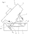
- the FIG. 1 shows first an example of the possibility of executing a tool 5, of which several can be used in a manufacturing plant according to the invention.
- the tool 5 is in this case constructed substantially in two parts and consists of a lower tool 6, which is detachably connected to an upper tool 8 and pivotable about an axis of rotation 7.
- the axis of rotation 7 is not a constructional axis of rotation, but rather a virtual axis of rotation 7.
- a carrier 2 is hereby inserted into a cavity of the upper tool 8, which has its negative shape for precisely fitting the carrier 2.
- the support 2 opposite is located in the lower tool 6, a molded skin 3, which in turn is precisely inserted into a negative mold of the molded skin having cavity 22.
- a foam layer 4 of an originally liquid foam material is applied to the molded skin 3, which produces a cohesive connection between the support 2 and the molded skin 3 after the closing of the tool 5 by its curing.
- the illustrated component is the dashboard for a motor vehicle. Since this component has an undercut 21, the use of a slider 20 is required in the tool 5 shown. The slider 20 can therefore within the Lower tool 6 are moved in the direction of the double arrow A, so that the slider 20 can be reciprocated between one of the molded skin 3 and the finished component fixing and a releasing this position. A peculiarity of in FIG.
- 1 illustrated tool 5 is that the outside of the upper tool 8, a tool flange 23 is arranged, which allows the gripping of the entire upper tool 8 and the entire, closed tool 5 with a robot arm, so that the tool 5 is opened and closed by a robot 9 can be moved back and forth between different positions within the production line.
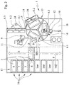
- FIG. 2 shows an embodiment of a complete manufacturing plant 1.
- This production plant 1 At the heart of this production plant 1 are initially two program-controlled robots 9 and 10, which are used in each case for different, automated tasks within the production plant 1.
- the robot 9 has a robot arm 11, while the robot 10 is equipped with a robot arm 12.
- the central processing station of the manufacturing plant 1 represents in the present example, a rotary table 13, which is equipped with three different positions. These are an assembly position 14, a connection position 15 and an injection position 16. As the term "round table” already clarifies, this is rotatable about a central axis of rotation.
- the method for producing a component which consists of a carrier 2, a molded skin 3 and a foam layer 4 arranged between the carrier 2 and the molded skin 3, in the present case runs off, initially by the robot 9, a lower tool 6.1 from a parking position 18 of a tool magazine 17 removed and transferred to the loading position 14 of the rotary table 13.
- the selected lower tool 6.1 can initially be removed from the parking position 18 of the tool magazine 17 in the direction of the arrow F and moved over a tool shuttle in the direction of the arrow E, so that it in the Engagement area of the robot 9 passes.
- the acquisition of the lower tool 6.1 by the robot 9 is in the FIG. 2 illustrated by the arrow C.
- the rotary table 13 is rotated by 120 ° in the clockwise direction, so that the tool 6.1 now comes into the engagement region of a first operator 24, which inserts the molded skin 3 in the lower tool 6.1.
- the next tool 6.1 is already transported by the robot 9 in the loading position 14 of the rotary table 13, so that the process runs continuously.
- the lower mold now having a molded skin 3 is denoted by 6.2 and subsequently brought by a renewed rotation of the rotary table 13 by 120 ° in the spray position 16, where within the hermetically sealed to the outside against the escape of chemical vapors spray booth 19 by the second robot 10th the liquid foam is injected into the molded skin 3.
- the sub-tool now designated for differentiation 6.3 is in the connecting position 15, where it is coupled to a previously loaded by a second operator 24 with a carrier 2 upper tool 8.1.
- the closing of the tool 5 by the upper tool 8.1 is pivoted about the virtual axis of rotation 7 and by means of in the representation of FIG. 2 not shown locking elements is fixed in a closed state.
- locking elements here clamping modules can be used.
- these activities are also performed by the robot 9, which subsequently delivers the closed tool 5 in the direction of the arrow D, so that it can be transferred via the tool shuttle in the direction of the arrow E into a parking position 18 of the tool magazine 17, where the Foam layer 4 hardens and thus produces the cohesive connection between the carrier 2 and the molded skin 3.
- the entire tool 5 can be returned to the rotary table 13 to open it by the robot 9, so that the removal of the finished component by means of the robot 9 or through the Operator 24 is possible. After a brief cleaning of the tool 5, this can be provided immediately thereafter for the next following production process.
- the robot 9 which subsequently delivers the closed tool 5 in the direction of the arrow D, so that it can be transferred via the tool shuttle in the direction of the arrow E into a parking position 18 of the tool magazine 17, where the Foam layer 4 hardens and thus produces the cohesive connection between the carrier 2 and the molded skin 3.
- the entire tool 5 can be returned to the rotary table 13 to open it by the robot 9, so that the removal of the finished component by means
Landscapes
- Engineering & Computer Science (AREA)
- Mechanical Engineering (AREA)
- Robotics (AREA)
- Casting Or Compression Moulding Of Plastics Or The Like (AREA)
Abstract
Description
- Die Erfindung betrifft eine Fertigungsanlage zur Herstellung eines Bauteils, das aus einer Formhaut, einem Träger und einer zwischen der Formhaut und dem Träger angeordneten Schaumstoffschicht besteht.
- Bauteile, die aus einer Formhaut, einem Träger und einer zwischen der Formhaut und dem Träger angeordneten Schaumstoffschicht bestehen, können beispielsweise als Armaturenbrett eines Kraftfahrzeuges zum Einsatz kommen. Bislang werden zur Herstellung eines derartigen Bauteils extrem aufwändige Fertigungsanlagen eingesetzt, die aus einer Vielzahl kostenintensiver Werkzeugmaschinen bestehen. Dennoch ist es bisher nicht gelungen, entstehende Wartezeiten fertigungstechnisch sinnvoll auszufüllen beziehungsweise derartige Wartezeiten zu vermeiden. Die Wartezeiten sind erforderlich, um den ursprünglich flüssigen und in die Formhaut eingespritzten Schaumstoff aushärten zu lassen, so dass sich der Träger und die Formhaut über die Schaumstoffschicht stoffschlüssig miteinander verbinden können. Bei der Aushärtung reagieren Polyol und Isocyanat zu Polyurethan. Selbst der Einsatz von Rundtischen hat hier bislang keinen wesentlichen Fortschritt gebracht, da bisher auch in diesem Fall Stillstandszeiten entstehen, beispielsweise durch den Umstand, dass einzelne Werkzeuge zeitweilig nicht genutzt werden oder bei erforderlichen Werkzeugwechseln. Darüber hinaus ist festzustellen, dass in bekannten Fertigungsanlagen eine Vielzahl einzelner Arbeitskräfte erforderlich sind, um die komplexen Arbeitsschritte zur Herstellung der genannten Bauteile durchführen zu können beziehungsweise diese vorzubereiten. Durch die entstehenden Wartezeiten sind auch diese Arbeitskräfte nicht vollständig ausgelastet. Insgesamt stellt sich die Fertigung derartiger Bauteile demnach bislang recht unbefriedigend, zu langsam und wegen der kostenintensiven Werkzeugmaschinen wenig rentabel dar.
- Der Erfindung liegt die Aufgabe zugrunde, eine insgesamt vereinfachte Fertigungsanlage bereitzustellen, die möglichst ohne Unterbrechungen kontinuierlich und möglichst weitgehend automatisiert die Fertigung von Bauteilen erlaubt, die aus einem Träger, einer Formhaut und einer zwischen Träger und Formhaut vorhandenen Schaumstoffschicht bestehen.
- Die Erfindung löst diese Aufgabenstellung mit den Merkmalen des Anspruches 1.
- Eine erfindungsgemäße Fertigungsanlage zur Herstellung eines Bauteils mittels einer stoffschlüssigen Verbindung zwischen einem Träger, einer Formhaut und einer zwischen Träger und Formhaut angeordneten Schaumstoffschicht, weist folgende Merkmale auf:
- mehrere, im Aufbau gleiche oder gleichartige Werkzeuge,
- jedes der Werkzeuge besteht aus einem Unterwerkzeug und einem lösbar und/oder um eine Drehachse schwenkbar mit dem Unterwerkzeug verbundenen Oberwerkzeug,
- das Oberwerkzeug ist dabei jeweils zur Aufnahme eines Trägers und das Unterwerkzeug zur Einbringung einer Formhaut geeignet, wobei auf die Formhaut eine ursprünglich flüssige, selbstaushärtende Schaumstoffschicht aufgebracht ist und Träger, Formhaut und Schaumstoffschicht durch Schließen des Werkzeugs miteinander verbindbar sind,
- jedes Werkzeug ist zum Verschließen mit einer Verriegelungseinrichtung ausgestattet,
- wenigstens ein durch ein Programm gesteuerter Roboter verfügt über mindestens einen Roboterarm zur Bewegung des gesamten Werkzeugs,
- ein drehbarer Rundtisch, der durch den Roboter in einer Bestückungsposition mit einem mit der Formhaut ausgestatteten Unterwerkzeug bestückbar ist,
- eine Spritzposition des Rundtisches, zum Auftrag der Schaumstoffschicht auf die Formhaut,
- das Unterwerkzeug ist in einer Verbindungsposition des Rundtisches mit einem den Träger enthaltenden Oberwerkzeug verbind- und verschließbar,
- das gesamte, durch den Roboter geschlossene Werkzeug ist wechselnd zwischen dem Rundtisch und einer Parkposition bewegbar.
- Die Vorteile der Erfindung bestehen insbesondere in der sehr kompakten, auf einen engen Raum begrenzbaren Ausführung einer derartigen Fertigungsanlage, die zudem aus nur wenigen Einrichtungen besteht und nicht mehr zahlreiche Werkzeugmaschinen erfordert. Genutzt wird hierbei insbesondere das Prinzip der "kurzen Wege". Ein wesentlicher, erfindungsgemäßer Aspekt besteht darin, dass mindestens ein programmgesteuerter Roboter zum Einsatz kommt, der zur Bewegung des gesamten Werkzeugs in unterschiedlichsten Bewegungsrichtungen genutzt wird und darüber hinaus auch die einzelnen Werkzeuge öffnet beziehungsweise schließt. Dabei ist es möglich, das Oberwerkzeug und das Unterwerkzeug mittels des Roboters in jeder Bewegungsrichtung voneinander zu trennen oder miteinander zu verbinden und/oder um eine Drehachse schwenkbar miteinander zu verbinden. Eine Kombination aus lösbarer Verbindung und Schwenkbarkeit um eine zumindest virtuelle Drehachse liegt ebenfalls im Erfindungsbereich. Da bei jedem der zum Einsatz kommenden Werkzeuge das Unterwerkzeug und das Oberwerkzeug lösbar miteinander verbunden sind, kann dadurch erreicht werden, dass keine Stillstandszeiten entstehen. Die Unterwerkzeuge beziehungsweise Oberwerkzeuge können auf diese Weise nämlich unabhängig voneinander bestückt und beliebig miteinander verbunden werden. Die zur Aushärtung der Schaumstoffschicht erforderliche Wartezeit wird in sinnfälliger Weise dadurch genutzt, dass der Roboter das geschlossene Werkzeug für die Zeit der Aushärtung in eine Parkposition verbringt. Da der Werkzeugwechsel nicht mehr auf einem Rundtisch durchgeführt, sondern die Parkposition zur "Zwischenlagerung" genutzt wird, entstehen im Bereich des Rundtisches ebenfalls keine Wartezeiten mehr, wie dies bisher der Fall war. Somit werden durch die erfindungsgemäße Fertigungsanlage die Arbeitsabläufe insgesamt vereinfacht und die einzelnen Stationen in sinnvoller Weise miteinander verbunden, so dass eine Prozessoptimierung möglich wird.
- Weitere Ausgestaltungen der Erfindung sind Gegenstand der Unteransprüche.
- So entspricht es einer ersten Ausgestaltung der Erfindung, dass der Rundtisch lediglich zwei oder drei Bearbeitungspositionen aufweist. Der Rundtisch ist damit insgesamt sehr einfach aufgebaut und ermöglicht es dennoch, sämtliche Bearbeitungsstationen, die für die Fertigung des aus einem Träger, einer Formhaut und einer zwischen Träger und Formhaut angeordneter Schaumstoffschicht bestehenden Bauteils erforderlich sind, vorzusehen. Diese Gestaltung des Rundtisches ist ein nicht unwesentlicher Aspekt der kompakten Ausführung der Fertigungsanlage.
- Für die Umsetzung der zur Aushärtung der Schaumstoffschicht erforderlichen Wartezeiten ist es vorteilhaft, wenn innerhalb eines Werkzeugmagazins der Fertigungsanlage mehrere Parkpositionen vorhanden sind. Auf diese Weise können die geschlossenen Werkzeuge, die mit der Formhaut, dem Träger und der Schaumstoffschicht versehen sind, in das Werkzeugmagazin verbracht werden, um dort in der Parkposition zu verbleiben, bis die Schaumstoffschicht vollständig ausgehärtet und damit das Bauteil fertig gestellt ist. Das damit erzeugte Bauteil kann anschließend aus dem Werkzeug entnommen werden.
- Ein weiterer Vorzug des Werkzeugmagazins mit den vorhandenen Parkpositionen besteht darin, dass mindestens eine der Parkpositionen für einen Werkzeugwechsel nutzbar ist. Im laufenden Fertigungsprozess kann es immer wieder vorkommen, dass einzelne Werkzeuge ausgetauscht werden müssen. Hierfür ist eine zusätzliche Parkposition innerhalb des Werkzeugmagazins hilfreich. Um zu gewährleisten, dass kein Stillstand in der Fertigung erforderlich wird, muss daher eine zusätzliche Parkposition in dem Werkzeugmagazin vorgehalten werden, um diese Parkposition für den erwähnten Werkzeugwechsel nutzen zu können. Die Mindestgröße des Werkzeugmagazins hängt nämlich unmittelbar von der Zykluszeit und der Taktzeit ab. Dabei ist die Anzahl der Werkzeuge n = Zykluszeit / Taktzeit. Für einen effektiven Werkzeugwechsel sollte daher das Werkzeugmagazin mindestens die erwähnten (n+1) Parkpositionen aufweisen.
- Eine spezielle Ausgestaltung der Erfindung geht dahin, dass die Fertigungsanlage zwei Roboter aufweist, von denen ein erster Roboter zur Handhabung des aus Unterwerkzeug und Oberwerkzeug bestehenden Werkzeugs und der zweite Roboter zur Aufbringung der Schaumstoffschicht einsetzbar ist. Durch diese Arbeitsteilung der Roboter wird eine optimale Ausnutzung der Fertigungsanlage im Sinne der Erfindung erreicht.
- Da der Auftrag der Schaumstoffschicht auf die Formhaut mit aufschäumenden Werkstoffen zu einer Geruchsbeeinträchtigung führen kann, die insbesondere wegen des zuvor bereits erwähnten Isocyanats nicht unproblematisch ist, ist es sinnvoll, diesen Arbeitsgang innerhalb einer Spritzkabine durchzuführen. Dementsprechend geht ein weiterführender Vorschlag der Erfindung dahin, dass der zweite Roboter ebenfalls innerhalb der Spritzkabine angeordnet ist. Somit kann eine hermetische Abriegelung dieses Teils der Fertigungsanlage erreicht und die Beeinträchtigung der in der Umgebung tätigen Bedienpersonen auf ein Mindestmaß reduziert werden. Diese Maßnahme dient damit letztlich der Arbeitssicherheit und dem Schutz der Bedienpersonen und ermöglicht zudem eine vollständige Automatisierung des Spritzprozesses.
- Für die Bestückung des Unterwerkzeugs und des Oberwerkzeuges können zwei verschiedene Vorgehensweisen gewählt werden, die darin bestehen, dass die Formhaut manuell oder mittels eines Roboters in das Unterwerkzeug und/oder der Träger manuell oder mittels eines Roboters in das Oberwerkzeug eingesetzt wird. Die Nutzung eines Roboters ermöglicht in diesem Zusammenhang einen Schritt in Richtung Vollautomatisierung.
- Zur Verbesserung der Verbindung zwischen Träger, Formhaut und Schaumstoff ist es förderlich, wenn die Werkzeuge auf einer Temperatur oberhalb der Raumtemperatur erhitzt werden, bevor der Schaumstoff in die Formhaut eingespritzt wird. Hierbei hat sich eine elektrische Heizung des Werkzeugs als besonders vorteilhaft herausgestellt, da diese mit verhältnismäßig geringem Energieaufwand und in kurzer Zeit umsetzbar ist und folglich eine zügige Erwärmung des Werkzeugs ermöglicht. Die Taktzeiten zur Herstellung des Bauteils können damit entscheidend reduziert werden.
- Eine besonders vorteilhafte Ausführungsvariante der Fertigungsanlage ist darin zu sehen, das die Formhaut und der Träger mittels einer ein Vakuum erzeugenden Pneumatikeinrichtung in der jeweiligen Werkzeughälfte fixiert sind. Durch diese Maßnahme reduziert sich der Aufwand bei der Bestückung der Werkzeughälften auf ein Minimum, weil eine Bedienperson oder ein Roboter den Träger beziehungsweise die Formhaut lediglich an die jeweilige Werkzeughälfte ansetzen muss, während das Vakuum die Formhaut beziehungsweise den Träger selbstständig ansaugt und damit in der im Werkzeug vorhandene Kavität fixiert.
- Abgesehen von der zuvor erwähnten Erzeugung eines Vakuums ist es von besonderem Vorteil, wenn die Fertigungsanlage insgesamt elektrisch betreibbar ist. Folglich werden möglichst sämtliche Funktionen mittels elektrischer Leistung ausgeführt, so dass hierbei ein einheitlicher Energieträger zur Verfügung steht und damit die Komplexität der gesamten Fertigungsanlage reduziert werden kann.
- Die Erfindung wird nachfolgend anhand der beigefügten Zeichnungen näher erläutert. Das gezeigte Ausführungsbeispiel stellt dabei keine Einschränkung auf die dargestellte Variante dar, sondern dient lediglich der Erläuterung eines Prinzips der Erfindung.
Gleiche oder gleichartige Bauteile werden stets mit denselben Bezugsziffern bezeichnet. Um die erfindungsgemäße Funktionsweise veranschaulichen zu können, sind in den Figuren nur stark vereinfachte Prinzipdarstellungen gezeigt, bei denen auf die für die Erfindung nicht wesentlichen Bauteile verzichtet wurde. Dies bedeutet jedoch nicht, dass derartige Bauteile bei einer erfindungsgemäßen Lösung nicht vorhanden sind.
Es zeigt: - Figur 1:
- eine schematisch stark vereinfachte Darstellung eines Werkzeugs, wie es in einer Fertigungsanlage nach der Erfindung zum Einsatz kommen kann und
- Figur 2:
- beispielhaft die Darstellung einer Fertigungsanlage mit zwei Robotern.
- Die
Figur 1 zeigt zunächst ein Beispiel für die Möglichkeit der Ausführung eines Werkzeugs 5, von denen in einer Fertigungsanlage nach der Erfindung mehrere zum Einsatz kommen können. Das Werkzeug 5 ist hierbei im wesentlichen zweiteilig aufgebaut und besteht aus einem Unterwerkzeug 6, das mit einem Oberwerkzeug 8 lösbar und um eine Drehachse 7 schwenkbar verbunden ist. Bei der Drehachse 7 handelt es sich im dargestellten Beispiel nicht um eine bauliche Drehachse, sondern um eine virtuelle Drehachse 7. Ein Träger 2 ist hierbei in eine Kavität des Oberwerkzeugs 8 eingesetzt, die zur passgenauen Aufnahme des Trägers 2 dessen Negativform aufweist. Dem Träger 2 gegenüberliegend befindet sich in dem Unterwerkzeug 6 eine Formhaut 3, die ihrerseits passgenau in eine die Negativform der Formhaut aufweisende Kavität 22 eingelegt ist. Auf der dem Träger 2 zugewandten Seite der Formhaut 3 wird auf die Formhaut 3 eine Schaumstoffschicht 4 aus einem ursprünglich flüssigen Schaumwerkstoff aufgebracht, der nach dem Schließen des Werkzeugs 5 durch seine Aushärtung eine stoffschlüssige Verbindung zwischen dem Träger 2 und der Formhaut 3 herstellt. Bei dem inFigur 1 dargestellten Bauteil handelt es sich um das Armaturenbrett für ein Kraftfahrzeug. Da dieses Bauteil einen Hinterschnitt 21 aufweist, wird in dem gezeigten Werkzeug 5 der Einsatz eines Schiebers 20 erforderlich. Der Schieber 20 kann daher innerhalb des Unterwerkzeugs 6 in Richtung des Doppelpfeils A bewegt werden, so dass der Schieber 20 zwischen einer die Formhaut 3 beziehungsweise das fertig gestellte Bauteil fixierenden und einer diese freigebenden Position hin- und herbewegt werden kann. Eine Besonderheit des inFigur 1 dargestellten Werkzeugs 5 besteht darin, dass außenseitig an dem Oberwerkzeug 8 ein Werkzeugflansch 23 angeordnet ist, der das Ergreifen des gesamten Oberwerkzeuges 8 sowie des gesamten, geschlossenen Werkzeugs 5 mit einem Roboterarm ermöglicht, so dass das Werkzeug 5 durch einen Roboter 9 geöffnet und geschlossen sowie insgesamt zwischen verschiedenen Positionen innerhalb der Fertigungsanlage hin- und herbewegt werden kann. - Aus der
Figur 2 geht ein Ausführungsbeispiel einer kompletten Fertigungsanlage 1 hervor. Kernstück dieser Fertigungsanlage 1 sind zunächst zwei programmgesteuerte Roboter 9 und 10, die jeweils für verschiedene, automatisierte Aufgaben innerhalb der Fertigungsanlage 1 zum Einsatz kommen. Der Roboter 9 verfügt über einen Roboterarm 11, während der Roboter 10 mit einem Roboterarm 12 ausgestattet ist. Die zentrale Bearbeitungsstation der Fertigungsanlage 1 stellt im vorliegenden Beispiel ein Rundtisch 13 dar, der mit drei unterschiedlichen Positionen ausgestattet ist. Es sind dies eine Bestückungsposition 14, eine Verbindungsposition 15 und eine Spritzposition 16. Wie der Begriff "Rundtisch" bereits klarmacht, ist dieser um eine zentrale Rotationsachse drehbar.
Das Verfahren zur Herstellung eines Bauteiles, das aus einem Träger 2, einer Formhaut 3 und einer zwischen dem Träger 2 und der Formhaut 3 angeordneten Schaumstoffschicht 4 besteht, läuft im vorliegenden Fall so ab, das zunächst durch den Roboter 9 ein Unterwerkzeug 6.1 aus einer Parkposition 18 eines Werkzeugmagazins 17 entnommen und in die Bestückungsposition 14 des Rundtisches 13 überführt wird. Das ausgewählte Unterwerkzeug 6.1 kann dabei zunächst aus der Parkposition 18 des Werkzeugmagazins 17 in Richtung des Pfeils F entnommen und über einen Werkzeugshuttle in Richtung des Pfeils E bewegt werden, so dass es in den Eingriffsbereich des Roboters 9 gelangt. Die Übernahme des Unterwerkzeugs 6.1 durch den Roboter 9 ist in derFigur 2 durch den Pfeil C veranschaulicht. Im Anschluss hieran wird der Rundtisch 13 um 120° im Urzeigersinn gedreht, so dass das Werkzeug 6.1 nunmehr in den Eingriffsbereich einer ersten Bedienperson 24 gelangt, die die Formhaut 3 in das Unterwerkzeug 6.1 einlegt. In dieser Zeit wird durch den Roboter 9 bereits das nächste Werkzeug 6.1 in die Bestückungsposition 14 des Rundtisches 13 befördert, sodass der Prozess kontinuierlich abläuft. Das nunmehr eine Formhaut 3 aufweisende Unterwerkzeug wird zur Unterscheidung mit 6.2 bezeichnet und nachfolgend durch eine erneute Drehung des Rundtisches 13 um 120° in die Spritzposition 16 verbracht, wo innerhalb der nach außen gegen das Entweichen chemischer Dämpfe hermetisch abgeriegelten Spritzkabine 19 durch den zweiten Roboter 10 der flüssige Schaumstoff in die Formhaut 3 eingespritzt wird. Nach einer erneuten Drehung des Rundtisches 13 um 120° im Urzeigersinn befindet sich das zur Unterscheidung nunmehr mit 6.3 bezeichnete Unterwerkzeug in der Verbindungsposition 15, wo es mit einem durch eine zweite Bedienperson 24 zuvor mit einem Träger 2 bestückten Oberwerkzeug 8.1 gekoppelt wird. Nach der Verbindung von Oberwerkzeug 8.1 und Unterwerkzeug 6.3 erfolgt das Schließen des Werkzeugs 5, indem das Oberwerkzeug 8.1 um die virtuelle Drehachse 7 verschwenkt und mittels in der Darstellung derFigur 2 nicht gezeigter Verriegelungselemente in einem geschlossenen Zustand fixiert wird. Als Verriegelungselemente können hierbei Spannmodule zum Einsatz kommen. Diese Tätigkeiten übernimmt im gezeigten Beispiel ebenfalls der Roboter 9, der im Anschluss hieran das geschlossene Werkzeug 5 in Richtung des Pfeils D abgibt, so dass es über den Werkzeugshuttle in Richtung des Pfeils E in eine Parkposition 18 des Werkzeugmagazins 17 überführt werden kann, wo die Schaumstoffschicht 4 aushärtet und damit die stoffschlüssige Verbindung zwischen dem Träger 2 und der Formhaut 3 herstellt. Nach dem Aushärten der Schaumstoffschicht 4 kann das gesamte Werkzeug 5 wieder auf den Rundtisch 13 verbracht werden, um es durch den Roboter 9 zu öffnen, so dass die Entnahme des fertiggestellten Bauteils mittels des Roboters 9 oder durch die Bedienperson 24 möglich wird. Nach einer kurzen Reinigung des Werkzeugs 5 kann dieses im Anschluss hieran unmittelbar für den nächstfolgenden Fertigungsprozess bereitgestellt werden.
Die in derFigur 2 dargestellten Oberwerkzeuge 8.2 und 8.3 können zwischenzeitlich durch die zweite Bedienperson 24 mit Trägern 2 bestückt werden, solange der Fertigungsprozess auf dem Rundtisch 13 abläuft. Dies hat zur Folge, dass die Bedienpersonen 24 nahezu vollständig ausgelastet sind und keine unerwünschten Wartezeiten entstehen.
Wie dies in derFigur 2 ferner angedeutet ist, kann die gesamte Fertigungsanlage 1 innerhalb eines umlaufenden Schutzzaunes untergebracht werden, um somit der erforderlichen Arbeitssicherheit zu entsprechen. -
- 1
- Fertigungsanlage
- 2
- Träger
- 3
- Formhaut
- 4
- Schaumstoffschicht
- 5
- Werkzeug
- 6
- Unterwerkzeug
- 6.1...6.3
- Unterwerkzeuge
- 7
- Drehachse
- 8
- Oberwerkzeug
- 8,1...8.3
- Oberwerkzeuge
- 9
- Roboter
- 10
- Roboter
- 11
- Roboterarm
- 12
- Roboterarm
- 13
- Rundtisch
- 14
- Bestückungsposition
- 15
- Verbindungsposition
- 16
- Spritzposition
- 17
- Werkzeugmagazin
- 18
- Parkposition
- 19
- Spritzkabine
- 20
- Schieber
- 21
- Hinterschnitt
- 22
- Kavität
- 23
- Werkzeugflansch
- 24
- Bedienperson
Claims (10)
- Fertigungsanlage (1) zur Herstellung eines Bauteils mittels einer stoffschlüssigen Verbindung zwischen einem Träger (2), einer Formhaut (3) und einer zwischen Träger (2) und Formhaut (3) angeordneten Schaumstoffschicht (4), die folgende Merkmale aufweist:- mehrere, im Aufbau gleiche oder gleichartige Werkzeuge (5),- jedes der Werkzeuge (5) besteht aus einem Unterwerkzeug (6) und einem lösbar und/oder um eine Drehachse (7) schwenkbar mit dem Unterwerkzeug (6) verbundenen Oberwerkzeug (8),- das Oberwerkzeug (8) ist dabei jeweils zur Aufnahme eines Trägers (2) und das Unterwerkzeug (6) zur Einbringung einer Formhaut (3) geeignet, wobei auf die Formhaut (3) eine ursprünglich flüssige, selbstaushärtende Schaumstoffschicht (4) aufgebracht ist und Träger (2), Formhaut (3) und Schaumstoffschicht (4) durch Schließen des Werkzeugs (5) miteinander verbindbar sind,- jedes Werkzeug (5) ist zum Verschließen mit einer Verriegelungseinrichtung ausgestattet,- wenigstens ein durch ein Programm gesteuerter Roboter (9, 10) verfügt über mindestens einen Roboterarm (11, 12) zur Bewegung des gesamten Werkzeugs (5),- ein drehbarer Rundtisch (13) ist durch den Roboter (9, 10) in einer Bestückungsposition (14) mit einem mit der Formhaut (3) ausgestatteten Unterwerkzeug (6) bestückbar,- eine Spritzposition (16) des Rundtisches (13), zum Auftrag der Schaumstoffschicht (4) auf die Formhaut (3),- das Unterwerkzeug (6) ist in einer Verbindungsposition (15) des Rundtisches (13) mit einem den Träger (2) enthaltenden Oberwerkzeug (8) verbind- und verschließbar,- das gesamte, durch den Roboter (9, 10) geschlossene Werkzeug (5) ist wechselnd zwischen dem Rundtisch (13) und einer Parkposition (14) bewegbar.
- Fertigungsanlage nach Anspruch 1,
dadurch gekennzeichnet, dass der Rundtisch (13) lediglich zwei oder drei Bearbeitungspositionen (14, 15, 16) aufweist. - Fertigungsanlage nach einem der vorstehend genannten Ansprüche,
dadurch gekennzeichnet, dass
innerhalb eines Werkzeugmagazins (17) der Fertigungsanlage (1) mehrere Parkpositionen (18) vorhanden sind. - Fertigungsanlage nach Anspruch 3,
dadurch gekennzeichnet, dass
mindestens eine der Parkpositionen (18) für einen Werkzeugwechsel nutzbar ist. - Fertigungsanlage nach einem der vorstehend genannten Ansprüche,
dadurch gekennzeichnet, dass
die Fertigungsanlage (1) zwei Roboter (9, 10) aufweist, von denen ein erster Roboter (9) zur Handhabung des aus Unterwerkzeug (6) und Oberwerkzeug (8) bestehenden Werkzeugs (5) und der zweite Roboter (10) zur Aufbringung der Schaumstoffschicht (4) einsetzbar ist. - Fertigungsanlage nach Anspruch 4,
dadurch gekennzeichnet, dass
der zweite Roboter (10) innerhalb einer Spritzkabine (19) angeordnet ist. - Fertigungsanlage nach einem der vorstehend genannten Ansprüche,
dadurch gekennzeichnet, dass
die Formhaut (3) manuell oder mittels eines Roboters in das Unterwerkzeug (6) und/oder der Träger (2) manuell oder mittels eines Roboters in das Oberwerkzeug (8) einsetzbar ist. - Fertigungsanlage nach einem der vorstehend genannten Ansprüche,
dadurch gekennzeichnet, dass
die Werkzeuge (5) elektrisch beheizbar sind. - Fertigungsanlage nach einem der vorstehend genannten Ansprüche,
dadurch gekennzeichnet, dass
die Formhaut (3) und der Träger (2) mittels einer ein Vakuum erzeugenden Pneumatikeinrichtung in der jeweiligen Werkzeughälfte (6, 8) fixiert sind. - Fertigungsanlage nach einem der vorstehend genannten Ansprüche,
dadurch gekennzeichnet, dass
die Fertigungsanlage (1) insgesamt elektrisch betreibbar ist.
Priority Applications (1)
| Application Number | Priority Date | Filing Date | Title |
|---|---|---|---|
| PL15197503T PL3040176T3 (pl) | 2014-12-19 | 2015-12-02 | Instalacja produkcyjna |
Applications Claiming Priority (1)
| Application Number | Priority Date | Filing Date | Title |
|---|---|---|---|
| DE202014106196.7U DE202014106196U1 (de) | 2014-12-19 | 2014-12-19 | Fertigungsanlage |
Publications (2)
| Publication Number | Publication Date |
|---|---|
| EP3040176A1 true EP3040176A1 (de) | 2016-07-06 |
| EP3040176B1 EP3040176B1 (de) | 2020-11-04 |
Family
ID=52470985
Family Applications (1)
| Application Number | Title | Priority Date | Filing Date |
|---|---|---|---|
| EP15197503.4A Active EP3040176B1 (de) | 2014-12-19 | 2015-12-02 | Fertigungsanlage |
Country Status (3)
| Country | Link |
|---|---|
| EP (1) | EP3040176B1 (de) |
| DE (1) | DE202014106196U1 (de) |
| PL (1) | PL3040176T3 (de) |
Cited By (4)
| Publication number | Priority date | Publication date | Assignee | Title |
|---|---|---|---|---|
| CN106626212A (zh) * | 2017-01-18 | 2017-05-10 | 安徽信盟机电装备制造有限公司 | 一种带自动换模机构的箱体发泡设备 |
| EP3888867A1 (de) * | 2020-04-02 | 2021-10-06 | STG Stanztechnik GmbH & Co.KG | Spritzgusssystem, fertigungssystem und verfahren zur herstellung von formteilen aus spritzfähigen oder schäumfähigen formmassen |
| EP4117882B1 (de) | 2020-03-09 | 2024-05-08 | NIKE Innovate C.V. | Herstellungsmethoden von schuhkomponenten |
| EP4545267A1 (de) * | 2023-10-24 | 2025-04-30 | Enrico Giampaoli | System zum giessen von polyurethan und/oder elastomerem material mit hilfe von zwei robotern |
Families Citing this family (5)
| Publication number | Priority date | Publication date | Assignee | Title |
|---|---|---|---|---|
| DE102016120784A1 (de) | 2016-11-01 | 2018-05-03 | Josef Weischer GmbH & Co. KG | Verfahren zur Herstellung von Verbundwerkstücken und Fertigungsanlage zur Anwendung der Verfahren |
| DE102016120788A1 (de) | 2016-11-01 | 2018-05-03 | Josef Weischer GmbH & Co. KG | Werkzeugträger und Fertigungsanlage mit einem derartigen Werkzeugträger |
| DE202017101352U1 (de) | 2017-03-09 | 2017-04-10 | Josef Weischer GmbH & Co. KG | Fertigungseinheit zur Herstellung von Formschaumteilen und Fertigungsanlage mit wenigstens einer derartigen Fertigungseinheit |
| DE102019120104B4 (de) * | 2019-07-25 | 2025-01-23 | Webasto SE | System und Verfahren zum Bearbeiten plattenförmiger Werkstücke für ein Kraftfahrzeug |
| EP4545266A1 (de) * | 2023-10-24 | 2025-04-30 | Enrico Giampaoli | System zum automatischen wechseln von formen an drehtischen |
Citations (5)
| Publication number | Priority date | Publication date | Assignee | Title |
|---|---|---|---|---|
| DE1629746A1 (de) * | 1967-04-21 | 1971-02-04 | Desma Werke Gmbh | Spritzgiessanlage mit auswechselbaren Spritzgiessformen |
| DE19901114A1 (de) * | 1998-02-03 | 1999-08-05 | Ulysses Injection S R I | Spritzpreßmaschine |
| DE102005003074A1 (de) * | 2005-01-22 | 2006-07-27 | Zahoransky Gmbh Formen-Und Werkzeugbau | Spritzgießmaschine |
| WO2008104878A1 (en) * | 2007-03-01 | 2008-09-04 | Ipotenusa S.R.L. | System for manufacturing of foamed plastic material products, such as eva, particularly soles or other products with lightness and comfort features |
| EP2153968A2 (de) * | 2008-07-31 | 2010-02-17 | Krauss-Maffei Kunststofftechnik GmbH | Verfahren zur Herstellung eines Produktes aus reaktiven Ausgangsstoffen |
-
2014
- 2014-12-19 DE DE202014106196.7U patent/DE202014106196U1/de not_active Expired - Lifetime
-
2015
- 2015-12-02 EP EP15197503.4A patent/EP3040176B1/de active Active
- 2015-12-02 PL PL15197503T patent/PL3040176T3/pl unknown
Patent Citations (5)
| Publication number | Priority date | Publication date | Assignee | Title |
|---|---|---|---|---|
| DE1629746A1 (de) * | 1967-04-21 | 1971-02-04 | Desma Werke Gmbh | Spritzgiessanlage mit auswechselbaren Spritzgiessformen |
| DE19901114A1 (de) * | 1998-02-03 | 1999-08-05 | Ulysses Injection S R I | Spritzpreßmaschine |
| DE102005003074A1 (de) * | 2005-01-22 | 2006-07-27 | Zahoransky Gmbh Formen-Und Werkzeugbau | Spritzgießmaschine |
| WO2008104878A1 (en) * | 2007-03-01 | 2008-09-04 | Ipotenusa S.R.L. | System for manufacturing of foamed plastic material products, such as eva, particularly soles or other products with lightness and comfort features |
| EP2153968A2 (de) * | 2008-07-31 | 2010-02-17 | Krauss-Maffei Kunststofftechnik GmbH | Verfahren zur Herstellung eines Produktes aus reaktiven Ausgangsstoffen |
Cited By (6)
| Publication number | Priority date | Publication date | Assignee | Title |
|---|---|---|---|---|
| CN106626212A (zh) * | 2017-01-18 | 2017-05-10 | 安徽信盟机电装备制造有限公司 | 一种带自动换模机构的箱体发泡设备 |
| EP4117882B1 (de) | 2020-03-09 | 2024-05-08 | NIKE Innovate C.V. | Herstellungsmethoden von schuhkomponenten |
| US12583990B2 (en) | 2020-03-09 | 2026-03-24 | Nike, Inc. | Footwear component manufacturing system |
| US12606684B2 (en) | 2020-03-09 | 2026-04-21 | Nike, Inc. | Footwear mold system for injection-molding |
| EP3888867A1 (de) * | 2020-04-02 | 2021-10-06 | STG Stanztechnik GmbH & Co.KG | Spritzgusssystem, fertigungssystem und verfahren zur herstellung von formteilen aus spritzfähigen oder schäumfähigen formmassen |
| EP4545267A1 (de) * | 2023-10-24 | 2025-04-30 | Enrico Giampaoli | System zum giessen von polyurethan und/oder elastomerem material mit hilfe von zwei robotern |
Also Published As
| Publication number | Publication date |
|---|---|
| DE202014106196U1 (de) | 2015-01-26 |
| EP3040176B1 (de) | 2020-11-04 |
| PL3040176T3 (pl) | 2022-07-11 |
Similar Documents
| Publication | Publication Date | Title |
|---|---|---|
| EP3040176B1 (de) | Fertigungsanlage | |
| EP2337669B1 (de) | Verfahren und vorrichtung zum ablegen und drapieren von abschnitten einer verstärkungsfaserstruktur zur herstellung eines profilvorformlings. | |
| DE102012006502A1 (de) | Verfahren zum mehrstufigen Schleifen von Werkstücken, sowie Vakuumtisch, Vorratsbehälter, Abstreifeinrichtung und Anlage zur Durchführung des Verfahrens | |
| EP3007884B1 (de) | Vorrichtung zur herstellung eines bauteils aus faserverbundwerkstoff | |
| EP2477800B1 (de) | Verfahren zur versteifung eines faserverbundbauteils und anordnung zur herstellung eines versteiften faserverbundbauteils | |
| DE102012110354A1 (de) | Formwerkzeug, Steuermittel, Verfahren und Anlage zum Herstellen eines, vorzugsweise faserverstärkten, Kunststoffbauteils | |
| DE2211599A1 (de) | Zentrifugalbearbeitung sm aschine | |
| DE10022269A1 (de) | Verfahren und Vorrichtung zur Durchführung eines Produktwechsels bei Thermoformvorgängen | |
| DE102016221821A1 (de) | Verfahren und Vorrichtung zur additiven Fertigung eines dreidimensionalen Werkstücks | |
| EP3315276B1 (de) | Verfahren zur herstellung von verbundwerkstücken und fertigungsanlage zur anwendung der verfahren | |
| DE102016004335A1 (de) | Transporteinrichtung und Verfahren zum Transport von Objekten von Arbeitsstation zu Arbeitsstation einer Produktionsanlage und Produktionsanlage zur Herstellung von Produkten mit einer derartigen Transporteinrichtung | |
| EP3002103B1 (de) | Kunststoffschweissvorrichtung sowie kunststoffschweissverfahren hierfür | |
| DE10331519A1 (de) | Handlingsystem für eine Spritzgießmaschine und Verfahren zum Einbringen einer Applikation in die Spritzgießform | |
| DE102007056690B4 (de) | Anlage zur Herstellung einer Leichtbaustruktur | |
| WO2018019683A1 (de) | Transporteinrichtung und verfahren zum transport von objekten von arbeitsstation zu arbeitsstation einer produktionsanlage und produktionsanlage zur herstellung von produkten mit einer derartigen transporteinrichtung | |
| EP3890932B1 (de) | Bereitstellungssystem, verfahren zum bestücken einer zufuhrvorrichtung mit einem beschichtungsmaterial und verwendug | |
| EP3372369B1 (de) | Fertigungseinheit zur herstellung von formschaumteilen und fertigungsanlage mit wenigstens einer derartigen fertigungseinheit | |
| DE102009007703B4 (de) | Verfahren zum Herstellen eines Kunststoffbauteils mit Verstärkungsstruktur | |
| DE102011102042A1 (de) | Getaktetes Presswerk | |
| DE102004059962A1 (de) | Verfahren und Vorrichtung zum Tiefziehen | |
| EP3129229B1 (de) | Verfahren und fertigungssystem zum kaschieren von interieurkomponenten von fahrzeugen | |
| DE19631341A1 (de) | Verfahren und Maschine zum Realisieren von Kränzen von plattenförmigen Schleifelementen zum Formen von rotierenden Bürsten | |
| DE202016104347U1 (de) | Spritzgießmaschine zum Herstellen eines Mehrkomponenten-Kunststoffteils | |
| DE202024106928U1 (de) | Spritzgießmaschine mit Drehtisch für Mittelplattentransport | |
| EP3318384B1 (de) | Werkzeugträger und fertigungsanlage mit einem derartigen werkzeugträger |
Legal Events
| Date | Code | Title | Description |
|---|---|---|---|
| PUAI | Public reference made under article 153(3) epc to a published international application that has entered the european phase |
Free format text: ORIGINAL CODE: 0009012 |
|
| AK | Designated contracting states |
Kind code of ref document: A1 Designated state(s): AL AT BE BG CH CY CZ DE DK EE ES FI FR GB GR HR HU IE IS IT LI LT LU LV MC MK MT NL NO PL PT RO RS SE SI SK SM TR |
|
| AX | Request for extension of the european patent |
Extension state: BA ME |
|
| RAP1 | Party data changed (applicant data changed or rights of an application transferred) |
Owner name: JOSEF WEISCHER GMBH & CO. KG |
|
| STAA | Information on the status of an ep patent application or granted ep patent |
Free format text: STATUS: REQUEST FOR EXAMINATION WAS MADE |
|
| 17P | Request for examination filed |
Effective date: 20161230 |
|
| RBV | Designated contracting states (corrected) |
Designated state(s): AL AT BE BG CH CY CZ DE DK EE ES FI FR GB GR HR HU IE IS IT LI LT LU LV MC MK MT NL NO PL PT RO RS SE SI SK SM TR |
|
| GRAP | Despatch of communication of intention to grant a patent |
Free format text: ORIGINAL CODE: EPIDOSNIGR1 |
|
| STAA | Information on the status of an ep patent application or granted ep patent |
Free format text: STATUS: GRANT OF PATENT IS INTENDED |
|
| RIC1 | Information provided on ipc code assigned before grant |
Ipc: B29C 44/58 20060101ALI20200506BHEP Ipc: B29C 44/60 20060101ALI20200506BHEP Ipc: B29C 44/36 20060101ALI20200506BHEP Ipc: B29C 31/00 20060101ALI20200506BHEP Ipc: B29C 33/34 20060101ALI20200506BHEP Ipc: B29C 33/20 20060101ALI20200506BHEP Ipc: B29C 44/42 20060101AFI20200506BHEP Ipc: B29K 75/00 20060101ALI20200506BHEP Ipc: B29C 44/12 20060101ALI20200506BHEP Ipc: B29L 31/30 20060101ALI20200506BHEP |
|
| INTG | Intention to grant announced |
Effective date: 20200526 |
|
| GRAS | Grant fee paid |
Free format text: ORIGINAL CODE: EPIDOSNIGR3 |
|
| GRAA | (expected) grant |
Free format text: ORIGINAL CODE: 0009210 |
|
| STAA | Information on the status of an ep patent application or granted ep patent |
Free format text: STATUS: THE PATENT HAS BEEN GRANTED |
|
| AK | Designated contracting states |
Kind code of ref document: B1 Designated state(s): AL AT BE BG CH CY CZ DE DK EE ES FI FR GB GR HR HU IE IS IT LI LT LU LV MC MK MT NL NO PL PT RO RS SE SI SK SM TR |
|
| REG | Reference to a national code |
Ref country code: GB Ref legal event code: FG4D Free format text: NOT ENGLISH |
|
| REG | Reference to a national code |
Ref country code: CH Ref legal event code: EP |
|
| REG | Reference to a national code |
Ref country code: AT Ref legal event code: REF Ref document number: 1330226 Country of ref document: AT Kind code of ref document: T Effective date: 20201115 |
|
| REG | Reference to a national code |
Ref country code: DE Ref legal event code: R096 Ref document number: 502015013743 Country of ref document: DE |
|
| REG | Reference to a national code |
Ref country code: IE Ref legal event code: FG4D Free format text: LANGUAGE OF EP DOCUMENT: GERMAN |
|
| REG | Reference to a national code |
Ref country code: NL Ref legal event code: MP Effective date: 20201104 |
|
| PG25 | Lapsed in a contracting state [announced via postgrant information from national office to epo] |
Ref country code: GR Free format text: LAPSE BECAUSE OF FAILURE TO SUBMIT A TRANSLATION OF THE DESCRIPTION OR TO PAY THE FEE WITHIN THE PRESCRIBED TIME-LIMIT Effective date: 20210205 Ref country code: RS Free format text: LAPSE BECAUSE OF FAILURE TO SUBMIT A TRANSLATION OF THE DESCRIPTION OR TO PAY THE FEE WITHIN THE PRESCRIBED TIME-LIMIT Effective date: 20201104 Ref country code: FI Free format text: LAPSE BECAUSE OF FAILURE TO SUBMIT A TRANSLATION OF THE DESCRIPTION OR TO PAY THE FEE WITHIN THE PRESCRIBED TIME-LIMIT Effective date: 20201104 Ref country code: PT Free format text: LAPSE BECAUSE OF FAILURE TO SUBMIT A TRANSLATION OF THE DESCRIPTION OR TO PAY THE FEE WITHIN THE PRESCRIBED TIME-LIMIT Effective date: 20210304 Ref country code: NO Free format text: LAPSE BECAUSE OF FAILURE TO SUBMIT A TRANSLATION OF THE DESCRIPTION OR TO PAY THE FEE WITHIN THE PRESCRIBED TIME-LIMIT Effective date: 20210204 |
|
| PGFP | Annual fee paid to national office [announced via postgrant information from national office to epo] |
Ref country code: IT Payment date: 20210225 Year of fee payment: 6 Ref country code: CZ Payment date: 20201221 Year of fee payment: 6 |
|
| PG25 | Lapsed in a contracting state [announced via postgrant information from national office to epo] |
Ref country code: IS Free format text: LAPSE BECAUSE OF FAILURE TO SUBMIT A TRANSLATION OF THE DESCRIPTION OR TO PAY THE FEE WITHIN THE PRESCRIBED TIME-LIMIT Effective date: 20210304 Ref country code: LV Free format text: LAPSE BECAUSE OF FAILURE TO SUBMIT A TRANSLATION OF THE DESCRIPTION OR TO PAY THE FEE WITHIN THE PRESCRIBED TIME-LIMIT Effective date: 20201104 Ref country code: SE Free format text: LAPSE BECAUSE OF FAILURE TO SUBMIT A TRANSLATION OF THE DESCRIPTION OR TO PAY THE FEE WITHIN THE PRESCRIBED TIME-LIMIT Effective date: 20201104 Ref country code: ES Free format text: LAPSE BECAUSE OF FAILURE TO SUBMIT A TRANSLATION OF THE DESCRIPTION OR TO PAY THE FEE WITHIN THE PRESCRIBED TIME-LIMIT Effective date: 20201104 Ref country code: BG Free format text: LAPSE BECAUSE OF FAILURE TO SUBMIT A TRANSLATION OF THE DESCRIPTION OR TO PAY THE FEE WITHIN THE PRESCRIBED TIME-LIMIT Effective date: 20210204 |
|
| REG | Reference to a national code |
Ref country code: LT Ref legal event code: MG9D |
|
| PG25 | Lapsed in a contracting state [announced via postgrant information from national office to epo] |
Ref country code: HR Free format text: LAPSE BECAUSE OF FAILURE TO SUBMIT A TRANSLATION OF THE DESCRIPTION OR TO PAY THE FEE WITHIN THE PRESCRIBED TIME-LIMIT Effective date: 20201104 |
|
| PG25 | Lapsed in a contracting state [announced via postgrant information from national office to epo] |
Ref country code: LT Free format text: LAPSE BECAUSE OF FAILURE TO SUBMIT A TRANSLATION OF THE DESCRIPTION OR TO PAY THE FEE WITHIN THE PRESCRIBED TIME-LIMIT Effective date: 20201104 Ref country code: SK Free format text: LAPSE BECAUSE OF FAILURE TO SUBMIT A TRANSLATION OF THE DESCRIPTION OR TO PAY THE FEE WITHIN THE PRESCRIBED TIME-LIMIT Effective date: 20201104 Ref country code: RO Free format text: LAPSE BECAUSE OF FAILURE TO SUBMIT A TRANSLATION OF THE DESCRIPTION OR TO PAY THE FEE WITHIN THE PRESCRIBED TIME-LIMIT Effective date: 20201104 Ref country code: SM Free format text: LAPSE BECAUSE OF FAILURE TO SUBMIT A TRANSLATION OF THE DESCRIPTION OR TO PAY THE FEE WITHIN THE PRESCRIBED TIME-LIMIT Effective date: 20201104 Ref country code: EE Free format text: LAPSE BECAUSE OF FAILURE TO SUBMIT A TRANSLATION OF THE DESCRIPTION OR TO PAY THE FEE WITHIN THE PRESCRIBED TIME-LIMIT Effective date: 20201104 |
|
| REG | Reference to a national code |
Ref country code: CH Ref legal event code: PL |
|
| REG | Reference to a national code |
Ref country code: DE Ref legal event code: R097 Ref document number: 502015013743 Country of ref document: DE |
|
| PG25 | Lapsed in a contracting state [announced via postgrant information from national office to epo] |
Ref country code: MC Free format text: LAPSE BECAUSE OF FAILURE TO SUBMIT A TRANSLATION OF THE DESCRIPTION OR TO PAY THE FEE WITHIN THE PRESCRIBED TIME-LIMIT Effective date: 20201104 Ref country code: DK Free format text: LAPSE BECAUSE OF FAILURE TO SUBMIT A TRANSLATION OF THE DESCRIPTION OR TO PAY THE FEE WITHIN THE PRESCRIBED TIME-LIMIT Effective date: 20201104 |
|
| REG | Reference to a national code |
Ref country code: BE Ref legal event code: MM Effective date: 20201231 |
|
| PLBE | No opposition filed within time limit |
Free format text: ORIGINAL CODE: 0009261 |
|
| STAA | Information on the status of an ep patent application or granted ep patent |
Free format text: STATUS: NO OPPOSITION FILED WITHIN TIME LIMIT |
|
| 26N | No opposition filed |
Effective date: 20210805 |
|
| GBPC | Gb: european patent ceased through non-payment of renewal fee |
Effective date: 20210204 |
|
| PG25 | Lapsed in a contracting state [announced via postgrant information from national office to epo] |
Ref country code: NL Free format text: LAPSE BECAUSE OF FAILURE TO SUBMIT A TRANSLATION OF THE DESCRIPTION OR TO PAY THE FEE WITHIN THE PRESCRIBED TIME-LIMIT Effective date: 20201104 Ref country code: LU Free format text: LAPSE BECAUSE OF NON-PAYMENT OF DUE FEES Effective date: 20201202 Ref country code: FR Free format text: LAPSE BECAUSE OF NON-PAYMENT OF DUE FEES Effective date: 20210104 Ref country code: AL Free format text: LAPSE BECAUSE OF FAILURE TO SUBMIT A TRANSLATION OF THE DESCRIPTION OR TO PAY THE FEE WITHIN THE PRESCRIBED TIME-LIMIT Effective date: 20201104 Ref country code: IE Free format text: LAPSE BECAUSE OF NON-PAYMENT OF DUE FEES Effective date: 20201202 |
|
| PG25 | Lapsed in a contracting state [announced via postgrant information from national office to epo] |
Ref country code: SI Free format text: LAPSE BECAUSE OF FAILURE TO SUBMIT A TRANSLATION OF THE DESCRIPTION OR TO PAY THE FEE WITHIN THE PRESCRIBED TIME-LIMIT Effective date: 20201104 Ref country code: CH Free format text: LAPSE BECAUSE OF NON-PAYMENT OF DUE FEES Effective date: 20201231 Ref country code: LI Free format text: LAPSE BECAUSE OF NON-PAYMENT OF DUE FEES Effective date: 20201231 |
|
| PG25 | Lapsed in a contracting state [announced via postgrant information from national office to epo] |
Ref country code: GB Free format text: LAPSE BECAUSE OF NON-PAYMENT OF DUE FEES Effective date: 20210204 |
|
| PGFP | Annual fee paid to national office [announced via postgrant information from national office to epo] |
Ref country code: DE Payment date: 20211111 Year of fee payment: 7 |
|
| REG | Reference to a national code |
Ref country code: AT Ref legal event code: MM01 Ref document number: 1330226 Country of ref document: AT Kind code of ref document: T Effective date: 20201202 |
|
| PG25 | Lapsed in a contracting state [announced via postgrant information from national office to epo] |
Ref country code: AT Free format text: LAPSE BECAUSE OF NON-PAYMENT OF DUE FEES Effective date: 20201202 |
|
| PG25 | Lapsed in a contracting state [announced via postgrant information from national office to epo] |
Ref country code: IS Free format text: LAPSE BECAUSE OF FAILURE TO SUBMIT A TRANSLATION OF THE DESCRIPTION OR TO PAY THE FEE WITHIN THE PRESCRIBED TIME-LIMIT Effective date: 20210304 Ref country code: TR Free format text: LAPSE BECAUSE OF FAILURE TO SUBMIT A TRANSLATION OF THE DESCRIPTION OR TO PAY THE FEE WITHIN THE PRESCRIBED TIME-LIMIT Effective date: 20201104 Ref country code: MT Free format text: LAPSE BECAUSE OF FAILURE TO SUBMIT A TRANSLATION OF THE DESCRIPTION OR TO PAY THE FEE WITHIN THE PRESCRIBED TIME-LIMIT Effective date: 20201104 Ref country code: CY Free format text: LAPSE BECAUSE OF FAILURE TO SUBMIT A TRANSLATION OF THE DESCRIPTION OR TO PAY THE FEE WITHIN THE PRESCRIBED TIME-LIMIT Effective date: 20201104 |
|
| PG25 | Lapsed in a contracting state [announced via postgrant information from national office to epo] |
Ref country code: MK Free format text: LAPSE BECAUSE OF FAILURE TO SUBMIT A TRANSLATION OF THE DESCRIPTION OR TO PAY THE FEE WITHIN THE PRESCRIBED TIME-LIMIT Effective date: 20201104 |
|
| PG25 | Lapsed in a contracting state [announced via postgrant information from national office to epo] |
Ref country code: CZ Free format text: LAPSE BECAUSE OF NON-PAYMENT OF DUE FEES Effective date: 20211202 Ref country code: BE Free format text: LAPSE BECAUSE OF NON-PAYMENT OF DUE FEES Effective date: 20201231 |
|
| PGFP | Annual fee paid to national office [announced via postgrant information from national office to epo] |
Ref country code: PL Payment date: 20201208 Year of fee payment: 6 |
|
| PG25 | Lapsed in a contracting state [announced via postgrant information from national office to epo] |
Ref country code: IT Free format text: LAPSE BECAUSE OF NON-PAYMENT OF DUE FEES Effective date: 20211202 |
|
| REG | Reference to a national code |
Ref country code: DE Ref legal event code: R119 Ref document number: 502015013743 Country of ref document: DE |
|
| PG25 | Lapsed in a contracting state [announced via postgrant information from national office to epo] |
Ref country code: DE Free format text: LAPSE BECAUSE OF NON-PAYMENT OF DUE FEES Effective date: 20230701 |
|
| PG25 | Lapsed in a contracting state [announced via postgrant information from national office to epo] |
Ref country code: PL Free format text: LAPSE BECAUSE OF NON-PAYMENT OF DUE FEES Effective date: 20211202 |