EP3040231A2 - Anzeigeinstrument zur anzeige eines betriebszustands eines kraftfahrzeugs - Google Patents
Anzeigeinstrument zur anzeige eines betriebszustands eines kraftfahrzeugs Download PDFInfo
- Publication number
- EP3040231A2 EP3040231A2 EP15199493.6A EP15199493A EP3040231A2 EP 3040231 A2 EP3040231 A2 EP 3040231A2 EP 15199493 A EP15199493 A EP 15199493A EP 3040231 A2 EP3040231 A2 EP 3040231A2
- Authority
- EP
- European Patent Office
- Prior art keywords
- light
- display instrument
- motor vehicle
- fields
- field
- Prior art date
- Legal status (The legal status is an assumption and is not a legal conclusion. Google has not performed a legal analysis and makes no representation as to the accuracy of the status listed.)
- Granted
Links
Images


Classifications
-
- G—PHYSICS
- G01—MEASURING; TESTING
- G01D—MEASURING NOT SPECIALLY ADAPTED FOR A SPECIFIC VARIABLE; ARRANGEMENTS FOR MEASURING TWO OR MORE VARIABLES NOT COVERED IN A SINGLE OTHER SUBCLASS; TARIFF METERING APPARATUS; MEASURING OR TESTING NOT OTHERWISE PROVIDED FOR
- G01D11/00—Component parts of measuring arrangements not specially adapted for a specific variable
- G01D11/28—Structurally-combined illuminating devices
-
- B—PERFORMING OPERATIONS; TRANSPORTING
- B60—VEHICLES IN GENERAL
- B60K—ARRANGEMENT OR MOUNTING OF PROPULSION UNITS OR OF TRANSMISSIONS IN VEHICLES; ARRANGEMENT OR MOUNTING OF PLURAL DIVERSE PRIME-MOVERS IN VEHICLES; AUXILIARY DRIVES FOR VEHICLES; INSTRUMENTATION OR DASHBOARDS FOR VEHICLES; ARRANGEMENTS IN CONNECTION WITH COOLING, AIR INTAKE, GAS EXHAUST OR FUEL SUPPLY OF PROPULSION UNITS IN VEHICLES
- B60K35/00—Instruments specially adapted for vehicles; Arrangement of instruments in or on vehicles
- B60K35/20—Output arrangements, i.e. from vehicle to user, associated with vehicle functions or specially adapted therefor
- B60K35/28—Output arrangements, i.e. from vehicle to user, associated with vehicle functions or specially adapted therefor characterised by the type of the output information, e.g. video entertainment or vehicle dynamics information; characterised by the purpose of the output information, e.g. for attracting the attention of the driver
-
- B—PERFORMING OPERATIONS; TRANSPORTING
- B60—VEHICLES IN GENERAL
- B60Q—ARRANGEMENT OF SIGNALLING OR LIGHTING DEVICES, THE MOUNTING OR SUPPORTING THEREOF OR CIRCUITS THEREFOR, FOR VEHICLES IN GENERAL
- B60Q3/00—Arrangement of lighting devices for vehicle interiors; Lighting devices specially adapted for vehicle interiors
- B60Q3/10—Arrangement of lighting devices for vehicle interiors; Lighting devices specially adapted for vehicle interiors for dashboards
- B60Q3/14—Arrangement of lighting devices for vehicle interiors; Lighting devices specially adapted for vehicle interiors for dashboards lighting through the surface to be illuminated
-
- B—PERFORMING OPERATIONS; TRANSPORTING
- B60—VEHICLES IN GENERAL
- B60Q—ARRANGEMENT OF SIGNALLING OR LIGHTING DEVICES, THE MOUNTING OR SUPPORTING THEREOF OR CIRCUITS THEREFOR, FOR VEHICLES IN GENERAL
- B60Q3/00—Arrangement of lighting devices for vehicle interiors; Lighting devices specially adapted for vehicle interiors
- B60Q3/60—Arrangement of lighting devices for vehicle interiors; Lighting devices specially adapted for vehicle interiors characterised by optical aspects
- B60Q3/62—Arrangement of lighting devices for vehicle interiors; Lighting devices specially adapted for vehicle interiors characterised by optical aspects using light guides
- B60Q3/64—Arrangement of lighting devices for vehicle interiors; Lighting devices specially adapted for vehicle interiors characterised by optical aspects using light guides for a single lighting device
-
- B—PERFORMING OPERATIONS; TRANSPORTING
- B60—VEHICLES IN GENERAL
- B60K—ARRANGEMENT OR MOUNTING OF PROPULSION UNITS OR OF TRANSMISSIONS IN VEHICLES; ARRANGEMENT OR MOUNTING OF PLURAL DIVERSE PRIME-MOVERS IN VEHICLES; AUXILIARY DRIVES FOR VEHICLES; INSTRUMENTATION OR DASHBOARDS FOR VEHICLES; ARRANGEMENTS IN CONNECTION WITH COOLING, AIR INTAKE, GAS EXHAUST OR FUEL SUPPLY OF PROPULSION UNITS IN VEHICLES
- B60K2360/00—Indexing scheme associated with groups B60K35/00 or B60K37/00 relating to details of instruments or dashboards
- B60K2360/16—Type of output information
- B60K2360/169—Remaining operating distance or charge
-
- B—PERFORMING OPERATIONS; TRANSPORTING
- B60—VEHICLES IN GENERAL
- B60K—ARRANGEMENT OR MOUNTING OF PROPULSION UNITS OR OF TRANSMISSIONS IN VEHICLES; ARRANGEMENT OR MOUNTING OF PLURAL DIVERSE PRIME-MOVERS IN VEHICLES; AUXILIARY DRIVES FOR VEHICLES; INSTRUMENTATION OR DASHBOARDS FOR VEHICLES; ARRANGEMENTS IN CONNECTION WITH COOLING, AIR INTAKE, GAS EXHAUST OR FUEL SUPPLY OF PROPULSION UNITS IN VEHICLES
- B60K2360/00—Indexing scheme associated with groups B60K35/00 or B60K37/00 relating to details of instruments or dashboards
- B60K2360/20—Optical features of instruments
- B60K2360/33—Illumination features
- B60K2360/332—Light emitting diodes
-
- B—PERFORMING OPERATIONS; TRANSPORTING
- B60—VEHICLES IN GENERAL
- B60K—ARRANGEMENT OR MOUNTING OF PROPULSION UNITS OR OF TRANSMISSIONS IN VEHICLES; ARRANGEMENT OR MOUNTING OF PLURAL DIVERSE PRIME-MOVERS IN VEHICLES; AUXILIARY DRIVES FOR VEHICLES; INSTRUMENTATION OR DASHBOARDS FOR VEHICLES; ARRANGEMENTS IN CONNECTION WITH COOLING, AIR INTAKE, GAS EXHAUST OR FUEL SUPPLY OF PROPULSION UNITS IN VEHICLES
- B60K2360/00—Indexing scheme associated with groups B60K35/00 or B60K37/00 relating to details of instruments or dashboards
- B60K2360/20—Optical features of instruments
- B60K2360/33—Illumination features
- B60K2360/336—Light guides
-
- B—PERFORMING OPERATIONS; TRANSPORTING
- B60—VEHICLES IN GENERAL
- B60K—ARRANGEMENT OR MOUNTING OF PROPULSION UNITS OR OF TRANSMISSIONS IN VEHICLES; ARRANGEMENT OR MOUNTING OF PLURAL DIVERSE PRIME-MOVERS IN VEHICLES; AUXILIARY DRIVES FOR VEHICLES; INSTRUMENTATION OR DASHBOARDS FOR VEHICLES; ARRANGEMENTS IN CONNECTION WITH COOLING, AIR INTAKE, GAS EXHAUST OR FUEL SUPPLY OF PROPULSION UNITS IN VEHICLES
- B60K2360/00—Indexing scheme associated with groups B60K35/00 or B60K37/00 relating to details of instruments or dashboards
- B60K2360/20—Optical features of instruments
- B60K2360/33—Illumination features
- B60K2360/338—Light strips
-
- B—PERFORMING OPERATIONS; TRANSPORTING
- B60—VEHICLES IN GENERAL
- B60K—ARRANGEMENT OR MOUNTING OF PROPULSION UNITS OR OF TRANSMISSIONS IN VEHICLES; ARRANGEMENT OR MOUNTING OF PLURAL DIVERSE PRIME-MOVERS IN VEHICLES; AUXILIARY DRIVES FOR VEHICLES; INSTRUMENTATION OR DASHBOARDS FOR VEHICLES; ARRANGEMENTS IN CONNECTION WITH COOLING, AIR INTAKE, GAS EXHAUST OR FUEL SUPPLY OF PROPULSION UNITS IN VEHICLES
- B60K2360/00—Indexing scheme associated with groups B60K35/00 or B60K37/00 relating to details of instruments or dashboards
- B60K2360/20—Optical features of instruments
- B60K2360/33—Illumination features
- B60K2360/341—Illumination of dials
-
- B—PERFORMING OPERATIONS; TRANSPORTING
- B60—VEHICLES IN GENERAL
- B60K—ARRANGEMENT OR MOUNTING OF PROPULSION UNITS OR OF TRANSMISSIONS IN VEHICLES; ARRANGEMENT OR MOUNTING OF PLURAL DIVERSE PRIME-MOVERS IN VEHICLES; AUXILIARY DRIVES FOR VEHICLES; INSTRUMENTATION OR DASHBOARDS FOR VEHICLES; ARRANGEMENTS IN CONNECTION WITH COOLING, AIR INTAKE, GAS EXHAUST OR FUEL SUPPLY OF PROPULSION UNITS IN VEHICLES
- B60K2360/00—Indexing scheme associated with groups B60K35/00 or B60K37/00 relating to details of instruments or dashboards
- B60K2360/60—Structural details of dashboards or instruments
- B60K2360/68—Features of instruments
- B60K2360/691—Housings
Definitions
- the present invention relates to a display instrument for displaying an operating state of a motor vehicle by means of a plurality of juxtaposed light fields, which are arranged in the field of vision of a person on board the motor vehicle.
- Each of the light fields is assigned at least one light source which emits light for illuminating the light field.
- the known indicating instruments can, for example, be used to indicate a fill level of a fuel tank of the motor vehicle, a state of charge of a battery of the motor vehicle, a speed of the motor vehicle, a rotational speed of an engine of the motor vehicle, a level of a set headlamp range of headlights of the motor vehicle, a set temperature or a set level of a blower of a heating system can be used.
- the current value of the operating state is not displayed via a pointer, but via an activation or deactivation of one or more light fields of the display instrument.
- a problem of the known indicating instruments is the crosstalk of light from a light source associated with a particular light field to an adjacent light field.
- light also passes from the activated light source (s) to the neighboring light fields which should not actually shine, and these actually inactive light fields at least something and shine towards the illuminated fields of light. This is not only annoying, but also leads to the fact that the current operating condition of the motor vehicle can be detected by the people on board the vehicle bad and not at first glance.
- the crosstalk of light additionally leads to a problem with the illuminated light fields when the light sources assigned to them emit light of different colors.
- the light color of a light field illuminating in a certain color can be falsified by the differently colored light of a light source which is assigned to an adjacent light field.
- a light field its light source emits red light, thus, for example, by yellow light of an adjacent light source at least at the edge to the light source associated with the yellow light source, shine orange. This leads to a blurring of the light colors of the individual light fields.
- JP 2004 161 151 A proposed to provide between the individual light fields and their associated light sources partitions, which prevent light emitted by a light source falls on an adjacent light field.
- this in turn has the disadvantage that between the individual light fields relatively large distances are visible, which are formed between the light fields to laminate the partitions.
- the present invention is therefore based on the object to propose a display instrument, in which on the one hand crosstalk of light is prevented and on the other hand, the individual light fields directly adjoin one another.
- each of the light fields is assigned exactly one light guide, in which the at least one light field associated with the respective light source light over a light entrance surface of the light guide coupled into this, and wherein a light exit surface of the light guide, via which decouples light from the light guide, forms the respective light field.
- the light guide is arranged between the at least one light field associated with the individual light source and the individual light fields. It consists of a transparent material for the light, in particular glass or plastic. Preferably, as many optical fibers are provided as light fields are provided in the display instrument.
- a light entry surface of a light guide is aligned in the direction of the at least one associated light source in order to capture the largest possible portion of the emitted light.
- a coupling-in optical system can be formed or arranged on the entry surface.
- the coupled into the light guide light is propagated by total reflection in the direction of the light exit surface and thus the light field in the light guide.
- a much larger portion of light is directed in the direction of the light field than is possible in the prior art without partitions between the light sources and light fields.
- Crosstalk of light is prevented in the invention, since the total reflecting sidewalls of the optical fibers prevent too much light from entering the adjacent optical fibers.
- the absence of partitions ensures that the light fields can be arranged very close together.
- the light guides preferably have the shape of cuboid block optics, wherein one side of the cuboid forms the light entry surface and an opposite side forms the light exit surface and thus the light field.
- the lateral surfaces of the cuboid between the entrance and the exit surface form totally reflecting boundary surfaces of the light guide.
- the Light exit surface may be curved and / or have a different dimension on one side than on an opposite side.
- the totally reflective side surfaces may be oriented orthogonal to the sides of the exit surface or at any other angle thereto.
- the light exit surfaces of the individual light fields can be shaped differently and / or have different dimensions.
- a scale may be arranged with or without labeling of predetermined values for the operating state of the motor vehicle (eg tank empty, 1 ⁇ 2 full and full, indication of speed values, indication of speed values, etc.) to read the current operating state facilitate.
- the operating state of the motor vehicle eg tank empty, 1 ⁇ 2 full and full, indication of speed values, indication of speed values, etc.
- the light exit surfaces of adjacent light guides directly adjoin one another. It can thus be achieved that the light fields directly adjoin one another without dark interspaces, without crosstalk of light occurring between the adjacent light fields.
- an air gap is formed between juxtaposed optical fibers.
- This air gap causes the sidewalls of the light guide to reflect the coupled-in light particularly efficiently, without an excessively large part of the light being coupled out laterally and possibly being coupled into adjacent light guides.
- the air gap can also be made very thin, for example. ⁇ 1mm.
- the light guides would have a slight funnel shape with an entrance area smaller than the exit area.
- a reflective film is arranged as delimitation of adjacent light guides against each other.
- Such a reflective film may be provided instead of or in addition to the air gap between the optical fibers.
- the specular foil can couple light rays, which unintentionally uncouple laterally out of the light guide, because the conditions for total reflection in the light guide are not met, back into the light guide, which leads to an improvement in the efficiency of the indicating instrument, since a greater proportion of the Light sources generated light to illuminate the light fields is available.
- the opaque film prevents crosstalk of light from an optical fiber into an adjacent optical fiber. The film is so thin that a viewer of the illuminated light fields does not recognize dark, unlit areas (eg webs) between adjacent light fields.
- each of the light fields is assigned exactly one light source.
- the light sources are preferably designed as semiconductor light sources, in particular as light emitting diodes (LEDs).
- LEDs light emitting diodes
- Light-emitting diodes emit light in a main emission direction into a usually 180 ° half-space out.
- the main emission direction is preferably aligned perpendicular to the entrance surface of the light guide.
- suitable coupling optics virtually all of the light emitted by a light-emitting diode can be detected and coupled into the assigned light guide. This results in an increase in the efficiency of the display instrument.
- LEDs which have a scattering angle of approximately 120 °. In this case, a quite good efficiency can be achieved even without coupling optics, since practically all of the light emitted by the LEDs falls on the entry surfaces of the associated light guides and is coupled in.
- the light sources can emit light of different colors. This makes it possible to generate luminous light fields in different colors, which can display different values of an operating state of the motor vehicle with different intensity and subjectively perceptible for the viewer. So it is, for example, conceivable to indicate the level of a motor vehicle tank up to a half full tank with white light fields, a level of half full up to a quarter full tank with yellow light fields, a level of below a quarter full tank with orange light fields, and an almost empty tank (in reserve) with red light fields. In a corresponding manner, a rotational speed of the motor of a motor vehicle or any other operating state of the vehicle could be displayed.
- the present invention results in particularly sharply delimited light fields, which shine in clearly distinguishable colors and over their entire surface homogeneously and in the same color.
- the indicating instrument according to the invention is for displaying a filling level of a fuel tank of the motor vehicle, a charging state of a battery of the motor vehicle, a speed of the motor vehicle, a rotational speed of an engine of the motor vehicle, a level of a set lighting range of headlights of the motor vehicle, a set temperature or a set level a blower of a heating system formed.
- the present invention relates to a display instrument for displaying an operating state of a motor vehicle by means of a plurality of juxtaposed light fields, which are arranged in the field of vision of a person on board the motor vehicle.
- Each of the light fields is assigned at least one light source which emits light for illuminating the light field.
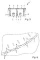
- Such a display instrument is from the JP 2004 161 151 A known and in Fig. 5 shown.
- the known display instrument is designated in its entirety by the reference numeral 1.
- the display instrument 1 comprises a printed circuit board 2, on which a plurality of light emitting diodes 3 are arranged and contacted as light sources next to each other.
- Each of the LEDs 3 is associated with a light field 4, which can be lit by the light emitted by the LEDs 3 light.
- the left LED 3 is turned on, so that the left light field 4 is lit, while the right light field 4 should appear dark.
- the present invention is therefore based on the object to propose a display instrument, in which on the one hand crosstalk of light is prevented and on the other hand, the individual light fields directly adjoin one another.
- the display instrument according to the invention is based on the Fig. 1 to 4 explained in more detail, where it is designated in its entirety by the reference numeral 10.
- the display instrument 10 has a printed circuit board 11, on the side by side a plurality of light-emitting diodes (LEDs) 12 are arranged and contacted as light sources.
- Each light source 12 is associated with a light guide 13 made of a transparent material, for example glass or plastic.
- the light guides 13 each have a light entry surface 14 and a light exit surface 15.
- a main emission direction 16 of the LEDs 12 extends in the illustrated example vertically upwards and perpendicular to the entry surface 14 of the associated light guide 13. Of course, more than one LED 12 per light guide 13 may be provided.
- the light guides 13 are arranged side by side. Each of the light fields 17 of the display instrument 10 is associated with exactly one light guide 13.
- the at least one light source 12 assigned to the respective light field 17 couples in light via the light entry surface 14 of the light guide 13 into this light source.
- the light exit surface 15 of the light guide 13, via which decouples light from the light guide 13, forms the respective light field to be illuminated 17.
- a dial 18 of an instrument is arranged, in which the display instrument 10 is integrated.
- the instrument can Be part of a dashboard of the motor vehicle.
- the dial 18 is either entirely transparent or has transparent portions through which the light coupled out of the light guides 13 can pass.
- a transparent area of a panel 18 'of the dashboard may be provided if the display instrument 10 is not integrated into an instrument. This may, for example, be the case in an air conditioning or heating control, where the display instrument 10 indicates a set temperature or a set blower level. Between the light exit surfaces 15 of the light guide 13 and the dial 18 or the aperture 18 ', an adhesive layer 19 may be provided.
- the coupled into the light guide 13 light is propagated by total reflection in the direction of the light exit surface 15 and thus the illuminated light field 17 in the light guide 13.
- a substantially larger portion of light is directed in the direction of the light field 17, as in the prior art without partitions 5 (see. Fig. 5 ) between the light sources 3 and the light fields 4 is possible.
- Crosstalk of light is prevented in the invention, since the total reflecting sidewalls 20 of the optical fibers 13 prevent too much light from entering the adjacent optical fibers 13.
- the absence of partitions 5 ensures that the light fields 17 can be arranged particularly close together. The result of closely juxtaposed, directly adjacent light fields 17 without dark areas 6 between the light fields 17 can 3 and 4 be removed.
- the light guides 13 preferably have the shape of cuboid block optics, wherein a bottom of the Cuboid, the light entrance surface 14 and an opposite upper side, the light exit surface 15 and thus the light field 17 forms.
- the lateral surfaces 20 of the cuboid 13 between the inlet and the outlet surface 14, 15 form totally reflecting boundary surfaces of the light guide 13.
- the light exit surface 15 may be curved, so that the adjacent light fields 17 form an arc section (see. Fig. 3 ).
- the light exit surface 15 may be flat or curved.
- a lateral edge of the light exit surface 15 may have a different dimension than the opposite edge of the exit surface 15, so that there is an arbitrarily shaped quadrangular light field 17 (eg in the form of a trapezoid).
- the totally reflective side surfaces 20 may be oriented orthogonal to the exit surface 15 or at any other angle thereto.
- the light exit surfaces 15 of the individual light guides 13 may be shaped differently and / or have different dimensions.
- a scale 21 with or without labeling of predefined values for the operating state of the motor vehicle may be arranged (eg tank empty, 1 ⁇ 2 full and full, indication of speed values, indication of speed values, etc.) to read the current Operating state easier. This is, for example, in Fig. 3 shown.
- An air gap (not shown) may be formed between the juxtaposed light guides 13.
- This air gap causes the side walls 20 of the optical waveguide 13 to reflect the injected light in a particularly efficient way, without an excessively large part of the optical waveguide 13 being totally efficiently reflected Light is coupled out laterally and possibly coupled into adjacent light guide 13.
- the air gap can also be designed very thin, for example. ⁇ 1mm.
- the light guides 13 would have a slight funnel shape with an entrance surface 14 which is smaller than the exit surface 15.
- a reflective film (not shown) is arranged as a delimitation of adjacent light guides 13.
- a reflective film may be provided instead of or in addition to the air gap between the optical fibers 13.
- the specular foil can couple light rays, which unintentionally decouple laterally from the light guide 13, because the conditions for total reflection in the light guide 13 are not met, back into the light guide 13, which leads to an improvement in the efficiency of the display instrument 10.
- the opaque film prevents crosstalk of light from a light guide 13 in an adjacent light guide 13. The film is so thin that a viewer of the illuminated light fields 17 no dark, unlit areas between adjacent light fields 17 detects (see. Fig. 4 ).
- the light sources 12 can emit light of different colors. This makes it possible to produce in different colors luminous light fields 17, the different values of an operating state of the Motor vehicle different intensively and subjectively perceptible to view the viewer.
- the present invention results in particularly sharply delimited light fields 17, which shine in clearly distinguishable colors and over their entire surface homogeneously and in the same color.
- a top view of the display instrument 10 is shown as perceived by a viewer.
- eight light fields 17 are arranged next to each other.
- the display instrument 10 has eight juxtaposed light sources 12 and light guide 13.
- the injected light is emitted.
- an opaque aperture element may be arranged which limits an illuminated area 22 of the light fields 17 to the outer edge of the display instrument 10.
- the exit surfaces 15 of the light guide 13 laterally close, preferably immediately adjacent to each other.
Landscapes
- Engineering & Computer Science (AREA)
- Mechanical Engineering (AREA)
- Chemical & Material Sciences (AREA)
- Combustion & Propulsion (AREA)
- Transportation (AREA)
- Physics & Mathematics (AREA)
- General Physics & Mathematics (AREA)
- Details Of Measuring Devices (AREA)
- Instrument Panels (AREA)
Abstract
Description
- Die vorliegende Erfindung betrifft ein Anzeigeinstrument zur Anzeige eines Betriebszustands eines Kraftfahrzeugs mittels mehrerer nebeneinander angeordneter Lichtfelder, die im Blickbereich einer Person an Bord des Kraftfahrzeugs angeordnet sind. Jedem der Lichtfelder ist mindestens eine Lichtquelle zugeordnet, die Licht zum Ausleuchten des Lichtfelds aussendet.
- Aus dem Stand der Technik sind solche Anzeigeinstrumente für Kraftfahrzeuge in unterschiedlichen Ausführungsformen bekannt. Sie werden in modernen Fahrzeugen zur Anzeige eines Betriebszustands des Kraftfahrzeugs verwendet. So können die bekannten Anzeigeinstrumente bspw. zur Anzeige eines Füllstands eines Kraftstofftanks des Kraftfahrzeugs, eines Ladezustands einer Batterie des Kraftfahrzeugs, einer Geschwindigkeit des Kraftfahrzeugs, einer Drehzahl eines Motors des Kraftfahrzeugs, eines Niveaus einer eingestellten Leuchtweite von Scheinwerfern des Kraftfahrzeugs, einer eingestellten Temperatur oder einer eingestellten Stufe eines Gebläses einer Heizungsanlage genutzt werden. Der aktuelle Wert des Betriebszustands wird dabei nicht über einen Zeiger, sondern über eine Aktivierung bzw. Deaktivierung eines oder mehrerer Lichtfelder des Anzeigeinstruments angezeigt.
- Ein Problem der bekannten Anzeigeinstrumente ist das Übersprechen von Licht von einer einem bestimmte Lichtfeld zugeordneten Lichtquelle zu einem benachbarten Lichtfeld. Das führt dazu, dass in den Fällen, wo eigentlich nur ein bestimmtes oder mehrere bestimmte Lichtfelder leuchten sollen, auch Licht von der oder den aktivierten Lichtquelle(n) zu den benachbarten Lichtfeldern gelangt, die eigentlich nicht leuchten sollten, und diese eigentlich inaktiven Lichtfelder zumindest etwas und zu den beleuchteten Lichtfeldern hin leuchten. Das ist nicht nur störend, sondern führt auch dazu, dass der aktuelle Betriebszustand des Kraftfahrzeugs von den Personen an Bord des Fahrzeugs schlecht und nicht auf den ersten Blick erfasst werden kann.
- Bei mehreren beleuchteten benachbarten Lichtfeldern führt das Übersprechen von Licht zudem zu einem Problem bei den beleuchteten Lichtfeldern, wenn die diesen zugeordneten Lichtquellen Licht unterschiedlicher Farben aussenden. Dabei kann die Lichtfarbe eines in einer bestimmten Farbe leuchtenden Lichtfelds durch das andersfarbige Licht einer Lichtquelle, die einem benachbarten Lichtfeld zugeordnet ist, verfälscht werden. Ein Lichtfeld, dessen Lichtquelle rotes Licht aussendet, kann somit bspw. durch gelbes Licht einer benachbarten Lichtquelle zumindest am Rand zu dem der gelben Lichtquelle zugeordneten Lichtfeld hin, orange leuchten. Das führt zu einem Verwischen der Lichtfarben der einzelnen Leuchtfelder.
- Um dies zu verhindern, wird in der
JP 2004 161 151 A - Ausgehend von dem beschriebenen Stand der Technik liegt der vorliegenden Erfindung somit die Aufgabe zugrunde, ein Anzeigeinstrument vorzuschlagen, bei dem einerseits ein Übersprechen von Licht verhindert wird und andererseits die einzelnen Lichtfelder unmittelbar aneinander grenzen.
- Zur Lösung dieser Aufgabe wird ausgehend von dem Anzeigeinstrument der eingangs genannten Art vorgeschlagen, dass das Anzeigeinstrument mehrere nebeneinander angeordnete Lichtleiter aufweist, wobei jedem der Lichtfelder genau ein Lichtleiter zugeordnet ist, in den die mindestens eine dem jeweiligen Lichtfeld zugeordnete Lichtquelle Licht über eine Lichteintrittsfläche des Lichtleiters in diesen einkoppelt, und wobei eine Lichtaustrittsfläche des Lichtleiters, über die Licht aus dem Lichtleiter auskoppelt, das jeweilige Lichtfeld bildet.
- Der Lichtleiter ist zwischen der mindestens einen den einzelnen Lichtfeldern zugeordneten Lichtquelle und den einzelnen Lichtfeldern angeordnet. Er besteht aus einem für das Licht transparenten Material, insbesondere Glas oder Kunststoff. Vorzugsweise sind genauso viele Lichtleiter vorgesehen wie Lichtfelder in dem Anzeigeinstrument vorgesehen sind. Eine Lichteintrittsfläche eines Lichtleiters ist in Richtung der mindestens einen zugeordneten Lichtquelle ausgerichtet, um einen möglichst großen Anteil des ausgesandten Lichts zu erfassen. Um die Einkopplung des Lichts in den Lichtleiter besonders effizient auszugestalten, kann an der Eintrittsfläche eine Einkoppeloptik ausgebildet oder angeordnet sein.
- Das in den Lichtleiter eingekoppelte Licht wird mittels Totalreflexion in Richtung der Lichtaustrittsfläche und damit des Lichtfelds in dem Lichtleiter propagiert. Dabei wird ein wesentlich größerer Teil an Licht in Richtung des Lichtfeldes geleitet, als dies im Stand der Technik ohne Trennwände zwischen den Lichtquellen und Lichtfeldern möglich ist. Ein Übersprechen von Licht wird bei der Erfindung verhindert, da die totalreflektierenden Seitenwände der Lichtleiter verhindern, dass zu viel Licht in die benachbarten Lichtleiter gelangt. Zudem sorgt der Verzicht auf Trennwände dafür, dass die Lichtfelder besonders dicht nebeneinander angeordnet werden können.
- Die Lichtleiter haben vorzugsweise die Form von quaderförmigen Blockoptiken, wobei eine Seite des Quaders die Lichteintrittsfläche und eine gegenüberliegende Seite die Lichtaustrittsfläche und damit das Lichtfeld bildet. Die seitlichen Flächen des Quaders zwischen der Eintritts- und der Austrittsfläche bilden totalreflektierende Begrenzungsflächen des Lichtleiters. Die Lichtaustrittsfläche kann gebogen sein und/oder auf einer Seite eine andere Abmessung aufweisen als auf einer gegenüberliegenden Seite. Die totalreflektierenden Seitenflächen können orthogonal zu den Seiten der Austrittfläche oder in einem beliebig anderen Winkel dazu ausgerichtet sein. Die Lichtaustrittsflächen der einzelnen Lichtfelder können unterschiedlich geformt sein und/oder unterschiedliche Abmessungen aufweisen.
- Neben den Lichtfeldern kann eine Skala mit oder ohne Beschriftung von vorgegebenen Werten für den Betriebszustand des Kraftfahrzeugs angeordnet sein (z.B. Tank leer, ½ voll und ganz voll; Angabe von Geschwindigkeitswerten; Angabe von Drehzahlwerten; etc.), um das Ablesen des aktuellen Betriebszustands zu erleichtern.
- Gemäß einer vorteilhaften Weiterbildung der vorliegenden Erfindung wird vorgeschlagen, dass die Lichtaustrittsflächen nebeneinander angeordneter Lichtleiter unmittelbar aneinander grenzen. Damit kann erreicht werden, dass die Lichtfelder ohne dunkle Zwischenräume unmittelbar aneinander grenzen, ohne dass es zu einem Übersprechen von Licht zwischen den benachbarten Lichtfeldern käme.
- Gemäß einer bevorzugten Ausführungsform wird vorgeschlagen, dass zwischen nebeneinander angeordneten Lichtleitern ein Luftspalt ausgebildet ist. Dieser Luftspalt führt dazu, dass die Seitenwände des Lichtleiters das eingekoppelte Licht besonders effizient totalreflektieren, ohne dass ein übermäßig großer Teil des Lichts seitlich ausgekoppelt und evtl. in benachbarte Lichtleiter eingekoppelt wird. Der Luftspalt kann auch sehr dünn ausgestaltet sein, bspw. <1mm. Ferner ist es denkbar, dass zwar die Seitenwände der benachbarten Lichtleiter zwar durch einen Luftspalt voneinander getrennt sind, dass aber die Lichtaustrittsflächen von benachbarten Lichtleitern seitlich unmittelbar aneinander grenzen. In diesem Fall hätten die Lichtleiter eine leichte Trichterform mit einer Eintrittsfläche, die kleiner als die Austrittsfläche ist. Gemäß einer anderen bevorzugten Ausführungsform wird vorgeschlagen, dass zwischen den nebeneinander angeordneten Lichtleitern eine spiegelnde Folie als Abgrenzung von benachbarten Lichtleitern gegeneinander angeordnet ist. Eine solche spiegelnde Folie kann statt oder zusätzlich zu dem Luftspalt zwischen den Lichtleitern vorgesehen sein. Die spiegelnde Folie kann Lichtstrahlen, die unbeabsichtigt seitlich aus dem Lichtleiter auskoppeln, weil die Bedingungen für eine Totalreflexion im Lichtleiter nicht erfüllt sind, wieder zurück in den Lichtleiter koppeln, was zu einer Verbesserung des Wirkungsgrads des Anzeigeinstruments führt, da ein größerer Anteil des von den Lichtquellen erzeugten Lichts zur Ausleuchtung der Lichtfelder zur Verfügung steht. Die lichtundurchlässige Folie verhindert ein Übersprechen von Licht aus einem Lichtleiter in einen benachbarten Lichtleiter. Die Folie ist so dünn, dass ein Betrachter der ausgeleuchteten Lichtfelder keine dunklen, unbeleuchteten Bereiche (z.B. Stege) zwischen benachbarten Lichtfeldern erkennt.
- Um den Aufbau einfach und die Kosten für das Anzeigeinstrument niedrig zu halten, wird vorgeschlagen, dass jedem der Lichtfelder genau eine Lichtquelle zugeordnet ist. Die Lichtquellen sind vorzugsweise als Halbleiterlichtquellen, insbesondere als Leuchtdioden (LEDs) ausgebildet. Leuchtdioden strahlen Licht in eine Hauptabstrahlrichtung in einen üblicherweise 180°-Halbraum aus. Die Hauptabstrahlrichtung ist vorzugsweise senkrecht zu der Eintrittsfläche des Lichtleiters ausgerichtet. Durch geeignete Einkoppeloptiken kann praktisch das gesamte von einer Leuchtdiode ausgesandte Licht erfasst und in den zugeordneten Lichtleiter eingekoppelt werden. Dadurch ergibt sich eine Steigerung des Wirkungsgrads des Anzeigeinstruments. Es können auch LEDs verwendet werden, die einen Streuwinkel von etwa 120° aufweisen. In diesem Fall kann auch ohne Einkoppeloptiken ein recht guter Wirkungsgrad erzielt werden, da praktisch das gesamte von den LEDs ausgesandte Licht auf die Eintrittsflächen der zugeordneten Lichtleiter fällt und eingekoppelt wird.
- Die Lichtquellen können Licht unterschiedlicher Farben aussenden. Dadurch ist es möglich, in unterschiedlichen Farben leuchtende Lichtfelder zu erzeugen, die unterschiedliche Werte eines Betriebszustands des Kraftfahrzeugs unterschiedlich intensiv und subjektiv wahrnehmbar für den Betrachter anzeigen können. So ist es bspw. denkbar, den Füllstand eines Kraftfahrzeugtanks bis zu einem halb vollen Tank mit weißen Lichtfeldern anzuzeigen, einen Füllstand von einem halb vollen bis zu einem nur noch ein Viertel vollen Tank mit gelben Lichtfeldern, einen Füllstand von unterhalb einem Viertel vollen Tank mit orangen Lichtfeldern, und einen fast leeren Tank (in Reserve) mit roten Lichtfeldern. In entsprechender Weise könnte auch eine Drehzahl des Motors eines Kraftfahrzeugs oder ein beliebig anderer Betriebszustand des Fahrzeugs angezeigt werden. Durch die vorliegende Erfindung ergeben sich besonders scharf voneinander abgegrenzte Lichtfelder, die in deutlich unterscheidbaren Farben und über ihre gesamte Fläche homogen und in der gleichen Farbe leuchten.
- Vorteilhafterweise ist das erfindungsgemäße Anzeigeinstrument zur Anzeige eines Füllstands eines Kraftstofftanks des Kraftfahrzeugs, eines Ladezustands einer Batterie des Kraftfahrzeugs, einer Geschwindigkeit des Kraftfahrzeugs, einer Drehzahl eines Motors des Kraftfahrzeugs, eines Niveaus einer eingestellten Leuchtweite von Scheinwerfern des Kraftfahrzeugs, einer eingestellten Temperatur oder einer eingestellten Stufe eines Gebläses einer Heizungsanlage ausgebildet.
- Ein bevorzugtes Ausführungsbeispiel der Erfindung wird nachfolgend anhand der Figuren näher erläutert. Es zeigen:
-
Fig. 1 ein erfindungsgemäßes Anzeigeinstrument in einer schematischen Schnittansicht; -
Fig. 2 ein erfindungsgemäßes Anzeigeinstrument in einer schematischen Draufsicht; -
Fig. 3 ein erfindungsgemäßes Anzeigeinstrument in einem Armaturenbrett eines Kraftfahrzeugs; -
Fig. 4 das Anzeigeinstrument ausFig. 3 in vergrößerter Ansicht; -
Fig. 5 ein aus dem Stand der Technik bekanntes Anzeigeinstrument; und -
Fig. 6 ein aus dem Stand der Technik bekanntes Anzeigeinstrument in einem Armaturenbrett eines Kraftfahrzeugs. - Die vorliegende Erfindung betrifft ein Anzeigeinstrument zur Anzeige eines Betriebszustands eines Kraftfahrzeugs mittels mehrerer nebeneinander angeordneter Lichtfelder, die im Blickbereich einer Person an Bord des Kraftfahrzeugs angeordnet sind. Jedem der Lichtfelder ist mindestens eine Lichtquelle zugeordnet, die Licht zum Ausleuchten des Lichtfelds aussendet.
- Ein solches Anzeigeinstrument ist aus der
JP 2004 161 151 A Fig. 5 dargestellt. Das bekannte Anzeigeinstrument ist in seiner Gesamtheit mit dem Bezugszeichen 1 bezeichnet. Das Anzeigeinstrument 1 umfasst eine Leiterplatte 2, auf der nebeneinander mehrere Leuchtdioden 3 als Lichtquellen angeordnet und kontaktiert sind. Jeder der LEDs 3 ist ein Lichtfeld 4 zugeordnet, das durch das von den LEDs 3 ausgesandte Licht zum Leuchten gebracht werden kann. In dem dargestellten Beispiel ist die linke LED 3 eingeschaltet, so dass das linke Lichtfeld 4 leuchtet, während das rechte Lichtfeld 4 dunkel erscheinen sollte. - Um ein Übersprechen von Licht aus dem einen (linken) Lichtfeld 4 in ein benachbartes (das rechte) Lichtfeld 4 zu verhindern, wird im Stand der Technik vorgeschlagen, zwischen den einzelnen Lichtfeldern 4 und den diesen zugeordneten Lichtquellen 3 Trennwände 5 vorzusehen, die verhindern, dass von einer Lichtquelle 3 ausgesandtes Licht auf ein benachbartes Lichtfeld 4 fällt. Das hat jedoch den Nachteil, dass zwischen den einzelnen Lichtfeldern 4 relativ große Abstandsbereiche 6 sichtbar sind, die zwischen den Lichtfeldern 4 ausgebildet sind, um die Trennwände 5 zu kaschieren. Die Abstandsbereiche 6 erscheinen einem Betrachter als dunkle Stege zwischen den beleuchteten Lichtfeldern 4, wie man
Fig. 6 entnehmen kann. Ausgehend von dem beschriebenen Stand der Technik liegt der vorliegenden Erfindung somit die Aufgabe zugrunde, ein Anzeigeinstrument vorzuschlagen, bei dem einerseits ein Übersprechen von Licht verhindert wird und andererseits die einzelnen Lichtfelder unmittelbar aneinander grenzen. Das erfindungsgemäße Anzeigeinstrument wird anhand derFig. 1 bis 4 näher erläutert, wo es in seiner Gesamtheit mit dem Bezugszeichen 10 bezeichnet ist. - Das Anzeigeinstrument 10 verfügt über eine Leiterplatte 11, auf der nebeneinander mehrere Leuchtdioden (LEDs) 12 als Lichtquellen angeordnet und kontaktiert sind. Jeder Lichtquelle 12 ist ein Lichtleiter 13 aus einem transparenten Material, bspw. Glas oder Kunststoff, zugeordnet. Die Lichtleiter 13 weisen jeweils eine Lichteintrittsfläche 14 und eine Lichtaustrittsfläche 15 auf. Eine Hauptabstrahlrichtung 16 der LEDs 12 verläuft in dem dargestellten Beispiel senkrecht nach oben und senkrecht zu der Eintrittsfläche 14 des zugeordneten Lichtleiters 13. Selbstverständlich können auch mehr als eine LED 12 pro Lichtleiter 13 vorgesehen sein.
- Die Lichtleiter 13 sind nebeneinander angeordnet. Jedem der Lichtfelder 17 des Anzeigeinstruments 10 ist genau ein Lichtleiter 13 zugeordnet. Die mindestens eine dem jeweiligen Lichtfeld 17 zugeordnete Lichtquelle 12 koppelt Licht über die Lichteintrittsfläche 14 des Lichtleiters 13 in diesen ein. Die Lichtaustrittsfläche 15 des Lichtleiters 13, über die Licht aus dem Lichtleiter 13 auskoppelt, bildet das jeweilige auszuleuchtende oder ausgeleuchtete Lichtfeld 17. In Lichtaustrittsrichtung des aus den Lichtleitern 13 ausgekoppelten Lichts ist ein Ziffernblatt 18 eines Instruments angeordnet, in welches das Anzeigeinstrument 10 integriert ist. Das Instrument kann Teil eines Armaturenbretts des Kraftfahrzeugs sein. Das Ziffernblatt 18 ist entweder insgesamt transparent oder weist transparente Abschnitte auf, durch die das aus den Lichtleitern 13 ausgekoppelte Licht hindurchtreten kann. Alternativ kann statt des Ziffernblatts 18 auch ein transparenter Bereich einer Blende 18' des Armaturenbretts vorgesehen sein, falls das Anzeigeinstrument 10 nicht in ein Instrument integriert ist. Das kann bspw. bei einer Klima- oder Heizungsregelung der Fall sein, wo das Anzeigeinstrument 10 eine eingestellte Temperatur oder eine eingestellte Gebläsestufe anzeigt. Zwischen den Lichtaustrittsflächen 15 der Lichtleiter 13 und dem Ziffernblatt 18 oder der Blende 18' kann eine Klebeschicht 19 vorgesehen sein.
- Das in die Lichtleiter 13 eingekoppelte Licht wird mittels Totalreflexion in Richtung der Lichtaustrittsfläche 15 und damit des ausgeleuchteten Lichtfelds 17 in dem Lichtleiter 13 propagiert. Dabei wird ein wesentlich größerer Teil an Licht in Richtung des Lichtfeldes 17 geleitet, als dies im Stand der Technik ohne Trennwände 5 (vgl.
Fig. 5 ) zwischen den Lichtquellen 3 und den Lichtfeldern 4 möglich ist. Ein Übersprechen von Licht wird bei der Erfindung verhindert, da die totalreflektierenden Seitenwände 20 der Lichtleiter 13 verhindern, dass zu viel Licht in die benachbarten Lichtleiter 13 gelangt. Zudem sorgt der Verzicht auf Trennwände 5 dafür, dass die Lichtfelder 17 besonders dicht nebeneinander angeordnet werden können. Das Ergebnis mit dicht nebeneinander liegenden, unmittelbar aneinander grenzenden Lichtfeldern 17 ohne dunkle Bereiche 6 zwischen den Lichtfeldern 17 kann denFig. 3 und 4 entnommen werden. - Die Lichtleiter 13 haben vorzugsweise die Form von quaderförmigen Blockoptiken, wobei eine Unterseite des Quaders die Lichteintrittsfläche 14 und eine gegenüberliegende Oberseite die Lichtaustrittsfläche 15 und damit das Lichtfeld 17 bildet. Die seitlichen Flächen 20 des Quaders 13 zwischen der Eintritts- und der Austrittsfläche 14, 15 bilden totalreflektierende Begrenzungsflächen des Lichtleiters 13. Die Lichtaustrittsfläche 15 kann gebogen sein, so dass die nebeneinander liegenden Lichtfelder 17 einen Bogenabschnitt bilden (vgl.
Fig. 3 ). Die Lichtaustrittsfläche 15 kann eben oder gewölbt ausgebildet sein. Ein seitlicher Rand der Lichtaustrittsfläche 15 kann eine andere Abmessung aufweisen als der gegenüberliegende Rand der Austrittsfläche 15, so dass sich ein beliebig geformtes viereckiges Lichtfeld 17 (z.B. in der Form eines Trapezes) ergibt. Die totalreflektierenden Seitenflächen 20 können orthogonal zu der Austrittfläche 15 oder in einem beliebig anderen Winkel dazu ausgerichtet sein. Die Lichtaustrittsflächen 15 der einzelnen Lichtleiter 13 können unterschiedlich geformt sein und/oder unterschiedliche Abmessungen aufweisen. - Neben den Lichtfeldern 17 kann eine Skala 21 mit oder ohne Beschriftung von vorgegebenen Werten für den Betriebszustand des Kraftfahrzeugs angeordnet sein (z.B. Tank leer, ½ voll und ganz voll; Angabe von Geschwindigkeitswerten; Angabe von Drehzahlwerten; etc.), um das Ablesen des aktuellen Betriebszustands zu erleichtern. Dies ist bspw. in
Fig. 3 gezeigt. - Zwischen den nebeneinander angeordneten Lichtleitern 13 kann ein Luftspalt (nicht dargestellt) ausgebildet sein. Dieser Luftspalt führt dazu, dass die Seitenwände 20 des Lichtleiters 13 das eingekoppelte Licht besonders effizient totalreflektieren, ohne dass ein übermäßig großer Teil des Lichts seitlich ausgekoppelt und evtl. in benachbarte Lichtleiter 13 eingekoppelt wird. Der Luftspalt kann auch sehr dünn ausgestaltet sein, bspw. <1mm. Ferner ist es denkbar, dass zwar die Seitenwände 20 der benachbarten Lichtleiter 13 zwar durch einen Luftspalt voneinander getrennt sind, dass aber die Lichtaustrittsflächen 15 von benachbarten Lichtleitern 13 seitlich unmittelbar aneinander grenzen. In diesem Fall hätten die Lichtleiter 13 eine leichte Trichterform mit einer Eintrittsfläche 14, die kleiner als die Austrittsfläche 15 ist.
- Alternativ oder zusätzlich ist es möglich, dass zwischen den nebeneinander angeordneten Lichtleitern 13 entlang ihrer Seitenflächen 20 eine spiegelnde Folie (nicht dargestellt) als Abgrenzung von benachbarten Lichtleitern 13 angeordnet ist. Eine solche spiegelnde Folie kann statt oder zusätzlich zu dem Luftspalt zwischen den Lichtleitern 13 vorgesehen sein. Die spiegelnde Folie kann Lichtstrahlen, die unbeabsichtigt seitlich aus dem Lichtleiter 13 auskoppeln, weil die Bedingungen für eine Totalreflexion im Lichtleiter 13 nicht erfüllt sind, wieder zurück in den Lichtleiter 13 koppeln, was zu einer Verbesserung des Wirkungsgrads des Anzeigeinstruments 10 führt. Die lichtundurchlässige Folie verhindert ein Übersprechen von Licht aus einem Lichtleiter 13 in einen benachbarten Lichtleiter 13. Die Folie ist so dünn, dass ein Betrachter der ausgeleuchteten Lichtfelder 17 keine dunklen, unbeleuchteten Bereiche zwischen benachbarten Lichtfeldern 17 erkennt (vgl.
Fig. 4 ). - Die Lichtquellen 12 können Licht unterschiedlicher Farben aussenden. Dadurch ist es möglich, in unterschiedlichen Farben leuchtende Lichtfelder 17 zu erzeugen, die unterschiedliche Werte eines Betriebszustands des Kraftfahrzeugs unterschiedlich intensiv und subjektiv wahrnehmbar für den Betrachter anzeigen können. Durch die vorliegende Erfindung ergeben sich besonders scharf voneinander abgegrenzte Lichtfelder 17, die in deutlich unterscheidbaren Farben und über ihre gesamte Fläche homogen und in der gleichen Farbe leuchten.
- In
Fig. 2 ist eine Draufsicht auf das Anzeigeinstrument 10 gezeigt, wie es von einem Betrachter wahrgenommen wird. In diesem Beispiel sind acht Lichtfelder 17 nebeneinander angeordnet. Dementsprechend verfügt das Anzeigeinstrument 10 über acht nebeneinander angeordnete Lichtquellen 12 und Lichtleiter 13. Über die Lichtaustrittsflächen 15 der Lichtleiter 13 wird das eingekoppelte Licht abgestrahlt. In Lichtaustrittsrichtung des aus den Austrittsflächen 15 ausgekoppelten Lichts kann ein lichtundurchlässiges Blendenelement angeordnet sein, das einen ausgeleuchteten Bereich 22 der Lichtfelder 17 zum äußeren Rand des Anzeigeinstruments 10 hin begrenzt. Auch hier grenzen die Austrittsflächen 15 der Lichtleiter 13 seitlich dicht, vorzugsweise unmittelbar aneinander.
Claims (8)
- Anzeigeinstrument (10) zur Anzeige eines Betriebszustands eines Kraftfahrzeugs mittels mehrerer neben einander angeordneter Lichtfelder (17), die im Blickbereich einer Person an Bord des Kraftfahrzeugs angeordnet sind, wobei jedem der Lichtfelder (17) mindestens eine Lichtquelle (12) zugeordnet ist, die Licht zum Ausleuchten des Lichtfelds (17) aussendet, dadurch gekennzeichnet, dass das Anzeigeinstrument (10) mehrere nebeneinander angeordnete Lichtleiter (13) aufweist, wobei jedem der Lichtfelder (17) genau ein Lichtleiter (13) zugeordnet ist, in den die mindestens eine dem jeweiligen Lichtfeld (17) zugeordnete Lichtquelle (12) Licht über eine Lichteintrittsfläche (14) des Lichtleiters (13) in diesen einkoppelt, und wobei eine Lichtaustrittsfläche (15) des Lichtleiters (13), über die Licht aus dem Lichtleiter (13) auskoppelt, das jeweilige Lichtfeld (17) bildet.
- Anzeigeinstrument (10) nach Anspruch 1, dadurch gekennzeichnet, dass die Lichtaustrittsflächen (15) nebeneinander angeordneter Lichtleiter (13) unmittelbar aneinander grenzen.
- Anzeigeinstrument (10) nach Anspruch 1 oder 2, dadurch gekennzeichnet, dass zwischen nebeneinander angeordneten Lichtleitern (13) ein Luftspalt ausgebildet ist.
- Anzeigeinstrument (10) nach einem der Ansprüche 1 bis 3, dadurch gekennzeichnet, dass zwischen den nebeneinander angeordneten Lichtleitern (13) eine spiegelnde Folie als Abgrenzung von benachbarten Lichtleitern (13) angeordnet ist.
- Anzeigeinstrument (10) nach einem der Ansprüche 1 bis 4, dadurch gekennzeichnet, dass jedem der Lichtfelder (17) genau eine Lichtquelle (12) zugeordnet ist.
- Anzeigeinstrument (10) nach einem der Ansprüche 1 bis 5, dadurch gekennzeichnet, dass die Lichtquellen (12) als Halbleiterlichtquellen, insbesondere als Leuchtdioden ausgebildet sind.
- Anzeigeinstrument (10) nach einem der Ansprüche 1 bis 6, dadurch gekennzeichnet, dass die Lichtquellen (12) Licht unterschiedlicher Farben aussenden.
- Anzeigeinstrument (10) nach einem der Ansprüche 1 bis 7, dadurch gekennzeichnet, dass das Anzeigeinstrument (10) zur Anzeige eines Füllstands eines Kraftstofftanks des Kraftfahrzeugs, eines Ladezustands einer Batterie des Kraftfahrzeugs, einer Geschwindigkeit des Kraftfahrzeugs, einer Drehzahl eines Motors des Kraftfahrzeugs, eines Niveaus einer eingestellten Leuchtweite von Scheinwerfern des Kraftfahrzeugs, einer eingestellten Temperatur oder einer eingestellten Stufe eines Gebläses einer Heizungsanlage ausgebildet ist.
Applications Claiming Priority (1)
| Application Number | Priority Date | Filing Date | Title |
|---|---|---|---|
| DE102014227028.6A DE102014227028A1 (de) | 2014-12-30 | 2014-12-30 | Anzeigeinstrument zur Anzeige eines Betriebszustands eines Kraftfahrzeugs |
Publications (3)
| Publication Number | Publication Date |
|---|---|
| EP3040231A2 true EP3040231A2 (de) | 2016-07-06 |
| EP3040231A3 EP3040231A3 (de) | 2017-04-19 |
| EP3040231B1 EP3040231B1 (de) | 2019-07-03 |
Family
ID=54936774
Family Applications (1)
| Application Number | Title | Priority Date | Filing Date |
|---|---|---|---|
| EP15199493.6A Not-in-force EP3040231B1 (de) | 2014-12-30 | 2015-12-11 | Anzeigeinstrument zur anzeige eines betriebszustands eines kraftfahrzeugs |
Country Status (2)
| Country | Link |
|---|---|
| EP (1) | EP3040231B1 (de) |
| DE (1) | DE102014227028A1 (de) |
Cited By (3)
| Publication number | Priority date | Publication date | Assignee | Title |
|---|---|---|---|---|
| JP2016176815A (ja) * | 2015-03-20 | 2016-10-06 | 日本精機株式会社 | 照明装置 |
| EP3460455A3 (de) * | 2017-08-31 | 2019-07-03 | JENETRIC GmbH | Vorrichtung zur kontaktbasierten gleichzeitigen aufnahme von abdrücken von autopodien |
| WO2019137733A1 (de) * | 2018-01-11 | 2019-07-18 | Dr. Schneider Kunststoffwerke Gmbh | Beleuchtungsvorrichtung und verfahren zur herstellung |
Families Citing this family (1)
| Publication number | Priority date | Publication date | Assignee | Title |
|---|---|---|---|---|
| DE102018212886B4 (de) * | 2018-08-02 | 2021-12-02 | Audi Ag | Beleuchtungseinrichtung mit Bildschirm und Lichtleitern zum Darstellen eines Linienlichts; Kraftfahrzeug sowie Verfahren zum Betreiben einer Beleuchtungseinrichtung |
Citations (1)
| Publication number | Priority date | Publication date | Assignee | Title |
|---|---|---|---|---|
| JP2004161151A (ja) | 2002-11-14 | 2004-06-10 | Yns:Kk | 車両用計器盤における光漏れ軽減構造 |
Family Cites Families (5)
| Publication number | Priority date | Publication date | Assignee | Title |
|---|---|---|---|---|
| JPS6019077U (ja) * | 1983-07-18 | 1985-02-08 | 三菱レイヨン株式会社 | 照光式表示装置 |
| DE3602020A1 (de) * | 1986-01-24 | 1987-07-30 | Gaggenau Werke | Schalteinrichtung fuer kuechengeraete, wie kochmulden oder dergleichen |
| DE19519444A1 (de) * | 1995-05-26 | 1996-11-28 | Ernst Bremicker Gmbh & Co Kg | Faseroptische Anzeige |
| JP3608274B2 (ja) * | 1995-11-30 | 2005-01-05 | 豊田合成株式会社 | 車両用メータ |
| DE102010009254A1 (de) * | 2010-02-25 | 2011-08-25 | Bayerische Motoren Werke Aktiengesellschaft, 80809 | Lichtleiteranzeigevorrichtung |
-
2014
- 2014-12-30 DE DE102014227028.6A patent/DE102014227028A1/de not_active Ceased
-
2015
- 2015-12-11 EP EP15199493.6A patent/EP3040231B1/de not_active Not-in-force
Patent Citations (1)
| Publication number | Priority date | Publication date | Assignee | Title |
|---|---|---|---|---|
| JP2004161151A (ja) | 2002-11-14 | 2004-06-10 | Yns:Kk | 車両用計器盤における光漏れ軽減構造 |
Cited By (4)
| Publication number | Priority date | Publication date | Assignee | Title |
|---|---|---|---|---|
| JP2016176815A (ja) * | 2015-03-20 | 2016-10-06 | 日本精機株式会社 | 照明装置 |
| EP3460455A3 (de) * | 2017-08-31 | 2019-07-03 | JENETRIC GmbH | Vorrichtung zur kontaktbasierten gleichzeitigen aufnahme von abdrücken von autopodien |
| US10366273B2 (en) | 2017-08-31 | 2019-07-30 | JENETRIC GmbH | Device for the contact-based simultaneous capture of prints of autopodia |
| WO2019137733A1 (de) * | 2018-01-11 | 2019-07-18 | Dr. Schneider Kunststoffwerke Gmbh | Beleuchtungsvorrichtung und verfahren zur herstellung |
Also Published As
| Publication number | Publication date |
|---|---|
| DE102014227028A1 (de) | 2016-06-30 |
| EP3040231A3 (de) | 2017-04-19 |
| EP3040231B1 (de) | 2019-07-03 |
Similar Documents
| Publication | Publication Date | Title |
|---|---|---|
| DE102008048765B4 (de) | Beleuchtungsvorrichtung für Kraftfahrzeuge | |
| DE102012112151A1 (de) | Kraftfahrzeugrückleuchte | |
| DE102012105095B4 (de) | Reflektorsignalleuchte mit verdeckter Lichtquelle | |
| DE10004972A1 (de) | Anzeigevorrichtung | |
| DE102016110054A1 (de) | Beleuchtungseinrichtung und Interieurteil mit Beleuchtungseinrichtung | |
| WO2016096290A1 (de) | Anzeigevorrichtung zur anzeige zumindest eines symbols, schaltvorrichtung und verfahren zum herstellen einer anzeigevorrichtung | |
| DE102014117842A1 (de) | Zusatzbremsleuchte für Fahrzeuge | |
| EP3040231B1 (de) | Anzeigeinstrument zur anzeige eines betriebszustands eines kraftfahrzeugs | |
| DE102012112152A1 (de) | Kraftfahrzeugrückleuchte | |
| EP2054257A1 (de) | Anzeigevorrichtung für ein kraftfahrzeug mit einem im wesentlichen parallelen lichtbündel | |
| DE102010049408A1 (de) | Innenleuchte für Fahrzeuge | |
| EP1160116A2 (de) | Kombiinstrument für ein Kraftfahrzeug | |
| DE102011000038A1 (de) | Beleuchtungsvorrichtung für Fahrzeuge | |
| DE102017127925B4 (de) | Leuchtvorrichtung, insbesondere eine Signalleuchte, für Kraftfahrzeuge | |
| DE102014113735A1 (de) | Lampenvorrichtung für ein Fahrzeug | |
| DE102010032946A1 (de) | Kraftfahrzeug mit einem Innenraum, in dem eine Beleuchtungseinrichtung angeordnet ist | |
| DE10036323A1 (de) | Leuchte für Fahrzeuge | |
| DE102018003553A1 (de) | Kraftfahrzeugbeleuchtungsmodul | |
| DE102012007227A1 (de) | Beleuchtungsvorrichtung und Fahrzeugleuchte mit einer Beleuchtungsvorrichtung | |
| DE102010012746A1 (de) | Beleuchtungseinrichtung | |
| DE102022127222A1 (de) | Beleuchtungsvorrichtung für Fahrzeuge | |
| DE102011016425A1 (de) | Instrument für ein Kraftfahrzeug | |
| DE102012016771A1 (de) | Instrument mit Ziffernblatt für ein Kraftfahrzeug und Verfahren zur Herstellung desselben | |
| DE102020121803A1 (de) | Kraftfahrzeug mit einem Kühlergrill | |
| DE102013016346A1 (de) | Fahrzeuginnenraum-Bauteil zur Erzeugung einer Ambientebeleuchtung |
Legal Events
| Date | Code | Title | Description |
|---|---|---|---|
| PUAI | Public reference made under article 153(3) epc to a published international application that has entered the european phase |
Free format text: ORIGINAL CODE: 0009012 |
|
| AK | Designated contracting states |
Kind code of ref document: A2 Designated state(s): AL AT BE BG CH CY CZ DE DK EE ES FI FR GB GR HR HU IE IS IT LI LT LU LV MC MK MT NL NO PL PT RO RS SE SI SK SM TR |
|
| AX | Request for extension of the european patent |
Extension state: BA ME |
|
| PUAL | Search report despatched |
Free format text: ORIGINAL CODE: 0009013 |
|
| AK | Designated contracting states |
Kind code of ref document: A3 Designated state(s): AL AT BE BG CH CY CZ DE DK EE ES FI FR GB GR HR HU IE IS IT LI LT LU LV MC MK MT NL NO PL PT RO RS SE SI SK SM TR |
|
| AX | Request for extension of the european patent |
Extension state: BA ME |
|
| RIC1 | Information provided on ipc code assigned before grant |
Ipc: G01D 11/28 20060101ALI20170315BHEP Ipc: B60K 37/02 20060101ALI20170315BHEP Ipc: B60K 35/00 20060101AFI20170315BHEP Ipc: G01D 13/28 20060101ALI20170315BHEP |
|
| STAA | Information on the status of an ep patent application or granted ep patent |
Free format text: STATUS: REQUEST FOR EXAMINATION WAS MADE |
|
| 17P | Request for examination filed |
Effective date: 20170509 |
|
| RBV | Designated contracting states (corrected) |
Designated state(s): AL AT BE BG CH CY CZ DE DK EE ES FI FR GB GR HR HU IE IS IT LI LT LU LV MC MK MT NL NO PL PT RO RS SE SI SK SM TR |
|
| RIN1 | Information on inventor provided before grant (corrected) |
Inventor name: HOSS, CHRISTIAN |
|
| STAA | Information on the status of an ep patent application or granted ep patent |
Free format text: STATUS: EXAMINATION IS IN PROGRESS |
|
| 17Q | First examination report despatched |
Effective date: 20180430 |
|
| 17Q | First examination report despatched |
Effective date: 20180516 |
|
| GRAP | Despatch of communication of intention to grant a patent |
Free format text: ORIGINAL CODE: EPIDOSNIGR1 |
|
| STAA | Information on the status of an ep patent application or granted ep patent |
Free format text: STATUS: GRANT OF PATENT IS INTENDED |
|
| INTG | Intention to grant announced |
Effective date: 20190322 |
|
| GRAS | Grant fee paid |
Free format text: ORIGINAL CODE: EPIDOSNIGR3 |
|
| GRAA | (expected) grant |
Free format text: ORIGINAL CODE: 0009210 |
|
| STAA | Information on the status of an ep patent application or granted ep patent |
Free format text: STATUS: THE PATENT HAS BEEN GRANTED |
|
| AK | Designated contracting states |
Kind code of ref document: B1 Designated state(s): AL AT BE BG CH CY CZ DE DK EE ES FI FR GB GR HR HU IE IS IT LI LT LU LV MC MK MT NL NO PL PT RO RS SE SI SK SM TR |
|
| REG | Reference to a national code |
Ref country code: GB Ref legal event code: FG4D Free format text: NOT ENGLISH |
|
| REG | Reference to a national code |
Ref country code: CH Ref legal event code: EP Ref country code: AT Ref legal event code: REF Ref document number: 1150573 Country of ref document: AT Kind code of ref document: T Effective date: 20190715 |
|
| REG | Reference to a national code |
Ref country code: IE Ref legal event code: FG4D Free format text: LANGUAGE OF EP DOCUMENT: GERMAN |
|
| REG | Reference to a national code |
Ref country code: DE Ref legal event code: R096 Ref document number: 502015009507 Country of ref document: DE |
|
| REG | Reference to a national code |
Ref country code: NL Ref legal event code: MP Effective date: 20190703 |
|
| REG | Reference to a national code |
Ref country code: LT Ref legal event code: MG4D |
|
| PG25 | Lapsed in a contracting state [announced via postgrant information from national office to epo] |
Ref country code: HR Free format text: LAPSE BECAUSE OF FAILURE TO SUBMIT A TRANSLATION OF THE DESCRIPTION OR TO PAY THE FEE WITHIN THE PRESCRIBED TIME-LIMIT Effective date: 20190703 Ref country code: BG Free format text: LAPSE BECAUSE OF FAILURE TO SUBMIT A TRANSLATION OF THE DESCRIPTION OR TO PAY THE FEE WITHIN THE PRESCRIBED TIME-LIMIT Effective date: 20191003 Ref country code: CZ Free format text: LAPSE BECAUSE OF FAILURE TO SUBMIT A TRANSLATION OF THE DESCRIPTION OR TO PAY THE FEE WITHIN THE PRESCRIBED TIME-LIMIT Effective date: 20190703 Ref country code: PT Free format text: LAPSE BECAUSE OF FAILURE TO SUBMIT A TRANSLATION OF THE DESCRIPTION OR TO PAY THE FEE WITHIN THE PRESCRIBED TIME-LIMIT Effective date: 20191104 Ref country code: NL Free format text: LAPSE BECAUSE OF FAILURE TO SUBMIT A TRANSLATION OF THE DESCRIPTION OR TO PAY THE FEE WITHIN THE PRESCRIBED TIME-LIMIT Effective date: 20190703 Ref country code: LT Free format text: LAPSE BECAUSE OF FAILURE TO SUBMIT A TRANSLATION OF THE DESCRIPTION OR TO PAY THE FEE WITHIN THE PRESCRIBED TIME-LIMIT Effective date: 20190703 Ref country code: NO Free format text: LAPSE BECAUSE OF FAILURE TO SUBMIT A TRANSLATION OF THE DESCRIPTION OR TO PAY THE FEE WITHIN THE PRESCRIBED TIME-LIMIT Effective date: 20191003 Ref country code: SE Free format text: LAPSE BECAUSE OF FAILURE TO SUBMIT A TRANSLATION OF THE DESCRIPTION OR TO PAY THE FEE WITHIN THE PRESCRIBED TIME-LIMIT Effective date: 20190703 Ref country code: FI Free format text: LAPSE BECAUSE OF FAILURE TO SUBMIT A TRANSLATION OF THE DESCRIPTION OR TO PAY THE FEE WITHIN THE PRESCRIBED TIME-LIMIT Effective date: 20190703 |
|
| PG25 | Lapsed in a contracting state [announced via postgrant information from national office to epo] |
Ref country code: IS Free format text: LAPSE BECAUSE OF FAILURE TO SUBMIT A TRANSLATION OF THE DESCRIPTION OR TO PAY THE FEE WITHIN THE PRESCRIBED TIME-LIMIT Effective date: 20191103 Ref country code: RS Free format text: LAPSE BECAUSE OF FAILURE TO SUBMIT A TRANSLATION OF THE DESCRIPTION OR TO PAY THE FEE WITHIN THE PRESCRIBED TIME-LIMIT Effective date: 20190703 Ref country code: ES Free format text: LAPSE BECAUSE OF FAILURE TO SUBMIT A TRANSLATION OF THE DESCRIPTION OR TO PAY THE FEE WITHIN THE PRESCRIBED TIME-LIMIT Effective date: 20190703 Ref country code: GR Free format text: LAPSE BECAUSE OF FAILURE TO SUBMIT A TRANSLATION OF THE DESCRIPTION OR TO PAY THE FEE WITHIN THE PRESCRIBED TIME-LIMIT Effective date: 20191004 Ref country code: AL Free format text: LAPSE BECAUSE OF FAILURE TO SUBMIT A TRANSLATION OF THE DESCRIPTION OR TO PAY THE FEE WITHIN THE PRESCRIBED TIME-LIMIT Effective date: 20190703 Ref country code: LV Free format text: LAPSE BECAUSE OF FAILURE TO SUBMIT A TRANSLATION OF THE DESCRIPTION OR TO PAY THE FEE WITHIN THE PRESCRIBED TIME-LIMIT Effective date: 20190703 |
|
| PG25 | Lapsed in a contracting state [announced via postgrant information from national office to epo] |
Ref country code: TR Free format text: LAPSE BECAUSE OF FAILURE TO SUBMIT A TRANSLATION OF THE DESCRIPTION OR TO PAY THE FEE WITHIN THE PRESCRIBED TIME-LIMIT Effective date: 20190703 |
|
| PG25 | Lapsed in a contracting state [announced via postgrant information from national office to epo] |
Ref country code: DK Free format text: LAPSE BECAUSE OF FAILURE TO SUBMIT A TRANSLATION OF THE DESCRIPTION OR TO PAY THE FEE WITHIN THE PRESCRIBED TIME-LIMIT Effective date: 20190703 Ref country code: EE Free format text: LAPSE BECAUSE OF FAILURE TO SUBMIT A TRANSLATION OF THE DESCRIPTION OR TO PAY THE FEE WITHIN THE PRESCRIBED TIME-LIMIT Effective date: 20190703 Ref country code: RO Free format text: LAPSE BECAUSE OF FAILURE TO SUBMIT A TRANSLATION OF THE DESCRIPTION OR TO PAY THE FEE WITHIN THE PRESCRIBED TIME-LIMIT Effective date: 20190703 Ref country code: PL Free format text: LAPSE BECAUSE OF FAILURE TO SUBMIT A TRANSLATION OF THE DESCRIPTION OR TO PAY THE FEE WITHIN THE PRESCRIBED TIME-LIMIT Effective date: 20190703 |
|
| PG25 | Lapsed in a contracting state [announced via postgrant information from national office to epo] |
Ref country code: SM Free format text: LAPSE BECAUSE OF FAILURE TO SUBMIT A TRANSLATION OF THE DESCRIPTION OR TO PAY THE FEE WITHIN THE PRESCRIBED TIME-LIMIT Effective date: 20190703 Ref country code: SK Free format text: LAPSE BECAUSE OF FAILURE TO SUBMIT A TRANSLATION OF THE DESCRIPTION OR TO PAY THE FEE WITHIN THE PRESCRIBED TIME-LIMIT Effective date: 20190703 Ref country code: IS Free format text: LAPSE BECAUSE OF FAILURE TO SUBMIT A TRANSLATION OF THE DESCRIPTION OR TO PAY THE FEE WITHIN THE PRESCRIBED TIME-LIMIT Effective date: 20200224 |
|
| REG | Reference to a national code |
Ref country code: DE Ref legal event code: R097 Ref document number: 502015009507 Country of ref document: DE |
|
| PLBE | No opposition filed within time limit |
Free format text: ORIGINAL CODE: 0009261 |
|
| STAA | Information on the status of an ep patent application or granted ep patent |
Free format text: STATUS: NO OPPOSITION FILED WITHIN TIME LIMIT |
|
| PG2D | Information on lapse in contracting state deleted |
Ref country code: IS |
|
| REG | Reference to a national code |
Ref country code: CH Ref legal event code: PL |
|
| 26N | No opposition filed |
Effective date: 20200603 |
|
| REG | Reference to a national code |
Ref country code: BE Ref legal event code: MM Effective date: 20191231 |
|
| PG25 | Lapsed in a contracting state [announced via postgrant information from national office to epo] |
Ref country code: SI Free format text: LAPSE BECAUSE OF FAILURE TO SUBMIT A TRANSLATION OF THE DESCRIPTION OR TO PAY THE FEE WITHIN THE PRESCRIBED TIME-LIMIT Effective date: 20190703 Ref country code: MC Free format text: LAPSE BECAUSE OF FAILURE TO SUBMIT A TRANSLATION OF THE DESCRIPTION OR TO PAY THE FEE WITHIN THE PRESCRIBED TIME-LIMIT Effective date: 20190703 |
|
| GBPC | Gb: european patent ceased through non-payment of renewal fee |
Effective date: 20191211 |
|
| PG25 | Lapsed in a contracting state [announced via postgrant information from national office to epo] |
Ref country code: IE Free format text: LAPSE BECAUSE OF NON-PAYMENT OF DUE FEES Effective date: 20191211 Ref country code: GB Free format text: LAPSE BECAUSE OF NON-PAYMENT OF DUE FEES Effective date: 20191211 Ref country code: LU Free format text: LAPSE BECAUSE OF NON-PAYMENT OF DUE FEES Effective date: 20191211 |
|
| PG25 | Lapsed in a contracting state [announced via postgrant information from national office to epo] |
Ref country code: BE Free format text: LAPSE BECAUSE OF NON-PAYMENT OF DUE FEES Effective date: 20191231 Ref country code: CH Free format text: LAPSE BECAUSE OF NON-PAYMENT OF DUE FEES Effective date: 20191231 Ref country code: LI Free format text: LAPSE BECAUSE OF NON-PAYMENT OF DUE FEES Effective date: 20191231 |
|
| PG25 | Lapsed in a contracting state [announced via postgrant information from national office to epo] |
Ref country code: CY Free format text: LAPSE BECAUSE OF FAILURE TO SUBMIT A TRANSLATION OF THE DESCRIPTION OR TO PAY THE FEE WITHIN THE PRESCRIBED TIME-LIMIT Effective date: 20190703 |
|
| PG25 | Lapsed in a contracting state [announced via postgrant information from national office to epo] |
Ref country code: HU Free format text: LAPSE BECAUSE OF FAILURE TO SUBMIT A TRANSLATION OF THE DESCRIPTION OR TO PAY THE FEE WITHIN THE PRESCRIBED TIME-LIMIT; INVALID AB INITIO Effective date: 20151211 Ref country code: MT Free format text: LAPSE BECAUSE OF FAILURE TO SUBMIT A TRANSLATION OF THE DESCRIPTION OR TO PAY THE FEE WITHIN THE PRESCRIBED TIME-LIMIT Effective date: 20190703 |
|
| REG | Reference to a national code |
Ref country code: AT Ref legal event code: MM01 Ref document number: 1150573 Country of ref document: AT Kind code of ref document: T Effective date: 20201211 |
|
| PG25 | Lapsed in a contracting state [announced via postgrant information from national office to epo] |
Ref country code: AT Free format text: LAPSE BECAUSE OF NON-PAYMENT OF DUE FEES Effective date: 20201211 |
|
| PG25 | Lapsed in a contracting state [announced via postgrant information from national office to epo] |
Ref country code: MK Free format text: LAPSE BECAUSE OF FAILURE TO SUBMIT A TRANSLATION OF THE DESCRIPTION OR TO PAY THE FEE WITHIN THE PRESCRIBED TIME-LIMIT Effective date: 20190703 |
|
| REG | Reference to a national code |
Ref country code: DE Ref legal event code: R082 Ref document number: 502015009507 Country of ref document: DE Representative=s name: HERRMANN PATENTANWAELTE, DE Ref country code: DE Ref legal event code: R082 Ref document number: 502015009507 Country of ref document: DE Representative=s name: WOERZ PATENTANWAELTE PARTNERSCHAFTSGESELLSCHAF, DE |
|
| REG | Reference to a national code |
Ref country code: DE Ref legal event code: R082 Ref document number: 502015009507 Country of ref document: DE Representative=s name: HERRMANN PATENTANWAELTE, DE |
|
| PGFP | Annual fee paid to national office [announced via postgrant information from national office to epo] |
Ref country code: IT Payment date: 20231228 Year of fee payment: 9 Ref country code: FR Payment date: 20231221 Year of fee payment: 9 Ref country code: DE Payment date: 20231214 Year of fee payment: 9 |
|
| REG | Reference to a national code |
Ref country code: DE Ref legal event code: R119 Ref document number: 502015009507 Country of ref document: DE |
|
| PG25 | Lapsed in a contracting state [announced via postgrant information from national office to epo] |
Ref country code: DE Free format text: LAPSE BECAUSE OF NON-PAYMENT OF DUE FEES Effective date: 20250701 |
|
| PG25 | Lapsed in a contracting state [announced via postgrant information from national office to epo] |
Ref country code: IT Free format text: LAPSE BECAUSE OF NON-PAYMENT OF DUE FEES Effective date: 20241211 |
|
| PG25 | Lapsed in a contracting state [announced via postgrant information from national office to epo] |
Ref country code: FR Free format text: LAPSE BECAUSE OF NON-PAYMENT OF DUE FEES Effective date: 20241231 |