EP3040244A1 - Bilderfassungssystem mit flexiblem übertragungselement - Google Patents
Bilderfassungssystem mit flexiblem übertragungselement Download PDFInfo
- Publication number
- EP3040244A1 EP3040244A1 EP16150134.1A EP16150134A EP3040244A1 EP 3040244 A1 EP3040244 A1 EP 3040244A1 EP 16150134 A EP16150134 A EP 16150134A EP 3040244 A1 EP3040244 A1 EP 3040244A1
- Authority
- EP
- European Patent Office
- Prior art keywords
- image acquisition
- acquisition system
- protective element
- camera
- camera unit
- Prior art date
- Legal status (The legal status is an assumption and is not a legal conclusion. Google has not performed a legal analysis and makes no representation as to the accuracy of the status listed.)
- Granted
Links
- 230000005540 biological transmission Effects 0.000 title claims description 35
- 230000001681 protective effect Effects 0.000 claims abstract description 64
- 230000007246 mechanism Effects 0.000 claims abstract description 24
- 230000008859 change Effects 0.000 claims abstract description 8
- 238000012423 maintenance Methods 0.000 claims description 18
- 238000004140 cleaning Methods 0.000 claims description 17
- 238000003384 imaging method Methods 0.000 claims description 14
- 239000011248 coating agent Substances 0.000 claims description 6
- 238000000576 coating method Methods 0.000 claims description 6
- 238000009434 installation Methods 0.000 abstract description 3
- 230000008901 benefit Effects 0.000 description 8
- 230000007613 environmental effect Effects 0.000 description 6
- 230000007547 defect Effects 0.000 description 3
- 238000013461 design Methods 0.000 description 3
- 229920001343 polytetrafluoroethylene Polymers 0.000 description 3
- 230000008439 repair process Effects 0.000 description 3
- 230000002441 reversible effect Effects 0.000 description 3
- 238000005266 casting Methods 0.000 description 2
- 230000001419 dependent effect Effects 0.000 description 2
- 239000002184 metal Substances 0.000 description 2
- 239000004810 polytetrafluoroethylene Substances 0.000 description 2
- OKTJSMMVPCPJKN-UHFFFAOYSA-N Carbon Chemical compound [C] OKTJSMMVPCPJKN-UHFFFAOYSA-N 0.000 description 1
- 240000006829 Ficus sundaica Species 0.000 description 1
- 229910001335 Galvanized steel Inorganic materials 0.000 description 1
- 230000009471 action Effects 0.000 description 1
- 239000000853 adhesive Substances 0.000 description 1
- 230000001070 adhesive effect Effects 0.000 description 1
- 238000005452 bending Methods 0.000 description 1
- 239000003795 chemical substances by application Substances 0.000 description 1
- 150000001875 compounds Chemical class 0.000 description 1
- 230000000694 effects Effects 0.000 description 1
- 238000004146 energy storage Methods 0.000 description 1
- 238000005516 engineering process Methods 0.000 description 1
- 239000008397 galvanized steel Substances 0.000 description 1
- 229910002804 graphite Inorganic materials 0.000 description 1
- 239000010439 graphite Substances 0.000 description 1
- 238000010438 heat treatment Methods 0.000 description 1
- 238000002347 injection Methods 0.000 description 1
- 239000007924 injection Substances 0.000 description 1
- 239000000314 lubricant Substances 0.000 description 1
- 238000004519 manufacturing process Methods 0.000 description 1
- 239000000463 material Substances 0.000 description 1
- 238000000034 method Methods 0.000 description 1
- 239000004033 plastic Substances 0.000 description 1
- 230000003014 reinforcing effect Effects 0.000 description 1
- 239000007787 solid Substances 0.000 description 1
- 239000010935 stainless steel Substances 0.000 description 1
- 229910001220 stainless steel Inorganic materials 0.000 description 1
- 230000003746 surface roughness Effects 0.000 description 1
- 238000012546 transfer Methods 0.000 description 1
- 238000013519 translation Methods 0.000 description 1
Images


Classifications
-
- B—PERFORMING OPERATIONS; TRANSPORTING
- B60—VEHICLES IN GENERAL
- B60R—VEHICLES, VEHICLE FITTINGS, OR VEHICLE PARTS, NOT OTHERWISE PROVIDED FOR
- B60R11/00—Arrangements for holding or mounting articles, not otherwise provided for
- B60R11/04—Mounting of cameras operative during drive; Arrangement of controls thereof relative to the vehicle
-
- H—ELECTRICITY
- H04—ELECTRIC COMMUNICATION TECHNIQUE
- H04N—PICTORIAL COMMUNICATION, e.g. TELEVISION
- H04N23/00—Cameras or camera modules comprising electronic image sensors; Control thereof
- H04N23/50—Constructional details
- H04N23/51—Housings
-
- H—ELECTRICITY
- H04—ELECTRIC COMMUNICATION TECHNIQUE
- H04N—PICTORIAL COMMUNICATION, e.g. TELEVISION
- H04N23/00—Cameras or camera modules comprising electronic image sensors; Control thereof
- H04N23/50—Constructional details
- H04N23/55—Optical parts specially adapted for electronic image sensors; Mounting thereof
-
- H—ELECTRICITY
- H04—ELECTRIC COMMUNICATION TECHNIQUE
- H04N—PICTORIAL COMMUNICATION, e.g. TELEVISION
- H04N23/00—Cameras or camera modules comprising electronic image sensors; Control thereof
- H04N23/60—Control of cameras or camera modules
- H04N23/62—Control of parameters via user interfaces
-
- B—PERFORMING OPERATIONS; TRANSPORTING
- B60—VEHICLES IN GENERAL
- B60R—VEHICLES, VEHICLE FITTINGS, OR VEHICLE PARTS, NOT OTHERWISE PROVIDED FOR
- B60R11/00—Arrangements for holding or mounting articles, not otherwise provided for
- B60R2011/0001—Arrangements for holding or mounting articles, not otherwise provided for characterised by position
- B60R2011/004—Arrangements for holding or mounting articles, not otherwise provided for characterised by position outside the vehicle
-
- B—PERFORMING OPERATIONS; TRANSPORTING
- B60—VEHICLES IN GENERAL
- B60R—VEHICLES, VEHICLE FITTINGS, OR VEHICLE PARTS, NOT OTHERWISE PROVIDED FOR
- B60R11/00—Arrangements for holding or mounting articles, not otherwise provided for
- B60R2011/0094—Arrangements for holding or mounting articles, not otherwise provided for characterised by means for covering after user, e.g. boxes, shutters or the like
Definitions
- the present invention relates to an image acquisition system with a camera unit, for image acquisition of the exterior of a motor vehicle according to the preamble of claim 1.
- the image acquisition system is provided with a camera unit, which serves for image capture of the exterior of a motor vehicle, and a protective element, wherein at least the camera unit and / or the protective element via a mechanism of at least one closed position in at least one open position are movable, wherein in the closed position of the protective element at least one lens of the camera unit from the outside is inaccessible behind the protective element, and in the open position at least the lens of the camera unit is released by the protective element for image capture.
- a disadvantage of image capture systems of the aforementioned type is that the image acquisition system for installation in a vehicle must provide sufficient space available so that the drive for the camera unit can be arranged such that a power transmission from the drive to the camera unit can be made via a rigid transmission element , Such systems are very rigid in their use on a corresponding vehicle. An adaptability to different vehicle and installation situations is therefore not possible.
- the image acquisition system with a camera unit for capturing the exterior of a motor vehicle at least one protective element, wherein at least the camera unit and / or the protective element via a mechanism by means of a drive from at least one closed position in at least one open position is movable, wherein in the closed position Protective element at least one lens of the camera unit from the outside is inaccessible behind the protective element and in the open position, at least the lens of the camera unit is released by the protective element for image capture.
- at least one deflecting element is arranged on the mechanism, which serves to change the direction of the force applied to the mechanism, whereby a compact space is realized.
- the drive within the housing of the camera unit or outside of a housing of the camera unit and thus at any location on the vehicle can be arranged.
- This is realized by the mechanical connection between the drive and the camera unit, which transmits the force to be transmitted via the deflecting element even with a change in direction.
- the protective element does not have to be pushed open by the camera itself, whereby mechanical loads on the components involved are reduced.
- the protective element is mounted such that it can be opened or closed independently of the camera unit without the camera being brought into the closed or open position. This makes it possible that the at least one lens of the camera unit is easily accessible from the outside.
- the protective element can be moved via a translational and / or a rotational movement from the open position to the closed position and vice versa.
- the protective element can be acted upon by a return spring in order to independently transfer the protective element into the closed position.
- a crucial core idea of the present invention is the flexible spatial arrangement of the drive for the camera unit within the vehicle, whereby the variability in space design and the required space is optimized because the power transmission can be changed by the deflector in its direction, so that the drive clearly spaced or can be arranged in a hard to reach place (on the vehicle).
- the realized change in direction of the applied force makes it possible to arrange the drive also angularly offset from the camera unit.
- a particular advantage results from the fact that the deflecting element is a deflection roller, in particular that the deflection roller is movably mounted and rotatable about a rotation axis.
- a deflection roller according to the invention can be a fully or partially circular roller which is mounted both rigidly and movably about a rotation axis.
- An at least partially circular deflection roller or complete deflection roller allows a low-friction and thus a low-wear power transmission, wherein in particular in a rotatably mounted deflection roller, the power losses due to friction are significantly reduced.
- the deflection roller can be as a solid cylinder or a hollow cylinder with a connection of the cylinder jacket with the axis of rotation or the bearing.
- a hollow cylinder may also have reinforcing ribs that can absorb occurring mechanical loads.
- the deflection roller has at least one web on its edge surface, so that there is an incline along the running surface.
- the deflection roller has a second web along the running surface, so that a curved U-shaped running surface is formed between the two webs.
- An essential feature of a deflection roller according to the invention is characterized in that it serves as a kind of force transducer, which is mounted as low friction on an axis and causes a change in direction of the force vector without changing the amount of force.
- the deflecting element or the deflection roller is mounted eccentrically to its axis of rotation, whereby the force ratio can be further influenced for adjusting.
- the camera unit is continuously movable via a camera carriage between the open position and the closed position.
- This has the advantage that when installed, the imaging system can be flush with the vehicle body, without the camera protruding from the imaging system. This also results in a significantly increased protection against environmental influences, vandalism and theft, since the camera unit can be sunk in a part of the vehicle body.
- the movement of the camera unit via a camera slide according to the invention makes it possible to change the position of the camera unit from a rest position to an image capture position, in which the at least one lens is enabled for image capture of the exterior of the motor vehicle.
- the camera can be connected to the camera carriage via at least one joint or joint mechanism or guide mechanism, so that in addition to a horizontal movement and a vertical or combined movement of the camera unit is made possible.
- At least one transmission element is arranged with its one end on the camera carriage and / or the protective element, in particular the transmission element with its one end on the camera carriage and / or the protective element, in particular on a connecting element of the camera carriage and / or of the protective element, is attached.
- the transmission means is used for flexible power transmission of the drive via the deflecting element on the camera carriage or the protective element, so that the camera carriage and / or the protective element can be moved from a closed position into at least one open position or from a rest position into a recording position. Accordingly, one end of the transmission element is fixed to the drive and the other end of the transmission element to the camera carriage and / or the protective element.
- connection element can in this case be produced by a hook connection, an adhesive connection, a screw connection, a clamping connection or by casting.
- a hook connection and a screw connection and a clamping connection have the advantage that they are reversible and thus interchangeable in the event of a defect.
- the casting of the transmission element and sticking represents a permanent and protected from environmental influences connection technology. In addition, in such compounds no further components needed, which can cause further costs and wear.
- the transmission element is flexible, in particular a flexible traction means.
- a flexible transmission element can be understood to mean a cable, a wire, a chain, a belt, a band or a connecting rod.
- the transmission element is a flexible traction means, which can be arranged flexibly and space-favorable.
- This may, for example, be a Bowden cable which, in addition to a virtually lossless power transmission, is also particularly wear-resistant.
- Such a Bowden cable usually consists of a metal wire or a wire rope, so that forces can be transmitted along bends.
- the tension system is a sealed tension system, in particular at least one encapsulated outer casing, at least one flexible traction means, in particular with a lubricious coating, such.
- a PTFE PTFE polytetrafluoroethene
- a graphite coating at least one stop sleeve and at least one liner by a flexible traction means can be arranged has.
- the outer casing acts as a mechanical guide for the flexible traction device and as an abutment for the transmitted tensile forces, so that the flexible traction device can transmit forces along bends.
- the lubricious coating of the flexible traction means reduces the friction of the traction means during movement within the outer casing or within the liner and thus ensures high durability and protection from environmental influences, in particular dirt and moisture. Furthermore, a coating and an encapsulated outer casing provide an advantage over conventional galvanized and stainless steel trains due to the lower friction and additional moisture protection.
- the traction system is designed such that at least the encapsulated Werner protrudes with a stop sleeve from the drive to a housing of the imaging system, so that within the housing of the imaging system only the flexible traction means with a lubricious coating along the deflection extends.
- the greatest possible flexibility of the traction device is ensured within the housing of the image acquisition system, so that depending on the bending radius along the deflection element, the tensile force can be optimally transmitted.
- the deflection element or the deflection roller has a minimum radius (guide radius measured from the rotation or rotation axis until the traction device abuts the deflection element or the deflection roller) of 3 times to 30 times, in particular 5 times to 20 times, particularly preferably from 8 times to 15 times, the cross-sectional thickness of the transmission element, in particular of the traction means (without a cable housing), in order to enable a low-friction and wear-free power transmission.
- the camera unit in particular the camera carriage, can be brought into a maintenance position which does not correspond to the open position and / or the closed position.
- a maintenance position allows easier access of the camera unit, so that in case of repair or cleaning, only the camera unit is made accessible without having to remove the complete imaging system from the vehicle. Accordingly, it is also conceivable that the camera unit can easily be replaced in the event of a defect or that dirt or other foreign bodies can be removed from the outside of the camera unit or the at least one camera lens from the outside.
- the protective element is configured in one piece or in several parts as a closure for an opening region of the image acquisition system, in particular the camera slide, wherein the protective element can be designed in particular as a lamellar or central closure or shutter closure or shutter.
- a one-piece protective element has the advantage that this is inexpensive and easy to produce, which may be an injection molded part made of plastic or a metal part.
- a multi-part protection element offers the advantage over this to make this flexible, so that several parts are hinged together, so that these movable z. B. along a bend or edge are rolled up. Accordingly, the parts of the protective element can be arranged inside the housing or the vehicle body in the open position.
- An imaging system can be further developed such that a cleaning system can be arranged on the image acquisition system, which can be moved via the transmission element.
- the cleaning system allows the camera or the camera lens of dirt and other debris to free, so that a clear view for image capture of the outdoor area is possible. This increases the reliability of the image capture system and allows use even in bad weather conditions. It is also conceivable that means for the care or frost-resistant means for cleaning the camera unit can be used via the cleaning system. The use of anti-fogging agents for the camera lens is conceivable here.
- the mechanism with the deflecting element serves both to move the protective element, the camera carriage and the cleaning system.
- the mechanism can be equipped with a plurality of transmission and deflection elements, so that in a compact design, the movement of the protective element, the camera carriage and the cleaning system can be realized.
- the open position and / or the closed position and / or the maintenance position can be determined by a limit switch and / or a mechanical stop.
- a defect of the camera unit, in particular the connections and cables as well as the drive can be prevented.
- the drive can be turned off when reaching the limit switch and / or the mechanical stop, so that unnecessary loads that can lead to the failure of the drive can be prevented.
- a signal can be transmitted via a limit switch according to the invention, whereby the position of the camera unit can be detected and transmitted to a corresponding display means, where the signal is evaluated and thus the position is displayed.
- a second transmission element can be arranged on the camera unit and / or the camera carriage and / or the protective element and / or the cleaning system, whereby a driving force can be transmitted in a second direction of movement.
- a further drive or the previously known drive for both directions of movement d. H. can be moved from the rest position to the recording position or from the open position to the closed position or a maintenance position in the reverse direction.
- the camera unit and / or the camera carriage and / or the protective element and / or the cleaning system can be spring-loaded. This makes it possible that in a traction device that allows a power transmission in one direction only, the reverse direction of the movement can be made by a spring-loaded attachment. This saves a further drive, which would have to implement the respective reversal direction. As a result, the space can be further compressed, at the same time the reliability is increased, since it is a purely mechanical connection that is not dependent on another drive. In addition, this is a cost-effective embodiment.
- the camera unit and / or the camera carriage and / or the protective element and / or the cleaning system can be brought by an energy store in the open position and / or the closed position and / or the maintenance position.
- it is an energy storage, which temporarily stores the kinetic energy and, if necessary, releases it for use again for a corresponding movement. This also allows a further drive for the transmission of force against the pulling direction can be saved, so that in this way the space and the manufacturing cost can be further reduced.
- the drive can have a self-locking, so that the drive does not need to be energized to hold a stationary position. This allows on the one hand to minimize the energy required for the drive and that by simple mechanical design a desired position can be maintained.
- the self-locking z. B. by a corresponding inclination angle, a corresponding surface roughness of the support surface, the material pairing, the sliding speed be influenced by a suitable lubricant and by heating.
- this can be gear, wherein the effect is achieved by a high translation and moments of inertia or small efficiencies.
- these are worm gears that meet the required requirements when the pitch angle is smaller than the effective angle of the friction cone.
- the FIG. 1 shows an inventive imaging system in the open position IIa, with a camera unit 20, which has a lens 20.1.
- the camera unit 20 is arranged in a camera carriage 23 in such a way that the lens 20.1 can detect an outside area of a motor vehicle through the opening area 50.
- the deflecting element 30 of the mechanism 22 can be seen, which is in operative connection with the camera carriage 23, so that this for changing the direction of an applied to the deflecting element 30 and the mechanism 22 force from a drive 60 (s. Fig. 3B ) serves to move the camera unit 20 or the camera carriage 23.
- the FIG. 1 shows here the image acquisition system 10 (without drive 60) in a front view.
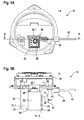
- FIG. 1B shows the image acquisition system 10 according to the invention with a camera unit 20 in the closed position la, with the lens 20.1 behind the protective element 21 is inaccessible from the outside. Furthermore, the mechanism 22 can be seen, wherein the deflection element 30 is in this case designed as a deflection roller 30 with a rotation axis 30.1 and is in operative connection with the traction means 41 as a transmission element 40. The traction means 41 of the transmission element 40 is thereby deflected by the deflection roller 30 and is fastened to the connection element 24 of the camera slide 23.
- the deflection element 30 is in this case designed as a deflection roller 30 with a rotation axis 30.1 and is in operative connection with the traction means 41 as a transmission element 40.
- the traction means 41 of the transmission element 40 is thereby deflected by the deflection roller 30 and is fastened to the connection element 24 of the camera slide 23.
- the traction means 41 which is attached at its one end to the connecting element 24, is guided with its other end through the encapsulated cable housing 42, which is supported by the stop sleeve 43 on the imaging system 10.
- the camera carriage 23 has a further stop element 24 on which in FIG. 1B in dashed form, a second deflection roller 31 is shown with a second axis of rotation 31.1.
- the second deflecting roller 31 is arranged such that when the camera carriage 23 moves from the closed position la to the open position IIa via the traction means 41, the protective element 21 is moved from the closed position la into the open position IIa. Accordingly, at a force on the traction means 41 and the deflecting element 30, at the same time when moving the camera carriage 23 in the open position, the protective element 21 by the second pulling means 41 and the second guide roller 31, this moved to the open position IIa.
- the deflection element 30 or the deflection roller 30 has a minimum radius (guide radius measured from the rotation or rotation axis 30.1 until the traction device abuts the deflection element 30 or the deflection roller) of 3 times to 30 times, in particular 5 times 20 times especially, preferably from 8 times to 15 times, the cross-sectional thickness of the transmission element 40, in particular of the traction means 41 (without outer casing 42), in order to enable a low-friction and wear-free power transmission.
- FIG. 1C shows similar to the FIG. 1B the imaging system 10 according to the invention in the closed position la, in which the camera unit 20 is arranged with the lens 20.1 behind the protective element 21.
- the protective element 21 covers the opening area 50 of the lens 20.1, so that the lens 20.1 or the camera unit 20 is protected against environmental influences.
- the mechanism 22 with the deflection rollers 30 and a second deflection roller 31 with the corresponding axes 30.1 and 31.1 can be seen.
- Analogous to FIG. 1B will also be in the Figure 1C moved by a force on the transmission element 40, both the camera unit 20 and the protective element 21 from a closed position to an open position.
- the FIG. 2A shows the image acquisition system 10 in the maintenance position IIIa, which does not correspond to the open position IIa or the closed position la.
- the maintenance position IIIa allows easier access to the camera unit 20 or the lens 20.1, so that in case of maintenance, repairs or cleaning are facilitated.
- the camera carriage 23 is located away from the opening area 50.
- the camera unit 20 can be manually moved out of the camera carriage 23 so that the camera unit 20 is moved out of the camera carriage 23 for maintenance or repair work can be without the camera carriage 23 has to be moved completely into the open position la.
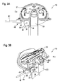
- FIG. 2B shows the image acquisition system 10 in the maintenance position IIIa, wherein it can be seen that the camera unit 20 is moved to a large extent from the camera carriage 23, wherein the camera carriage 23 is in its closed position. Consequently, a good access to the camera unit 20 or the lens 20.1 is given, so that the camera unit 20 replaced or z. B. the lens 20.1 can be cleaned.
- the integrally formed protective element 21 is pivoted about an axis of rotation in the open position, wherein the part of the protective element 21, which itself is located above the pivot axis, pivoted into a housing of the image acquisition system system 10, so that at the same time located below the pivot axis part of the protective element 21 is pivoted out of the housing of the imaging system 10 addition.
- the transmission means 40 which is designed here as a flexible traction system 40, has an encapsulated cable housing 42, a flexible tension element 41 and a stop sleeve 43.
- the stop sleeve 43 is also here in a receptacle on a housing on the stop sleeve 43 also largely encapsulated by environmental influences.
- FIG. 3A shows the image acquisition system 10 in the open position IIa, in which the circular protective element 21, the camera unit 20 and the lens 20.1 for image capture releases.
- the camera carriage 23 is in an open position IIa, in which the camera carriage 23 has moved out of its receptacle and the camera unit 20 or the lens 20.1 likewise projects out of the camera carriage 23 and thus out of the imaging system 10.
- the connection element 24 of the camera slide 23 in the vicinity of the deflection element 30, whereby it can be seen that the camera slide is in an open position, and the traction means 41 from a drive 60 so with a tensile force is acted upon that a majority of the traction means 41 is located outside of the imaging system 10.
- FIG. 3B shows the image capture system 10 in the open position IIa, it can be seen how the protective element 21 is pivoted into the open position and the camera unit 20 and lens 20.1 is released for image capture of an outdoor area. It can also be seen how the camera unit 20 is pivoted out of the camera carriage 23 about a pivot point, resulting in a suitable image capture area.
- the drive 60 with a motor 61 shown schematically. From the drive 60, the flexible traction means 40 goes to the deflection element 30 in order, inter alia, to actuate the mechanism 22. In order to change the torque from the motor 61, a self-locking may possibly be provided by a gear in the drive 60.
Landscapes
- Engineering & Computer Science (AREA)
- Multimedia (AREA)
- Signal Processing (AREA)
- Mechanical Engineering (AREA)
- Human Computer Interaction (AREA)
- Studio Devices (AREA)
Abstract
sich in der Schließstellung (Ia) des Schutzelementes (21) zumindest eine Linse (20.1) der Kameraeinheit (20) von außen unzugänglich hinter dem Schutzelement (21) befindet, und in der Offenstellung (IIa) zumindest die Linse (20.1) der Kameraeinheit (20) durch das Schutzelement (21) zur Bilderfassung freigegeben ist.
Description
- Die vorliegende Erfindung betrifft ein Bilderfassungssystem mit einer Kameraeinheit, zur Bilderfassung des Außenbereiches eines Kraftfahrzeuges gemäß dem Oberbegriff von Anspruch 1. Das Bilderfassungssystem ist dabei versehen mit einer Kameraeinheit, die zur Bilderfassung des Außenbereiches eines Kraftfahrzeuges dient, und einem Schutzelement, wobei zumindest die Kameraeinheit und/oder das Schutzelement über einen Mechanismus mittels eines Antriebs von zumindest einer Schließstellung in zumindest eine Offenstellung bewegbar sind, wobei sich in der Schließstellung des Schutzelementes zumindest eine Linse der Kameraeinheit von außen unzugänglich hinter dem Schutzelement befindet, und in der Offenstellung zumindest die Linse der Kameraeinheit durch das Schutzelement zur Bilderfassung freigegeben ist.
- Es ist bekannt, dass Bilderfassungssysteme aus dem Stand der Technik mit einer Kameraeinheit ausgestattet sind, die über einen Antrieb von einer Schließstellung in eine Offenstellung und umgekehrt bewegt werden können. Darüber hinaus ist aus der
DE 20 2013 105 314 U1 ein Kraftfahrzeugschloss bekannt, das eine Schlossmechanik aufweist, die mit einem Antrieb und einem flexiblen Zugmittel in die entsprechenden Funktionszustände bringbar ist. - Nachteilhaft bei Bilderfassungssystemen der vorbenannten Art ist, dass das Bilderfassungssystem für den Einbau in ein Fahrzeug genügend Bauraum zur Verfügung stellen muss, damit der Antrieb für die Kameraeinheit derart angeordnet werden kann, dass eine Kraftübertragung von dem Antrieb zur Kameraeinheit über ein starres Übertragungselement hergestellt werden kann. Derartige Systeme sind sehr starr in ihrer Verwendung an einem entsprechenden Fahrzeug. Eine Anpassbarkeit an unterschiedliche Fahrzeug- und Einbausituationen ist somit nicht möglich.
- Es ist Aufgabe der vorliegenden Erfindung, die voranstehend beschriebenen Nachteile zumindest teilweise zu beheben. Insbesondere ist es Aufgabe der vorliegenden Erfindung, den Antrieb der Kameraeinheit räumlich flexibel zur Kameraeinheit anzuordnen, so dass der Antrieb innerhalb eines Gehäuses des Bilderfassungssystems oder auch außerhalb angeordnet werden kann.
- Voranstehende Aufgabe wird gelöst durch ein Bilderfassungssystem mit den Merkmalen des Anspruchs 1. Weitere Merkmale und Details der Erfindung ergeben sich aus den Unteransprüchen, der Beschreibung und den Zeichnungen.
- Erfindungsgemäß weist das Bilderfassungssystem mit einer Kameraeinheit zur Bilderfassung des Außenbereichs eines Kraftfahrzeuges zumindest ein Schutzelement auf, wobei zumindest die Kameraeinheit und/oder das Schutzelement über einen Mechanismus mittels eines Antriebs von zumindest einer Schließstellung in zumindest eine Offenstellung bewegbar ist, wobei sich in der Schließstellung das Schutzelement zumindest eine Linse der Kameraeinheit von außen unzugänglich hinter dem Schutzelement befindet und in der Offenstellung zumindest die Linse der Kameraeinheit durch das Schutzelement zur Bilderfassung freigegeben ist. Weiter ist zumindest ein Umlenkelement an dem Mechanismus angeordnet, das zur Richtungsänderung der an dem Mechanismus anliegenden Kraft dient, wodurch ein kompakter Bauraum realisiert ist. Dadurch ergibt sich der Vorteil, dass der Antrieb räumlich flexibel zur Kameraeinheit angeordnet werden kann. Diesbezüglich ist es vorstellbar, dass der Antrieb innerhalb des Gehäuses der Kameraeinheit oder auch außerhalb eines Gehäuses der Kameraeinheit und damit an einem beliebigen Ort am Fahrzeug angeordnet werden kann. Realisiert wird dies durch die mechanische Verbindung zwischen dem Antrieb und der Kameraeinheit, die über das Umlenkelement die zu übertragende Kraft auch bei einer Richtungsänderung überträgt. Aufgrund des gemeinsamen Mechanismus für die Kameraeinheit und das Schutzelement, muss das Schutzelement nicht durch die Kamera selbst aufgestoßen werden, wodurch mechanische Belastungen an den beteiligten Bauteilen vermindert werden. Es ist darüber hinaus auch denkbar, dass das Schutzelement derart gelagert ist, dass dieses unabhängig von der Kameraeinheit geöffnet bzw. geschlossen werden kann ohne dass die Kamera in die Schließ- bzw. Offenstellung gebracht wird. Dadurch wird ermöglicht, dass die zumindest eine Linse der Kameraeinheit von außen einfach zugänglich ist. Das Schutzelement kann über eine translatorische und/oder eine rotatorische Bewegung von der Offenstellung in die Schließstellung und umgekehrt bewegt werden. Zu diesem Zweck kann das Schutzelement durch eine Rückstellfeder beaufschlagt sein, um das Schutzelement selbständig in die Schließstellung zu überführen.
- Ein entscheidender Kerngedanke der vorliegenden Erfindung ist die flexible räumliche Anordnung des Antriebs für die Kameraeinheit innerhalb des Fahrzeugs, wodurch die Variabilität bei der Bauraumgestaltung sowie der benötigte Bauraum optimiert wird, da die Kraftübertragung durch das Umlenkelement in seiner Richtung verändert werden kann, so dass der Antrieb deutlich beabstandet bzw. an einer schwer zugänglichen Stelle (am Fahrzeug) angeordnet werden kann. Die realisierte Richtungsänderung der anliegenden Kraft ermöglicht es den Antrieb auch winkelversetzt zur Kameraeinheit anzuordnen.
- Ein besonderer Vorteil ergibt sich dadurch, dass das Umlenkelement eine Umlenkrolle ist, insbesondere dass die Umlenkrolle beweglich gelagert und um eine Rotationsachse drehbar ist. Eine erfindungsgemäße Umlenkrolle kann dabei eine voll- oder teilkreisförmige Rolle sein, die sowohl starr als auch beweglich um eine Rotationsachse gelagert ist. Eine zumindest teilkreisförmige Umlenkrolle oder vollständige Umlenkrolle ermöglicht eine reibungsarme und somit eine verschleissarme Kraftübertragung, wobei insbesondere bei einer drehbar gelagerten Umlenkrolle die Kraftverluste infolge von Reibung deutlich verringert werden. Die Umlenkrolle kann dabei als ein Vollzylinder- oder ein Hohlzylinder mit einer Verbindung des Zylindermantels mit der Drehachse bzw. des Lagers sein. Darüber hinaus kann ein Hohlzylinder auch Verstärkungsrippen aufweisen, die auftretende mechanische Belastungen aufnehmen können. Auch ist es denkbar, dass die Umlenkrolle zumindest einen Steg an ihrer Randfläche aufweist, so dass sich entlang der Lauffläche eine Steigung ergibt. Vorteilhafterweise besitzt die Umlenkrolle einen zweiten Steg entlang der Lauffläche, so dass zwischen den beiden Stegen eine gekrümmte U-förmige Lauffläche entsteht.
- Ein wesentliches Merkmal einer erfindungsgemäßen Umlenkrolle ist dadurch charakterisiert, dass diese als eine Art Kraftwandler dient, die möglichst reibungsarm auf einer Achse gelagert ist und eine Richtungsänderung des Kraftvektors, ohne Änderung des Kraftbetrages bewirkt.
- Ebenfalls ist es denkbar, dass das Umlenkelement bzw. die Umlenkrolle exzentrisch zur ihrer Drehachse gelagert ist, wodurch sich das Kraftverhältnis zum Verstellen weiter beeinflussen lässt.
- Im Rahmen der Erfindung ist es denkbar, dass die Kameraeinheit über einen Kameraschlitten zwischen der Offenstellung und der Schließstellung stufenlos bewegbar ist. Dies hat zum Vorteil, dass im eingebauten Zustand das Bilderfassungssystem bündig mit der Fahrzeugkarosserie abschließen kann, ohne dass die Kamera aus dem Bilderfassungssystem herausragt. Daraus ergibt sich außerdem ein deutlich erhöhter Schutz vor Umwelteinflüssen, Vandalismus und Diebstahl, da die Kameraeinheit in einem Teil der Fahrzeugkarosserie versenkt werden kann. Die Bewegung der Kameraeinheit über einen erfindungsgemäßen Kameraschlitten ermöglicht einen Stellungswechsel der Kameraeinheit von einer Ruhestellung in eine Bilderfassungsstellung, bei der die zumindest eine Linse zur Bilderfassung des Außenbereiches des Kraftfahrzeuges freigegeben ist. Vorteilhafterweise kann die Kamera am Kameraschlitten über mindestens ein Gelenk oder Gelenkmechanismus bzw. Führungsmechanismus verbunden werden, so dass neben einer horizontalen Bewegung auch eine vertikale oder kombinierte Bewegung der Kameraeinheit ermöglicht ist.
- Des Weiteren ist es denkbar, dass zumindest ein Übertragungselement mit seinem einen Ende an dem Kameraschlitten und/oder dem Schutzelement angeordnet ist, insbesondere das Übertragungselement mit seinem einen Ende an dem Kameraschlitten und/oder dem Schutzelement, insbesondere an einem Anschlusselement des Kameraschlittens und/oder des Schutzelementes, befestigt ist. Das Übertragungsmittel dient der flexiblen Kraftübertragung des Antriebs über das Umlenkelement auf den Kameraschlitten bzw. das Schutzelement, so dass der Kameraschlitten und/oder das Schutzelement von einer Schließstellung in zumindest eine Offenstellung bzw. von einer Ruhestellung in eine Aufzeichnungsstellung bewegt werden kann. Dementsprechend ist das eine Ende des Übertragungselementes an dem Antrieb befestigt und das andere Ende des Übertragungselementes an dem Kameraschlitten und/oder dem Schutzelement. Besonders bevorzugt ist dabei die Befestigung des Übertragungselementes mit seinem einen Ende an einem Anschlusselement des Kameraschlittens und/oder des Schutzelementes, wobei das Anschlusselement einteilig mit dem Kameraschlitten bzw. dem Schutzelement ausgebildet sein kann. Die Verbindung des Anschlusselementes zum Kameraschlitten bzw. zum Schutzelement kann hierbei durch eine Hakenverbindung, eine Klebeverbindung, eine Schraubverbindung, eine Klemmverbindung oder durch Vergießen hergestellt sein. Eine Hakenverbindung sowie eine Schraubverbindung und eine Klemmverbindung haben dabei den Vorteil, dass diese reversibel und somit austauschbar im Falle eines Defektes sind. Das Vergießen des Übertragungselementes sowie ein Verkleben stellt eine dauerhafte und vor Umwelteinflüssen geschützte Verbindungstechnik dar. Darüber hinaus werden bei derartigen Verbindungen keine weiteren Bauteile benötigt, die weitere Kosten verursachen und verschleißen können.
- Vorteilhafterweise ist das Übertragungselement flexibel ausgebildet, insbesondere ein flexibles Zugmittel. Unter einem flexiblen Übertragungselement kann dabei ein Seil, ein Draht, eine Kette, ein Riemen, ein Band oder eine Gelenkstange verstanden werden. Besonders vorteilhaft ist es jedoch, wenn das Übertragungselement ein flexibles Zugmittel ist, das flexibel und bauraumtechnisch günstig angeordnet werden kann. Hierbei kann es sich bspw. um einen Bowdenzug handeln, der neben einer nahezu verlustfreien Kraftübertragung auch besonders verschleißfest ist. Ein solcher Bowdenzug besteht üblicherweise aus einem Metalldraht oder einem Drahtseil, so dass Kräfte auch entlang von Biegungen übertragen werden können.
- Erfindungsgemäß ist es denkbar, dass das Zugsystem ein gedichtetes Zugsystem ist, insbesondere mindestens eine gekapselte Zughülle, mindestens ein flexibles Zugmittel, insbesondere mit einer gleitfähigen Beschichtung, wie z. B. einer PTFE- (PTFE-Polytetrafluorethen) oder einer Graphit-Beschichtung , mindestens eine Anschlagshülse sowie mindestens einen Liner, indem ein flexibles Zugmittel anordbar ist, aufweist. Die Zughülle wirkt dabei als mechanische Führung für das flexible Zugmittel und als Gegenlager für die übertragenen Zugkräfte, so dass das flexible Zugmittel Kräfte auch entlang von Biegungen übertragen kann. Die gleitfähige Beschichtung des flexiblen Zugmittels verringert die Reibung des Zugmittels bei einer Bewegung innerhalb der Zughülle bzw. innerhalb des Liners und bewirkt somit eine hohe Haltbarkeit und einen Schutz vor Umwelteinflüssen, insbesondere Schmutz und Feuchtigkeit. Des Weiteren besteht durch eine Beschichtung sowie eine gekapselte Zughülle ein Vorteil gegenüber herkömmlichen galvanisierten sowie Stainless-Steel-Zügen aufgrund der geringeren Reibung und dem zusätzlichen Schutz vor Feuchtigkeit. Das Zugsystem ist dabei derart ausgestaltet, dass zumindest die gekapselte Zughülle mit einer Anschlagshülse von dem Antrieb bis zu einem Gehäuse des Bilderfassungssystems ragt, so dass innerhalb des Gehäuses des Bilderfassungssystems lediglich das flexible Zugmittel mit einer gleitfähigen Beschichtung entlang des Umlenkelementes verläuft. Somit wird eine größtmögliche Flexibilität des Zugmittels innerhalb des Gehäuses des Bilderfassungssystems gewährleistet, so dass je nach Biegeradius entlang des Umlenkelementes die Zugkraft optimal übertragen werden kann.
- Idealerweise weist das Umlenkelement oder die Umlenkrolle einen Minimalradius (Führungsradius gemessen von der Dreh- bzw. Rotationsachse bis zur Anlage des Zugmittels an das Umlenkelement oder die Umlenkrolle) vom 3-fachen bis 30-fachen, insbesondere vom 5-fachen bis 20-fachen, besonders bevorzugt vom 8-fachen bis 15-fachen, der Querschnittsdicke des Übertragungselementes, insbesondere des Zugmittels (ohne Zughülle), auf, um eine reibungsarme und verschleißfreie Kraftübertragung zu ermöglichen.
- Des Weiteren ist es denkbar, dass die Kameraeinheit, insbesondere der Kameraschlitten, in eine Wartungsstellung bringbar ist, die nicht der Offenstellung und/oder der Schließstellung entspricht. Eine Wartungsstellung ermöglicht dabei einen erleichterten Zugriff der Kameraeinheit, so dass im Reparatur- oder Reinigungsfall lediglich die Kameraeinheit zugänglich gemacht wird ohne das komplette Bilderfassungssystem aus dem Fahrzeug ausbauen zu müssen. Dementsprechend ist es auch denkbar, dass die Kameraeinheit bei einem Defekt einfach ausgetauscht werden kann oder von außen Schmutz oder andere Fremdkörper von der Kameraeinheit bzw. der zumindest einen Kameralinse befreit werden kann.
- Vorteilhaft ist es ebenfalls, wenn das Schutzelement einteilig oder mehrteilig als Verschluss für einen Öffnungsbereich des Bilderfassungssystems, insbesondere des Kameraschlittens, ausgestaltet ist, wobei das Schutzelement insbesondere als ein Lamellen- oder Zentralverschluss oder Rolladenverschluss oder Blendenverschluss gestaltbar ist. Ein einteiliges Schutzelement hat dabei den Vorteil, dass dies kostengünstig und einfach herstellbar ist, wobei es sich um ein Spritzgussteil aus Kunststoff oder ein Metallteil handeln kann. Ein mehrteiliges Schutzelement bietet dem gegenüber den Vorteil dieses flexibler zu gestalten, so dass mehrere Teile gelenkig untereinander verbunden sind, so dass diese bewegbar z. B. entlang einer Biegung oder Kante aufrollbar sind. Dementsprechend können die Teile des Schutzelementes innerhalb des Gehäuses bzw. der Fahrzeugkarosserie in der Offenstellung angeordnet werden.
- Ein erfindungsgemäßes Bilderfassungssystem lässt sich dahingehend weiterbilden, dass eine Reinigungsanlage an dem Bilderfassungssystem anordbar ist, die über das Übertragungselement bewegbar ist. Dabei ermöglicht die Reinigungsanlage die Kamera bzw. die Kameralinse von Schmutz und anderen Fremdkörpern zu befreien, so dass eine freie Sicht zur Bilderfassung des Außenbereichs ermöglicht wird. Dies erhöht die Funktionssicherheit des Bilderfassungssystems und ermöglicht den Einsatz auch bei schlechten Wetterbedingungen. Hierbei ist es auch denkbar, dass über die Reinigungsanlage Mittel zur Pflege bzw. frostunempfindliche Mittel zur Reinigung der Kameraeinheit eingesetzt werden. Auch der Einsatz von Antibeschlagsmitteln für die Kameralinse ist hierbei denkbar.
- Erfindungsgemäß ist es darüber hinaus denkbar, dass der Mechanismus mit dem Umlenkelement sowohl zur Bewegung des Schutzelementes, des Kameraschlittens und der Reinigungsanlage dient. Hierzu kann der Mechanismus mit einer Mehrzahl an Übertragungs- und Umlenkelementen ausgestattet werden, so dass bei kompakter Bauweise die Bewegung des Schutzelementes, des Kameraschlittens und der Reinigungsanlage realisiert werden kann.
- Im Rahmen der Erfindung kann die Offenstellung und/oder die Schließstellung und/oder die Wartungsstellung durch einen Endlagenschalter und/oder einen mechanischen Anschlag feststellbar sein. Somit kann ein Defekt der Kameraeinheit, insbesondere der Anschlüsse und Kabel sowie des Antriebes verhindert werden. Dabei wird verhindert, dass die Anschlüsse und Kabel innerhalb des Bilderfassungssystems nicht eingeklemmt werden, so dass Brüche und/oder Risse weitestgehend verhindert werden. Darüber hinaus kann der Antrieb bei Erreichen des Endlagenschalters und/oder des mechanischen Anschlags ausgeschaltet werden, so dass unnötige Belastungen, die zum Defekt des Antriebs führen können, verhindert werden. Weiterhin kann über einen erfindungsgemäßen Endlagenschalter ein Signal übertragen werden, wodurch die Position der Kameraeinheit festgestellt werden kann und an ein entsprechendes Anzeigemittel übertragen werden, wo das Signal ausgewertet und damit die Position angezeigt wird.
- Des Weiteren ist es denkbar, dass an der Kameraeinheit und/oder dem Kameraschlitten und/oder dem Schutzelement und/oder der Reinigungsanlage ein zweites Übertragungselement anordbar ist, wodurch eine Antriebskraft in eine zweite Bewegungsrichtung übertragbar ist. Hierdurch kann realisiert werden, dass durch einen weiteren Antrieb oder den bisher bekannten Antrieb für beide Bewegungsrichtungen, d. h. von der Ruhestellung in die Aufzeichnungsstellung bzw. von der Offenstellung in die Schließstellung bzw. eine Wartungsstellung auch in die Umkehrrichtung bewegt werden kann.
- Im Rahmen der Erfindung kann die Kameraeinheit und/oder der Kameraschlitten und/oder das Schutzelement und/oder die Reinigungsanlage federbelastet sein. Dadurch wird ermöglicht, dass bei einer Zugvorrichtung, die eine Kraftübertragung lediglich in eine Richtung ermöglicht, die Umkehrrichtung der Bewegung durch eine federbelastete Befestigung hergestellt werden kann. Dies erspart einen weiteren Antrieb, der die jeweilige Umkehrrichtung umsetzen müsste. Dadurch kann der Bauraum weiter komprimiert werden, wobei gleichzeitig die Ausfallsicherheit erhöht wird, da es sich um eine rein mechanische Verbindung handelt, die nicht von einem weiteren Antrieb abhängig ist. Darüber hinaus handelt es sich hierbei um eine kostengünstige Ausführungsform.
- Es ist des Weiteren denkbar, dass die Kameraeinheit und/oder der Kameraschlitten und/oder das Schutzelement und/oder die Reinigungsanlage durch einen Energiespeicher in die Offenstellung und/oder die Schließstellung und/oder die Wartungsstellung bringbar ist. Erfindungsgemäß ist es insbesondere denkbar, dass es sich um einen Energiespeicher handelt, der die kinetische Energie temporär speichert und im Bedarfsfall für eine entsprechende Bewegung wieder zur Nutzung freigibt. Auch hierdurch kann ein weiterer Antrieb für die Übertragung der Kraft entgegen der Zugrichtung, eingespart werden, so dass hierdurch der Bauraum und die Herstellungskosten weiter reduziert werden können.
- Vorteilhaft kann der Antrieb eine Selbsthemmung aufweisen, so dass der Antrieb nicht bestromt werden muss, um eine stationäre Stellung zu halten. Dies ermöglicht zum einen die benötigte Energie für den Antrieb zu minimieren und dass durch einfache mechanische Konstruktion eine gewünschte Position gehalten werden kann. Dabei kann die Selbsthemmung z. B. durch einen entsprechenden Neigungswinkel, eine entsprechende Oberflächenrauigkeit der Auflagenfläche, die Werkstoffpaarung, die Gleitgeschwindigkeit, durch einen geeigneten Schmierstoff und durch Erwärmung beeinflusst werden. Bevorzugt kann es sich dabei um Getriebe handeln, wobei der Effekt durch eine hohe Übersetzung und Trägheitsmomente bzw. kleine Wirkungsgrade erreicht wird. Vorzugweise handelt es sich dabei um Schneckengetriebe, die die benötigten Anforderungen erfüllen, wenn der Steigungswinkel kleiner ist als der wirksame Winkel des Reibkegels.
- Weitere, die Erfindung verbessernde Maßnahmen ergeben sich aus der nachfolgenden Beschreibung zu einigen Ausführungsbeispielen der Erfindung, welche in den Figuren schematisch dargestellt sind. Sämtliche aus den Ansprüchen, der Beschreibung oder den Zeichnungen hervorgehende Merkmale und/oder Vorteile, einschließlich konstruktiver Einzelheiten, räumliche Anordnungen und Verfahrensschritten, können sowohl für sich als auch in den verschiedensten Kombinationen erfindungswesentlich sein. Es zeigen jeweils schematisch:
- Fig.1A
- das Bilderfassungssystem in einer Frontansicht,
- Fig.1B
- das Bilderfassungssystem in der Schließstellung la,
- Fig.1C
- das Bilderfassungssystem in der Schließstellung la
- Fig.2A
- das Bilderfassungssystem in der Wartungsstellung IIIa,
- Fig.2B
- das Bilderfassungssystem in der Wartungsstellung IIIa,
- Fig.3A
- das Bilderfassungssystem in der Offenstellung IIa,
- Fig.3B
- das Bilderfassungssystem in der Offenstellung IIa,
- Elemente mit gleicher Funktion und Wirkungsweise sind in den
Fig. 1A bis 3B jeweils mit denselben Bezugszeichen versehen. - Die
Figur 1 zeigt ein erfindungsgemäßes Bilderfassungssystem in der Offenstellung IIa, mit einer Kameraeinheit 20, welche eine Linse 20.1 aufweist. Die Kameraeinheit 20 ist hierbei derart in einem Kameraschlitten 23 angeordnet, dass die Linse 20.1 durch den Öffnungsbereich 50 einen Außenbereich eines Kraftfahrzeuges erfassen kann. Darüber hinaus ist das Umlenkelement 30 des Mechanismus 22 zu erkennen, welcher in Wirkverbindung mit dem Kameraschlitten 23 steht, sodass dieser zur Richtungsänderung einer an dem Umlenkelement 30 bzw. dem Mechanismus 22 anliegende Kraft von einem Antrieb 60 (s.Fig. 3B ) dazu dient, die Kameraeinheit 20 bzw. den Kameraschlitten 23 zu bewegen. DieFigur 1 zeigt hierbei das Bilderfassungssystem 10 (ohne Antrieb 60) in einer Frontansicht. - Die
Figur 1B zeigt das erfindungsgemäße Bilderfassungssystem 10 mit einer Kameraeinheit 20 in der Schließstellung la, wobei sich die Linse 20.1 hinter dem Schutzelement 21 von außen unzugänglich befindet. Weiterhin ist der Mechanismus 22 zu erkennen, wobei das Umlenkelement 30 hierbei als eine Umlenkrolle 30 mit einer Rotationsachse 30.1 ausgebildet ist und in Wirkverbindung mit dem Zugmittel 41 als Übertragungselement 40 steht. Das Zugmittel 41 des Übertragungselementes 40 wird dabei durch die Umlenkrolle 30 umgelenkt und ist an dem Anschlusselement 24 des Kameraschlittens 23 befestigt. Das Zugmittel 41, welches an seinem einen Ende an dem Anschlusselement 24 befestigt ist, wird mit seinen anderen Ende durch die gekapselte Zughülle 42 geführt, welche durch die Anschlagshülse 43 an dem Bilderfassungssystem 10 abgestützt ist. Darüber hinaus weist der Kameraschlitten 23 ein weiteres Anschlagselement 24 auf, an dem inFigur 1B in gestrichelter Form eine zweite Umlenkrolle 31 mit einer zweiten Rotationsachse 31.1 gezeigt ist. Die zweite Umlenkrolle 31 ist dabei derart angeordnet, dass sich bei einer Bewegung des Kameraschlittens 23 von der Schließstellung la in die Offenstellung IIa über das Zugmittel 41 das Schutzelement 21 von der Schließstellung la in die Offenstellung IIa bewegt wird. Dementsprechend kann bei einer Krafteinleitung über das Zugmittel 41 bzw. das Umlenkelement 30, gleichzeitig bei Verschieben des Kameraschlittens 23 in die Offenstellung, das Schutzelement 21 durch das zweite Zugmittel 41 und über die zweite Umlenkrolle 31, dieses in die Offenstellung IIa bewegt werden. - Hierbei weist das Umlenkelement 30 oder die Umlenkrolle 30 einen Minimalradius (Führungsradius gemessen von der Dreh- bzw. Rotationsachse 30.1 bis zur Anlage des Zugmittels an das Umlenkelement 30 oder die Umlenkrolle) vom 3-fachen bis 30-fachen, insbesondere vom 5-fachen bis 20-fachen besonders, bevorzugt vom 8-fachen bis 15-fachen, der Querschnittsdicke des Übertragungselementes 40, insbesondere des Zugmittels 41 (ohne Zughülle 42), auf, um eine reibungsarme und verschleißfreie Kraftübertragung zu ermöglichen.
- Die
Figur 1C zeigt ähnlich wie dieFigur 1B das erfindungsgemäße Bilderfassungssystem 10 in der Schließstellung la, bei der die Kameraeinheit 20 mit der Linse 20.1 hinter dem Schutzelement 21 angeordnet ist. InFigur 1C ist zu erkennen, wie das Schutzelement 21 den Öffnungsbereich 50 der Linse 20.1 abdeckt, sodass die Linse 20.1 bzw. die Kameraeinheit 20 vor Umwelteinflüssen geschützt ist. Darüber hinaus ist der Mechanismus 22 mit den Umlenkrollen 30 sowie eine zweite Umlenkrolle 31 mit den entsprechenden Achsen 30.1 und einen 31.1 zu erkennen. Analog zuFigur 1B wird auch in derFigur 1C durch eine Krafteinleitung über das Übertragungselement 40, sowohl die Kameraeinheit 20 als auch das Schutzelement 21 von einer Schließstellung in eine Offenstellung bewegt. - Die
Figur 2A zeigt das Bilderfassungssystem 10 in der Wartungsstellung IIIa, die nicht der Offenstellung IIa oder der Schließstellung la entspricht. Die Wartungsstellung IIIa ermöglicht einen erleichterten Zugriff auf die Kameraeinheit 20 bzw. die Linse 20.1, sodass im Wartungsfall, Reparaturen oder Reinigungen erleichtert werden. In der Wartungsstellung IIIa befindet sich der Kameraschlitten 23 entfernt vom Öffnungsbereich 50. In der Wartungsstellung IIIa ist es ebenfalls denkbar, dass die Kameraeinheit 20 manuell aus dem Kameraschlitten 23 bewegt werden kann, sodass für Wartungs- oder Reparaturarbeiten die Kameraeinheit 20 aus dem Kameraschlitten 23 herausgefahren werden kann, ohne dass der Kameraschlitten 23 komplett in die Offenstellung la bewegt werden muss. - Auch die
Figur 2B zeigt das Bilderfassungssystem 10 in der Wartungsstellung IIIa, wobei zu erkennen ist, dass die Kameraeinheit 20 zu einem großen Teil aus dem Kameraschlitten 23 herausbewegt ist, wobei sich der Kameraschlitten 23 in seiner Schließstellung befindet. Folglich ist ein guter Zugriff auf die Kameraeinheit 20 bzw. die Linse 20.1 gegeben, sodass die Kameraeinheit 20 ausgetauscht oder z. B. die Linse 20.1 gereinigt werden kann. In derFigur 2B ist das einteilig ausgebildete Schutzelement 21 um eine Rotationsachse in die Offenstellung verschwenkt, wobei sich der Teil des Schutzelementes 21, welcher sich oberhalb der Schwenkachse befindet, in ein Gehäuse des Bilderfassungssystem System 10 hineinschwenkt, sodass gleichzeitig der unterhalb der Schwenkachse gelegene Teil des Schutzelementes 21 aus dem Gehäuse des Bilderfassungssystem 10 hinaus geschwenkt wird. Das Übertragungsmittel 40, welches hier als ein flexibles Zugsystem 40 ausgebildet ist, weist eine gekapselte Zughülle 42, ein flexibles Zugelement 41 sowie eine Anschlagshülse 43 auf. Die Anschlagshülse 43 ist hierbei in einer Aufnahme an einem Gehäuse an der Anschlagshülse 43 ebenfalls weitestgehend abgekapselt von Umwelteinflüssen angeordnet. Durch die gekapselte Zughülle 42 und die Anschlagshülse 43 verläuft das flexible Zugmittel 41, welches durch die gekapselte Zughülle 42 vor Umwelteinflüssen geschützt wird, und erst innerhalb eines Gehäuses des Bilderfassungssystems aus der Zughülle 42 herausgeführt wird. - Die
Figur 3A zeigt das Bilderfassungssystem 10 in der Offenstellung IIa, in der das kreisförmige Schutzelement 21 die Kameraeinheit 20 bzw. die Linse 20.1 zur Bilderfassung freigibt. Der Kameraschlitten 23 befindet sich dabei in einer Offenstellung IIa, in der der Kameraschlitten 23 aus seiner Aufnahme herausgefahren ist und die Kameraeinheit 20 bzw. die Linse 20.1 ebenfalls aus dem Kameraschlitten 23 und somit aus dem Bilderfassungssystem 10 herausragt. Wie an dem Mechanismus 22 zu erkennen ist, befindet sich nun das Anschlusselement 24 des Kameraschlittens 23 in der Nähe des Umlenkelementes 30, wodurch ersichtlich ist, dass der Kameraschlitten sich in einer Offenstellung befindet, und das Zugmittel 41 von einem Antrieb 60 derart mit einer Zugkraft beaufschlagt ist, dass ein Großteil des Zugmittels 41 sich außerhalb des Bilderfassungssystems 10 befindet. - Auch die
Figur 3B zeigt das Bilderfassungssystem 10 in der Offenstellung IIa, wobei zu erkennen ist, wie das Schutzelement 21 in die Offenstellung verschwenkt ist und die Kameraeinheit 20 bzw. Linse 20.1 zur Bilderfassung eines Außenbereiches freigegeben ist. Ebenfalls zu erkennen ist wie die Kameraeinheit 20 um einen Drehpunkt aus dem Kameraschlitten 23 herausgeschwenkt ist, wodurch sich ein geeigneter Bilderfassungsbereich ergibt. - Zusätzlich ist in
Figur 3B auch der Antrieb 60 mit einem Motor 61 schematisch dargestellt. Vom Antrieb 60 geht das flexible Zugmittel 40 zum Umlenkelement 30, um u. a. den Mechanismus 22 zu betätigen. Um das Drehmoment vom Motor 61 zu verändern, kann eine Selbsthemmung ggf. durch ein Getriebe im Antrieb 60 vorgesehen sein. -
- 10
- Bilderfassungssystem
- 20
- Kameraeinheit
- 21
- Schutzelement
- 22
- Mechanismus
- 23
- Kameraschlitten
- 30
- Umlenkelement
- 30.1
- Rotationsachse
- 31
- Umlenkelement
- 31.1
- Rotationsachse
- 40
- Übertragungselement
- 41
- Zugmittel
- 42
- Zughülle
- 43
- Anschlagshülse
- 50
- Öffnungsbereich
- 60
- Antrieb
- 61
- Motor mit ggf. Selbsthemmung
- Ia
- Schließstellung
- IIa
- Offenstellung
- IIIa
- Wartungsstellung
Claims (15)
- Bilderfassungssystem (10) mit einer Kameraeinheit (20), die zur Bilderfassung des Außenbereiches eines Kraftfahrzeuges dient, und
einem Schutzelement (21), wobei zumindest die Kameraeinheit (20) und/oder das Schutzelement (21) über einen Mechanismus (22) mittels eines Antriebs (60) von zumindest einer Schließstellung (la) in zumindest eine Offenstellung (IIa) bewegbar sind, wobei
sich in der Schließstellung (la) des Schutzelementes (21) zumindest eine Linse (20.1) der Kameraeinheit (20) von außen unzugänglich hinter dem Schutzelement (21) befindet, und
in der Offenstellung (IIa) zumindest die Linse (20.1) der Kameraeinheit (20) durch das Schutzelement (21) zur Bilderfassung freigegeben ist,
dadurch gekennzeichnet,
dass zumindest ein Umlenkelement (30, 31) an dem Mechanismus (22) angeordnet ist, das zur Richtungsänderung einer an dem Mechanismus (22) anliegenden Kraft dient, wodurch ein kompakter Bauraum realisiert ist. - Bilderfassungssystem (10) nach Anspruch 1,
dadurch gekennzeichnet,
dass das Umlenkelement (30, 31) eine Umlenkrolle (30, 31) ist, insbesondere dass die Umlenkrolle (30, 31) beweglich gelagert ist, und insbesondere um eine Rotationsachse (30.1, 31.1) drehbar ist. - Bilderfassungssystem (10) nach Anspruch 1 oder 2,
dadurch gekennzeichnet,
dass die Kameraeinheit (20) über einen Kameraschlitten (23) zwischen der Offenstellung (IIa) und der Schließstellung (la) stufenlos bewegbar ist. - Bilderfassungssystem (10) nach Anspruch einem der vorhergehenden Ansprüche,
dadurch gekennzeichnet,
dass zumindest ein Übertragungselement (40) mit seinem einen Ende an dem Kameraschlitten (22) und/oder dem Schutzelement (21) angeordnet ist, insbesondere an einem Anschlusselement (24) des Kameraschlittens (23) und/oder des Schutzelementes (21), befestigt ist
und/oder dass ein Übertragungselement (40) flexibel ausgebildet, insbesondere ein flexibles Zugsystem (41), ist. - Bilderfassungssystem (10) nach einem der vorhergehenden Ansprüche,
dadurch gekennzeichnet,
dass das Zugsystem (40) ein gedichtetes Zugsystem (40) ist, insbesondere mindestens eine gekapselte Zughülle (42), mindestens ein flexibles Zugmittel (41), insbesondere mit einer gleitfähigen Beschichtung, mindestens eine Anschlagshülse (43) sowie mindestens einen Liner, in dem das flexible Zugmittel (41) anordbar ist, aufweist. - Bilderfassungssystem (10) nach einem der vorhergehenden Ansprüche,
dadurch gekennzeichnet,
dass die Kameraeinheit (20), insbesondere der Kameraschlitten (23), in eine Wartungsstellung (IIIa) bringbar ist, die nicht der Offenstellung (IIa) und/oder der Schließstellung (la) entspricht. - Bilderfassungssystem (10) nach einem der vorhergehenden Ansprüche,
dadurch gekennzeichnet,
dass das Schutzelement (21) einteilig oder mehrteilig als Verschluss für einen Öffnungsbereich (50) des Bilderfassungssystems (10), insbesondere des Kameraschlittens (23) ausgestaltet ist, wobei das Schutzelement (21) insbesondere als ein Lamellen- oder Zentralverschluss oder Rolladenverschluss oder Blendenverschluss gestaltbar ist. - Bilderfassungssystem (10) nach einem der vorhergehenden Ansprüche,
dadurch gekennzeichnet,
dass eine Reinigungsanlage an dem Bilderfassungssystem (10) anordbar ist, die durch ein Übertragungselement antreibbar ist. - Bilderfassungssystem (10) nach einem der vorhergehenden Ansprüche,
dadurch gekennzeichnet,
dass der Mechanismus (22) sowohl zur Bewegung des Schutzelementes (21), des Kameraschlittens (23) und der Reinigungsanlage dient. - Bilderfassungssystem (10) nach einem der vorhergehenden Ansprüche,
dadurch gekennzeichnet,
dass die Offenstellung (IIa) und/oder die Schließstellung (la) und/oder die Wartungsstellung (IIIa, IIIb) durch einen Endlagenschalter und/oder einen mechanischen Anschlag feststellbar ist. - Bilderfassungssystem (10) nach einem der vorhergehenden Ansprüche,
dadurch gekennzeichnet,
dass an der Kameraeinheit (20) und/oder dem Kameraschlitten (23) und/oder dem Schutzelement (21) und/oder der Reinigungsanlage ein zweites Übertragungselement (31) anordbar ist, wodurch insbesondere eine Kraft in eine zweite Bewegungsrichtung übertragbar ist. - Bilderfassungssystem (10) nach einem der vorhergehenden Ansprüche,
dadurch gekennzeichnet,
dass jeweils ein Umlenkelement (30, 31) für das Schutzelement (21), ein Umlenkelement (30, 31) für den Kameraschlitten (23) und ein Umlenkelement (30, 31) für die Reinigungsanlage vorsehbar ist. - Bilderfassungssystem (10) nach einem der vorhergehenden Ansprüche,
dadurch gekennzeichnet,
dass die Kameraeinheit (20) und/oder der Kameraschlitten (23) und/oder das Schutzelement (21) und/oder die Reinigungsanlage durch Rückstellfedern federbelastet sind. - Bilderfassungssystem (10) nach einem der vorhergehenden Ansprüche,
dadurch gekennzeichnet,
dass die Kameraeinheit (20) und/oder der Kameraschlitten (23) und/oder das Schutzelement (21) und/oder die Reinigungsanlage durch einen Energiespeicher in die Offenstellung (IIa) und/oder die Schließstellung (la) und/oder die Wartungsstellung (IIIa) bringbar ist. - Bilderfassungssystem (10) nach einem der vorhergehenden Ansprüche,
dadurch gekennzeichnet,
dass der Antrieb (60) eine Selbsthemmung aufweisen kann, sodass der Antrieb (60) nicht bestromt werden muss, um eine stationäre Stellung zu halten.
Applications Claiming Priority (1)
| Application Number | Priority Date | Filing Date | Title |
|---|---|---|---|
| DE102015100038.5A DE102015100038A1 (de) | 2015-01-05 | 2015-01-05 | Bilderfassungssystem mit flexiblem Übertragungselement |
Publications (2)
| Publication Number | Publication Date |
|---|---|
| EP3040244A1 true EP3040244A1 (de) | 2016-07-06 |
| EP3040244B1 EP3040244B1 (de) | 2018-07-04 |
Family
ID=55077404
Family Applications (1)
| Application Number | Title | Priority Date | Filing Date |
|---|---|---|---|
| EP16150134.1A Not-in-force EP3040244B1 (de) | 2015-01-05 | 2016-01-05 | Bilderfassungssystem mit flexiblem übertragungselement |
Country Status (3)
| Country | Link |
|---|---|
| US (1) | US9725050B2 (de) |
| EP (1) | EP3040244B1 (de) |
| DE (1) | DE102015100038A1 (de) |
Cited By (2)
| Publication number | Priority date | Publication date | Assignee | Title |
|---|---|---|---|---|
| CN111510606A (zh) * | 2020-04-26 | 2020-08-07 | 深圳市飞龙云商贸有限公司 | 一种防结霜的道路监控设备 |
| EP3919327A1 (de) * | 2020-06-04 | 2021-12-08 | Witte Automotive GmbH | Kameraanordnung |
Families Citing this family (2)
| Publication number | Priority date | Publication date | Assignee | Title |
|---|---|---|---|---|
| CN108234746A (zh) * | 2017-11-29 | 2018-06-29 | 努比亚技术有限公司 | 一种拍摄控制方法、终端及计算机可读存储介质 |
| DE102021003926B4 (de) | 2021-07-30 | 2024-02-08 | Mercedes-Benz Group AG | Kamerahalter und Fahrzeug |
Citations (4)
| Publication number | Priority date | Publication date | Assignee | Title |
|---|---|---|---|---|
| DE19961389A1 (de) * | 1999-12-20 | 2001-06-21 | Mannesmann Vdo Ag | Schutzverschluss für Kameras |
| EP2508393A1 (de) * | 2011-04-05 | 2012-10-10 | Huf Hülsbeck & Fürst GmbH & Co. KG | Vorrichtung mit einer Kameraeinheit |
| DE202013105314U1 (de) | 2013-11-22 | 2014-01-29 | BROSE SCHLIEßSYSTEME GMBH & CO. KG | Kraftfahrzeugschloss |
| DE102013001721A1 (de) * | 2013-02-01 | 2014-08-07 | Brose Fahrzeugteile Gmbh & Co. Kommanditgesellschaft, Hallstadt | Kameraverstelleinheit für ein Fahrzeug |
Family Cites Families (7)
| Publication number | Priority date | Publication date | Assignee | Title |
|---|---|---|---|---|
| US6009189A (en) * | 1996-08-16 | 1999-12-28 | Schaack; David F. | Apparatus and method for making accurate three-dimensional size measurements of inaccessible objects |
| DE102010001196A1 (de) * | 2010-01-15 | 2011-07-21 | Huf Hülsbeck & Fürst GmbH & Co. KG, 42551 | Vereinfachte Vorrichtung einer Kameraeinheit eines Kraftfahrzeugs |
| DE102010013338A1 (de) * | 2010-03-30 | 2011-01-05 | Daimler Ag | Kameraanordnung für ein Fahrzeug |
| DE102010046396A1 (de) * | 2010-09-24 | 2012-03-29 | Huf Hülsbeck & Fürst Gmbh & Co. Kg | Kameraeinheit für ein Kraftfahrzeug |
| DE102011111854A1 (de) * | 2011-08-27 | 2013-02-28 | Volkswagen Aktiengesellschaft | Schwenkmechanismus zum beweglichen Anbringen einer Kamera an einem Fahrzeug |
| KR101302442B1 (ko) * | 2011-10-25 | 2013-09-02 | 김성남 | 무인항공기 카메라 폴딩장치 |
| US8864392B2 (en) * | 2012-02-15 | 2014-10-21 | GM Global Technology Operations LLC | Camera system |
-
2015
- 2015-01-05 DE DE102015100038.5A patent/DE102015100038A1/de not_active Withdrawn
-
2016
- 2016-01-05 EP EP16150134.1A patent/EP3040244B1/de not_active Not-in-force
- 2016-01-05 US US14/988,106 patent/US9725050B2/en not_active Expired - Fee Related
Patent Citations (4)
| Publication number | Priority date | Publication date | Assignee | Title |
|---|---|---|---|---|
| DE19961389A1 (de) * | 1999-12-20 | 2001-06-21 | Mannesmann Vdo Ag | Schutzverschluss für Kameras |
| EP2508393A1 (de) * | 2011-04-05 | 2012-10-10 | Huf Hülsbeck & Fürst GmbH & Co. KG | Vorrichtung mit einer Kameraeinheit |
| DE102013001721A1 (de) * | 2013-02-01 | 2014-08-07 | Brose Fahrzeugteile Gmbh & Co. Kommanditgesellschaft, Hallstadt | Kameraverstelleinheit für ein Fahrzeug |
| DE202013105314U1 (de) | 2013-11-22 | 2014-01-29 | BROSE SCHLIEßSYSTEME GMBH & CO. KG | Kraftfahrzeugschloss |
Cited By (4)
| Publication number | Priority date | Publication date | Assignee | Title |
|---|---|---|---|---|
| CN111510606A (zh) * | 2020-04-26 | 2020-08-07 | 深圳市飞龙云商贸有限公司 | 一种防结霜的道路监控设备 |
| CN111510606B (zh) * | 2020-04-26 | 2021-12-21 | 山东融达智能工程有限公司 | 一种防结霜的道路监控设备 |
| EP3919327A1 (de) * | 2020-06-04 | 2021-12-08 | Witte Automotive GmbH | Kameraanordnung |
| US11818500B2 (en) | 2020-06-04 | 2023-11-14 | Witte Automotive Gmbh | Camera arrangement |
Also Published As
| Publication number | Publication date |
|---|---|
| EP3040244B1 (de) | 2018-07-04 |
| US9725050B2 (en) | 2017-08-08 |
| US20160193972A1 (en) | 2016-07-07 |
| DE102015100038A1 (de) | 2016-07-07 |
Similar Documents
| Publication | Publication Date | Title |
|---|---|---|
| EP2524494B1 (de) | Vereinfachte vorrichtung einer kameraeinheit eines kraftfahrzeugs | |
| EP0937853B1 (de) | Betätigungseinrichtung für eine Schiebetür, insbesondere für Kraftfahrzeuge | |
| EP3040244B1 (de) | Bilderfassungssystem mit flexiblem übertragungselement | |
| EP2113419B1 (de) | Abdeckeinrichtung für den Fahrzeuginnenraum | |
| DE102015214784A1 (de) | Verstellvorrichtung mit einer fremdkraftbetätigt verstellbaren Verschlussklappe | |
| DE202005021669U1 (de) | Vorrichtung zum motor- und kraftbetätigten Bewegen einer um eine Schwenkachse schwenkbaren Klappe eines Fahrzeugs | |
| EP1403555A2 (de) | Betätigungseinrichtung | |
| DE102016212166B4 (de) | Beschattungsvorrichtung für eine Scheibe eines Kraftfahrzeugs | |
| DE20215508U1 (de) | Anhängevorrichtung für Zugfahrzeuge | |
| EP4543642B1 (de) | Energieführungskette mit zugseil-detektoranordnung | |
| EP1564360B1 (de) | Vorrichtung zum motorischen Öffnen und Schliessen eines Karosserieteils | |
| EP3947881B1 (de) | Schiebetürantrieb für ein kraftfahrzeug | |
| DE102020109829A1 (de) | Tankklappen-System eines Kraftfahrzeugs | |
| WO2016202482A1 (de) | Beschattungsvorrichtung für eine scheibe eines kraftfahrzeugs | |
| DE102021003926B4 (de) | Kamerahalter und Fahrzeug | |
| DE202007011084U1 (de) | Festellbremse mit Antriebseinheit und Vorrichtung zur Kraftumsetzung | |
| DE102009002850A1 (de) | Scheibenwischervorrichtung | |
| EP4078638B1 (de) | Not-halt-schalter und maschine mit not-halt-schalter | |
| DE102006043429B4 (de) | Anhängerkupplung | |
| DE102018205781B4 (de) | Antriebseinrichtung | |
| EP3919327B1 (de) | Kameraanordnung | |
| DE102008033478A1 (de) | Abdeckvorrichtung für einen Gepäckraum eines Kraftfahrzeuges | |
| DE102010013171A1 (de) | Kameraanordnung zur Überwachung einer Umgebung eines Fahrzeuges | |
| DE102007003314B4 (de) | Abgaseinrichtung eines Verbrennungsmotors | |
| DE102017106829A1 (de) | Aktor für ziehende Betätigung bei drückend wirkender Antriebseinrichtung |
Legal Events
| Date | Code | Title | Description |
|---|---|---|---|
| PUAI | Public reference made under article 153(3) epc to a published international application that has entered the european phase |
Free format text: ORIGINAL CODE: 0009012 |
|
| AK | Designated contracting states |
Kind code of ref document: A1 Designated state(s): AL AT BE BG CH CY CZ DE DK EE ES FI FR GB GR HR HU IE IS IT LI LT LU LV MC MK MT NL NO PL PT RO RS SE SI SK SM TR |
|
| AX | Request for extension of the european patent |
Extension state: BA ME |
|
| STAA | Information on the status of an ep patent application or granted ep patent |
Free format text: STATUS: REQUEST FOR EXAMINATION WAS MADE |
|
| 17P | Request for examination filed |
Effective date: 20170109 |
|
| RBV | Designated contracting states (corrected) |
Designated state(s): AL AT BE BG CH CY CZ DE DK EE ES FI FR GB GR HR HU IE IS IT LI LT LU LV MC MK MT NL NO PL PT RO RS SE SI SK SM TR |
|
| STAA | Information on the status of an ep patent application or granted ep patent |
Free format text: STATUS: EXAMINATION IS IN PROGRESS |
|
| 17Q | First examination report despatched |
Effective date: 20170629 |
|
| GRAP | Despatch of communication of intention to grant a patent |
Free format text: ORIGINAL CODE: EPIDOSNIGR1 |
|
| STAA | Information on the status of an ep patent application or granted ep patent |
Free format text: STATUS: GRANT OF PATENT IS INTENDED |
|
| INTG | Intention to grant announced |
Effective date: 20180126 |
|
| GRAS | Grant fee paid |
Free format text: ORIGINAL CODE: EPIDOSNIGR3 |
|
| GRAA | (expected) grant |
Free format text: ORIGINAL CODE: 0009210 |
|
| STAA | Information on the status of an ep patent application or granted ep patent |
Free format text: STATUS: THE PATENT HAS BEEN GRANTED |
|
| AK | Designated contracting states |
Kind code of ref document: B1 Designated state(s): AL AT BE BG CH CY CZ DE DK EE ES FI FR GB GR HR HU IE IS IT LI LT LU LV MC MK MT NL NO PL PT RO RS SE SI SK SM TR |
|
| REG | Reference to a national code |
Ref country code: GB Ref legal event code: FG4D Free format text: NOT ENGLISH |
|
| REG | Reference to a national code |
Ref country code: CH Ref legal event code: EP |
|
| REG | Reference to a national code |
Ref country code: AT Ref legal event code: REF Ref document number: 1014158 Country of ref document: AT Kind code of ref document: T Effective date: 20180715 |
|
| REG | Reference to a national code |
Ref country code: IE Ref legal event code: FG4D Free format text: LANGUAGE OF EP DOCUMENT: GERMAN |
|
| REG | Reference to a national code |
Ref country code: DE Ref legal event code: R096 Ref document number: 502016001372 Country of ref document: DE |
|
| REG | Reference to a national code |
Ref country code: NL Ref legal event code: MP Effective date: 20180704 |
|
| REG | Reference to a national code |
Ref country code: LT Ref legal event code: MG4D |
|
| PG25 | Lapsed in a contracting state [announced via postgrant information from national office to epo] |
Ref country code: NL Free format text: LAPSE BECAUSE OF FAILURE TO SUBMIT A TRANSLATION OF THE DESCRIPTION OR TO PAY THE FEE WITHIN THE PRESCRIBED TIME-LIMIT Effective date: 20180704 |
|
| PG25 | Lapsed in a contracting state [announced via postgrant information from national office to epo] |
Ref country code: CZ Free format text: LAPSE BECAUSE OF FAILURE TO SUBMIT A TRANSLATION OF THE DESCRIPTION OR TO PAY THE FEE WITHIN THE PRESCRIBED TIME-LIMIT Effective date: 20180704 Ref country code: NO Free format text: LAPSE BECAUSE OF FAILURE TO SUBMIT A TRANSLATION OF THE DESCRIPTION OR TO PAY THE FEE WITHIN THE PRESCRIBED TIME-LIMIT Effective date: 20181004 Ref country code: GR Free format text: LAPSE BECAUSE OF FAILURE TO SUBMIT A TRANSLATION OF THE DESCRIPTION OR TO PAY THE FEE WITHIN THE PRESCRIBED TIME-LIMIT Effective date: 20181005 Ref country code: FI Free format text: LAPSE BECAUSE OF FAILURE TO SUBMIT A TRANSLATION OF THE DESCRIPTION OR TO PAY THE FEE WITHIN THE PRESCRIBED TIME-LIMIT Effective date: 20180704 Ref country code: IS Free format text: LAPSE BECAUSE OF FAILURE TO SUBMIT A TRANSLATION OF THE DESCRIPTION OR TO PAY THE FEE WITHIN THE PRESCRIBED TIME-LIMIT Effective date: 20181104 Ref country code: LT Free format text: LAPSE BECAUSE OF FAILURE TO SUBMIT A TRANSLATION OF THE DESCRIPTION OR TO PAY THE FEE WITHIN THE PRESCRIBED TIME-LIMIT Effective date: 20180704 Ref country code: RS Free format text: LAPSE BECAUSE OF FAILURE TO SUBMIT A TRANSLATION OF THE DESCRIPTION OR TO PAY THE FEE WITHIN THE PRESCRIBED TIME-LIMIT Effective date: 20180704 Ref country code: BG Free format text: LAPSE BECAUSE OF FAILURE TO SUBMIT A TRANSLATION OF THE DESCRIPTION OR TO PAY THE FEE WITHIN THE PRESCRIBED TIME-LIMIT Effective date: 20181004 Ref country code: SE Free format text: LAPSE BECAUSE OF FAILURE TO SUBMIT A TRANSLATION OF THE DESCRIPTION OR TO PAY THE FEE WITHIN THE PRESCRIBED TIME-LIMIT Effective date: 20180704 Ref country code: PL Free format text: LAPSE BECAUSE OF FAILURE TO SUBMIT A TRANSLATION OF THE DESCRIPTION OR TO PAY THE FEE WITHIN THE PRESCRIBED TIME-LIMIT Effective date: 20180704 |
|
| PG25 | Lapsed in a contracting state [announced via postgrant information from national office to epo] |
Ref country code: LV Free format text: LAPSE BECAUSE OF FAILURE TO SUBMIT A TRANSLATION OF THE DESCRIPTION OR TO PAY THE FEE WITHIN THE PRESCRIBED TIME-LIMIT Effective date: 20180704 Ref country code: AL Free format text: LAPSE BECAUSE OF FAILURE TO SUBMIT A TRANSLATION OF THE DESCRIPTION OR TO PAY THE FEE WITHIN THE PRESCRIBED TIME-LIMIT Effective date: 20180704 Ref country code: HR Free format text: LAPSE BECAUSE OF FAILURE TO SUBMIT A TRANSLATION OF THE DESCRIPTION OR TO PAY THE FEE WITHIN THE PRESCRIBED TIME-LIMIT Effective date: 20180704 Ref country code: ES Free format text: LAPSE BECAUSE OF FAILURE TO SUBMIT A TRANSLATION OF THE DESCRIPTION OR TO PAY THE FEE WITHIN THE PRESCRIBED TIME-LIMIT Effective date: 20180704 |
|
| REG | Reference to a national code |
Ref country code: DE Ref legal event code: R097 Ref document number: 502016001372 Country of ref document: DE |
|
| PG25 | Lapsed in a contracting state [announced via postgrant information from national office to epo] |
Ref country code: RO Free format text: LAPSE BECAUSE OF FAILURE TO SUBMIT A TRANSLATION OF THE DESCRIPTION OR TO PAY THE FEE WITHIN THE PRESCRIBED TIME-LIMIT Effective date: 20180704 Ref country code: IT Free format text: LAPSE BECAUSE OF FAILURE TO SUBMIT A TRANSLATION OF THE DESCRIPTION OR TO PAY THE FEE WITHIN THE PRESCRIBED TIME-LIMIT Effective date: 20180704 Ref country code: EE Free format text: LAPSE BECAUSE OF FAILURE TO SUBMIT A TRANSLATION OF THE DESCRIPTION OR TO PAY THE FEE WITHIN THE PRESCRIBED TIME-LIMIT Effective date: 20180704 |
|
| PLBE | No opposition filed within time limit |
Free format text: ORIGINAL CODE: 0009261 |
|
| STAA | Information on the status of an ep patent application or granted ep patent |
Free format text: STATUS: NO OPPOSITION FILED WITHIN TIME LIMIT |
|
| PG25 | Lapsed in a contracting state [announced via postgrant information from national office to epo] |
Ref country code: SK Free format text: LAPSE BECAUSE OF FAILURE TO SUBMIT A TRANSLATION OF THE DESCRIPTION OR TO PAY THE FEE WITHIN THE PRESCRIBED TIME-LIMIT Effective date: 20180704 Ref country code: DK Free format text: LAPSE BECAUSE OF FAILURE TO SUBMIT A TRANSLATION OF THE DESCRIPTION OR TO PAY THE FEE WITHIN THE PRESCRIBED TIME-LIMIT Effective date: 20180704 Ref country code: SM Free format text: LAPSE BECAUSE OF FAILURE TO SUBMIT A TRANSLATION OF THE DESCRIPTION OR TO PAY THE FEE WITHIN THE PRESCRIBED TIME-LIMIT Effective date: 20180704 |
|
| 26N | No opposition filed |
Effective date: 20190405 |
|
| PG25 | Lapsed in a contracting state [announced via postgrant information from national office to epo] |
Ref country code: SI Free format text: LAPSE BECAUSE OF FAILURE TO SUBMIT A TRANSLATION OF THE DESCRIPTION OR TO PAY THE FEE WITHIN THE PRESCRIBED TIME-LIMIT Effective date: 20180704 Ref country code: MC Free format text: LAPSE BECAUSE OF FAILURE TO SUBMIT A TRANSLATION OF THE DESCRIPTION OR TO PAY THE FEE WITHIN THE PRESCRIBED TIME-LIMIT Effective date: 20180704 |
|
| REG | Reference to a national code |
Ref country code: CH Ref legal event code: PL |
|
| PG25 | Lapsed in a contracting state [announced via postgrant information from national office to epo] |
Ref country code: LU Free format text: LAPSE BECAUSE OF NON-PAYMENT OF DUE FEES Effective date: 20190105 |
|
| REG | Reference to a national code |
Ref country code: BE Ref legal event code: MM Effective date: 20190131 |
|
| REG | Reference to a national code |
Ref country code: IE Ref legal event code: MM4A |
|
| PG25 | Lapsed in a contracting state [announced via postgrant information from national office to epo] |
Ref country code: BE Free format text: LAPSE BECAUSE OF NON-PAYMENT OF DUE FEES Effective date: 20190131 |
|
| PG25 | Lapsed in a contracting state [announced via postgrant information from national office to epo] |
Ref country code: CH Free format text: LAPSE BECAUSE OF NON-PAYMENT OF DUE FEES Effective date: 20190131 Ref country code: LI Free format text: LAPSE BECAUSE OF NON-PAYMENT OF DUE FEES Effective date: 20190131 |
|
| PG25 | Lapsed in a contracting state [announced via postgrant information from national office to epo] |
Ref country code: IE Free format text: LAPSE BECAUSE OF NON-PAYMENT OF DUE FEES Effective date: 20190105 |
|
| PG25 | Lapsed in a contracting state [announced via postgrant information from national office to epo] |
Ref country code: TR Free format text: LAPSE BECAUSE OF FAILURE TO SUBMIT A TRANSLATION OF THE DESCRIPTION OR TO PAY THE FEE WITHIN THE PRESCRIBED TIME-LIMIT Effective date: 20180704 |
|
| PG25 | Lapsed in a contracting state [announced via postgrant information from national office to epo] |
Ref country code: PT Free format text: LAPSE BECAUSE OF FAILURE TO SUBMIT A TRANSLATION OF THE DESCRIPTION OR TO PAY THE FEE WITHIN THE PRESCRIBED TIME-LIMIT Effective date: 20181104 Ref country code: MT Free format text: LAPSE BECAUSE OF FAILURE TO SUBMIT A TRANSLATION OF THE DESCRIPTION OR TO PAY THE FEE WITHIN THE PRESCRIBED TIME-LIMIT Effective date: 20180704 |
|
| GBPC | Gb: european patent ceased through non-payment of renewal fee |
Effective date: 20200105 |
|
| PG25 | Lapsed in a contracting state [announced via postgrant information from national office to epo] |
Ref country code: GB Free format text: LAPSE BECAUSE OF NON-PAYMENT OF DUE FEES Effective date: 20200105 |
|
| PGFP | Annual fee paid to national office [announced via postgrant information from national office to epo] |
Ref country code: FR Payment date: 20210120 Year of fee payment: 6 |
|
| PG25 | Lapsed in a contracting state [announced via postgrant information from national office to epo] |
Ref country code: CY Free format text: LAPSE BECAUSE OF FAILURE TO SUBMIT A TRANSLATION OF THE DESCRIPTION OR TO PAY THE FEE WITHIN THE PRESCRIBED TIME-LIMIT Effective date: 20180704 |
|
| PGFP | Annual fee paid to national office [announced via postgrant information from national office to epo] |
Ref country code: DE Payment date: 20210131 Year of fee payment: 6 |
|
| PG25 | Lapsed in a contracting state [announced via postgrant information from national office to epo] |
Ref country code: HU Free format text: LAPSE BECAUSE OF FAILURE TO SUBMIT A TRANSLATION OF THE DESCRIPTION OR TO PAY THE FEE WITHIN THE PRESCRIBED TIME-LIMIT; INVALID AB INITIO Effective date: 20160105 |
|
| REG | Reference to a national code |
Ref country code: AT Ref legal event code: MM01 Ref document number: 1014158 Country of ref document: AT Kind code of ref document: T Effective date: 20210105 |
|
| PG25 | Lapsed in a contracting state [announced via postgrant information from national office to epo] |
Ref country code: AT Free format text: LAPSE BECAUSE OF NON-PAYMENT OF DUE FEES Effective date: 20210105 |
|
| PG25 | Lapsed in a contracting state [announced via postgrant information from national office to epo] |
Ref country code: MK Free format text: LAPSE BECAUSE OF FAILURE TO SUBMIT A TRANSLATION OF THE DESCRIPTION OR TO PAY THE FEE WITHIN THE PRESCRIBED TIME-LIMIT Effective date: 20180704 |
|
| REG | Reference to a national code |
Ref country code: DE Ref legal event code: R119 Ref document number: 502016001372 Country of ref document: DE |
|
| PG25 | Lapsed in a contracting state [announced via postgrant information from national office to epo] |
Ref country code: DE Free format text: LAPSE BECAUSE OF NON-PAYMENT OF DUE FEES Effective date: 20220802 |
|
| PG25 | Lapsed in a contracting state [announced via postgrant information from national office to epo] |
Ref country code: FR Free format text: LAPSE BECAUSE OF NON-PAYMENT OF DUE FEES Effective date: 20220131 |