EP3040285B1 - Verpackungsmaschine und verfahren zur herstellung von getränkekapseln - Google Patents
Verpackungsmaschine und verfahren zur herstellung von getränkekapseln Download PDFInfo
- Publication number
- EP3040285B1 EP3040285B1 EP15202092.1A EP15202092A EP3040285B1 EP 3040285 B1 EP3040285 B1 EP 3040285B1 EP 15202092 A EP15202092 A EP 15202092A EP 3040285 B1 EP3040285 B1 EP 3040285B1
- Authority
- EP
- European Patent Office
- Prior art keywords
- capsules
- carousel
- film
- seats
- machine
- Prior art date
- Legal status (The legal status is an assumption and is not a legal conclusion. Google has not performed a legal analysis and makes no representation as to the accuracy of the status listed.)
- Active
Links
Images




Classifications
-
- B—PERFORMING OPERATIONS; TRANSPORTING
- B65—CONVEYING; PACKING; STORING; HANDLING THIN OR FILAMENTARY MATERIAL
- B65B—MACHINES, APPARATUS OR DEVICES FOR, OR METHODS OF, PACKAGING ARTICLES OR MATERIALS; UNPACKING
- B65B7/00—Closing containers or receptacles after filling
- B65B7/16—Closing semi-rigid or rigid containers or receptacles not deformed by, or not taking-up shape of, contents, e.g. boxes or cartons
- B65B7/162—Closing semi-rigid or rigid containers or receptacles not deformed by, or not taking-up shape of, contents, e.g. boxes or cartons by feeding web material to securing means
- B65B7/164—Securing by heat-sealing
-
- B—PERFORMING OPERATIONS; TRANSPORTING
- B65—CONVEYING; PACKING; STORING; HANDLING THIN OR FILAMENTARY MATERIAL
- B65B—MACHINES, APPARATUS OR DEVICES FOR, OR METHODS OF, PACKAGING ARTICLES OR MATERIALS; UNPACKING
- B65B29/00—Packaging of materials presenting special problems
- B65B29/02—Packaging of substances, e.g. tea, which are intended to be infused in the package
- B65B29/022—Packaging of substances, e.g. tea, which are intended to be infused in the package packaging infusion material into capsules
-
- B—PERFORMING OPERATIONS; TRANSPORTING
- B65—CONVEYING; PACKING; STORING; HANDLING THIN OR FILAMENTARY MATERIAL
- B65B—MACHINES, APPARATUS OR DEVICES FOR, OR METHODS OF, PACKAGING ARTICLES OR MATERIALS; UNPACKING
- B65B43/00—Forming, feeding, opening or setting-up containers or receptacles in association with packaging
- B65B43/42—Feeding or positioning bags, boxes, or cartons in the distended, opened, or set-up state; Feeding preformed rigid containers, e.g. tins, capsules, glass tubes, glasses, to the packaging position; Locating containers or receptacles at the filling position; Supporting containers or receptacles during the filling operation
- B65B43/50—Feeding or positioning bags, boxes, or cartons in the distended, opened, or set-up state; Feeding preformed rigid containers, e.g. tins, capsules, glass tubes, glasses, to the packaging position; Locating containers or receptacles at the filling position; Supporting containers or receptacles during the filling operation using rotary tables or turrets
-
- B—PERFORMING OPERATIONS; TRANSPORTING
- B65—CONVEYING; PACKING; STORING; HANDLING THIN OR FILAMENTARY MATERIAL
- B65B—MACHINES, APPARATUS OR DEVICES FOR, OR METHODS OF, PACKAGING ARTICLES OR MATERIALS; UNPACKING
- B65B65/00—Details peculiar to packaging machines and not otherwise provided for; Arrangements of such details
- B65B65/003—Packaging lines, e.g. general layout
Definitions
- the present invention concerns the field of machines for packaging capsules for producing beverages. More specifically, the present invention concerns the field of machines for simultaneously closing a plurality of capsules for producing beverages by means of closing elements cut from a film.
- the purpose of the present invention is to at least partially solve the aforementioned problems.
- the purpose of the present invention is to provide a machine for packaging capsules that wastes little material to make the closing elements and that is compact and efficient.
- the present invention is based on the idea of making a machine of the type with a carousel for simultaneously packaging a plurality of capsules for producing beverages in which the capsules are transported on a carousel during the packaging steps and in which the imprints of the cutting of the closing elements on the film are arranged along two or more rows that are parallel to each other and offset. In this way, it is possible to use a compact machine and to avoid needless material waste.
- a machine for simultaneously packaging a plurality of capsules for producing beverages comprising a carousel, adapted for transporting capsules along a circular direction during packaging, wherein the capsules are housed on the carousel in suitable seats, and a transportation device for transporting a film along a linear sliding direction
- the machine also comprises cutting means adapted for cutting closing elements, to close a surface of the capsules, from the film wherein the sliding direction of the film lies on a plane parallel to the carousel and wherein the cutting means are adapted for cutting the closing elements so that the imprints of the cutting of the closing elements on the film are arranged along two or more rows that are parallel to one another and offset, so that the space occupied by two or more imprints that are mutually adjacent and belong to two or more distinct rows, respectively, measured along the direction perpendicular to the sliding direction, is less than or equal to the sum of the dimensions of each of the adjacent imprints measured individually along said same direction and where
- the carousel with its rotation in the circular direction of advancement of the machine, makes it possible to bring the capsules to the various operative stations of the machine so as to carry out the packaging of the capsules while the capsules are housed on the carousel.
- the expression "plane parallel to the carousel” means a plane parallel to the plane defined by the upper surface of the carousel, i.e. the surface, generally circular in shape, on which the seats for housing the capsules are made.
- a machine for simultaneously packaging a plurality of capsules for producing beverages comprising a carousel comprising seats for the capsules so as to transport the capsules along a circular direction during packaging, transportation means for transporting capsules open towards the carousel and for inserting them in the seats of the carousel, a transportation device for transporting a film along a linear sliding direction that lies on a plane parallel to the carousel, cutting means for cutting closing elements from the film in the section in which it slides along the linear sliding direction and closing means configured to apply the closing elements to the capsules when the capsules are housed on the carousel, wherein the cutting means are adapted for cutting the closing elements so that the imprints of the cutting of the closing elements on the film are arranged along two or more rows that are parallel to each other and offset, so that the space occupied by two or more imprints that are mutually adjacent and belong to the two or more distinct rows, respectively, measured along la direction perpendicular to the
- the machine further comprises dosers for filling the capsules housed in the seats of the carousel.
- the dosers can be advantageously arranged between the transportation means and the closing means along the circular direction of advancement of the machine defined by the carousel.
- the machine further comprises extraction means for extracting the packaged capsules from the carousel.
- the extraction means can be advantageously arranged between the closing means and the transportation means along the circular direction of advancement of the machine defined by the carousel.
- a machine in which the spatial arrangement of the imprints on the film corresponds to the spatial arrangement of the seats of the capsules on the carousel.
- the closing elements can be cut and applied to the capsule to be closed, in a single operation.
- a machine in which two or more imprints of the cutting of the closing elements that are mutually adjacent and belong to two or more distinct rows, respectively, are arranged along a direction forming an angle comprised between 35° and 55°, preferably between 40° and 50°, preferably 45°, with respect to the sliding direction of the film. This particular arrangement of the imprints on the film ensures that the waste of material used is decreased.
- a machine in which the transportation device of the film is configured so that, during the transportation along the linear sliding direction, the film at least partially overlaps the carousel.
- the transportation device of the film is configured so that, during the transportation along the linear sliding direction, the film at least partially overlaps the carousel.
- the system can be configured so that the first edge of the film coincides with a line parallel and close to the tangent to the carousel parallel to the sliding direction.
- a machine in which the transportation device of the film is configured so that, during the transportation of the film along the linear sliding direction, the film does not overlap the carousel.
- the system can be configured so that the film is arranged so that the second edge of the film, i.e. the edge closest to the centre of the carousel with respect to the first edge of the film, is a lateral distance from the centre of the carousel that is greater than the radius of the carousel.
- a machine in which the seats of the capsules are arranged on two or more concentric circles, centred on the centre of the carousel. This arrangement of the seats is particularly advantageous for making a compact machine.
- a machine in which the seats are arranged on the two or more concentric circles in phase, i.e. so that each n-th capsule on an outermost circle corresponds to the n-th capsule on an innermost circle, adjacent to the n-th capsule on the outermost circle.
- the pairs of adjacent seats of different circles are arranged along the same radius of the carousel.
- a machine in which the seats are arranged on the two concentric circles out of phase, i.e. so that each seat of one of the circles is positioned between two seats of the other circle.
- a machine in which the cutting means are arranged so as to cut closing elements for capsules not adjacent to one another. In this way, a contribution is made to decreasing material waste.
- a machine in which the cutting means are arranged so as to cut closing elements not adjacent to one another. In this way, a contribution is made to decreasing material waste and to increasing the compactness of the machine.
- closing means are welding means, i.e. adapted for applying the closing means to the capsules by welding.
- a machine in which the closing means are arranged so as to apply closing elements to capsules not adjacent to one another. In this way a contribution is made to decreasing material waste and to increasing the compactness of the machine.
- a machine is provided in which the welding means are arranged in a non-contiguous manner with respect to the direction perpendicular to the sliding direction of the film. In this way a contribution is made to decreasing material waste and to increasing the compactness of the machine.
- a method for simultaneously packaging a plurality of capsules for producing beverages, for example espresso, by means of a machine comprising a carousel comprising seats for the capsules so as to transport the capsules along a circular direction during packaging comprising the following steps: a) arranging open capsules in the seats of the carousel; b) transporting a film along a linear sliding direction that lies on a plane parallel to the carousel; c) cutting closing elements from the film in the section in which it slides along the linear sliding direction; d) applying the closing elements to the capsules when the capsules are housed on the carousel; in which the cutting of the closing elements from the film in the section in which it slides along the linear sliding direction is done so that the imprints of the cutting of the closing elements on the film are arranged along two or more rows that are parallel to one another and offset, so that the space occupied by two or more imprints that are mutually adjacent and belong to the two or more distinct rows, respectively,
- the method further comprises the step of filling the capsules housed in the seats of the carousel with the desired product.
- the method further comprises the step of extracting the packaged capsules from the carousel.
- a method is provided in which the spatial arrangement of the imprints for cutting on the film corresponds to the spatial arrangement of the seats of the capsules on the carousel.
- a method in which two or more imprints of the cutting of the closing elements that are mutually adjacent and belong to two or more distinct rows, respectively, are made so as to be arranged along a direction forming an angle comprised between 35° and 55°, preferably between 40° and 50°, preferably 45°, with respect to the sliding direction of the film.
- This particular arrangement of the imprints ensures a decrease in waste.
- a method in which the cutting of the closing elements takes place at the seats. In this way, the cutting of the closing elements and their application to the capsules can take place in a single operation.
- a method is provided in which the cutting of the closing elements does not take place at the seats, so that the closing elements must subsequently be transported to the seats, to close the capsules.
- a method is provided in which the seats of the capsules are arranged on two or more concentric circles, centred on the centre of the carousel.
- a method is provided in which the seats are arranged on the two concentric circles in phase, i.e. so that each n-th capsule on an outermost circle coincides with the n-th capsule on an innermost circle, adjacent to the n-th capsule on the outermost circle.
- a method is provided in which the seats are arranged on the two concentric circles out of phase, i.e. so that each seat on one of the circles is positioned between two seats on the other circle.
- a method is provided that further comprises the step of filling the capsules with the soluble and/or infusion product for producing the desired beverage when the capsules are housed on the carousel.
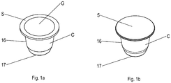
- FIGs 1 a and 1 b schematically show capsules C for producing beverages that can be packaged by means of the machine and/or the method according to the present invention.
- the capsules C can, for example, contain soluble and/or infusion products like, for example, ground coffee, milk and/or powdered cocoa, tea leaves or similar.
- the capsule shown in figure 1 a is open and comprises a capsule body 16 comprising a capsule bottom 17 and a side wall that define the containment volume of the capsule. On the opposite side to the capsule bottom 17, the capsule C is open so as, for example, to be able to insert the product from which the desired beverage is obtained.
- the side wall of the capsule comprises a projecting edge that defines a surface S on the opposite side to the capsule bottom 17.
- the projecting edge surrounds and also defines the opening G of the capsule.
- the capsule C shown in figure 1a is frusto-conical in shape, so that the surface S is circular, but alternatively the capsule C and therefore the surface S can have any other shape, for example polygonal.
- Figure 1b shows the capsule C of figure 1a closed by means of a closing element 5.
- the closing element 5 was applied to the projecting edge of the capsule.
- the closing element can preferably be welded to the projecting edge, for example thermo-welded.
- the closing element 5 can be glued to the projecting edge.
- the closing element 5 can be adapted for hermetically closing the capsule, so as to optimise the conservation of the organoleptic properties of the product contained in the capsule.
- the closing element 5 can be made of aluminium.
- the closing element 5 can for example be a filtering element, for example filter paper or similar. In this case, the closing element 5 prevents the product contained in the capsule C from coming out from the capsule, but allows for example the passage of gas and/or liquid through its surface.
- Figure 2 schematically illustrates a 3D view of a machine 1 for packaging capsules C for producing beverages according to an embodiment of the present invention.
- the machine 1 comprises a carousel 2 adapted for transporting the capsules C, housed on the carousel 2 in suitable seats 8, along a circular direction, during the packaging steps.
- the various operative stations of the machine 1 are positioned so as to operate on the capsules C housed in the seats 8 of the carousel 2.
- the circular direction of advancement of the machine is in the anti-clockwise direction and is schematically indicated by the arrow F.
- the carousel 2 rotates around its centre O.
- the rotation of the carousel 2 can, for example, be actuated by a first motor 12.
- the carousel 2 rotates in the anti-clockwise direction along the direction F.
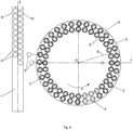
- Figure 2 shows that the seats 8 of the capsules C are arranged on the carousel 2 on two concentric circles A and B centred on the centre O of the carousel 2.
- the seats 8 can be arranged on the carousel 2 also on more than two concentric circles centred on the centre O of the carousel, for example on 3, 4, 5 or on a greater number of concentric circles.
- the seats 8 can be arranged on the two or more concentric circles in phase.
- the seats 8 can be arranged on the carousel 2 so that each n-th capsule CA(n) on the circle A, for example the outermost one, corresponds to the n-th capsule CB(n) on the circle B, for example the innermost one, adjacent to the n-th capsule CA(n).
- the corresponding seats 8, i.e. for the capsules CA(n) and CB(n), on the two concentric circles, respectively, are, in this way, located substantially along the same radius of the carousel 2 as shown in figure 3 or in figure 4 .
- the seats 8 are arranged side-by-side in pairs along the perimeter of the carousel 2 so as to form two concentric circles, an outer one A, i.e. with larger diameter, and an inner one B, i.e. with a smaller diameter, and so that the two corresponding seats of the same pair belonging to the two distinct circles are arranged substantially along the same radius of the carousel 2.
- This characteristic of the seats arranged in phase on the various circles can also be implemented with a number greater than two of concentric circles.
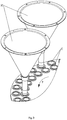
- the seats 8 can be arranged on the two or more concentric circles out of phase, as shown schematically in figure 5 .
- the seats 8 are side-by-side in pairs along the perimeter of the carousel 2 so as to form two concentric circles, an outer one A, i.e. with a larger diameter, and an inner one B, i.e.
- the shape of the seats 8 shown in the figures is circular, but they can be of any shape, for example polygonal, compatible with the shape of the capsules C to be packaged.
- the machine 1 shown in figure 2 also comprises a transportation device 3 for transporting a film 4, at least partially along a linear sliding direction X that lies on a plane parallel to the carousel 2.
- the expression "plane parallel to the carousel 2" means a plane parallel to the plane defined by the upper surface of the carousel 2 on which the seats 8 for the capsules are arranged.
- the device 3 can, for example, comprise a roller pulling system for unwinding the film 4 from an unwinding reel 25 to a winding reel 26. In the embodiment shown in figure 2 , the film 4 moves in the direction indicated by the arrow I.
- the transportation device 3 can comprise one or more pulling rollers 23 and one or more rollers that rotate idly
- the pulling rollers 23 are the rollers that actuate the movement of the film 4.
- the rollers that rotate idly 24 are rollers that rotate freely under the pulling action of the film 4 due to the action of the pulling rollers 23.
- the pulling roller 23 can be actuated by a second motor 13 of the machine 2 so as to unwind the film 4 from the unwinding reel 25 and to wind it back up into the winding reel 26.
- the motor 12 that sets the carousel 2 in motion is the same one that sets the transportation device 3 in motion.
- the rollers that rotate idly 24 can be arranged so as to define the path of the film 4 from the unwinding reel 25 to the winding reel 26.
- the system can comprise a first roller that rotates idly 24a and a second roller that rotate idly 24b arranged substantially on the same level so as to define at least one section of the path of the film 4 parallel to the plane of the carousel 2. In figure 2 this section is the section between the roller 24a and the roller 24b.
- the film 4 is preferably made of flexible material.
- the film 4 can be made of aluminium, paper, filter paper, multi-layer materials, impermeable materials, filtering materials, or similar.
- the film 4 comprises a first edge 9 and a second edge 10 that, in the section of path parallel to the carousel 2, are parallel to the sliding direction X.
- first edge 9 is meant to indicate the edge that, in this section of path, is furthest from the centre O of the carousel 2 with respect to the second edge 10, which, on the other hand, is closer to the centre O thereof.
- the relative position of the carousel 2 and of the film 4 in the section of path parallel to the carousel 2 can vary according to alternative embodiments of the present invention.
- the film 4 can at least partially or completely overlap the carousel 2.
- the film 4, in this section of its path in which it slides parallel to the carousel 2 may not overlap the carousel itself but slides laterally with respect to the carousel 2.
- Figures 2 , 3 and 5 show configurations in which the film 4 completely overlaps the carousel 2 in the section of path in which it slides parallel to the carousel 2.
- the transportation device 3 of the machine 1 is configured so that, during transportation, the film 4 overlaps the carousel 2 so that the first edge 9 of the film 4 coincides with a line parallel and close to the tangent to the carousel 2 parallel to the sliding direction X.
- the first edge 9 of the film 4 coincides with a line intersecting the carousel 2, parallel to the tangent to the carousel 2 parallel to the direction X.
- the transportation device 3 is configured so that, during transportation along the sliding direction X parallel to the carousel 2, the film 4 is arranged so that the second edge 10 is a distance from the centre O of the carousel 2 greater than the radius R of the carousel 2, so that the film 4 does not overlap the carousel 2. In this case, the film 4 slides laterally with respect to the carousel 2.
- the machine 1 also comprises cutting means 11, adapted for cutting closing elements 5, for closing the capsules C, from the film 4.
- the cutting means 11 can for example comprise blade shearing systems, toothed blade shearing systems, die punch or laser cutter. As shown in the figures, the cutting means 11 are configured so as to cut the closing elements 5 from the film 4 in the section in which the film 4 slides along the sliding direction X parallel to the carousel 2. When the cutting means 11 cut the closing elements 5 from the film 4 imprints for cutting the film 4 are made.
- the cutting means can comprise first cutting means 111 for a first row 71 of imprints of the cutting 6 on the film 4 and second cutting means 11II for a second row 711 of imprints of the cutting 6 on the film 4 (see for example figure 7 ).
- Figures 6a and 6b schematically show the imprints of the cutting of the closing elements in a film, respectively according to the state of the art and according to the present invention.
- the cutting means 11 are adapted for cutting the closing elements 5 so that the imprints 6 of the cutting of the closing elements 5 on the film 4 are arranged along two or more parallel rows, i.e. along at least one first row 7I and a second row 7II.
- the two rows 71 and 7II are also parallel to the sliding direction X.
- the two rows 7I and 7II are offset, so that the space occupied by two imprints 6 that are mutually adjacent and belong to the two distinct rows 71 and 7II, respectively, measured along the direction Y perpendicular to the sliding direction X, is less than or equal to the sum of the dimensions of each of the adjacent imprints 6, measured individually along the same direction Y.
- two imprints 6 of the cutting of the closing elements 5 that are mutually adjacent and belong to the two distinct rows 71 and 7II, respectively can be arranged along a direction E forming an angle ⁇ comprised between 35° and 55°, preferably between 40° and 50°, preferably 45°, with respect to the sliding direction X of the film 4.
- the cutting means 11 are adapted for cutting the closing elements 5 in the section in which the film 4 slides parallel to the carousel 2 along the sliding direction X so that the imprints 6 of the cutting of the closing elements 5 on the film 4 are arranged along two or more rows that are parallel to each other and offset, so that the space occupied by the two or more imprints 6 that are mutually adjacent and belong to the two or more distinct rows, respectively, measured along the direction Y perpendicular to the sliding direction X, is less than or equal to the sum of the dimensions of each of the adjacent imprints 6 measured individually along said same direction Y.
- the distribution of the imprints of the cutting on the film 4 is optimised so as to minimise the amount of film 4 not used to form the closing elements 5.
- the closing elements 5a are cut along parallel rows that are not offset.
- the spatial arrangement of the imprints 6a is such that the unused space between them is very wide and consequently the material of the film that is wasted is high.
- a further advantage of the optimised arrangement of the imprints 6 of the cutting of the closing elements 5 on the film 4 according to the present invention is that of allowing a film 4 to be used having a smaller width (i.e. dimension along the direction Y) with respect to the case in which the imprints 6 are arranged along parallel rows that are not offset to cut closing elements 5 having the same dimensions. This further reduces the amount of material of film 4 required.
- the imprints 6 can be circular in shape, as shown in figure 6b , in the case in which the surface S to be closed of the capsule C is circular.
- the imprints can be of any other shape, for example polygonal, compatible with the shape of the surface S of the capsule C to be closed.
- the imprints 6 are circular in shape with diameter D, they are arranged on the film 4 so that the lateral distance, i.e. measured along the direction Y, between the centres of adjacent imprints 6 belonging to different rows 7I and 7II, is less than or equal to the diameter D of a single imprint 6.
- the cutting means 11 can be arranged so as to cut closing elements 5 not adjacent to one another. If for example a first cutting means 11I cuts the n-th closing element 5I(n) of the row 71, a second cutting means 11II can be arranged so as to cut the (n+1)-th closing element 5II(n+1) of the row 7II and not the n-th closing element 5II(n) of the row 7II. Cutting means 11 arranged so as to cut closing elements 5 that are mutually adjacent, indeed, would have to be distanced apart, due to the bulk thereof, with the consequent increase in distance of the imprints 6 of the closing elements 5 on the film 4 and thus an increase in material waste.
- the transportation device 3 is configured so that the film 4 overlaps the carousel 2, the cutting means 11 arranged so as to cut closing elements 5 that are not adjacent to one another are also arranged so as to cut closing elements 5 that are applied to capsules C that are not adjacent to one another.
- the second cutting means 1111 cuts the (n+1)-th closing element 5II(n+1) of the row 7II, for the capsule CB(n+1) on the inner concentric circle B and not the n-th closing element 5II(n) of the row 7II, for the capsule CB(n) adjacent to the capsule CA(n).
- the closing means 21 are configured to apply the closing elements 5 to the capsules C when the capsules C are housed on the carousel 2.
- the closing means can comprise first closing means 211 for a first row A of seats 8 of capsules C on the carousel 2 and second cutting means 1111 for a second row B of seats 8 of capsules C on the carousel 2 (see for example figure 7 ).
- the closing means 5 are thermo-welded to the capsules by the closing means 21.
- the closing means 21 can thus comprise welding means, for example thermowelders.
- the closing means 21 are at the cutting means 11.
- the first closing means 211 are at the first cutting means 11I and the second closing means 2111 are at the second cutting means 11II.
- the closing means 5 can be cut from the film 4 and applied to the capsules C in a single operation.
- the shape of the cutting means 11 and of the closing means 21 can be any one that is compatible with the shape of the surface S of the capsule C to be closed.
- the closing means 21 can be arranged so as to apply the closing elements 5 to capsules C that are not adjacent to one another in an analogous manner to what is explained above with reference to the cutting means. If for example the first closing means 211 apply a closing element 5 to the capsule CA(n) on the outermost concentric circle A, the second welding means 21II are positioned to apply a closing element 5 to the capsule CB(n+1) on the inner concentric circle B and not to the capsule CB(n) adjacent to the capsule CA(n).
- the spatial arrangement of the imprints 6 on the film 4 corresponds to the spatial arrangement of the seats 8 of the capsules C on the carousel 2. More specifically, the seats 8 of the capsules C are arranged so as to overlap the imprints 6 on the film 4 in the direction Y in the point of tangency between the carousel 2 and the first edge 9 of the film 4. In this way, the closing elements 5 can be cut and applied to the capsule C in a single operation. It should also be noted that in this case the angular speed with which the carousel 2 rotates is synchronous with the speed with which the film 4 slides, so that as the film 4 slides, the capsules C in the seats 8 suitably rotate.
- the spatial arrangement of the imprints 6 on the film 4 may not correspond to the spatial arrangement of the seats 8 of the capsules C on the carousel 2 even if in the figures this correspondence is shown.
- the closing elements 5 are first cut from the film 4 and are then transported to the seats 8 to be applied to the capsules C to close them. In this transportation step it is possible to correct any discrepancy between the spatial arrangement of the imprints 6 on the film 4 and the spatial arrangement of the seats 8 on the carousel 2.
- the machine 1 according to the present invention can also comprise transportation means for transporting onto the carousel 2 the open capsules C that must be packaged and for positioning them in the seats 8 of the carousel 2.
- Figure 8 shows for example a pair of conveyor belts 14, adapted for transporting the capsules C, oriented in an orderly manner, close to the carousel 2.
- the conveyor belts 14 can, for example, be positioned, with respect to the carousel 2, so that the capsules C, at the end of their journey along the conveyor belts 14, fall automatically into the seats 8 of the carousel.
- a first conveyor belt is adapted for transporting the capsules C into the seats 8 of a first circle whereas a second conveyor belt is adapted for transporting the capsules C into the seats 8 of the second circle.
- the machine 1 can further comprise mobile elements 15, for example mobile arms or thrusting punches for the insertion of the capsules C in the seats 8 on the carousel 2.
- the open capsules transported by the conveyor belts 14 can for example come from a tank of open capsules or directly from a machine that produces the open capsules.
- An example of the positioning of the conveyor belts in the architecture of the machine 1 is shown schematically in figure 2 .
- the machine 1 can also comprise dosers 20, for filling the capsules C with the desired soluble and/or infusion product when the capsules are housed in the seats 8 of the carousel 2, in the case in which they arrive on the carousel 2 empty.
- the machine comprises two dosers 20, i.e. one for each circle of seats 8 of the carousel 2, for the two dosers to be arranged out of phase with respect to the direction of rotation of the carousel.
- one of the two dosers is further upstream in the direction of rotation of the carousel with respect to the second.
- the system can comprise different numbers of dosers, for example the system can comprise a single doser with many outlets, one for each of the circles of seats of the carousel. Alternatively, the system can comprise as many dosers as there are circles of seats of the carousel.
- An example of the positioning of the dosers 20 in the architecture of the machine 1 is shown schematically in figure 2 .
- the dosers can be arranged between the transportation means of the capsules and the closing means along the direction F of advancement of the machine.
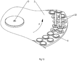
- Figure 10 shows that the machine 1 according to the present invention can further comprise extractor means 22, for discharging the capsules C from the carousel 2, once they have been closed with the closing elements 5.
- the extractors 22 preferably comprise suction cups, adapted for hooking the capsules C and removing them suitably from their seats 8.
- the suction cups can for example grip onto the closing elements 5 of the capsules.
- An example of positioning of the extractor means 22 in the architecture of the machine 1 is shown schematically in figure 2 .
- the extractor means can be arranged between the closing means and the transportation means of the capsules along the direction F of advancement of the machine.
- the machine 1 shown in figure 2 thus comprises a carousel 2 comprising seats 8 for the capsules C so as to transport the capsules along a circular direction during packaging, transportation means 14 for transporting open capsules towards the carousel 2 and for inserting them in the seats 8 of the carousel 2, a transportation device 3 for transporting a film 4 along a linear sliding direction X that lies on a plane parallel to the carousel, cutting means 11 for cutting closing elements 5 from the film in the section in which it slides along the linear sliding direction X and closing means 21 configured to apply the closing elements 5 to the capsules C when the capsules are housed on the carousel 2, wherein the cutting means 11 are adapted for cutting the closing elements 5 so that the imprints 6 of the cutting of the closing elements 5 on the film 4 are arranged along two or more rows 7 that are parallel to each other and offset, so that the space occupied by two or more imprints 6 that are mutually adjacent and belong to the two or more distinct rows 7, respectively, measured along the direction Y perpendicular
- the machine 1 can optionally comprise dosers 20 to fill the capsules housed in the seats 8 of the carousel 2.
- the dosers 20 can advantageously be arranged between the transportation means 14 and the closing means 21 along the circular direction of advancement F of the machine defined by the carousel 2.
- the machine 1 can also further comprise extraction means 22 to extract the packaged capsules from the carousel 2.
- extraction means 22 can be advantageously arranged between the closing means 21 and the transportation means 14 along the circular direction of advancement F of the machine defined by the carousel 2.
- a method is also provided for packaging capsules C for producing beverages, for example espresso, by means of a machine 1 comprising a carousel 2 adapted for transporting capsules C, housed on the carousel 2 in suitable seats 8, along a circular direction and a transportation device 3 for transporting a film 4 along a linear sliding direction X.
- a machine 1 comprising a carousel 2 adapted for transporting capsules C, housed on the carousel 2 in suitable seats 8, along a circular direction and a transportation device 3 for transporting a film 4 along a linear sliding direction X.
- the transportation of the capsules along the circular direction by means of the carousel during packaging indicates that the capsules are transported by the carousel along the circular direction of advancement so as to carry out the various steps of the packaging of the capsules while the capsules are housed on the carousel.
- the carousel with its rotation in the circular direction of advancement of the machine, allows the capsules to be brought to the various operative stations of the machine so as to carry out the steps of the method for packaging the capsules while the capsules are housed on the carousel.
- the carousel 2 comprising the seats 8, the transportation device 3, the film 4, the cutting means 11 and the welding means 21 can have the characteristics already described earlier, with reference to the machine 1 for simultaneously packaging a plurality of capsules C for producing beverages.
- the capsules C are loaded onto the carousel 2. More specifically, the capsules C are brought into the seats 8 on the carousel 2. For example, this can occur by means of one or more conveyor belts 14, which carry the capsules C, oriented in an orderly manner and open, close to the carousel 2.
- the conveyor belts 14 can, for example, be positioned, with respect to the carousel 2, so that the capsules C, at the end of their journey, fall automatically in their seats 8.
- An example of this step is shown schematically in figure 8 .
- Mobile arms 15 can, for example, take care of the subsequent insertion of the capsules C in the seats 8 of the carousel 2.
- the capsules C Before the capsules C are closed, they can be filled with the soluble and/or infusion product P for producing the desired beverage, by means of, for example, the use of suitable dosers 20.
- the dosers 20 are shaped like inverted cones, but any other shape is suitable for being used.
- the dosers 20 ensure that the correct amount of product that must be contained in the capsule C itself is deposited inside the capsule C.
- This step of the method an example of which is shown schematically in figure 9 , only takes place in the case in which the capsules C arrive on the carousel 2 empty. In this case, if the surface S of the capsule C is the only open surface of the capsule C, it is, indeed, necessary to fill them before the surface S is closed by the closing elements 5.
- the closing elements 5, previously cut by the cutting means 11 from the film 4, are preferably applied to the capsules C, so as to close, for example hermetically, the surface S.
- the application of the closing elements 5 can take place, for example, by thermowelding, by means of the welding means 21.
- An example of this step is schematically illustrated in figure 7 in the case in which the film 4 and the carousel 2 overlap. In this case, indeed, in figure 7 it is also possible to see the step of cutting the closing elements 5 from the film 4.
- the capsules C are preferably discharged from the carousel 2, by means of the extractors 22.
- the extractors 22 can comprise suction cups adapted for gripping the capsules C and removing them suitably from their seats 8. In this way, the seats 8 are freed from the closed capsules C, so that new open capsules C can be loaded onto the carousel 2.
- An example of this step is schematically illustrated in figure 10 .
- the shape of the surface S of the capsules C and therefore the shape of the imprints 6 that the cutting means 11 produce on the film 4 can be whatever is suitable.
- cases have been shown in which the imprints of the cuts are arranged on two rows that are parallel and offset, but the number of rows can be greater than two. It is clear that in analogy also the number of concentric centres A, B on which the seats 8 for the capsules C on the carousel 2 are arranged can be greater than two.
Landscapes
- Engineering & Computer Science (AREA)
- Mechanical Engineering (AREA)
- Apparatus For Making Beverages (AREA)
Claims (20)
- Maschine (1) zum gleichzeitigen Verpacken einer Vielzahl von Kapseln (C) zum Herstellen von Getränken, beispielsweise Espresso, die ein Karussell (2) umfasst, das zum Transportieren der Kapseln (C) in einer Kreis-Richtung (F) beim Verpacken eingerichtet ist, wobei die Kapseln (C) an dem Karussell (2) in geeigneten Aufnahmen (8) aufgenommen sind, und eine Transportvorrichtung (3) zum Transportieren einer Folie (4) in einer geraden Gleit-Richtung (X); wobei die Maschine (1) des Weiteren Schneideinrichtungen (11) umfasst, die zum Schneiden von Verschluss-Elementen (5) zum Verschließen einer Oberfläche (S) der Kapseln (C) aus der Folie (4) eingerichtet sind, die Gleit-Richtung (X) in einer Ebene (P) parallel zu dem Karussell (2) liegt, die Schneideinrichtungen (11) so eingerichtet sind, dass sie die Verschluss-Elemente (5) so schneiden, dass die Eindrücke (6) des Einschnitts der Verschluss-Elemente (5) auf der Folie (4) in zwei oder mehr Reihen (7) parallel zueinander angeordnet sind, dadurch gekennzeichnet, dass die Eindrücke (6) so zueinander versetzt sind, dass der Raum, der von zwei oder mehr Eindrücken (6) eingenommen wird, die benachbart zueinander sind und jeweils zu zwei oder mehr einzelnen Reihen (7) gehören, gemessen in der Richtung (Y) senkrecht zu der Gleit-Richtung (X), kleiner ist als oder genauso groß wie die Summe der individuell in der gleichen Richtung (Y) gemessenen Abmessungen jedes der benachbarten Eindrücke (6), und wobei die Maschine (1) des Weiteren Verschluss-Einrichtungen (21) umfasst, die so ausgeführt sind, dass sie die Verschluss-Elemente (5) auf die Kapseln (C) aufbringen, wenn die Kapseln (C) an dem Karussell (2) aufgenommen sind.
- Maschine (1) nach Anspruch 1, dadurch gekennzeichnet, dass die räumliche Anordnung der Eindrücke (6) auf der Folie (4) der räumlichen Anordnung der Aufnahmen (8) für die Kapseln (C) an dem Karussell (2) entspricht.
- Maschine (1) nach einem der vorangehenden Ansprüche, dadurch gekennzeichnet, dass zwei oder mehr der Eindrücke (6) zum Schneiden der Verschluss-Elemente (5), die zueinander benachbart sind und jeweils zu den zwei oder mehr einzelnen Reihen gehören, in einer Richtung (I) angeordnet sind, die einen Winkel (α) in Bezug auf die Gleit-Richtung (X) der Folie (4) bildet, der zwischen 35° und 55°, vorzugsweise zwischen 40° und 50°, vorzugsweise 45° beträgt.
- Maschine (1) nach einem der vorangehenden Ansprüche, dadurch gekennzeichnet, dass die Transportvorrichtung (3) für die Folie (4) so ausgeführt ist, dass die Folie (4) beim Transport in der Gleit-Richtung (X) das Karussell (2) wenigstens teilweise überlappt, beispielsweise so, dass die erste Kante (9) der Folie (4) mit einer Linie parallel zu und nahe an der Tangente des Karussells (2) parallel zu der Gleit-Richtung (X) deckungsgleich ist, wobei die erste Kante (9) der Folie (4) die Kante (9) der Folie (4) parallel zu der Gleit-Richtung (X) ist, die weiter von der Mitte (O) des Karussells (2) entfernt ist als die zweite Kante (10) der Folie (4).
- Maschine (1) nach einem der Ansprüche 1 bis 3, dadurch gekennzeichnet, dass die Transportvorrichtung (3) für die Folie (4) so ausgeführt ist, dass die Folie beim Transport in der Gleit-Richtung das Karussell (2) nicht überlappt, beispielsweise so, dass die Folie (4) so angeordnet ist, dass die zweite Kante (10) der Folie (4), das heißt, die Kante (10), die sich in Bezug auf die erste Kante (9) der Folie (4) am nächsten an der Mitte (O) des Karussells (2) befindet, einen Abstand zu der Mitte (O) des Karussells (2) hat, der größer ist als der Radius (R) des Karussells (2).
- Maschine (1) nach einem der vorangehenden Ansprüche, dadurch gekennzeichnet, dass die Aufnahmen (8) für die Kapseln (C) auf zwei oder mehr konzentrischen Kreisen (A, B) angeordnet sind, die auf den Mittelpunkt (O) des Karussells (2) zentriert sind.
- Maschine nach Anspruch 6, dadurch gekennzeichnet, dass die Aufnahmen (8) in Phase auf den zwei konzentrischen Kreisen (A, B) angeordnet sind, das heißt so, dass jede n-te Kapsel (CA(n)) auf einem äußersten Kreis (A) mit der n-ten Kapsel (CB(n)) auf einem innersten Kreis (B) deckungsgleich ist, die benachbart zu der n-ten Kapsel (CA(n)) auf dem äußersten Kreis (A) ist.
- Maschine (1) nach Anspruch 6, dadurch gekennzeichnet, dass die Aufnahmen (8) phasenversetzt auf den zwei konzentrischen Kreisen (A, B) angeordnet sind, das heißt so, dass jede der Aufnahmen (8), beispielsweise für die Kapsel (CA(n)), eines der Kreise (A, B), zwischen zwei Aufnahmen (8), beispielsweise für die Kapseln (CB(n-1)) und (CB(n)), des anderen Kreises (B, A) positioniert ist.
- Maschine (1) nach einem der vorangehenden Ansprüche, dadurch gekennzeichnet, dass die Schneideinrichtungen (11) so angeordnet sind, dass sie Verschluss-Elemente (5) schneiden, die nicht benachbart zueinander sind.
- Maschine (1) nach einem der vorangehenden Ansprüche, dadurch gekennzeichnet, dass die Verschluss-Einrichtungen (21) so angeordnet sind, dass sie Verschluss-Elemente (5) auf Kapseln (C) aufbringen, die nicht benachbart zueinander sind.
- Verfahren zum gleichzeitigen Verpacken einer Vielzahl von Kapseln (C) zum Herstellen von Getränken, beispielsweise Espresso, mittels einer Maschine (1), die ein Karussell (2), das zum Transportieren der Kapseln (C), die an dem Karussell (2) in geeigneten Aufnahmen (8) aufgenommen sind, in einer Kreis-Richtung (F) und eine Transportvorrichtung (3) zum Transportieren einer Folie (4) in einer geraden Gleit-Richtung (X) umfasst, dadurch gekennzeichnet, dass es die folgenden Schritte umfasst:Transportieren der Kapseln (C) in der Kreis-Richtung mittels des Karussells (2) beim Verpacken;Transportieren der Folie (4) in der linearen Gleit-Richtung (X) auf einer Ebene parallel zu dem Karussell (2) mittels der Transportvorrichtung (3);Schneiden von Verschluss-Elementen (5), die zum Verschließen einer Oberfläche (S) der Kapseln (C) eingerichtet sind, aus der Folie (4), so dass die Eindrücke (6) zum Schneiden der Verschluss-Elemente (5) auf der Folie (4) in zwei oder mehr Reihen (7) parallel zueinander und versetzt so angeordnet sind, dass der Raum, der von zwei oder mehr Eindrücken (6) eingenommen wird, die benachbart zueinander sind und jeweils zu zwei oder mehr einzelnen Reihen (7) gehören, gemessen in der Richtung (Y) senkrecht zu der Gleit-Richtung (X), kleiner ist als oder genauso groß wie die Summe der individuell in der gleichen Richtung (Y) gemessenen Abmessungen jedes der benachbarten Eindrücke (6),Aufbringen der Verschluss-Elemente (5) auf die Kapseln (C), um sie zu verschließen, wenn die Kapseln (C) an dem Karussell (2) aufgenommen sind.
- Verfahren nach Anspruch 11, dadurch gekennzeichnet, dass die räumliche Anordnung der Eindrücke (6) auf der Folie (4) der räumlichen Anordnung der Aufnahmen (8) für die Kapseln (C) an dem Karussell (2) entspricht.
- Verfahren nach einem der Ansprüche 11 oder 12, dadurch gekennzeichnet, dass zwei oder mehr der Eindrücke, (6) zum Schneiden der Verschluss-Elemente (5), die zueinander benachbart sind und jeweils zu zwei oder mehr der einzelnen Reihen gehören, so hergestellt werden, dass sie in einer Richtung (I) angeordnet sind, die einen Winkel (α) in Bezug auf die Gleit-Richtung (X) der Folie (4) bildet, der zwischen 35° und 55°,, vorzugsweise zwischen 40° und 50°, vorzugsweise 45° beträgt.
- Verfahren nach einem der Ansprüche 11 bis 13, dadurch gekennzeichnet, dass Schneiden der Verschluss-Elemente (5) an den Aufnahmen (8) stattfindet.
- Verfahren nach einem der Ansprüche 11 bis 13, dadurch gekennzeichnet, dass Schneiden der Verschluss-Elemente (5) nicht an den Aufnahmen (8) stattfindet, und die Verschluss-Elemente (5) anschließend zu den Aufnahmen (8) transportiert werden, um die Kapseln (C) zu verschließen.
- Verfahren nach einem der Ansprüche 11 bis 15, dadurch gekennzeichnet, dass die Aufnahmen (8) für die Kapseln (C) auf zwei oder mehr konzentrischen Kreisen (A, B) angeordnet sind, die auf den Mittelpunkt (O) des Karussells (2) zentriert sind.
- Verfahren nach Anspruch 16, dadurch gekennzeichnet, dass die Aufnahmen (8) in Phase auf den zwei konzentrischen Kreisen (A, B) angeordnet sind, das heißt so, dass jede n-te Kapsel (CA(n)) auf einem äußersten Kreis (A) mit der n-ten Kapsel (CB(n)) auf einem innersten Kreis (B) deckungsgleich ist, die benachbart zu der n-ten Kapsel (CA(n)) auf dem äußersten Kreis (A) ist.
- Verfahren nach Anspruch 16, dadurch gekennzeichnet, dass die Aufnahmen (8) phasenversetzt auf den zwei konzentrischen Kreisen (A, B) angeordnet sind, das heißt so, dass jede der Aufnahmen (8), beispielsweise für die Kapsel (CA(n)), eines der Kreise (A, B), zwischen zwei Aufnahmen (8), beispielsweise für die Kapseln (CB(n-1)) und (CB(n)), des anderen Kreises (B, A) positioniert ist.
- Verfahren nach einem der Ansprüche 11 bis 18, dadurch gekennzeichnet, dass die Folie (4) flexibles Material umfasst.
- Verfahren nach einem der Ansprüche 11 bis 19, dadurch gekennzeichnet, dass es des Weiteren den folgenden Schritt umfasst:Füllen der Kapseln (C) mit dem löslichen und/oder Aufgusserzeugnis (P) zum Herstellen des gewünschten Getränkes, wenn die Kapseln (C) an dem Karussell (2) aufgenommen sind.
Applications Claiming Priority (1)
| Application Number | Priority Date | Filing Date | Title |
|---|---|---|---|
| ITBO20140734 | 2014-12-29 |
Publications (2)
| Publication Number | Publication Date |
|---|---|
| EP3040285A1 EP3040285A1 (de) | 2016-07-06 |
| EP3040285B1 true EP3040285B1 (de) | 2017-03-01 |
Family
ID=52597047
Family Applications (1)
| Application Number | Title | Priority Date | Filing Date |
|---|---|---|---|
| EP15202092.1A Active EP3040285B1 (de) | 2014-12-29 | 2015-12-22 | Verpackungsmaschine und verfahren zur herstellung von getränkekapseln |
Country Status (1)
| Country | Link |
|---|---|
| EP (1) | EP3040285B1 (de) |
Families Citing this family (10)
| Publication number | Priority date | Publication date | Assignee | Title |
|---|---|---|---|---|
| IT201700012521A1 (it) * | 2017-02-06 | 2018-08-06 | Gd Spa | Sistema di chiusura di contenitori mediante elementi di chiusura ottenuti da un foglio continuo di materiale per una macchina confezionatrice a passo doppio. |
| IT201800000927A1 (it) | 2018-01-15 | 2019-07-15 | T M E S R L | Dispositivo e metodo di applicazione di uno spezzone di film di materiale ad un contenitore |
| CN109292126B (zh) * | 2018-11-21 | 2024-11-26 | 苏州英派克自动化设备有限公司 | 一种烟用杯状胶囊注液封装装置 |
| IT202000018850A1 (it) | 2020-07-31 | 2022-01-31 | Gd Spa | Unità e metodo di movimentazione e riempimento di un contenitore ed apparato di produzione di articoli ad essi correlati |
| IT202000018790A1 (it) * | 2020-07-31 | 2022-01-31 | Gd Spa | Unità di movimentazione di articoli |
| BR112023001270A2 (pt) * | 2020-08-05 | 2023-04-04 | Gd Spa | Dispositivo e processo de transferência, e aparelho de embalagem |
| CA3183610A1 (en) * | 2020-08-05 | 2022-02-10 | G.D S.P.A. | Transfer device and process |
| JP2023536311A (ja) * | 2020-08-07 | 2023-08-24 | ジ・ディ・ソシエタ・ペル・アチオニ | 構成要素を物品に結合させるための結合デバイス |
| US20250026510A1 (en) * | 2021-11-09 | 2025-01-23 | Compopack S.R.L. | Machine for the production of disposable packages of products, particularly of ground or powdery products |
| IT202200024315A1 (it) * | 2022-11-25 | 2024-05-25 | Tecmes Srl | Stazione di formatura di filtri per capsule filtranti di caffè |
Citations (5)
| Publication number | Priority date | Publication date | Assignee | Title |
|---|---|---|---|---|
| DE1511620A1 (de) | 1966-05-18 | 1969-09-11 | Hamac Hansella Gmbh | Verpackungsanlage mit einer Ziehpresse zum Herstellen der Verpackungsbehaelter und einer UEbergabeeinrichtung |
| DE2534634A1 (de) | 1974-08-02 | 1976-02-12 | Europ Rech Expl Commerce | Verfahren zur fertigung von mit einer dichtung ausgekleideten kapseln fuer das verschliessen von flaschen |
| DE2602566A1 (de) | 1975-01-30 | 1976-08-05 | Sumitomo Bakelite Co | Geraet zum abdichten der oberteile von behaeltern |
| EP1312548A1 (de) | 2001-07-26 | 2003-05-21 | Erca Formseal | Vorrichtung zum Schneiden einer Reihe von Membranverschlüssen aus einer Bahn und zur Fixierung dieser auf einer Reihe von gefüllten Behältern |
| EP1564143A1 (de) | 2004-02-17 | 2005-08-17 | Hans Rychiger AG | Vorrichtung zum Aufbringen von Folienteilen aus einem Folienband auf Objekte |
Family Cites Families (2)
| Publication number | Priority date | Publication date | Assignee | Title |
|---|---|---|---|---|
| AT505545B1 (de) * | 2007-12-20 | 2009-02-15 | Christian Marek | Mechanische befüllungsmaschine |
| IT1396121B1 (it) * | 2009-10-02 | 2012-11-16 | Conti | Macchina per il confezionamento di capsule con prodotti da infusione con gruppo di chiusura. |
-
2015
- 2015-12-22 EP EP15202092.1A patent/EP3040285B1/de active Active
Patent Citations (5)
| Publication number | Priority date | Publication date | Assignee | Title |
|---|---|---|---|---|
| DE1511620A1 (de) | 1966-05-18 | 1969-09-11 | Hamac Hansella Gmbh | Verpackungsanlage mit einer Ziehpresse zum Herstellen der Verpackungsbehaelter und einer UEbergabeeinrichtung |
| DE2534634A1 (de) | 1974-08-02 | 1976-02-12 | Europ Rech Expl Commerce | Verfahren zur fertigung von mit einer dichtung ausgekleideten kapseln fuer das verschliessen von flaschen |
| DE2602566A1 (de) | 1975-01-30 | 1976-08-05 | Sumitomo Bakelite Co | Geraet zum abdichten der oberteile von behaeltern |
| EP1312548A1 (de) | 2001-07-26 | 2003-05-21 | Erca Formseal | Vorrichtung zum Schneiden einer Reihe von Membranverschlüssen aus einer Bahn und zur Fixierung dieser auf einer Reihe von gefüllten Behältern |
| EP1564143A1 (de) | 2004-02-17 | 2005-08-17 | Hans Rychiger AG | Vorrichtung zum Aufbringen von Folienteilen aus einem Folienband auf Objekte |
Non-Patent Citations (3)
| Title |
|---|
| "590 - New GIMA Capsule Filling machine", IMA CORPORATE, 10 October 2014 (2014-10-10), XP055442825, Retrieved from the Internet <URL:www.ima.it/590-new-gima-caspule-filling-machine/> [retrieved on 20171113] |
| "Low Speed Capsule Filling Machine", IMA GIMA 590, October 2014 (2014-10-01), XP055434434 |
| "Tecnologie per il dosaggio di precisione", PACKAGING OBSERVER, 9 November 2014 (2014-11-09), XP055442826, Retrieved from the Internet <URL:www.packagingobserver.com/tecnologie-per-il-dosaggio-di-precisione/> [retrieved on 20171113] |
Also Published As
| Publication number | Publication date |
|---|---|
| EP3040285A1 (de) | 2016-07-06 |
Similar Documents
| Publication | Publication Date | Title |
|---|---|---|
| EP3040285A1 (de) | Verpackungsmaschine und verfahren zur herstellung von getränkekapseln | |
| EP2895396B1 (de) | Maschine und verfahren zum verpacken von kapseln in mehrkapselverpackungen | |
| CN104995094B (zh) | 用于制造一次性饮料囊的饮料囊机 | |
| CN105408211B (zh) | 制造胶囊的包装机及方法 | |
| CN104159823B (zh) | 用于制造一次性囊的饮料囊制造机 | |
| EP3164334B1 (de) | Maschine und verfahren zur herstellung von kapseln für getränke | |
| CN105452109B (zh) | 用来包装用于饮料的一次性小容器的机器 | |
| EP4192744B1 (de) | Herstellungsvorrichtung und herstellungsverfahren für kapseln vom infusionstyp | |
| EP4037977B1 (de) | Verpackungsmaschine zur herstellung von filterbeuteln mit aufgussprodukten | |
| US20230234738A1 (en) | Transfer device and transfer process | |
| JP2023536309A (ja) | 梱包装置およびプロセス | |
| US12338026B2 (en) | Transfer device and process | |
| WO2016075604A1 (en) | Machine and method for packaging containers for beverage and package obtained thereby | |
| EP4273058B1 (de) | Maschine und verbessertes verpackungsverfahren eines einwegspenders mit integriertem strohhalm | |
| EP3426561B1 (de) | Maschine zur herstellung von filterbeuteln mit aufgussprodukten | |
| WO2022172189A1 (en) | A packaging system | |
| HK1202499B (en) | Beverage capsule machine for making single use capsules |
Legal Events
| Date | Code | Title | Description |
|---|---|---|---|
| PUAI | Public reference made under article 153(3) epc to a published international application that has entered the european phase |
Free format text: ORIGINAL CODE: 0009012 |
|
| AK | Designated contracting states |
Kind code of ref document: A1 Designated state(s): AL AT BE BG CH CY CZ DE DK EE ES FI FR GB GR HR HU IE IS IT LI LT LU LV MC MK MT NL NO PL PT RO RS SE SI SK SM TR |
|
| AX | Request for extension of the european patent |
Extension state: BA ME |
|
| 17P | Request for examination filed |
Effective date: 20160728 |
|
| RBV | Designated contracting states (corrected) |
Designated state(s): AL AT BE BG CH CY CZ DE DK EE ES FI FR GB GR HR HU IE IS IT LI LT LU LV MC MK MT NL NO PL PT RO RS SE SI SK SM TR |
|
| GRAP | Despatch of communication of intention to grant a patent |
Free format text: ORIGINAL CODE: EPIDOSNIGR1 |
|
| RIC1 | Information provided on ipc code assigned before grant |
Ipc: B65B 65/00 20060101ALI20160817BHEP Ipc: B65B 43/50 20060101ALI20160817BHEP Ipc: B65B 7/16 20060101ALI20160817BHEP Ipc: B65B 29/02 20060101AFI20160817BHEP |
|
| INTG | Intention to grant announced |
Effective date: 20160912 |
|
| RIN1 | Information on inventor provided before grant (corrected) |
Inventor name: RAPPARINI, ULISSE |
|
| STAA | Information on the status of an ep patent application or granted ep patent |
Free format text: STATUS: GRANT OF PATENT IS INTENDED |
|
| GRAS | Grant fee paid |
Free format text: ORIGINAL CODE: EPIDOSNIGR3 |
|
| GRAA | (expected) grant |
Free format text: ORIGINAL CODE: 0009210 |
|
| STAA | Information on the status of an ep patent application or granted ep patent |
Free format text: STATUS: THE PATENT HAS BEEN GRANTED |
|
| AK | Designated contracting states |
Kind code of ref document: B1 Designated state(s): AL AT BE BG CH CY CZ DE DK EE ES FI FR GB GR HR HU IE IS IT LI LT LU LV MC MK MT NL NO PL PT RO RS SE SI SK SM TR |
|
| REG | Reference to a national code |
Ref country code: GB Ref legal event code: FG4D |
|
| REG | Reference to a national code |
Ref country code: CH Ref legal event code: EP Ref country code: AT Ref legal event code: REF Ref document number: 870968 Country of ref document: AT Kind code of ref document: T Effective date: 20170315 |
|
| REG | Reference to a national code |
Ref country code: IE Ref legal event code: FG4D |
|
| REG | Reference to a national code |
Ref country code: DE Ref legal event code: R096 Ref document number: 602015001666 Country of ref document: DE |
|
| REG | Reference to a national code |
Ref country code: CH Ref legal event code: NV Representative=s name: KIRKER AND CIE S.A., CH |
|
| REG | Reference to a national code |
Ref country code: NL Ref legal event code: MP Effective date: 20170301 |
|
| REG | Reference to a national code |
Ref country code: LT Ref legal event code: MG4D |
|
| REG | Reference to a national code |
Ref country code: AT Ref legal event code: MK05 Ref document number: 870968 Country of ref document: AT Kind code of ref document: T Effective date: 20170301 |
|
| PG25 | Lapsed in a contracting state [announced via postgrant information from national office to epo] |
Ref country code: FI Free format text: LAPSE BECAUSE OF FAILURE TO SUBMIT A TRANSLATION OF THE DESCRIPTION OR TO PAY THE FEE WITHIN THE PRESCRIBED TIME-LIMIT Effective date: 20170301 Ref country code: NO Free format text: LAPSE BECAUSE OF FAILURE TO SUBMIT A TRANSLATION OF THE DESCRIPTION OR TO PAY THE FEE WITHIN THE PRESCRIBED TIME-LIMIT Effective date: 20170601 Ref country code: GR Free format text: LAPSE BECAUSE OF FAILURE TO SUBMIT A TRANSLATION OF THE DESCRIPTION OR TO PAY THE FEE WITHIN THE PRESCRIBED TIME-LIMIT Effective date: 20170602 Ref country code: HR Free format text: LAPSE BECAUSE OF FAILURE TO SUBMIT A TRANSLATION OF THE DESCRIPTION OR TO PAY THE FEE WITHIN THE PRESCRIBED TIME-LIMIT Effective date: 20170301 Ref country code: LT Free format text: LAPSE BECAUSE OF FAILURE TO SUBMIT A TRANSLATION OF THE DESCRIPTION OR TO PAY THE FEE WITHIN THE PRESCRIBED TIME-LIMIT Effective date: 20170301 |
|
| PG25 | Lapsed in a contracting state [announced via postgrant information from national office to epo] |
Ref country code: AT Free format text: LAPSE BECAUSE OF FAILURE TO SUBMIT A TRANSLATION OF THE DESCRIPTION OR TO PAY THE FEE WITHIN THE PRESCRIBED TIME-LIMIT Effective date: 20170301 Ref country code: SE Free format text: LAPSE BECAUSE OF FAILURE TO SUBMIT A TRANSLATION OF THE DESCRIPTION OR TO PAY THE FEE WITHIN THE PRESCRIBED TIME-LIMIT Effective date: 20170301 Ref country code: RS Free format text: LAPSE BECAUSE OF FAILURE TO SUBMIT A TRANSLATION OF THE DESCRIPTION OR TO PAY THE FEE WITHIN THE PRESCRIBED TIME-LIMIT Effective date: 20170301 Ref country code: ES Free format text: LAPSE BECAUSE OF FAILURE TO SUBMIT A TRANSLATION OF THE DESCRIPTION OR TO PAY THE FEE WITHIN THE PRESCRIBED TIME-LIMIT Effective date: 20170301 Ref country code: LV Free format text: LAPSE BECAUSE OF FAILURE TO SUBMIT A TRANSLATION OF THE DESCRIPTION OR TO PAY THE FEE WITHIN THE PRESCRIBED TIME-LIMIT Effective date: 20170301 Ref country code: BG Free format text: LAPSE BECAUSE OF FAILURE TO SUBMIT A TRANSLATION OF THE DESCRIPTION OR TO PAY THE FEE WITHIN THE PRESCRIBED TIME-LIMIT Effective date: 20170601 |
|
| PG25 | Lapsed in a contracting state [announced via postgrant information from national office to epo] |
Ref country code: NL Free format text: LAPSE BECAUSE OF FAILURE TO SUBMIT A TRANSLATION OF THE DESCRIPTION OR TO PAY THE FEE WITHIN THE PRESCRIBED TIME-LIMIT Effective date: 20170301 |
|
| PG25 | Lapsed in a contracting state [announced via postgrant information from national office to epo] |
Ref country code: RO Free format text: LAPSE BECAUSE OF FAILURE TO SUBMIT A TRANSLATION OF THE DESCRIPTION OR TO PAY THE FEE WITHIN THE PRESCRIBED TIME-LIMIT Effective date: 20170301 Ref country code: EE Free format text: LAPSE BECAUSE OF FAILURE TO SUBMIT A TRANSLATION OF THE DESCRIPTION OR TO PAY THE FEE WITHIN THE PRESCRIBED TIME-LIMIT Effective date: 20170301 Ref country code: CZ Free format text: LAPSE BECAUSE OF FAILURE TO SUBMIT A TRANSLATION OF THE DESCRIPTION OR TO PAY THE FEE WITHIN THE PRESCRIBED TIME-LIMIT Effective date: 20170301 Ref country code: SK Free format text: LAPSE BECAUSE OF FAILURE TO SUBMIT A TRANSLATION OF THE DESCRIPTION OR TO PAY THE FEE WITHIN THE PRESCRIBED TIME-LIMIT Effective date: 20170301 |
|
| REG | Reference to a national code |
Ref country code: DE Ref legal event code: R026 Ref document number: 602015001666 Country of ref document: DE |
|
| PG25 | Lapsed in a contracting state [announced via postgrant information from national office to epo] |
Ref country code: SM Free format text: LAPSE BECAUSE OF FAILURE TO SUBMIT A TRANSLATION OF THE DESCRIPTION OR TO PAY THE FEE WITHIN THE PRESCRIBED TIME-LIMIT Effective date: 20170301 Ref country code: IS Free format text: LAPSE BECAUSE OF FAILURE TO SUBMIT A TRANSLATION OF THE DESCRIPTION OR TO PAY THE FEE WITHIN THE PRESCRIBED TIME-LIMIT Effective date: 20170701 Ref country code: PL Free format text: LAPSE BECAUSE OF FAILURE TO SUBMIT A TRANSLATION OF THE DESCRIPTION OR TO PAY THE FEE WITHIN THE PRESCRIBED TIME-LIMIT Effective date: 20170301 Ref country code: PT Free format text: LAPSE BECAUSE OF FAILURE TO SUBMIT A TRANSLATION OF THE DESCRIPTION OR TO PAY THE FEE WITHIN THE PRESCRIBED TIME-LIMIT Effective date: 20170703 |
|
| PLBI | Opposition filed |
Free format text: ORIGINAL CODE: 0009260 |
|
| PLAX | Notice of opposition and request to file observation + time limit sent |
Free format text: ORIGINAL CODE: EPIDOSNOBS2 |
|
| REG | Reference to a national code |
Ref country code: FR Ref legal event code: PLFP Year of fee payment: 3 |
|
| 26 | Opposition filed |
Opponent name: HANS RYCHIGER AG Effective date: 20171128 |
|
| PLAB | Opposition data, opponent's data or that of the opponent's representative modified |
Free format text: ORIGINAL CODE: 0009299OPPO |
|
| PG25 | Lapsed in a contracting state [announced via postgrant information from national office to epo] |
Ref country code: DK Free format text: LAPSE BECAUSE OF FAILURE TO SUBMIT A TRANSLATION OF THE DESCRIPTION OR TO PAY THE FEE WITHIN THE PRESCRIBED TIME-LIMIT Effective date: 20170301 |
|
| R26 | Opposition filed (corrected) |
Opponent name: HANS RYCHIGER AG Effective date: 20171128 |
|
| PG25 | Lapsed in a contracting state [announced via postgrant information from national office to epo] |
Ref country code: SI Free format text: LAPSE BECAUSE OF FAILURE TO SUBMIT A TRANSLATION OF THE DESCRIPTION OR TO PAY THE FEE WITHIN THE PRESCRIBED TIME-LIMIT Effective date: 20170301 |
|
| PLBB | Reply of patent proprietor to notice(s) of opposition received |
Free format text: ORIGINAL CODE: EPIDOSNOBS3 |
|
| REG | Reference to a national code |
Ref country code: IE Ref legal event code: MM4A |
|
| PG25 | Lapsed in a contracting state [announced via postgrant information from national office to epo] |
Ref country code: LU Free format text: LAPSE BECAUSE OF NON-PAYMENT OF DUE FEES Effective date: 20171222 Ref country code: MT Free format text: LAPSE BECAUSE OF NON-PAYMENT OF DUE FEES Effective date: 20171222 |
|
| REG | Reference to a national code |
Ref country code: BE Ref legal event code: MM Effective date: 20171231 |
|
| PG25 | Lapsed in a contracting state [announced via postgrant information from national office to epo] |
Ref country code: IE Free format text: LAPSE BECAUSE OF NON-PAYMENT OF DUE FEES Effective date: 20171222 |
|
| PG25 | Lapsed in a contracting state [announced via postgrant information from national office to epo] |
Ref country code: BE Free format text: LAPSE BECAUSE OF NON-PAYMENT OF DUE FEES Effective date: 20171231 |
|
| PG25 | Lapsed in a contracting state [announced via postgrant information from national office to epo] |
Ref country code: MC Free format text: LAPSE BECAUSE OF FAILURE TO SUBMIT A TRANSLATION OF THE DESCRIPTION OR TO PAY THE FEE WITHIN THE PRESCRIBED TIME-LIMIT Effective date: 20170301 Ref country code: HU Free format text: LAPSE BECAUSE OF FAILURE TO SUBMIT A TRANSLATION OF THE DESCRIPTION OR TO PAY THE FEE WITHIN THE PRESCRIBED TIME-LIMIT; INVALID AB INITIO Effective date: 20151222 |
|
| PG25 | Lapsed in a contracting state [announced via postgrant information from national office to epo] |
Ref country code: CY Free format text: LAPSE BECAUSE OF FAILURE TO SUBMIT A TRANSLATION OF THE DESCRIPTION OR TO PAY THE FEE WITHIN THE PRESCRIBED TIME-LIMIT Effective date: 20170301 |
|
| PG25 | Lapsed in a contracting state [announced via postgrant information from national office to epo] |
Ref country code: MK Free format text: LAPSE BECAUSE OF FAILURE TO SUBMIT A TRANSLATION OF THE DESCRIPTION OR TO PAY THE FEE WITHIN THE PRESCRIBED TIME-LIMIT Effective date: 20170301 |
|
| PLBP | Opposition withdrawn |
Free format text: ORIGINAL CODE: 0009264 |
|
| PLBD | Termination of opposition procedure: decision despatched |
Free format text: ORIGINAL CODE: EPIDOSNOPC1 |
|
| REG | Reference to a national code |
Ref country code: DE Ref legal event code: R100 Ref document number: 602015001666 Country of ref document: DE |
|
| PG25 | Lapsed in a contracting state [announced via postgrant information from national office to epo] |
Ref country code: TR Free format text: LAPSE BECAUSE OF FAILURE TO SUBMIT A TRANSLATION OF THE DESCRIPTION OR TO PAY THE FEE WITHIN THE PRESCRIBED TIME-LIMIT Effective date: 20170301 |
|
| PLBM | Termination of opposition procedure: date of legal effect published |
Free format text: ORIGINAL CODE: 0009276 |
|
| PG25 | Lapsed in a contracting state [announced via postgrant information from national office to epo] |
Ref country code: AL Free format text: LAPSE BECAUSE OF FAILURE TO SUBMIT A TRANSLATION OF THE DESCRIPTION OR TO PAY THE FEE WITHIN THE PRESCRIBED TIME-LIMIT Effective date: 20170301 |
|
| 27C | Opposition proceedings terminated |
Effective date: 20200210 |
|
| GBPC | Gb: european patent ceased through non-payment of renewal fee |
Effective date: 20191222 |
|
| PG25 | Lapsed in a contracting state [announced via postgrant information from national office to epo] |
Ref country code: GB Free format text: LAPSE BECAUSE OF NON-PAYMENT OF DUE FEES Effective date: 20191222 |
|
| PGFP | Annual fee paid to national office [announced via postgrant information from national office to epo] |
Ref country code: FR Payment date: 20241221 Year of fee payment: 10 |
|
| PGFP | Annual fee paid to national office [announced via postgrant information from national office to epo] |
Ref country code: DE Payment date: 20241218 Year of fee payment: 10 |
|
| REG | Reference to a national code |
Ref country code: CH Ref legal event code: U11 Free format text: ST27 STATUS EVENT CODE: U-0-0-U10-U11 (AS PROVIDED BY THE NATIONAL OFFICE) Effective date: 20260101 |
|
| PGFP | Annual fee paid to national office [announced via postgrant information from national office to epo] |
Ref country code: IT Payment date: 20251229 Year of fee payment: 11 |
|
| PGFP | Annual fee paid to national office [announced via postgrant information from national office to epo] |
Ref country code: CH Payment date: 20260101 Year of fee payment: 11 |