EP3040541B1 - Verfahren zur bestimmung des massedurchflusses eines niederdruck-abgasrückführungskreislaufs eines aufgeladenen verbrennungsmotors - Google Patents
Verfahren zur bestimmung des massedurchflusses eines niederdruck-abgasrückführungskreislaufs eines aufgeladenen verbrennungsmotors Download PDFInfo
- Publication number
- EP3040541B1 EP3040541B1 EP15198775.7A EP15198775A EP3040541B1 EP 3040541 B1 EP3040541 B1 EP 3040541B1 EP 15198775 A EP15198775 A EP 15198775A EP 3040541 B1 EP3040541 B1 EP 3040541B1
- Authority
- EP
- European Patent Office
- Prior art keywords
- tot
- intake pipe
- max
- egr
- value
- Prior art date
- Legal status (The legal status is an assumption and is not a legal conclusion. Google has not performed a legal analysis and makes no representation as to the accuracy of the status listed.)
- Active
Links
Images

Classifications
-
- F—MECHANICAL ENGINEERING; LIGHTING; HEATING; WEAPONS; BLASTING
- F02—COMBUSTION ENGINES; HOT-GAS OR COMBUSTION-PRODUCT ENGINE PLANTS
- F02D—CONTROLLING COMBUSTION ENGINES
- F02D41/00—Electrical control of supply of combustible mixture or its constituents
- F02D41/0025—Controlling engines characterised by use of non-liquid fuels, pluralities of fuels, or non-fuel substances added to the combustible mixtures
- F02D41/0047—Controlling exhaust gas recirculation [EGR]
- F02D41/0065—Specific aspects of external EGR control
- F02D41/0072—Estimating, calculating or determining the EGR rate, amount or flow
-
- F—MECHANICAL ENGINEERING; LIGHTING; HEATING; WEAPONS; BLASTING
- F02—COMBUSTION ENGINES; HOT-GAS OR COMBUSTION-PRODUCT ENGINE PLANTS
- F02D—CONTROLLING COMBUSTION ENGINES
- F02D41/00—Electrical control of supply of combustible mixture or its constituents
- F02D41/0025—Controlling engines characterised by use of non-liquid fuels, pluralities of fuels, or non-fuel substances added to the combustible mixtures
- F02D41/0047—Controlling exhaust gas recirculation [EGR]
-
- F—MECHANICAL ENGINEERING; LIGHTING; HEATING; WEAPONS; BLASTING
- F02—COMBUSTION ENGINES; HOT-GAS OR COMBUSTION-PRODUCT ENGINE PLANTS
- F02D—CONTROLLING COMBUSTION ENGINES
- F02D41/00—Electrical control of supply of combustible mixture or its constituents
- F02D41/02—Circuit arrangements for generating control signals
- F02D41/14—Introducing closed-loop corrections
- F02D41/1438—Introducing closed-loop corrections using means for determining characteristics of the combustion gases; Sensors therefor
- F02D41/1439—Introducing closed-loop corrections using means for determining characteristics of the combustion gases; Sensors therefor characterised by the position of the sensor
- F02D41/144—Sensor in intake manifold
-
- F—MECHANICAL ENGINEERING; LIGHTING; HEATING; WEAPONS; BLASTING
- F02—COMBUSTION ENGINES; HOT-GAS OR COMBUSTION-PRODUCT ENGINE PLANTS
- F02D—CONTROLLING COMBUSTION ENGINES
- F02D41/00—Electrical control of supply of combustible mixture or its constituents
- F02D41/02—Circuit arrangements for generating control signals
- F02D41/14—Introducing closed-loop corrections
- F02D41/1438—Introducing closed-loop corrections using means for determining characteristics of the combustion gases; Sensors therefor
- F02D41/1444—Introducing closed-loop corrections using means for determining characteristics of the combustion gases; Sensors therefor characterised by the characteristics of the combustion gases
- F02D41/1454—Introducing closed-loop corrections using means for determining characteristics of the combustion gases; Sensors therefor characterised by the characteristics of the combustion gases the characteristics being an oxygen content or concentration or the air-fuel ratio
- F02D41/1456—Introducing closed-loop corrections using means for determining characteristics of the combustion gases; Sensors therefor characterised by the characteristics of the combustion gases the characteristics being an oxygen content or concentration or the air-fuel ratio with sensor output signal being linear or quasi-linear with the concentration of oxygen
-
- F—MECHANICAL ENGINEERING; LIGHTING; HEATING; WEAPONS; BLASTING
- F02—COMBUSTION ENGINES; HOT-GAS OR COMBUSTION-PRODUCT ENGINE PLANTS
- F02D—CONTROLLING COMBUSTION ENGINES
- F02D41/00—Electrical control of supply of combustible mixture or its constituents
- F02D41/24—Electrical control of supply of combustible mixture or its constituents characterised by the use of digital means
- F02D41/2406—Electrical control of supply of combustible mixture or its constituents characterised by the use of digital means using essentially read only memories
- F02D41/2425—Particular ways of programming the data
- F02D41/2429—Methods of calibrating or learning
- F02D41/2438—Active learning methods
-
- F—MECHANICAL ENGINEERING; LIGHTING; HEATING; WEAPONS; BLASTING
- F02—COMBUSTION ENGINES; HOT-GAS OR COMBUSTION-PRODUCT ENGINE PLANTS
- F02D—CONTROLLING COMBUSTION ENGINES
- F02D41/00—Electrical control of supply of combustible mixture or its constituents
- F02D41/24—Electrical control of supply of combustible mixture or its constituents characterised by the use of digital means
- F02D41/2406—Electrical control of supply of combustible mixture or its constituents characterised by the use of digital means using essentially read only memories
- F02D41/2425—Particular ways of programming the data
- F02D41/2429—Methods of calibrating or learning
- F02D41/2451—Methods of calibrating or learning characterised by what is learned or calibrated
-
- F—MECHANICAL ENGINEERING; LIGHTING; HEATING; WEAPONS; BLASTING
- F02—COMBUSTION ENGINES; HOT-GAS OR COMBUSTION-PRODUCT ENGINE PLANTS
- F02D—CONTROLLING COMBUSTION ENGINES
- F02D2200/00—Input parameters for engine control
- F02D2200/02—Input parameters for engine control the parameters being related to the engine
- F02D2200/04—Engine intake system parameters
- F02D2200/0406—Intake manifold pressure
-
- F—MECHANICAL ENGINEERING; LIGHTING; HEATING; WEAPONS; BLASTING
- F02—COMBUSTION ENGINES; HOT-GAS OR COMBUSTION-PRODUCT ENGINE PLANTS
- F02D—CONTROLLING COMBUSTION ENGINES
- F02D2200/00—Input parameters for engine control
- F02D2200/02—Input parameters for engine control the parameters being related to the engine
- F02D2200/04—Engine intake system parameters
- F02D2200/0414—Air temperature
-
- F—MECHANICAL ENGINEERING; LIGHTING; HEATING; WEAPONS; BLASTING
- F02—COMBUSTION ENGINES; HOT-GAS OR COMBUSTION-PRODUCT ENGINE PLANTS
- F02D—CONTROLLING COMBUSTION ENGINES
- F02D2200/00—Input parameters for engine control
- F02D2200/02—Input parameters for engine control the parameters being related to the engine
- F02D2200/04—Engine intake system parameters
- F02D2200/0418—Air humidity
-
- F—MECHANICAL ENGINEERING; LIGHTING; HEATING; WEAPONS; BLASTING
- F02—COMBUSTION ENGINES; HOT-GAS OR COMBUSTION-PRODUCT ENGINE PLANTS
- F02D—CONTROLLING COMBUSTION ENGINES
- F02D41/00—Electrical control of supply of combustible mixture or its constituents
- F02D41/02—Circuit arrangements for generating control signals
- F02D41/18—Circuit arrangements for generating control signals by measuring intake air flow
-
- F—MECHANICAL ENGINEERING; LIGHTING; HEATING; WEAPONS; BLASTING
- F02—COMBUSTION ENGINES; HOT-GAS OR COMBUSTION-PRODUCT ENGINE PLANTS
- F02D—CONTROLLING COMBUSTION ENGINES
- F02D41/00—Electrical control of supply of combustible mixture or its constituents
- F02D41/24—Electrical control of supply of combustible mixture or its constituents characterised by the use of digital means
- F02D41/2406—Electrical control of supply of combustible mixture or its constituents characterised by the use of digital means using essentially read only memories
- F02D41/2409—Addressing techniques specially adapted therefor
- F02D41/2416—Interpolation techniques
-
- F—MECHANICAL ENGINEERING; LIGHTING; HEATING; WEAPONS; BLASTING
- F02—COMBUSTION ENGINES; HOT-GAS OR COMBUSTION-PRODUCT ENGINE PLANTS
- F02M—SUPPLYING COMBUSTION ENGINES IN GENERAL WITH COMBUSTIBLE MIXTURES OR CONSTITUENTS THEREOF
- F02M26/00—Engine-pertinent apparatus for adding exhaust gases to combustion-air, main fuel or fuel-air mixture, e.g. by exhaust gas recirculation [EGR] systems
- F02M26/02—EGR systems specially adapted for supercharged engines
- F02M26/04—EGR systems specially adapted for supercharged engines with a single turbocharger
- F02M26/05—High pressure loops, i.e. wherein recirculated exhaust gas is taken out from the exhaust system upstream of the turbine and reintroduced into the intake system downstream of the compressor
-
- F—MECHANICAL ENGINEERING; LIGHTING; HEATING; WEAPONS; BLASTING
- F02—COMBUSTION ENGINES; HOT-GAS OR COMBUSTION-PRODUCT ENGINE PLANTS
- F02M—SUPPLYING COMBUSTION ENGINES IN GENERAL WITH COMBUSTIBLE MIXTURES OR CONSTITUENTS THEREOF
- F02M26/00—Engine-pertinent apparatus for adding exhaust gases to combustion-air, main fuel or fuel-air mixture, e.g. by exhaust gas recirculation [EGR] systems
- F02M26/02—EGR systems specially adapted for supercharged engines
- F02M26/04—EGR systems specially adapted for supercharged engines with a single turbocharger
- F02M26/06—Low pressure loops, i.e. wherein recirculated exhaust gas is taken out from the exhaust downstream of the turbocharger turbine and reintroduced into the intake system upstream of the compressor
-
- Y—GENERAL TAGGING OF NEW TECHNOLOGICAL DEVELOPMENTS; GENERAL TAGGING OF CROSS-SECTIONAL TECHNOLOGIES SPANNING OVER SEVERAL SECTIONS OF THE IPC; TECHNICAL SUBJECTS COVERED BY FORMER USPC CROSS-REFERENCE ART COLLECTIONS [XRACs] AND DIGESTS
- Y02—TECHNOLOGIES OR APPLICATIONS FOR MITIGATION OR ADAPTATION AGAINST CLIMATE CHANGE
- Y02T—CLIMATE CHANGE MITIGATION TECHNOLOGIES RELATED TO TRANSPORTATION
- Y02T10/00—Road transport of goods or passengers
- Y02T10/10—Internal combustion engine [ICE] based vehicles
- Y02T10/40—Engine management systems
Definitions
- the present invention relates to a method to determine the mass flow rate of a low-pressure exhaust gas recirculation EGR circuit of a supercharged internal combustion engine.
- an internal combustion engine supercharged by means of a turbocharger supercharging system comprises a number of cylinders, each connected to an intake manifold by means of at least one respective intake valve and to an exhaust manifold by means of at least one respective exhaust valve.
- the intake manifold receives a gas mixture comprising both exhaust gases and fresh air, i.e. air coming from the outside through an intake pipe.
- the exhaust manifold is connected to an exhaust pipe, which feeds the exhaust gases produced by the combustion to an exhaust system, which releases the gases produced by the combustion into the atmosphere.
- the internal combustion engine supercharging system comprises a turbocharger provided with a turbine, which is arranged along the exhaust pipe so as to rotate at a high speed due to the action of the exhaust gases expelled from the cylinders, and a supercharger, which is arranged along the intake pipe and is mechanically connected to the turbine so as to be caused to rotate by the turbine itself in order to increase the pressure of the air present in the feeding pipe.
- the internal combustion engine usually also comprises a high-pressure EGR circuit and/or a low-pressure EGR circuit, which comprises, in turn, a bypass pipe, which is provided along the exhaust pipe and is connected in parallel to the turbocharger.
- the internal combustion engine is controlled by an electronic control unit, which controls the operation of all the components of the internal combustion engine.
- the determination of the mass flow rate of the low-pressure exhaust gas recirculation EGR circuit is an extremely important parameter for the engine control strategy implemented by the electronic control unit, as the electronic control unit is configured to determine the spark advance to be operated based on a plurality of parameters comprising the mass flow rate of the low-pressure exhaust gas recirculation EGR circuit.
- the object of the present invention is to provide a method to determine the mass flow rate of a low-pressure exhaust gas recirculation EGR circuit of a supercharged internal combustion engine, which is not affected by the drawbacks of the prior art and, at the same time, is easy and cheap to be implemented.
- number 1 indicates, as a whole, an internal combustion engine supercharged by means of a turbocharger supercharging system.
- the intake manifold 4 receives a gas mixture comprising both exhaust gases (as described more in detail below) and fresh air, i.e. air coming from the outside through an intake pipe 6, which is provided with an air filter 7 for the fresh air flow and is regulated by a throttle valve 8. Along the intake pipe 6, downstream of the air filter 7, there is also provided an air flow meter 7*, which is designed to detect the mass of the flow of fresh air taken in by the internal combustion engine 1.
- the exhaust manifold 5 is connected to an exhaust pipe 10, which feeds the exhaust gases produced by the combustion to an exhaust system, which releases the gases produced by the combustion into the atmosphere and normally comprises at least one catalytic converter 11 (if necessary, provided with a diesel particulate filter) and at least one silencer (not shown) arranged downstream of the catalytic converter 11.
- the supercharging system of the internal combustion engine 1 comprises a turbocharger 12 provided with a turbine 13, which is arranged along the exhaust pipe 10 so as to rotate at a high speed due to the action of the exhaust gases expelled from the cylinders 3, and a supercharger 14, which is arranged along the intake pipe 6 and is mechanically connected to the turbine 13 so as to be caused to rotate by the turbine 13 itself in order to increase the pressure of the air present in the feeding pipe 6.
- the internal combustion engine 1 comprises, furthermore, a high pressure circuit EGR HP , which comprises, in turn, a bypass pipe connected in parallel to the assembly consisting of the four cylinders 3, the intake manifold 4 and the exhaust manifold 5.
- EGR HP high pressure circuit
- a bypass pipe connected in parallel to the assembly consisting of the four cylinders 3, the intake manifold 4 and the exhaust manifold 5.
- a blowoff valve 19 which is designed to adjust the flow rate of the exhaust gases flowing through the bypass pipe 18 and is controlled by an EGR solenoid valve 20.
- a heat exchanger 21 which fulfils the function of cooling the gases flowing out of the exhaust manifold 5.
- the internal combustion engine 1 comprises a low pressure circuit EGR LP , which comprises, in turn, a bypass pipe 26 arranged along the exhaust pipe 10; the bypass pipe 26 is connected in parallel to the turbocharger 12.
- EGR LP low pressure circuit
- bypass pipe 26 originates from the exhaust duct 10 downstream of the turbine 13 and joins the intake pipe 6 upstream of the turbocharger 14.
- EGR valve 27 which is designed to adjust the flow rate of the exhaust gases flowing through the bypass pipe 26.
- a heat exchanger 29 which fulfils the function of cooling the gases flowing out of the exhaust manifold 5 and into the supercharger 14.
- the electronic control unit 22 is connected to a sensor 30 which measures the quantity of oxygen present in the gas mixture flowing in the intake pipe 6 and is arranged along the intake pipe 6 upstream both of the intercooler 9 and of the throttle valve 8.
- sensor 30 is placed downstream of the turbocharger 14 and sensor 30 is placed downstream of the point wherein the bypass pipe 26 joins the intake pipe 6.
- M TOT M EGR_LP + M AIR
- M EGR_LP M TOT ⁇ M AIR
- the air flow meter 7* is designed to detect the mass M AIR of fresh air coming from the outside that flows through the intake pipe 6, the temperature T AIR_IN of the mass M AIR of fresh air coming from the outside that flows through the intake pipe 6 and the psychometric level PSI AIR_IN of the mass M AIR of fresh air coming from the outside that flows through the intake pipe 6.
- R EGR 1 ⁇ O 2 / O 2 _ REF %
- R EGR 1 ⁇ O 2 / O 2 _ REF * 100
- O 2 _ REF f PSI AIR_IN , T AIR_IN
- the electronic control unit 22 is designed to determine the spark advance ensuring an optimal combustion for each engine point based on the flow rate of the exhaust gases of the low-pressure circuit EGR LP , it is necessary to provide a reliable and sturdy sensor 30, which provides an estimate of the quantity of oxygen present in the gas mixture flowing through the intake pipe 6 that is as accurate as possible.
- R EGR 1 ⁇ O 2 _ COMP / O 2 _ REF
- R EGR 1 ⁇ O 2 _ COMP / 21
- R EGR 1 ⁇ O 2 ⁇ k / O 2 _ REF
- R EGR 1 ⁇ O 2 ⁇ k / 21
- the electronic control unit 22 determines the compensation factor k during the normal operation of the internal combustion engine 1, in particular to initialize the values of the compensation factor k as a function of the supercharging pressure P during the normal operation of the internal combustion engine 1.
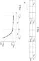
- the electronic control unit 22 there is stored a matrix M, which provides the compensation factor k as a function of the value of the supercharging pressure in the intake pipe 6 detected by the sensor 23.
- the matrix M contains two rows, each comprising a number N of boxes, each box univocally identifying the compensation factor k to be used for a given value of the supercharging pressure.
- the lower and upper limit values of the supercharging pressure are considered, indicated with P MIN and P MAX .
- the lower limit value of the supercharging pressure amounts to 600mbar and the upper limit value of the supercharging pressure amounts to 3000 mbar.
- the low-pressure circuit EGR LP is forcedly closed by acting upon the EGR valve 27, which adjusts the flow rate of the exhaust gases flowing through the bypass pipe 26, so that the mass M EGR_LP of exhaust gases recirculated through the low-pressure circuit EGR LP , which flows through the intake pipe 6, is equal to zero.
- the only thing flowing through the intake pipe 6 is the mass M AIR of fresh air coming from the outside.
- the value of the supercharging pressure must be constant for a time interval ⁇ t with a predetermined duration.
- the electronic control unit 22 is designed to recognize when the following condition occurs dP / ⁇ t ⁇ S 1
- auxiliary stability conditions can be added to the one described above and concerning the value of the supercharging pressure to be met to acquire the values of the compensation factor k; in particular, it is possible to impose a condition in which the speed n of the internal combustion engine 1 and/or the intake efficiency ⁇ SP (i.e. the ratio between the mass of air actually introduced and trapped in the cylinder 3 and the reference mass, namely the mass of air filling the single cylinder 3 in reference conditions) and/or the flow rate M AIR of fresh air coming from the outside that flows through the intake pipe 6 (detected by the air flow meter 7*) are kept constant for a time interval ⁇ t with a predetermined duration.
- ⁇ SP the ratio between the mass of air actually introduced and trapped in the cylinder 3 and the reference mass, namely the mass of air filling the single cylinder 3 in reference conditions
- the electronic control unit 22 is designed to recognize when one or more of the following conditions occur: dn / ⁇ t ⁇ S 2 d ⁇ SP / ⁇ t ⁇ S 3 dM AIR / ⁇ t ⁇ S 4
- the electronic control unit 22 has made sure that the conditions imposed by [11] - [14] are met, in order to acquire the values of the compensation factor k, it is further necessary to close the canister, so as to avoid the feeding of fuel that might tamper with the learning of the compensation factor k; in particular, it is necessary for the canister to be kept closed for a time interval with a predetermined duration, so as to be able to proceed with the acquisition of the values of the compensation factor k.
- the electronic control unit 22 is designed to enable the strategy of initialization of the matrix M and acquisition of the values of the compensation factor k only when the internal combustion engine 1 is in stable conditions, i.e. when there is a constant value of the supercharging pressure P of the internal combustion engine 1.
- the percentage O 2 of oxygen contained in the volume of the gas mixture flowing through the intake pipe 6 is detected by means of the sensor 30. Since the mass M EGR_LP of exhaust gases recirculated through the low-pressure circuit EGR LP , which flows through the intake pipe 6, is equal to zero (i.e. the only thing flowing through the intake pipe 6 is the mass M AIR of fresh air coming from the outside), the percentage O 2 of oxygen contained in the volume of the gas mixture flowing through the intake pipe 6, which is detected by means of the sensor 30, should be approximately equal to the percentage O 2_REF of oxygen contained in the volume of fresh air coming from the outside that flows through the intake pipe 6, which is determined by means of the air flow meter 7*.
- the value of the compensation factor k(P) for the supercharging pressure P is filtered by means of a filter, for example a first-order, low-pass filter.
- the values of the supercharging pressure P of the internal combustion engine 1 and of the corresponding compensation factor k(P) for the supercharging pressure P are stored in the matrix M.
- the control unit 22 is designed to enable the strategy of acquisition of the values of the compensation factor k every time the internal combustion engine 1 is in stable conditions, i.e. when there is a constant value of the supercharging pressure P of the internal combustion engine 1.
- the electronic control unit 22 In case the conditions imposed by [16] and [17] are met, the electronic control unit 22 is designed to store in the matrix M the new values of the supercharging pressure P of the internal combustion engine 1 and of the corresponding compensation factor k(P) for the supercharging pressure P. If, on the other hand, the comparison produces a negative result and, therefore, one of the conditions or both conditions imposed by [16] and [17] are not met, the electronic control unit 22 is designed to ignore the new values of the supercharging pressure P of the internal combustion engine 1 and of the corresponding compensation factor k(P) for the supercharging pressure P, so as not to store them in the matrix M.
- the compensation factor k(P) as a function of the supercharging pressure P has a development like the one shown in figure 2 .
- the development of the compensation factor k(P) as a function of the supercharging pressure P is substantially parabolic in a first portion (corresponding to the small values of the supercharging pressure P) up to a critical value of the supercharging pressure P*, which identifies a "knee" in the development of the compensation factor k(P) as a function of the supercharging pressure P, beyond which there is a second portion (corresponding to the great values of the supercharging pressure p), where the compensation factor k(P) as a function of the supercharging pressure P has a linear and almost constant development.
- the learned values of the compensation factor k(P) as a function of the supercharging pressure P should have a distribution s(P) that is variable as a function of the supercharging pressure P.
- the compensation facto k(P) as a function of the supercharging pressure P has a substantially parabolic development, it is advisable to store in the matrix M a large number of values distributed in the first portion.
- the compensation facto k(P) as a function of the supercharging pressure P has an almost constant development, it is sufficient to store in the matrix M a smaller number of values distributed in the second portion.
- the threshold values S 6 , S 7 must also fulfil the following conditions: S 6 ⁇ P ⁇ ⁇ P MIN / min s P + ⁇ 1 for P MIN ⁇ P ⁇ P ⁇ S 7 ⁇ P MAX ⁇ P ⁇ / min s P + ⁇ 2 for P ⁇ ⁇ P ⁇ P MAX
- the number N 1 of values of the compensation factor k as a function of the supercharging pressure P learned in the first portion is greater than the number N 2 of values of the compensation factor k as a function of the supercharging pressure P learned in the second portion.
- the matrix M has been filled ans stored in the electronic control unit 22 and this corresponds to the end of the step of initialization and learning of the values of the compensation factor k as a function of the supercharging pressure P.
- the pressure values comprised between the upper learned value P MAX_C of the supercharging pressure and the upper limit value P MAX of the supercharging pressure and the pressure values comprised, on the other hand, between the lower limit value P MIN of the supercharging pressure and the lower learned value P MIN_C of the supercharging pressure are extrapolated in a linear manner as described above, without being stored in the electronic control unit 22.
- the low-pressure circuit EGR LP is opened.
- the electronic control unit 22 is designed so that, at the end of the step of initialization and learning of the values of the compensation factor k as a function of the supercharging pressure P, both the mass M AIR of fresh air coming from the outside and the mass M EGR_LP of exhaust gases recirculated through the low-pressure circuit EGR LP flow through the intake pipe 6.
- stable conditions In order to acquire the values of the compensation factor k, stable conditions must occur; in particular, the value of the supercharging pressure must be constant for a time interval ⁇ t with a predetermined duration.
- the control unit 22 is designed to recognize when the conditions imposed by [11] - [14] are fulfilled and, at the same time, the mass M EGR_LP of exhaust gases recirculated through the low-pressure circuit EGR LP is equal to zero, i.e. when the low-pressure circuit is closed, without having imposed it, but based on the management in the engine point taken into account.
- the electronic control unit 22 is designed to compare the value of the supercharging pressure P with the difference between the lower learned value P MIN_C of the supercharging pressure and a tolerance value ⁇ P MIN (determined in a preliminary set up phase and stored in the electronic control unit 22, for example equal to 50 mbar).
- a tolerance value ⁇ P MIN (determined in a preliminary set up phase and stored in the electronic control unit 22, for example equal to 50 mbar).
- the values of the supercharging pressure P of the internal combustion engine and of the corresponding compensation factor k(P) for the supercharging pressure P are stored in the matrix M.
- the electronic control unit 22 is designed to disable the possibility of learning further compensation factors k(P) as a function of the supercharging pressure P for values of the supercharging pressure P that are smaller than the lower learned value P MIN_C of the supercharging pressure.
- the electronic control unit 22 is designed to compare the value of the supercharging pressure P with the difference between the upper learned value P MAX_C of the supercharging pressure and a tolerance value ⁇ P MAX (determined in a preliminary set up phase and stored in the electronic control unit 22, for example equal to 100 mbar).
- a tolerance value ⁇ P MAX (determined in a preliminary set up phase and stored in the electronic control unit 22, for example equal to 100 mbar).
- the values of the supercharging pressure P of the internal combustion engine 1 and of the corresponding compensation factor k(P) for the supercharging pressure P are stored in the matrix M.
- the electronic control unit 22 is designed to disable the possibility of learning further compensation factors k(P) as a function of the supercharging pressure P for values of the supercharging pressure P that are greater than the lower learned value P MAX_C of the supercharging pressure.
- the electronic control unit 22 is designed to determine the value of the compensation factor k for a given supercharging pressure P' non included in the matrix M by means of a linear interpolation of the two values of the compensation factor k that correspond to the two values of supercharging pressure P that are the closest to the supercharging pressure P'.
- the electronic control unit 22 is designed to determine the compensation factor k as a function of the supercharging pressure P' through a linear interpolation of the factor K relating to a pair of already learned values of the supercharging pressure P.
- an interpolation function k(P) is determined, which is obtained starting from the values stored in the matrix M and provides the compensation factor k as a function of the supercharging pressure P.
- the interpolation function k(P) is determined so as to minimize the standard deviation of the values of the compensation factor k learned and stored in the matrix M.
- the electronic control unit 22 is designed to determine the value of the compensation factor k for a given supercharging pressure P' included in the matrix M by means of the interpolation function k(P), which is obtained starting from the values stored in the matrix M.
- the canister does not need any longer to be kept closed in order to avoid the feeding of fuel that might tamper with the learning of the compensation factor k; in particular, the electronic control unit 22, once the acquisition of the values of the compensation factor k has ended, is designed to allow the canister to be opened so as to enable the feeding of fuel.
- the total mass flow rate M TOT_SD of the gas mixture flowing through the intake pipe 6 is calculated by means of a model.
- the low-pressure circuit EGR LP is limited, so that the mass M EGR_LP of exhaust gases recirculated through the low-pressure circuit EGR LP , which flows through the intake pipe 6, is smaller than a limit value M EGR_LP_MAX , which is variable as a function of the speed n and of the volume intake efficiency ⁇ SP of the internal combustion engine 1.
- the value of the supercharging pressure must be constant for a time interval ⁇ t with a predetermined duration.
- the electronic control unit 22 is designed to enable the strategy of acquisition of the values of the compensation factor k only when the internal combustion engine 1 is in stable conditions, i.e.
- the electronic control unit 22 is designed to determine the compensation factor k during the normal operation of the internal combustion engine 1, namely to initialize the values of the compensation factor k as a function of the supercharging pressure P in the matrix M during the normal operation of the internal combustion engine 1, as provided for in the description above.
- the factor k(P, M TOT ) is variable as a function both of the supercharging pressure P and of the total mass M TOT of the gas mixture flowing through the intake pipe 6 and hitting the sensor 30.
- the electronic control unit 22 is designed to determine the compensation factor k, i.e. to initialize the values of the compensation factor k as a function both of the supercharging pressure P and of the total mass M TOT of the gas mixture flowing through the intake pipe 6 and hitting the sensor 30 in the matrix M during the normal operation of the internal combustion engine 1, as provided for in the description above.
- the factor k(x 1 , x 2 , ... x n ) is variable as a function of a plurality of parameters comprising the supercharging pressure P, the total mass M TOT of the gas mixture flowing through the intake pipe 6 and hitting the sensor 30, the speed of the gas mixture flowing through the intake pipe 6 and hitting the sensor 30, the percentage of carbon dioxide in the gas mixture flowing through the intake pipe 6 and hitting the sensor 30, the percentage of steam (or absolute humidity) in the gas mixture flowing through the intake pipe 6 and hitting the sensor 30, and - finally - the temperature of the wall on which the sensor 30 is mounted.
- the electronic control unit 22 is designed to determine the compensation factor k, i.e. to initialize the values of the compensation factor k as a function of the plurality of parameters (comprising the supercharging pressure P, the total mass M TOT of the gas mixture flowing through the intake pipe 6 and hitting the sensor 30, the psychometric level PSI AIR_IN of the mass M AIR of fresh air coming from the outside that flows through the intake pipe 6, etc.) in the matrix M during the normal operation of the internal combustion engine 1, as provided for in the description above.
- the time needed for the initialization of the matrix M becomes significantly longer as the number of parameters being considered increases.
- the electronic control unit 22 is designed to recognize whether all the following conditions are fulfilled at the same time: dP / ⁇ t ⁇ S 1 dn / ⁇ t ⁇ S 2 d ⁇ SP / ⁇ t ⁇ S 3 dM AIR / ⁇ t ⁇ S 4 dM TOT / ⁇ t ⁇ S 10 d ⁇ S / ⁇ t ⁇ S 11 d ⁇ / ⁇ t ⁇ S 12
- the electronic control unit 22 is designed to enable the strategy of acquisition of the offset OF and of the values of the compensation factor k only when the internal combustion engine 1 is in stable conditions, i.e.
- the low-pressure circuit EGR LP is forcedly closed so that the mass M EGR_LP of exhaust gases recirculated through the low-pressure circuit EGR LP , which flows through the intake pipe 6, is equal to zero.
- the mass M AIR of fresh air coming from the outside is equal to the mass M AIR of fresh air coming from the outside.
- the low-pressure circuit EGR LP is limited so that the mass M EGR_LP of exhaust gases recirculated through the low-pressure circuit EGR LP , which flows through the intake pipe 6, is smaller than a limit value M EGR_LP_MAX , which is variable as a function of the speed n of the internal combustion engine 1 and of the volumetric efficiency ⁇ SP .
- the electronic control unit 22 is designed to correct the learned values of the compensation factor k, in particular close to the lower learned value P MIN_C of the supercharging pressure and the upper learned value P MAX_C of the supercharging pressure.
- the electronic control unit 22 is designed to determine a corrective factor k AGE , which is used in the matrix M for the correction of the learned compensation factors k.
- auxiliary stability conditions can be added to the one described above and concerning the value of the supercharging pressure to be met to acquire the values of the corrective factor k AGE ; in particular, it is possible to impose a condition in which the values are learned only if the speed n of the internal combustion engine 1 and/or the intake efficiency ⁇ SP (i.e.
- the electronic control unit 22 is designed to recognize when one or more of the conditions [12] - [14] occur.
- the electronic control unit 22 has made sure that the conditions imposed by [11] - [14] are met, in order to acquire the values of the corrective factor k AGE , it is further necessary to close the canister, so as to avoid the feeding of fuel that might tamper with the learning of the corrective factor k AGE ; in particular, it is necessary for the canister to be kept closed for a time interval with a predetermined duration, so as to be able to proceed with the acquisition of the values of the corrective factor k AGE .
- the low-pressure circuit EGR LP must be forcedly closed by acting upon the EGR valve 27, which adjusts the flow rate of the exhaust gases flowing through the bypass pipe 26, so that the mass M EGR_LP of exhaust gases recirculated through the low-pressure circuit EGR LP , which flows through the intake pipe 6, is equal to zero.
- the mass M AIR of fresh air coming from the outside is equal to zero.
- the corrective factor k AGE is calculated for at least two values P MIN_AGE , P MAX_AGE of the supercharging pressure, which must fulfil the following conditions: P MIN_C ⁇ P MIN_AGE ⁇ P MIN_C + ⁇ MIN P MAX_C ⁇ ⁇ MAX ⁇ P MAX_AGE ⁇ P MAX_C
- the electronic control unit 22 is designed to calculate an overall corrective factor K TOT as a function both of the compensation factor k and of the corrective factor K AGE .
- R EGR 1 ⁇ O 2 * k TOT P / O 2 _REF
- R EGR 1 ⁇ O 2 _TOT / O 2 _REF
- the electronic control unit 22 is designed to determine the compensation factor k during the normal operation of the internal combustion engine 1, namely to initialize the values of the compensation factor k as a function of the supercharging pressure P in the matrix M during the normal operation of the internal combustion engine 1, as provided for in the description above, once the value of the offset OF has been established.
- the learning strategy described in the description above is repeated at substantially regular intervals, after the internal combustion engine 1 has covered a given number of km.
- the methods to determine the mass flow rate R EGR of the low-pressure exhaust gas recirculation circuit EGR LP described above have the advantage of ensuring good performances both in terms of precision and in terms of reliability in time.
Landscapes
- Engineering & Computer Science (AREA)
- Chemical & Material Sciences (AREA)
- Combustion & Propulsion (AREA)
- Mechanical Engineering (AREA)
- General Engineering & Computer Science (AREA)
- Combined Controls Of Internal Combustion Engines (AREA)
- Exhaust-Gas Circulating Devices (AREA)
Claims (28)
- Verfahren zum Bestimmen des Massenstroms eines Niederdruck-Abgasrückführungskreislaufs, Niederdruck-EGR-Kreislaufs, (EGRLP) eines aufgeladenen Verbrennungsmotors (1), umfassend einen Ansaugkrümmer (4), der ein Gasgemisch durch ein Ansaugrohr (6) aufnimmt, und einen Turbolader (12), der mit einer Turbine (13) und einem entlang des Ansaugrohrs (6) angeordneten Lader (14) versehen ist; wobei der Niederdruck-Abgasrückführungskreislauf, Niederdruck-EGR-Kreislauf, (EGRLP) ein Bypassrohr (26), das von einem Abgaskanal (10) stromabwärts der Turbine (13) ausgeht und mit dem Ansaugrohr (6) stromaufwärts des Turboladers (14) verbunden ist, und ein EGR-Ventil (27) umfasst; der aufgeladene Verbrennungsmotor (1) des Weiteren eine elektronische Steuereinheit (22) und einen ersten Sensor (30), der dazu eingerichtet ist, die Menge an Sauerstoff zu messen, die in dem durch das Ansaugrohr (6) strömenden Gasgemisch verfügbar ist; und einen zweiten Sensor (23) zum Messen der Temperatur und des Drucks des in einem Ansaugkrümmer (4) vorhandenen Gasgemischs umfasst; wobei das Verfahren die Schritte umfasst:Erfassen des Prozentsatzes (O2) von Sauerstoff, der im Volumen des durch das Ansaugrohr (6) strömenden Gasgemischs enthalten ist, mittels des ersten Sensors (30);Steuern des aufgeladenen Verbrennungsmotors (1), um den Massenstrom eines Niederdruck-Abgasrückführungskreislaufs, Niederdruck-EGR-Kreislaufs, (EGRLP) auf null zu reduzieren;Bestimmen des Prozentsatzes (O2_REF) von Sauerstoff, der im Frischluftvolumen enthalten ist, das von außen durch das Ansaugrohr (6) strömt, durch die Formel O2_REF=f(PSIAIR_IN,TAIR_IN) ([7]); undBestimmen eines Kompensationsfaktors (k), wobei der Kompensationsfaktor (k) in Abhängigkeit vom Ladedruck (P) in dem Ansaugrohr (6) variabel ist und aus dem Verhältnis zwischen dem Prozentsatz (O2_REF) von Sauerstoff, der im Frischluftvolumen enthalten ist, das von außen durch das Ansaugrohr (6) strömt, und dem Prozentsatz (O2) von Sauerstoff, der im Volumen des durch das Ansaugrohr (6) strömenden Gasgemischs enthalten ist und mittels des ersten Sensors (30) erfasst wird, berechnet wird;Steuern des aufgeladenen Verbrennungsmotors (1), um einen Massenstrom ungleich null eines Niederdruck-Abgasrückführungskreislaufs, Niederdruck-EGR-Kreislaufs, (EGRLP) zuzuführen, sobald eine bestimmte Anzahl von Kompensationsfaktoren (k) gelernt ist; undBestimmen des Massenstroms des Niederdruck-Abgasrückführungskreislaufs, Niederdruck-EGR-Kreislaufs, (EGRLP) in Abhängigkeit des Kompensationsfaktors (k) durch die Formel REGR=1-(k*O2/O2_REF) ([7]).
- Verfahren nach Anspruch 1 und umfassend den weiteren Schritt des Bestimmens des prozentualen Massenstroms (%REGR) des Niederdruck-Abgasrückführungskreislaufs, Niederdruck-EGR-Kreislaufs, (EGRLP) im durch das Ansaugrohr (6) strömenden Gasgemisch durch die Formel:
 %REGR prozentualer Massenstrom des Niederdruck-Abgasrückführungskreislaufs, Niederdruck-EGR-Kreislaufs, (EGRLP) im durch das Ansaugrohr (6) strömenden Gasgemisch;O2 Prozentsatz von Sauerstoff, der im Volumen des durch das Ansaugrohr (6) strömenden Gasgemischs enthalten ist und mittels des ersten Sensors (30) erfasst wird; undO2_REF Prozentsatz von Sauerstoff, der im von Frischluftvolumen enthalten ist, das von außen durch das Ansaugrohr (6) strömt.
 - Verfahren nach Anspruch 1 oder 2 und umfassend den weiteren Schritt des Bestimmens des Prozentsatzes (O2_REF) von Sauerstoff, der im Frischluftvolumen enthalten ist, das von außen durch das Ansaugrohr (6) strömt, in Abhängigkeit des psychometrischen Niveaus (PSIAIR_IN), der Temperatur (TAIR_IN) der Masse (MAIR) der Frischluft, die von außen durch das Ansaugrohr (6) strömt, und des Drucks (PAIR_IN) der Masse (MAIR) von Frischluft, die von außen durch das Ansaugrohr (6) strömt.
- Verfahren nach Anspruch 2 oder 3 und umfassend den weiteren Schritt des Bestimmens des prozentualen Massenstroms (%REGR) des Niederdruck-Abgasrückführungskreislaufs, Niederdruck-EGR-Kreislaufs, (EGRLP) in Abhängigkeit des Produkts zwischen dem Kompensationsfaktor (k) und dem Prozentsatz (O2) von Sauerstoff, der im Volumen des durch das Ansaugrohr (6) strömenden Gasgemischs enthalten ist und mittels des ersten Sensors (30) erfasst wird.
- Verfahren nach einem der vorhergehenden Ansprüche, wobei der Schritt des Bestimmens des Kompensationsfaktors (k) nur unter stabilen Bedingungen des aufgeladenen Verbrennungsmotors (1), insbesondere des Ladedrucks (P) in dem Ansaugrohr (6), durchgeführt wird.
- Verfahren nach einem der vorhergehenden Ansprüche und umfassend den weiteren Schritt des Speicherns der Werte der Menge (P, MTOT) und der entsprechenden Kompensationsfaktoren (k) in einer Matrix (M).
- Verfahren nach Anspruch 6, wobei jeder Wert der Menge (P, MTOT) und der entsprechende Kompensationsfaktor (k), die in der Matrix (M) gespeichert sind, die Bedingungen erfüllen:

 P aktueller Wert der Menge (P, MTOT), die untersucht wird;Pi-1 Pi+1 angrenzende Werte der Menge (P, MTOT), bereits in der Matrix (M) gespeichert; undS5 erster Schwellenwert.
 - Verfahren nach Anspruch 7, wobei der Schwellenwert (Ss) in Abhängigkeit der Menge (P, MTOT) variabel ist.
- Verfahren nach einem der Ansprüche 6 bis 8 und umfassend die weiteren Schritte desBestimmens eines kritischen Werts (P*) der Menge (P, MTOT) im Trend des Kompensationsfaktors k(P);Bestimmens eines unteren Grenzwerts (PMIN) der Menge (P, MTOT) und eines oberen Grenzwerts (PMAX) der Menge (P, MTOT); undSpeicherns der Werte der Menge (P, MTOT) und der entsprechenden Kompensationsfaktoren (k) in der Matrix (M), bis die folgenden Bedingungen erfüllt sind:



 P Menge (P, MTOT);P* kritischer Wert der Menge (P, MTOT) im Trend des Kompensationsfaktors k(P);N1, N2 Anzahl gelernter Werte des Kompensationsfaktors (k);PMIN unterer Grenzwert der Menge (P, MTOT);PMAX oberer Grenzwert der Menge (P, MTOT);PMIN_C unterer gelernter Wert der Menge (P, MTOT), in der Matrix (M) gespeichert;PMAX_C oberer gelernter Wert der Menge (P, MTOT), in der Matrix (M) gespeichert; undS6, S7, S8, S9 Schwellenwerte.
 - Verfahren nach Anspruch 9, wobei der zweite und der dritte Wert (S6, S7) die folgenden Bedingungen erfüllen:

 S6, S7 Schwellenwerte;Δ1, Δ2 Anpassungsspielraum;P* kritischer Wert der Menge (P, MTOT) im Trend des Kompensationsfaktors k(P);PMIN unterer Grenzwert der Menge (P, MTOT);PMAX oberer Grenzwert (PMAX) der Menge (P, MTOT);s(P) Verteilung der gelernten Werte des Kompensationsfaktors k(P) innerhalb der Matrix (M), die in Abhängigkeit der Menge (P, MTOT) variabel ist.
 - Verfahren nach Anspruch 9 oder 10 und umfassend den weiteren Schritt des Speicherns der Werte der Menge (P, MTOT) und der entsprechenden Kompensationsfaktoren (k) in der Matrix (M), die mittels der folgenden Formeln berechnet werden:
k(P) = ((k(PMAX_C) - k(PMAX_C-1))/ (PMAX_C - PMAX_C-1)) * gMAX * (P - PMAX_C) + k(PMAX_C) [22] k(P) = ((k(PMIN_C+1) - k(PMIN_C))/ (PMIN_C+1 - PMIN_C)) * gMIN * (PMIN_C - P) + k(PMIN_C) [23] PMAX_C oberer Wert des Ladedrucks, in der Matrix (M) gespeichert;PMAX_C-1 Wert des in der Matrix (M) gespeicherten Ladedrucks vor dem oberen Wert des in der Matrix (M) gespeicherten Ladedrucks;P aktueller Ladedruck;gMAX Korrekturkoeffizient, der in einer vorläufigen Einrichtungsphase ermittelt und gespeichert wird;PMIN_C unterer gelernter Wert des Ladedrucks, in der Matrix (M) gespeichert;PMIN_C_+1 gelernter Wert des in der Matrix (M) gespeicherten Ladedrucks, der auf den unteren gelernten Wert des in der Matrix (M) gespeicherten Ladedrucks folgt;gMIN Korrekturkoeffizient, der in einer vorläufigen Einrichtungsphase ermittelt und gespeichert wird. - Verfahren nach einem der Ansprüche 6 bis 11 und umfassend den weiteren Schritt des Bestimmens, während des normalen Betriebs des aufgeladenen Verbrennungsmotors (1), der Kompensationsfaktoren (k) in Abhängigkeit der Menge (P, MTOT) durch eine Interpolation der in der Matrix (M) gespeicherten gelernten Werte des Kompensationsfaktors k(P).
- Verfahren nach einem der vorhergehenden Ansprüche und umfassend die weiteren Schritte des:Bestimmens eines Versatzes (OF), vorzugsweise eines konstanten, um den Prozentsatz (O2) von Sauerstoff, der im Volumen des durch das Ansaugrohr (6) strömenden Gasgemischs enthalten ist und mittels des ersten Sensors (30) erfasst wird, zu bestimmen; undBestimmens des Massenstroms des Niederdruck-Abgasrückführungskreislaufs, Niederdruck-EGR-Kreislaufs, (EGRLP) in Abhängigkeit des Versatzes (OF).
- Verfahren nach Anspruch 13 und umfassend die weiteren Schritte des:Erfassens des Prozentsatzes (O2) von Sauerstoff, der im Volumen des durch das Ansaugrohr (6) strömenden Gasgemischs enthalten ist, mittels des ersten Sensors (30);Bestimmens des Versatzes (OF) durch die Lösung des folgenden Gleichungssystems

 O2_EST Prozentsatz von Sauerstoff, der im von außen kommenden Frischluftvolumen enthalten ist und mittels eines "Speed Density"-Modells und des Stroms eines Luftmengenmessers (7*), der dazu eingerichtet ist, die Masse des von dem Verbrennungsmotor (1) angesaugten Frischluftstroms zu erfassen, geschätzt wird;O2 Prozentsatz von Sauerstoff, der im Volumen des durch das Ansaugrohr (6) strömenden Gasgemischs enthalten ist und mittels des ersten Sensors (30) erfasst wird;k (P) Kompensationsfaktor; undO2_REF Prozentsatz von Sauerstoff, der im Frischluftvolumen enthalten ist, das von außen durch das Ansaugrohr (6) strömt.
 - Verfahren nach einem der vorhergehenden Ansprüche und umfassend die weiteren Schritte des:Bestimmens eines Gesamtkorrekturfaktors (kTOT) in Abhängigkeit des Kompensationsfaktors (k); wobei der Gesamtkorrekturfaktor (kTOT) mittels des Verhältnisses des Kompensationsfaktors (k) und eines Korrekturfaktors (kAGE) erhalten wird; undBestimmens des prozentualen Massenstroms (%REGR) des Niederdruck-Abgasrückführungskreislaufs, Niederdruck-EGR-Kreislaufs, (EGRLP) in Abhängigkeit des Gesamtkorrekturfaktors (kTOT).
- Verfahren nach Anspruch 15 und umfassend den weiteren Schritt des Berechnens des Korrekturfaktors (kAGE) für mindestens ein Paar signifikanter Werte (PMIN_AGE ,PMAX_AGE) der Menge (P, MTOT) mittels folgender Formel:
 O2 Prozentsatz von Sauerstoff, der im Volumen des durch das Ansaugrohr (6) strömenden Gasgemischs enthalten ist und mittels des ersten Sensors (30) erfasst wird;O2_REF Prozentsatz von Sauerstoff, der im Frischluftvolumen enthalten ist, das von außen durch das Ansaugrohr (6) strömt;k Kompensationsfaktor in Abhängigkeit der Menge (P, MTOT);PMIN_C unterer gelernter Wert der Menge (P, MTOT);PMAX_C oberer gelernter Wert der Menge (P, MTOT);PMIN_AGE unterer signifikanter Wert der Menge (P, MTOT);PMAX_AGE oberer signifikanter Wert der Menge (P, MTOT);ΔMIN ΔMAX Mengen, die den Bereich der Intervalle definieren, in denen der Korrekturfaktor (kAGE) berechnet werden soll.
 - Verfahren nach Anspruch 16 und umfassend den weiteren Schritt des Bestimmens der Korrekturfaktoren (kAGE) durch eine Interpolation der gelernten Werte des Korrekturfaktors (kAGE) für das Paar signifikanter Werte (PMIN_AGE, PMAX_AGE) der Menge (P, MTOT).
- Verfahren nach einem der Ansprüche 15 bis 17 und umfassend die weiteren Schritte des:Bestimmens eines Versatzes (OF), vorzugsweise eines konstanten, um den Prozentsatz (O2) von Sauerstoff, der im Volumen des durch das Ansaugrohr (6) strömenden Gasgemischs enthalten ist und mittels des ersten Sensors (30) erfasst wird, zu bestimmen; undBestimmens des Massenstroms des Niederdruck-Abgasrückführungskreislaufs, Niederdruck-EGR-Kreislaufs, (EGRLP) in Abhängigkeit des Versatzes (OF).
- Verfahren nach Anspruch 18 und umfassend die weiteren Schritte des:Erfassens des Prozentsatzes (O2) von Sauerstoff, der im Volumen des durch das Ansaugrohr (6) strömenden Gasgemischs enthalten ist, mittels des ersten Sensors (30);Bestimmens des Versatzes (OF) durch die Lösung des folgenden Gleichungssystems

 O2_FST Prozentsatz von Sauerstoff, der im von außen kommenden Frischluftvolumen enthalten ist und mittels eines "Speed Density"-Modells und des Stroms eines Luftmengenmessers (7*), der dazu eingerichtet ist, die Masse des von dem Verbrennungsmotor (1) angesaugten Frischluftstroms zu erfassen, geschätzt wird;O2 Prozentsatz von Sauerstoff, der im Volumen des durch das Ansaugrohr (6) strömenden Gasgemischs enthalten ist und mittels des ersten Sensors (30) erfasst wird;kTOT Gesamtkorrekturfaktor in Abhängigkeit der Menge (P, MTOT); undO2_REF Prozentsatz von Sauerstoff, der im Frischluftvolumen enthalten ist, das von außen durch das Ansaugrohr (6) strömt.
 - Verfahren nach einem der Ansprüche 7 bis 19, wobei der Niederdruck-Abgasrückführungskreislauf, Niederdruck-EGR-Kreislauf, (EGRLP) zwangsweise geschlossen wird, sodass der Massenstrom des Niederdruck-Abgasrückführungskreislaufs, Niederdruck-EGR-Kreislaufs, (EGRLP), der durch das Ansaugrohr (6) strömt, gleich null ist, um die Initialisierung der Matrix (M) zu ermöglichen.
- Verfahren nach Anspruch 20 und umfassend den weiteren Schritt des Erkennens, wenn eine oder mehrere der folgenden Bedingungen eintreten, um die Initialisierung der Matrix (M) zu ermöglichen:


 dn Variation der Drehzahl (n) des Verbrennungsmotors (1);dηSP Variation des volumetrischen Wirkungsgrads;dMAIR Variation der Masse der von außen kommenden Frischluft, die durch das Ansaugrohr (6) strömt;Δt Zeitintervall mit einer vorgegebenen Dauer undS2, S3, S4 Schwellenwerte, die vorzugsweise in einer vorläufigen Einrichtungsphase bestimmt werden.
 - Verfahren nach Anspruch 21 und umfassend die weiteren Schritte des:Erkennens, wenn der Massenstrom (EGRLP) des Niederdruck-Abgasrückführungskreislaufs, Niederdruck-EGR-Kreislaufs, (EGRLP), der durch das Ansaugrohr (6) strömt, gleich null ist und gleichzeitig der Kraftstoffstrom gleich null ist; undSpeicherns der Werte der Menge (P, MTOT) und der entsprechenden Kompensationsfaktoren (k) in der Matrix (M) in Übereinstimmung mit Werten der Menge (P, MTOT), die kleiner als der untere gelernte Wert (PMIN_C) sind, und mit Werten der Menge (P, MTOT), die größer als der obere gelernte Wert (PMAX_C) sind.
- Verfahren nach Anspruch 22 und umfassend die weiteren Schritte des:Vergleichens des Werts der Menge (P, MTOT) mit der Differenz zwischen dem unteren gelernten Wert (PMIN_C) und einem Toleranzwert (ΔPMIN) undSpeicherns des Werts der Menge (P, MTOT) und des entsprechenden Kompensationsfaktors (k) in der Matrix (M), falls der Wert der Menge (P, MTOT) kleiner oder gleich der Differenz zwischen dem unteren gelernten Wert (PMIN_C) und dem Toleranzwert (ΔPMIN) ist.
- Verfahren nach Anspruch 22 oder 23 und umfassend die weiteren Schritte des:Vergleichens des Werts der Menge (P, MTOT) mit der Differenz zwischen dem oberen gelernten Wert (PMAX_C) und einem Toleranzwert (ΔPMAX) undSpeicherns des Werts der Menge (P, MTOT) und des entsprechenden Kompensationsfaktors (k) in der Matrix (M), falls der Wert der Menge (P, MTOT) größer oder gleich der Differenz zwischen dem oberen gelernten Wert (PMAX_C) und einem Toleranzwert (ΔPMAX) ist.
- Verfahren nach einem der Ansprüche 20 bis 24 und umfassend den weiteren Schritt des Schließens einer Kraftstoffdampfsammelrampe, um den Durchgang von Kraftstoff zu verhindern und so die Initialisierung der Matrix (M) zu ermöglichen.
- Verfahren nach einem der Ansprüche 20 bis 25 und umfassend den weiteren Schritt des Öffnens des Niederdruck-Abgasrückführungskreislaufs, Niederdruck-EGR-Kreislaufs, (EGRLP) nach der Initialisierung der Matrix (M), sodass der Massenstrom des Niederdruck-Abgasrückführungskreislaufs, Niederdruck-EGR-Kreislaufs, (EGRLP), der durch das Ansaugrohr (6) strömt, größer als null ist.
- Verfahren nach Anspruch 25 und umfassend den weiteren Schritt des Zulassens des Durchgangs von Kraftstoff, sobald die Matrix (M) initialisiert wurde.
- Verfahren nach einem der vorhergehenden Ansprüche und umfassend den weiteren Schritt des Neuinitialisierens des Kompensationsfaktors (k) und/oder des Korrekturfaktors (kAGE) in im Wesentlichen regelmäßigen Intervallen und insbesondere nach einer bestimmten Kilometerzahl des aufgeladenen Verbrennungsmotors (1).
Applications Claiming Priority (1)
| Application Number | Priority Date | Filing Date | Title |
|---|---|---|---|
| ITBO20140687 | 2014-12-09 |
Publications (2)
| Publication Number | Publication Date |
|---|---|
| EP3040541A1 EP3040541A1 (de) | 2016-07-06 |
| EP3040541B1 true EP3040541B1 (de) | 2025-06-04 |
Family
ID=52727207
Family Applications (1)
| Application Number | Title | Priority Date | Filing Date |
|---|---|---|---|
| EP15198775.7A Active EP3040541B1 (de) | 2014-12-09 | 2015-12-09 | Verfahren zur bestimmung des massedurchflusses eines niederdruck-abgasrückführungskreislaufs eines aufgeladenen verbrennungsmotors |
Country Status (1)
| Country | Link |
|---|---|
| EP (1) | EP3040541B1 (de) |
Families Citing this family (4)
| Publication number | Priority date | Publication date | Assignee | Title |
|---|---|---|---|---|
| IT201800009537A1 (it) | 2018-10-17 | 2020-04-17 | Magneti Marelli Spa | Metodo di stima per determinare la concentrazione di gas di scarico ricircolato presente in un cilindro di un motore a combustione interna |
| US11739701B2 (en) * | 2018-11-08 | 2023-08-29 | Marelli Europe S.P.A. | Method to determine the mass of air trapped in each cylinder of an internal combustion engine |
| IT201900004879A1 (it) * | 2019-04-01 | 2020-10-01 | Magneti Marelli Spa | Metodo per il controllo della combustione di un motore a combustione interna |
| IT201900004875A1 (it) * | 2019-04-01 | 2020-10-01 | Magneti Marelli Spa | Metodo per il controllo della combustione di un motore a combustione interna |
Family Cites Families (4)
| Publication number | Priority date | Publication date | Assignee | Title |
|---|---|---|---|---|
| JP4380754B2 (ja) | 2007-09-21 | 2009-12-09 | トヨタ自動車株式会社 | 内燃機関の排気還流装置 |
| CN101688483B (zh) * | 2008-05-20 | 2012-04-18 | 丰田自动车株式会社 | 内燃机的排气回流装置 |
| GB2475316B (en) * | 2009-11-16 | 2016-03-16 | Gm Global Tech Operations Inc | Method for controlling the level of oxygen in the intake manifold of an internal combustion engine equipped with a low pressure EGR system |
| US20130268176A1 (en) | 2012-04-05 | 2013-10-10 | GM Global Technology Operations LLC | Exhaust gas recirculation control systems and methods for low engine delta pressure conditions |
-
2015
- 2015-12-09 EP EP15198775.7A patent/EP3040541B1/de active Active
Also Published As
| Publication number | Publication date |
|---|---|
| EP3040541A1 (de) | 2016-07-06 |
Similar Documents
| Publication | Publication Date | Title |
|---|---|---|
| US9976503B2 (en) | Method for estimating charge air cooler condensation storage and/or release with an intake oxygen sensor | |
| US8073638B2 (en) | Method for determining the ignitability of fuel with an unknown fuel quality | |
| EP2198141B1 (de) | Abgasrückführungsvorrichtung und verfahren zur kalkulation der abgasrückführungsflussrate für einen verbrennungsmotor | |
| US8527186B2 (en) | Method and apparatus for adaptive feedback control of an excess air ratio in a compression ignition natural gas engine | |
| US8387593B2 (en) | EGR flow rate control apparatus of internal combustion engine | |
| EP3040541B1 (de) | Verfahren zur bestimmung des massedurchflusses eines niederdruck-abgasrückführungskreislaufs eines aufgeladenen verbrennungsmotors | |
| EP3029307B1 (de) | Steuerungsvorrichtung für verbrennungsmotor | |
| RU2692871C2 (ru) | Система и способ (варианты) для двигателя | |
| EP2518291A1 (de) | Steuervorrichtung für einen Verbrennungsmotor | |
| US10330034B2 (en) | Device and method for predicting the exhaust gas recirculation rate | |
| US20130239669A1 (en) | Estimation device for cylinder intake air amount in an internal combustion engine | |
| US20150114367A1 (en) | Internal combustion engine control apparatus | |
| CN106103955B (zh) | 发动机系统的异常判定装置 | |
| JP2013036355A (ja) | 空気流量センサ校正装置 | |
| EP2565430A1 (de) | Steuervorrichtung für einen verbrennungsmotor | |
| US9567886B2 (en) | Method to control the temperature of the exhaust gases of a supercharged internal combustion engine | |
| EP3128159B1 (de) | Verfahren zur steuerung einer agr-schaltung zur niederdruck-abgasrückführung in einem verbrennungsmotor | |
| US9309822B2 (en) | Method for operating an internal combustion engine, control element, internal combustion engine | |
| US10677183B2 (en) | Internal combustion engine control apparatus | |
| JP6625837B2 (ja) | Egr制御方法及びegr装置 | |
| EP2772627A1 (de) | Kraftstoffeigenschaftenerkennungssystem für ein fahrzeug | |
| EP3128158B1 (de) | Verfahren zur steuerung eines niederdruckabgasrückführungskreislaufes in einem verbrennungsmotor | |
| JP2015102006A (ja) | 吸入空気量推定装置 |
Legal Events
| Date | Code | Title | Description |
|---|---|---|---|
| PUAI | Public reference made under article 153(3) epc to a published international application that has entered the european phase |
Free format text: ORIGINAL CODE: 0009012 |
|
| AK | Designated contracting states |
Kind code of ref document: A1 Designated state(s): AL AT BE BG CH CY CZ DE DK EE ES FI FR GB GR HR HU IE IS IT LI LT LU LV MC MK MT NL NO PL PT RO RS SE SI SK SM TR |
|
| AX | Request for extension of the european patent |
Extension state: BA ME |
|
| STAA | Information on the status of an ep patent application or granted ep patent |
Free format text: STATUS: REQUEST FOR EXAMINATION WAS MADE |
|
| 17P | Request for examination filed |
Effective date: 20170104 |
|
| STAA | Information on the status of an ep patent application or granted ep patent |
Free format text: STATUS: EXAMINATION IS IN PROGRESS |
|
| 17Q | First examination report despatched |
Effective date: 20210415 |
|
| RAP3 | Party data changed (applicant data changed or rights of an application transferred) |
Owner name: MARELLI EUROPE S.P.A. |
|
| GRAP | Despatch of communication of intention to grant a patent |
Free format text: ORIGINAL CODE: EPIDOSNIGR1 |
|
| STAA | Information on the status of an ep patent application or granted ep patent |
Free format text: STATUS: GRANT OF PATENT IS INTENDED |
|
| RIC1 | Information provided on ipc code assigned before grant |
Ipc: F02D 41/24 20060101ALI20241029BHEP Ipc: F02D 41/18 20060101ALI20241029BHEP Ipc: F02D 41/14 20060101ALI20241029BHEP Ipc: F02D 41/00 20060101AFI20241029BHEP |
|
| GRAJ | Information related to disapproval of communication of intention to grant by the applicant or resumption of examination proceedings by the epo deleted |
Free format text: ORIGINAL CODE: EPIDOSDIGR1 |
|
| STAA | Information on the status of an ep patent application or granted ep patent |
Free format text: STATUS: EXAMINATION IS IN PROGRESS |
|
| INTG | Intention to grant announced |
Effective date: 20241119 |
|
| INTC | Intention to grant announced (deleted) | ||
| GRAP | Despatch of communication of intention to grant a patent |
Free format text: ORIGINAL CODE: EPIDOSNIGR1 |
|
| STAA | Information on the status of an ep patent application or granted ep patent |
Free format text: STATUS: GRANT OF PATENT IS INTENDED |
|
| INTG | Intention to grant announced |
Effective date: 20250120 |
|
| GRAS | Grant fee paid |
Free format text: ORIGINAL CODE: EPIDOSNIGR3 |
|
| GRAA | (expected) grant |
Free format text: ORIGINAL CODE: 0009210 |
|
| STAA | Information on the status of an ep patent application or granted ep patent |
Free format text: STATUS: THE PATENT HAS BEEN GRANTED |
|
| P01 | Opt-out of the competence of the unified patent court (upc) registered |
Free format text: CASE NUMBER: APP_15627/2025 Effective date: 20250331 |
|
| AK | Designated contracting states |
Kind code of ref document: B1 Designated state(s): AL AT BE BG CH CY CZ DE DK EE ES FI FR GB GR HR HU IE IS IT LI LT LU LV MC MK MT NL NO PL PT RO RS SE SI SK SM TR |
|
| REG | Reference to a national code |
Ref country code: GB Ref legal event code: FG4D |
|
| REG | Reference to a national code |
Ref country code: CH Ref legal event code: EP |
|
| REG | Reference to a national code |
Ref country code: DE Ref legal event code: R096 Ref document number: 602015091765 Country of ref document: DE |
|
| REG | Reference to a national code |
Ref country code: IE Ref legal event code: FG4D |
|
| REG | Reference to a national code |
Ref country code: NL Ref legal event code: MP Effective date: 20250604 |
|
| PG25 | Lapsed in a contracting state [announced via postgrant information from national office to epo] |
Ref country code: FI Free format text: LAPSE BECAUSE OF FAILURE TO SUBMIT A TRANSLATION OF THE DESCRIPTION OR TO PAY THE FEE WITHIN THE PRESCRIBED TIME-LIMIT Effective date: 20250604 Ref country code: ES Free format text: LAPSE BECAUSE OF FAILURE TO SUBMIT A TRANSLATION OF THE DESCRIPTION OR TO PAY THE FEE WITHIN THE PRESCRIBED TIME-LIMIT Effective date: 20250604 |
|
| REG | Reference to a national code |
Ref country code: LT Ref legal event code: MG9D |
|
| PG25 | Lapsed in a contracting state [announced via postgrant information from national office to epo] |
Ref country code: NO Free format text: LAPSE BECAUSE OF FAILURE TO SUBMIT A TRANSLATION OF THE DESCRIPTION OR TO PAY THE FEE WITHIN THE PRESCRIBED TIME-LIMIT Effective date: 20250904 Ref country code: GR Free format text: LAPSE BECAUSE OF FAILURE TO SUBMIT A TRANSLATION OF THE DESCRIPTION OR TO PAY THE FEE WITHIN THE PRESCRIBED TIME-LIMIT Effective date: 20250905 |
|
| PG25 | Lapsed in a contracting state [announced via postgrant information from national office to epo] |
Ref country code: PL Free format text: LAPSE BECAUSE OF FAILURE TO SUBMIT A TRANSLATION OF THE DESCRIPTION OR TO PAY THE FEE WITHIN THE PRESCRIBED TIME-LIMIT Effective date: 20250604 |
|
| PG25 | Lapsed in a contracting state [announced via postgrant information from national office to epo] |
Ref country code: BG Free format text: LAPSE BECAUSE OF FAILURE TO SUBMIT A TRANSLATION OF THE DESCRIPTION OR TO PAY THE FEE WITHIN THE PRESCRIBED TIME-LIMIT Effective date: 20250604 |
|
| PG25 | Lapsed in a contracting state [announced via postgrant information from national office to epo] |
Ref country code: HR Free format text: LAPSE BECAUSE OF FAILURE TO SUBMIT A TRANSLATION OF THE DESCRIPTION OR TO PAY THE FEE WITHIN THE PRESCRIBED TIME-LIMIT Effective date: 20250604 |
|
| PG25 | Lapsed in a contracting state [announced via postgrant information from national office to epo] |
Ref country code: RS Free format text: LAPSE BECAUSE OF FAILURE TO SUBMIT A TRANSLATION OF THE DESCRIPTION OR TO PAY THE FEE WITHIN THE PRESCRIBED TIME-LIMIT Effective date: 20250904 |
|
| PG25 | Lapsed in a contracting state [announced via postgrant information from national office to epo] |
Ref country code: LV Free format text: LAPSE BECAUSE OF FAILURE TO SUBMIT A TRANSLATION OF THE DESCRIPTION OR TO PAY THE FEE WITHIN THE PRESCRIBED TIME-LIMIT Effective date: 20250604 |
|
| PG25 | Lapsed in a contracting state [announced via postgrant information from national office to epo] |
Ref country code: NL Free format text: LAPSE BECAUSE OF FAILURE TO SUBMIT A TRANSLATION OF THE DESCRIPTION OR TO PAY THE FEE WITHIN THE PRESCRIBED TIME-LIMIT Effective date: 20250604 |
|
| PG25 | Lapsed in a contracting state [announced via postgrant information from national office to epo] |
Ref country code: PT Free format text: LAPSE BECAUSE OF FAILURE TO SUBMIT A TRANSLATION OF THE DESCRIPTION OR TO PAY THE FEE WITHIN THE PRESCRIBED TIME-LIMIT Effective date: 20251006 |
|
| REG | Reference to a national code |
Ref country code: AT Ref legal event code: MK05 Ref document number: 1800522 Country of ref document: AT Kind code of ref document: T Effective date: 20250604 |
|
| PG25 | Lapsed in a contracting state [announced via postgrant information from national office to epo] |
Ref country code: IS Free format text: LAPSE BECAUSE OF FAILURE TO SUBMIT A TRANSLATION OF THE DESCRIPTION OR TO PAY THE FEE WITHIN THE PRESCRIBED TIME-LIMIT Effective date: 20251004 |
|
| PGFP | Annual fee paid to national office [announced via postgrant information from national office to epo] |
Ref country code: DE Payment date: 20251126 Year of fee payment: 11 |
|
| PG25 | Lapsed in a contracting state [announced via postgrant information from national office to epo] |
Ref country code: SM Free format text: LAPSE BECAUSE OF FAILURE TO SUBMIT A TRANSLATION OF THE DESCRIPTION OR TO PAY THE FEE WITHIN THE PRESCRIBED TIME-LIMIT Effective date: 20250604 Ref country code: AT Free format text: LAPSE BECAUSE OF FAILURE TO SUBMIT A TRANSLATION OF THE DESCRIPTION OR TO PAY THE FEE WITHIN THE PRESCRIBED TIME-LIMIT Effective date: 20250604 |
|
| PGFP | Annual fee paid to national office [announced via postgrant information from national office to epo] |
Ref country code: IT Payment date: 20251119 Year of fee payment: 11 |
|
| PGFP | Annual fee paid to national office [announced via postgrant information from national office to epo] |
Ref country code: FR Payment date: 20251119 Year of fee payment: 11 |
|
| PG25 | Lapsed in a contracting state [announced via postgrant information from national office to epo] |
Ref country code: CZ Free format text: LAPSE BECAUSE OF FAILURE TO SUBMIT A TRANSLATION OF THE DESCRIPTION OR TO PAY THE FEE WITHIN THE PRESCRIBED TIME-LIMIT Effective date: 20250604 |
|
| PG25 | Lapsed in a contracting state [announced via postgrant information from national office to epo] |
Ref country code: EE Free format text: LAPSE BECAUSE OF FAILURE TO SUBMIT A TRANSLATION OF THE DESCRIPTION OR TO PAY THE FEE WITHIN THE PRESCRIBED TIME-LIMIT Effective date: 20250604 |
|
| PG25 | Lapsed in a contracting state [announced via postgrant information from national office to epo] |
Ref country code: SK Free format text: LAPSE BECAUSE OF FAILURE TO SUBMIT A TRANSLATION OF THE DESCRIPTION OR TO PAY THE FEE WITHIN THE PRESCRIBED TIME-LIMIT Effective date: 20250604 Ref country code: RO Free format text: LAPSE BECAUSE OF FAILURE TO SUBMIT A TRANSLATION OF THE DESCRIPTION OR TO PAY THE FEE WITHIN THE PRESCRIBED TIME-LIMIT Effective date: 20250604 |
|
| REG | Reference to a national code |
Ref country code: DE Ref legal event code: R097 Ref document number: 602015091765 Country of ref document: DE |
|
| PLBE | No opposition filed within time limit |
Free format text: ORIGINAL CODE: 0009261 |
|
| STAA | Information on the status of an ep patent application or granted ep patent |
Free format text: STATUS: NO OPPOSITION FILED WITHIN TIME LIMIT |
|
| PG25 | Lapsed in a contracting state [announced via postgrant information from national office to epo] |
Ref country code: DK Free format text: LAPSE BECAUSE OF FAILURE TO SUBMIT A TRANSLATION OF THE DESCRIPTION OR TO PAY THE FEE WITHIN THE PRESCRIBED TIME-LIMIT Effective date: 20250604 |
|
| REG | Reference to a national code |
Ref country code: CH Ref legal event code: L10 Free format text: ST27 STATUS EVENT CODE: U-0-0-L10-L00 (AS PROVIDED BY THE NATIONAL OFFICE) Effective date: 20260416 |