EP3040549A1 - Kanalgeführter haubenträger für einen gasturbinenmotor - Google Patents
Kanalgeführter haubenträger für einen gasturbinenmotor Download PDFInfo
- Publication number
- EP3040549A1 EP3040549A1 EP15200690.4A EP15200690A EP3040549A1 EP 3040549 A1 EP3040549 A1 EP 3040549A1 EP 15200690 A EP15200690 A EP 15200690A EP 3040549 A1 EP3040549 A1 EP 3040549A1
- Authority
- EP
- European Patent Office
- Prior art keywords
- ducted
- cowl support
- annular
- cowl
- support
- Prior art date
- Legal status (The legal status is an assumption and is not a legal conclusion. Google has not performed a legal analysis and makes no representation as to the accuracy of the status listed.)
- Withdrawn
Links
- 230000002093 peripheral effect Effects 0.000 claims description 13
- 239000002131 composite material Substances 0.000 claims description 5
- 239000003570 air Substances 0.000 description 17
- 239000007789 gas Substances 0.000 description 6
- 238000000034 method Methods 0.000 description 4
- 238000001816 cooling Methods 0.000 description 3
- 239000000463 material Substances 0.000 description 3
- 238000011144 upstream manufacturing Methods 0.000 description 3
- 230000000740 bleeding effect Effects 0.000 description 2
- 238000004891 communication Methods 0.000 description 2
- 230000001276 controlling effect Effects 0.000 description 2
- 230000009970 fire resistant effect Effects 0.000 description 2
- 239000012530 fluid Substances 0.000 description 2
- 229920000049 Carbon (fiber) Polymers 0.000 description 1
- 239000004593 Epoxy Substances 0.000 description 1
- 230000001154 acute effect Effects 0.000 description 1
- 239000012080 ambient air Substances 0.000 description 1
- 238000005219 brazing Methods 0.000 description 1
- 239000004917 carbon fiber Substances 0.000 description 1
- 239000000567 combustion gas Substances 0.000 description 1
- 238000010276 construction Methods 0.000 description 1
- 238000005516 engineering process Methods 0.000 description 1
- 239000000446 fuel Substances 0.000 description 1
- 239000011159 matrix material Substances 0.000 description 1
- 229910001092 metal group alloy Inorganic materials 0.000 description 1
- 239000007769 metal material Substances 0.000 description 1
- 238000004806 packaging method and process Methods 0.000 description 1
- 230000035515 penetration Effects 0.000 description 1
- 230000001105 regulatory effect Effects 0.000 description 1
- 238000003466 welding Methods 0.000 description 1
Images

Classifications
-
- F—MECHANICAL ENGINEERING; LIGHTING; HEATING; WEAPONS; BLASTING
- F01—MACHINES OR ENGINES IN GENERAL; ENGINE PLANTS IN GENERAL; STEAM ENGINES
- F01D—NON-POSITIVE DISPLACEMENT MACHINES OR ENGINES, e.g. STEAM TURBINES
- F01D25/00—Component parts, details, or accessories, not provided for in, or of interest apart from, other groups
- F01D25/28—Supporting or mounting arrangements, e.g. for turbine casing
-
- F—MECHANICAL ENGINEERING; LIGHTING; HEATING; WEAPONS; BLASTING
- F02—COMBUSTION ENGINES; HOT-GAS OR COMBUSTION-PRODUCT ENGINE PLANTS
- F02C—GAS-TURBINE PLANTS; AIR INTAKES FOR JET-PROPULSION PLANTS; CONTROLLING FUEL SUPPLY IN AIR-BREATHING JET-PROPULSION PLANTS
- F02C7/00—Features, components parts, details or accessories, not provided for in, or of interest apart form groups F02C1/00 - F02C6/00; Air intakes for jet-propulsion plants
- F02C7/32—Arrangement, mounting, or driving, of auxiliaries
-
- F—MECHANICAL ENGINEERING; LIGHTING; HEATING; WEAPONS; BLASTING
- F02—COMBUSTION ENGINES; HOT-GAS OR COMBUSTION-PRODUCT ENGINE PLANTS
- F02K—JET-PROPULSION PLANTS
- F02K3/00—Plants including a gas turbine driving a compressor or a ducted fan
- F02K3/02—Plants including a gas turbine driving a compressor or a ducted fan in which part of the working fluid by-passes the turbine and combustion chamber
- F02K3/04—Plants including a gas turbine driving a compressor or a ducted fan in which part of the working fluid by-passes the turbine and combustion chamber the plant including ducted fans, i.e. fans with high volume, low pressure outputs, for augmenting the jet thrust, e.g. of double-flow type
- F02K3/075—Plants including a gas turbine driving a compressor or a ducted fan in which part of the working fluid by-passes the turbine and combustion chamber the plant including ducted fans, i.e. fans with high volume, low pressure outputs, for augmenting the jet thrust, e.g. of double-flow type controlling flow ratio between flows
-
- F—MECHANICAL ENGINEERING; LIGHTING; HEATING; WEAPONS; BLASTING
- F02—COMBUSTION ENGINES; HOT-GAS OR COMBUSTION-PRODUCT ENGINE PLANTS
- F02C—GAS-TURBINE PLANTS; AIR INTAKES FOR JET-PROPULSION PLANTS; CONTROLLING FUEL SUPPLY IN AIR-BREATHING JET-PROPULSION PLANTS
- F02C3/00—Gas-turbine plants characterised by the use of combustion products as the working fluid
- F02C3/04—Gas-turbine plants characterised by the use of combustion products as the working fluid having a turbine driving a compressor
- F02C3/13—Gas-turbine plants characterised by the use of combustion products as the working fluid having a turbine driving a compressor having variable working fluid interconnections between turbines or compressors or stages of different rotors
-
- F—MECHANICAL ENGINEERING; LIGHTING; HEATING; WEAPONS; BLASTING
- F05—INDEXING SCHEMES RELATING TO ENGINES OR PUMPS IN VARIOUS SUBCLASSES OF CLASSES F01-F04
- F05D—INDEXING SCHEME FOR ASPECTS RELATING TO NON-POSITIVE-DISPLACEMENT MACHINES OR ENGINES, GAS-TURBINES OR JET-PROPULSION PLANTS
- F05D2220/00—Application
- F05D2220/30—Application in turbines
- F05D2220/32—Application in turbines in gas turbines
-
- F—MECHANICAL ENGINEERING; LIGHTING; HEATING; WEAPONS; BLASTING
- F05—INDEXING SCHEMES RELATING TO ENGINES OR PUMPS IN VARIOUS SUBCLASSES OF CLASSES F01-F04
- F05D—INDEXING SCHEME FOR ASPECTS RELATING TO NON-POSITIVE-DISPLACEMENT MACHINES OR ENGINES, GAS-TURBINES OR JET-PROPULSION PLANTS
- F05D2230/00—Manufacture
- F05D2230/50—Building or constructing in particular ways
- F05D2230/53—Building or constructing in particular ways by integrally manufacturing a component, e.g. by milling from a billet or one piece construction
-
- F—MECHANICAL ENGINEERING; LIGHTING; HEATING; WEAPONS; BLASTING
- F05—INDEXING SCHEMES RELATING TO ENGINES OR PUMPS IN VARIOUS SUBCLASSES OF CLASSES F01-F04
- F05D—INDEXING SCHEME FOR ASPECTS RELATING TO NON-POSITIVE-DISPLACEMENT MACHINES OR ENGINES, GAS-TURBINES OR JET-PROPULSION PLANTS
- F05D2240/00—Components
- F05D2240/10—Stators
- F05D2240/14—Casings or housings protecting or supporting assemblies within
-
- F—MECHANICAL ENGINEERING; LIGHTING; HEATING; WEAPONS; BLASTING
- F05—INDEXING SCHEMES RELATING TO ENGINES OR PUMPS IN VARIOUS SUBCLASSES OF CLASSES F01-F04
- F05D—INDEXING SCHEME FOR ASPECTS RELATING TO NON-POSITIVE-DISPLACEMENT MACHINES OR ENGINES, GAS-TURBINES OR JET-PROPULSION PLANTS
- F05D2260/00—Function
- F05D2260/30—Retaining components in desired mutual position
Definitions
- This invention relates generally to stationary structures in gas turbine engines, and more particularly to support frames in such engines.
- a typical turbofan engine includes in serial flow communication a fan, a low pressure compressor or “booster”, a high pressure compressor (“HPC”), a combustor, a high pressure turbine (“HPT”), and a low pressure turbine (“LPT”), with the HPT driving the HPC, and the LPT driving both the fan and the booster.
- HPC high pressure compressor
- HPT high pressure turbine
- LPT low pressure turbine
- the rotating components of a gas turbine engine are supported by bearings mounted in one or more structural frames.
- the frames typically take the form of an inner hub connected to an outer casing by an array of radially extending airfoil-shaped struts.
- Typical turbofan engines have a fan hub frame ("FHF”) just aft of the fan.
- FHF fan hub frame
- VBV variable bleed valve
- the VBV system includes one or more bleed valves mounted within the fan hub frame.
- the valves are open during low power operation of the engine, such as at idle, for bleeding a portion of the compressed air.
- the bleed valves are closed at high power operation of the engine, such as during cruise or takeoff, since bleeding is no longer required.
- air is passed from the booster flowpath through the fan hub frame and into a bypass duct.
- the fan hub frame area includes, in addition to the fan hub frame itself, numerous attached components such as separate VBV ducts to direct the bypass flow, fire-resistant fire blankets to protect the fan hub frame, and cowl supports. While effective, these structures increase the weight, complexity, and cost of the engine.
- a ducted cowl support includes an annular structure configured to be mounted to an annular turbine engine frame and including one or more bypass ducts integrally formed therein.
- Figure 1 depicts a schematic, partially-sectioned view of an exemplary gas turbine engine 10 having a longitudinal, axial centerline axis 12.
- the term “axial” or “longitudinal” refers to a direction parallel to the centerline axis 12 described above, while “radial” refers to a direction perpendicular to the axial direction, and “tangential” or “circumferential” refers to a direction mutually perpendicular to the axial and tangential directions.
- the terms “forward” or “front” refer to a location relatively upstream in an air flow passing through or around a component
- the terms “aft” or “rear” refer to a location relatively downstream in an air flow passing through or around a component. The direction of this flow is shown by the arrow 26 in FIG. 1 .
- the engine 10 includes in serial flow communication a fan 14, a low pressure compressor or "booster" 16, a high pressure compressor 18, a combustor 20, a high pressure turbine 22, and a low pressure turbine 24 all disposed coaxially about the centerline axis 12.
- a fan 14 a low pressure compressor or "booster” 16
- a high pressure compressor 18, a combustor 20, a high pressure turbine 22, and a low pressure turbine 24 all disposed coaxially about the centerline axis 12.
- Collectively the HPC 18, combustor 20, and HPT 22 are referred to as a "gas generator” or "core”.
- the fan 14, booster 16, and low pressure turbine 24 are referred to as a "low pressure system”.
- the high pressure turbine 22 conventionally drives the high pressure compressor 18, and the low pressure turbine 24 conventionally drives both the fan 14 and the booster 16.
- the core and low pressure systems are operable in a known manner to generate a primary or core flow as well as a fan flow or bypass flow. While the illustrated engine 10 is a high-bypass turbofan engine, the principles described herein are equally applicable to other types of turbine engines that include stationary frames
- the fan 14 receives ambient air 26 and initially pressurizes it to form pressurized fan air 28.
- the fan 14 is disposed upstream of an annular fan bypass duct 30 through which is channeled an outer portion of the fan air 28, with an inner portion of the fan air 28 being channeled into the booster 16.
- the bypass duct 30 includes radially spaced apart outer and inner annular walls 30a and 30b, respectively.
- the inner wall 30b is defined by a core cowl 31 which surrounds the core.
- the fan air channeled into the booster 16 is further compressed therein for forming compressed air 32 which is further channeled from the booster 16 and through an annular compressor core duct 34 disposed downstream from the booster 16 and upstream of the high pressure compressor 18.
- the core duct 34 includes radially outer and inner annular walls 34a and 34b, respectively.
- the compressed air 32 is further compressed in the high pressure compressor 18 and is then channeled to the combustor 20 wherein it is conventionally mixed with fuel and ignited for generating combustion gases 36 which are channeled through the high pressure turbine 22 and the low pressure turbine 24 which extract energy therefrom.
- the high pressure turbine 22 is disposed directly downstream from the combustor 20.
- the low pressure turbine 24 is disposed directly downstream of the high pressure turbine 22 and immediately downstream of the compressors 16 and 18 and may include a passive blade-tip clearance control system 40 provided with cooling airflow.
- the clearance control system 40 itself is of a known type and includes one or more annular tubes 40a surrounding the low pressure turbine 24 for impinging cooling air on the conventional shrouds surrounding the blade tips for controlling the clearances therebetween during operation of the engine 10.
- the system 40 receives cooling air through a feed pipe 42 which communicates with the booster flowpath.
- the core duct 34 includes a plurality of variable bleed valves 44 in its outer wall 34a disposed between the booster 16 and the high pressure compressor 18. Means (not shown) such as an actuator are provided for selectively positioning the bleed valve 44 in open or closed positions.
- the engine 10 includes an annular fan hub frame 46 disposed axially between the booster 16 and the high pressure compressor 18. It is an annular structure with forward and aft faces 48 and 50, respectively, and an annular array of fan struts 52 extend radially outward therefrom to the outer wall 30a of the bypass duct 30.
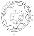
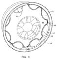
- a cowl support 54 is mounted to the aft end of the fan hub frame 46. As assembled, the cowl support 54 is a complete annular structure. It may be manufactured as a single 360-degree ring, as shown in FIG. 2 , or it may comprise two or more arcuate segments which are assembled to form a complete annulus, as shown in FIG. 3 .
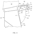
- the cowl support 54 has a forward end 56 which abuts the aft face 50 of the fan hub frame 46, and an aft end 58.
- the structure of the cowl support 54 includes a peripheral wall 60 which is generally cylindrical or frustoconical and which is relatively thin compared to the overall diameter of the cowl support 54.
- the peripheral wall 60 incorporates an annular array of integral or unitary bypass ducts 62 formed therein.
- each bypass duct 62 defines a convex bulge (viewed aft looking forward) which, when disposed abutting the fan hub frame 46, forms an air flow passageway.
- the fan hub frame 46 includes a plurality of openings 47 formed around its periphery. Each opening 47 mates with one of the bypass ducts 62).
- the bypass ducts 62 may be simply-curved (i.e. part-tubular) or compound-curved (i.e. part spherical).
- One or more of the bypass ducts 62 may include an integral clearance control take-off duct 64, which is coupled to the feed pipe 42 shown in FIG. 1 .
- a generally radially-oriented forward flange 66 is disposed at the forward end 56 of the cowl support 54. Its path spans the spaces between the bypass ducts 62, and follows the inner edge 68 of each bypass duct 62.
- the forward flange 66 includes a plurality of spaced-apart flange holes which may accept fasteners 70 such as rivets, screws, or bolts to secure the cowl support 54 to the fan hub frame 46.
- An annular, generally frustoconical aft skirt 72 extends radially outward from the peripheral wall 60, near the aft end 58 of the cowl support 54.
- a generally axially-oriented annular aft flange 74 is disposed at the distal end 76 of the aft skirt 72 and includes a plurality of spaced-apart flange holes which may accept fasteners 78 such as rivets, screws, or bolts.
- the cowl support 54 may be constructed from a suitable material which is rigid and fire-resistant.
- suitable materials include metal alloys or composite materials, such as an epoxy matrix with carbon fibers embedded therein.
- the cowl support 54 may be cast, forged, molded, machined from billet, or built up from individual components which are then bonded together, for example by welding or brazing.
- Collectively, the fan hub frame 46 and the cowl support 54 define a firewall, that is, their materials and configuration are selected to resist fire penetration according to relevant engineering or regulatory standards.
- V-groove flange 80 is disposed at the aft end 58 of the cowl support 54.
- the V-groove flange 80 includes a generally V-shaped, radially-outward-facing groove 82. It may be attached to the peripheral wall 60 with fasteners 84 such as rivets, screws, or bolts, so that it may be easily replaced when worn.
- the V-groove flange 80 may be constructed from metal or composite material as described above. Alternatively, the V-groove flange 80 may be of integral or unitary construction with the remainder of the cowl support 54.
- the core cowl 31 described above has a downturned flange 86 at its forward end, or other suitable connecting structure. This flange 86 is received in the V-shaped groove 82, forming a mechanical connection between the core cowl 31 and the cowl support 54.
- each of the bleed vents 88 includes a plurality of axially spaced apart louvers 90 inclined in a downstream direction for injecting bleed air from the bypass valves 44 at an acute angle downstream into the bypass duct 30 for reducing mixing losses with the fan air 28.
- the forward end of each bleed vent 88 is received in an annular groove 92 in the fan strut 52, and the aft end of each bleed vent 88 is coupled to the aft flange 74 of the cowl support 54 via the fasteners 78.
- the cowl support 54 is an integral, unitary, or monolithic structure that takes the place of prior art VBV bleed ducts and cowl support. It structurally supports the core cowl 31. It provides fluid connectivity from the booster flowpath to the bypass duct 30, provides a bleed point for clearance control air flow, and forms the firewall of the engine 10.
- the cowl support 53 combines the functionality of multiple existing parts as compared to prior art designs. It is expected to save significant weight, eliminate extraneous piece parts (including fire blankets), and to simplify packaging and assembly. Depending on the particular application, it may represent a cost reduction as compared to the prior art structures it replaces.
Landscapes
- Engineering & Computer Science (AREA)
- Chemical & Material Sciences (AREA)
- Combustion & Propulsion (AREA)
- Mechanical Engineering (AREA)
- General Engineering & Computer Science (AREA)
- Structures Of Non-Positive Displacement Pumps (AREA)
Applications Claiming Priority (2)
| Application Number | Priority Date | Filing Date | Title |
|---|---|---|---|
| US201462098878P | 2014-12-31 | 2014-12-31 | |
| US14/966,390 US10247043B2 (en) | 2014-12-31 | 2015-12-11 | Ducted cowl support for a gas turbine engine |
Publications (1)
| Publication Number | Publication Date |
|---|---|
| EP3040549A1 true EP3040549A1 (de) | 2016-07-06 |
Family
ID=55066345
Family Applications (1)
| Application Number | Title | Priority Date | Filing Date |
|---|---|---|---|
| EP15200690.4A Withdrawn EP3040549A1 (de) | 2014-12-31 | 2015-12-17 | Kanalgeführter haubenträger für einen gasturbinenmotor |
Country Status (6)
| Country | Link |
|---|---|
| US (1) | US10247043B2 (de) |
| EP (1) | EP3040549A1 (de) |
| JP (1) | JP2016125495A (de) |
| CN (1) | CN105736149B (de) |
| BR (1) | BR102015032777A2 (de) |
| CA (1) | CA2915747A1 (de) |
Cited By (1)
| Publication number | Priority date | Publication date | Assignee | Title |
|---|---|---|---|---|
| WO2018122538A1 (fr) * | 2016-12-30 | 2018-07-05 | Safran Aircraft Engines | Moyeu de carter intermédiaire comprenant des canaux de guidage du flux de décharge formés par les ailettes de décharge |
Families Citing this family (3)
| Publication number | Priority date | Publication date | Assignee | Title |
|---|---|---|---|---|
| EP2927433B1 (de) * | 2014-04-04 | 2018-09-26 | United Technologies Corporation | Aktive spaltkontrolle für einen gasturbinenmotor |
| US11300002B2 (en) | 2018-12-07 | 2022-04-12 | Pratt & Whitney Canada Corp. | Static take-off port |
| US11702995B2 (en) | 2020-07-15 | 2023-07-18 | Pratt & Whitney Canada Corp. | Devices and methods for guiding bleed air in a turbofan engine |
Citations (2)
| Publication number | Priority date | Publication date | Assignee | Title |
|---|---|---|---|---|
| US20080193279A1 (en) * | 2007-02-12 | 2008-08-14 | Snecma | Relief device for a turbojet and a turbojet comprising same |
| FR2961251A1 (fr) * | 2010-06-15 | 2011-12-16 | Snecma | Moyeu de carter intermediaire pour turboreacteur d'aeronef comprenant des moyens d'evacuation de debris ameliores |
Family Cites Families (10)
| Publication number | Priority date | Publication date | Assignee | Title |
|---|---|---|---|---|
| DE4340951A1 (de) | 1992-12-04 | 1994-06-09 | Grumman Aerospace Corp | Einstückiges Triebwerkeinlaß-Schallrohr |
| DE59404777D1 (de) | 1994-01-17 | 1998-01-22 | Siemens Ag | Verfahren und Vorrichtung zur Führung eines Prozesses |
| JP2002275613A (ja) | 2001-03-21 | 2002-09-25 | Nisshin Steel Co Ltd | めっき付着量制御方法及び制御システム |
| DE102004060425B3 (de) | 2004-08-24 | 2006-04-27 | Betriebsforschungsinstitut VDEh - Institut für angewandte Forschung GmbH | Verfahren zur Bandbeschichtung |
| US7094020B2 (en) | 2004-09-15 | 2006-08-22 | General Electric Company | Swirl-enhanced aerodynamic fastener shield for turbomachine |
| WO2006091138A1 (en) | 2005-02-25 | 2006-08-31 | Volvo Aero Corporation | A bleed structure for a bleed passage in a gas turbine engine |
| FR2913432B1 (fr) | 2007-03-07 | 2011-06-17 | Siemens Vai Metals Tech Sas | Procede et installation de depot en continu d'un revetement sur un support en bande |
| US8651809B2 (en) * | 2010-10-13 | 2014-02-18 | General Electric Company | Apparatus and method for aligning a turbine casing |
| GB201104043D0 (en) | 2011-03-10 | 2011-04-20 | Rolls Royce Plc | A gas turbine engine |
| US20120308369A1 (en) | 2011-05-31 | 2012-12-06 | Mra Systems, Inc. | Laminate thermal insulation blanket for aircraft applications and process therefor |
-
2015
- 2015-12-11 US US14/966,390 patent/US10247043B2/en active Active
- 2015-12-17 EP EP15200690.4A patent/EP3040549A1/de not_active Withdrawn
- 2015-12-18 CA CA2915747A patent/CA2915747A1/en not_active Abandoned
- 2015-12-24 JP JP2015250814A patent/JP2016125495A/ja active Pending
- 2015-12-29 BR BR102015032777A patent/BR102015032777A2/pt not_active Application Discontinuation
- 2015-12-31 CN CN201511014246.5A patent/CN105736149B/zh active Active
Patent Citations (2)
| Publication number | Priority date | Publication date | Assignee | Title |
|---|---|---|---|---|
| US20080193279A1 (en) * | 2007-02-12 | 2008-08-14 | Snecma | Relief device for a turbojet and a turbojet comprising same |
| FR2961251A1 (fr) * | 2010-06-15 | 2011-12-16 | Snecma | Moyeu de carter intermediaire pour turboreacteur d'aeronef comprenant des moyens d'evacuation de debris ameliores |
Cited By (3)
| Publication number | Priority date | Publication date | Assignee | Title |
|---|---|---|---|---|
| WO2018122538A1 (fr) * | 2016-12-30 | 2018-07-05 | Safran Aircraft Engines | Moyeu de carter intermédiaire comprenant des canaux de guidage du flux de décharge formés par les ailettes de décharge |
| FR3061519A1 (fr) * | 2016-12-30 | 2018-07-06 | Safran Aircraft Engines | Moyeu de carter intermediaire comprenant des canaux de guidage du flux de decharge formes par les ailettes de decharge |
| US11053846B2 (en) | 2016-12-30 | 2021-07-06 | Safran Aircraft Engines | Intermediate housing hub comprising discharge flow guiding channels formed by the discharge fins |
Also Published As
| Publication number | Publication date |
|---|---|
| US10247043B2 (en) | 2019-04-02 |
| CA2915747A1 (en) | 2016-06-30 |
| US20160186613A1 (en) | 2016-06-30 |
| JP2016125495A (ja) | 2016-07-11 |
| CN105736149A (zh) | 2016-07-06 |
| BR102015032777A2 (pt) | 2016-10-04 |
| CN105736149B (zh) | 2018-02-23 |
Similar Documents
| Publication | Publication Date | Title |
|---|---|---|
| EP2586990B1 (de) | Integriertes Gehäuse und Stator | |
| EP2794182B1 (de) | Stützstruktur für ein Gasturbinentriebwerk, zugehöriges Gasturbinentriebwerk, Flugzeug und Herstellungsverfahren | |
| US8240121B2 (en) | Retrofit dirt separator for gas turbine engine | |
| EP2333237B1 (de) | Bläser mit mehrstufigen Schaufeln an der Spitze | |
| US7739866B2 (en) | Turbofan case and method of making | |
| EP3118417A1 (de) | Ummantelungsanordnung für ein gasturbinentriebwerk | |
| US20110120083A1 (en) | Gas turbine engine with outer fans | |
| US11635030B2 (en) | Compressor bleed apparatus for a turbine engine | |
| US9784133B2 (en) | Turbine frame and airfoil for turbine frame | |
| US20200011203A1 (en) | Blade containment structure | |
| EP3066318B1 (de) | Innendiffusorgehäuse für einen gasturbinenmotor | |
| EP2366871B1 (de) | Verfahren und Vorrichtung für eine strukturelle Auslassleitschaufel | |
| US20090056125A1 (en) | Compressor impellers, compressor sections including the compressor impellers, and methods of manufacturing | |
| EP2971660B1 (de) | Thermische anpassung einer schallauskleidungskartusche für einen gasturbinenmotor | |
| US20150027130A1 (en) | Split ring valve | |
| US12535007B2 (en) | Cover plate connections for a hollow fan blade | |
| US10247043B2 (en) | Ducted cowl support for a gas turbine engine | |
| CN120100531A (zh) | 用于具有阻尼元件的发动机的开式风扇转子的可变节距翼型件组件 | |
| US12018575B2 (en) | Turbine engine with a cowl door | |
| US20200056496A1 (en) | Turbine-tip clearance control system offtake | |
| EP2623729B1 (de) | Gasturbinentriebwerk mit einem Gebläse und Booster-Anschlussstück und zugehöriges Verfahren | |
| US7329088B2 (en) | Pilot relief to reduce strut effects at pilot interface | |
| US10746034B2 (en) | Airfoil for a turbo machine | |
| US20200063604A1 (en) | Gas turbine engine | |
| US20140161605A1 (en) | Gas turbine structure |
Legal Events
| Date | Code | Title | Description |
|---|---|---|---|
| PUAI | Public reference made under article 153(3) epc to a published international application that has entered the european phase |
Free format text: ORIGINAL CODE: 0009012 |
|
| AK | Designated contracting states |
Kind code of ref document: A1 Designated state(s): AL AT BE BG CH CY CZ DE DK EE ES FI FR GB GR HR HU IE IS IT LI LT LU LV MC MK MT NL NO PL PT RO RS SE SI SK SM TR |
|
| AX | Request for extension of the european patent |
Extension state: BA ME |
|
| 17P | Request for examination filed |
Effective date: 20170109 |
|
| RBV | Designated contracting states (corrected) |
Designated state(s): AL AT BE BG CH CY CZ DE DK EE ES FI FR GB GR HR HU IE IS IT LI LT LU LV MC MK MT NL NO PL PT RO RS SE SI SK SM TR |
|
| STAA | Information on the status of an ep patent application or granted ep patent |
Free format text: STATUS: THE APPLICATION IS DEEMED TO BE WITHDRAWN |
|
| 18D | Application deemed to be withdrawn |
Effective date: 20180703 |