EP3040558B1 - Procédé de commande d'une pompe centrifuge à régulation de régime dans un système combiné refroidissement/chauffage et pompe centrifuge - Google Patents
Procédé de commande d'une pompe centrifuge à régulation de régime dans un système combiné refroidissement/chauffage et pompe centrifuge Download PDFInfo
- Publication number
- EP3040558B1 EP3040558B1 EP15003526.9A EP15003526A EP3040558B1 EP 3040558 B1 EP3040558 B1 EP 3040558B1 EP 15003526 A EP15003526 A EP 15003526A EP 3040558 B1 EP3040558 B1 EP 3040558B1
- Authority
- EP
- European Patent Office
- Prior art keywords
- temperature
- heating
- cooling
- mode
- rotary pump
- Prior art date
- Legal status (The legal status is an assumption and is not a legal conclusion. Google has not performed a legal analysis and makes no representation as to the accuracy of the status listed.)
- Active
Links
Images


Classifications
-
- F—MECHANICAL ENGINEERING; LIGHTING; HEATING; WEAPONS; BLASTING
- F04—POSITIVE - DISPLACEMENT MACHINES FOR LIQUIDS; PUMPS FOR LIQUIDS OR ELASTIC FLUIDS
- F04D—NON-POSITIVE-DISPLACEMENT PUMPS
- F04D15/00—Control, e.g. regulation, of pumps, pumping installations or systems
- F04D15/0066—Control, e.g. regulation, of pumps, pumping installations or systems by changing the speed, e.g. of the driving engine
-
- F—MECHANICAL ENGINEERING; LIGHTING; HEATING; WEAPONS; BLASTING
- F04—POSITIVE - DISPLACEMENT MACHINES FOR LIQUIDS; PUMPS FOR LIQUIDS OR ELASTIC FLUIDS
- F04D—NON-POSITIVE-DISPLACEMENT PUMPS
- F04D1/00—Radial-flow pumps, e.g. centrifugal pumps; Helico-centrifugal pumps
-
- F—MECHANICAL ENGINEERING; LIGHTING; HEATING; WEAPONS; BLASTING
- F24—HEATING; RANGES; VENTILATING
- F24D—DOMESTIC- OR SPACE-HEATING SYSTEMS, e.g. CENTRAL HEATING SYSTEMS; DOMESTIC HOT-WATER SUPPLY SYSTEMS; ELEMENTS OR COMPONENTS THEREFOR
- F24D3/00—Hot-water central heating systems
-
- F—MECHANICAL ENGINEERING; LIGHTING; HEATING; WEAPONS; BLASTING
- F05—INDEXING SCHEMES RELATING TO ENGINES OR PUMPS IN VARIOUS SUBCLASSES OF CLASSES F01-F04
- F05D—INDEXING SCHEME FOR ASPECTS RELATING TO NON-POSITIVE-DISPLACEMENT MACHINES OR ENGINES, GAS-TURBINES OR JET-PROPULSION PLANTS
- F05D2270/00—Control
- F05D2270/01—Purpose of the control system
- F05D2270/02—Purpose of the control system to control rotational speed (n)
-
- F—MECHANICAL ENGINEERING; LIGHTING; HEATING; WEAPONS; BLASTING
- F05—INDEXING SCHEMES RELATING TO ENGINES OR PUMPS IN VARIOUS SUBCLASSES OF CLASSES F01-F04
- F05D—INDEXING SCHEME FOR ASPECTS RELATING TO NON-POSITIVE-DISPLACEMENT MACHINES OR ENGINES, GAS-TURBINES OR JET-PROPULSION PLANTS
- F05D2270/00—Control
- F05D2270/30—Control parameters, e.g. input parameters
- F05D2270/303—Temperature
-
- F—MECHANICAL ENGINEERING; LIGHTING; HEATING; WEAPONS; BLASTING
- F24—HEATING; RANGES; VENTILATING
- F24D—DOMESTIC- OR SPACE-HEATING SYSTEMS, e.g. CENTRAL HEATING SYSTEMS; DOMESTIC HOT-WATER SUPPLY SYSTEMS; ELEMENTS OR COMPONENTS THEREFOR
- F24D2220/00—Components of central heating installations excluding heat sources
- F24D2220/02—Fluid distribution means
- F24D2220/0207—Pumps
-
- Y—GENERAL TAGGING OF NEW TECHNOLOGICAL DEVELOPMENTS; GENERAL TAGGING OF CROSS-SECTIONAL TECHNOLOGIES SPANNING OVER SEVERAL SECTIONS OF THE IPC; TECHNICAL SUBJECTS COVERED BY FORMER USPC CROSS-REFERENCE ART COLLECTIONS [XRACs] AND DIGESTS
- Y02—TECHNOLOGIES OR APPLICATIONS FOR MITIGATION OR ADAPTATION AGAINST CLIMATE CHANGE
- Y02B—CLIMATE CHANGE MITIGATION TECHNOLOGIES RELATED TO BUILDINGS, e.g. HOUSING, HOUSE APPLIANCES OR RELATED END-USER APPLICATIONS
- Y02B30/00—Energy efficient heating, ventilation or air conditioning [HVAC]
- Y02B30/70—Efficient control or regulation technologies, e.g. for control of refrigerant flow, motor or heating
Definitions
- the invention relates to a method for controlling a variable-speed centrifugal pump in a combined heating-cooling system, which can be operated in a heating mode and in a cooling mode and which comprises at least one consumer to which the centrifugal pump delivers a medium from a central heat or cold generator. Moreover, the invention relates to a centrifugal pump for such a combined heating-cooling system.
- a method of this type is known from the US application US 2009/319087 A1 known.
- the pump is operated at a first speed N1 and above the limit temperature at a second speed N2.
- the pump is operated above a certain limit temperature of the medium in cooling operation at a third rotational speed N1 'and below this limit temperature at a fourth rotational speed N2'.
- the speeds are calculated taking into account side conditions such as the outside temperature and the heat loss of the room, where the speeds N2, N2 'ensure a required minimum volume flow through the consumers and the speeds N1, N1' any speed between N2, N2 'and a rated speed are.
- Ceiling systems are known in which pipelines extend like a floor heating snake or circular through the ceiling of a room. The same is known for walls. These ceilings or walls form adjustable temperature control zones for heating or cooling the room. They convince by lower investment costs, since only a single transfer system has to be installed for heating and cooling. In addition, this transfer system is very efficient, since it can be used with very low system temperatures due to the large-area laid heating / cooling surfaces.
- the centrifugal pump which promotes the heating or cooling medium to the consumer or consumers, must always be adapted in terms of performance, so that the consumers are neither over-supplied nor under-supplied.
- the centrifugal pump is designed for a specific operating point, which is dependent on the desired temperature spread between flow and return. The centrifugal pump is adjusted so that its head and her Volumetric flow to ensure the desired temperature spread. In a centrifugal pump for a combined heating and cooling system, however, such a setting leads to conflicting interests, since different temperature spreads are required in heating and cooling operation.
- a cooling circuit for ceiling cooling may have a flow temperature of 16 ° C and a return temperature of 18 ° C, i. a spread of 2K. Therefore, different mass flows are needed. It is obvious that the centrifugal pump would have to be designed differently for the two operating cases. Because the volume flow for the heating mode is usually much smaller than the volume flow in cooling mode. However, since this is not possible, it is designed only for one operating mode, for example, for the cooling operation. For this purpose, a design mass flow is determined via the required cooling capacity and an assumed temperature spread. For the heating case, such a design is not made. This leads to the problem that for the heating case, the design spread usually adjusts so that sets the same design mass flow as in the cooling case. This means that the nominal delivery height is not changed and thus unnecessary pump energy is consumed.
- the core idea of the present application is to adapt the regulation of the centrifugal pump, in particular its delivery height, to the operating mode present in each case. This makes the centrifugal pump completely independent.
- electronics are integrated into the centrifugal pump, which carries out a determination and evaluation of the medium temperature with respect to the present operating mode, as well as controls the speed control by specifying a height adapted to the detected operating height depending on the result.
- the device for determining the temperature is a temperature sensor, which is in communication with the medium.
- the device can be completely or partially integrated in the centrifugal pump or arranged externally thereto.
- the supply electronics is part of the pump electronics and the actual measuring means is arranged outside the centrifugal pump.
- the measuring means may be arranged in the pump housing, the suction nozzle or the discharge nozzle.
- the heating operation may be concluded when the temperature of the medium exceeds an upper limit temperature. Because for the heating mode, the medium is heated to a certain temperature and then closed promoted to at least one consumer.
- the limit temperature may ideally be between 28 ° C and 42 ° C, in particular about 30 ° C.
- the cooling operation may suitably be concluded when the temperature of the medium falls below a lower limit temperature. Because for the Cooling operation, the medium is cooled down to a certain temperature and then promoted to the at least one consumer.
- the lower limit temperature may ideally be between 13 ° C and 17 ° C, especially about 15 ° C.
- the determined temperature is a local flow temperature of the at least one consumer.
- a return temperature can be used.
- the flow temperature has the advantage that the lower and upper limit temperatures are farther apart than would be the case with the return temperature, so that there is greater certainty in determining the correct operating mode in the limit temperature ranges.
- the control of the centrifugal pump takes place in the cooling operation along a first characteristic curve and in heating operation along a second characteristic, with a changeover to the corresponding characteristic as a function of the determined operating mode.
- the centrifugal pump can be optimally adapted to the respective operating mode.
- the characteristic setpoint of the second characteristic is smaller than the characteristic setpoint of the first characteristic. This ensures that energy is saved, at least during heating operation.
- the heating operation and the cooling operation are therefore each assigned a control characteristic which is set automatically on the centrifugal pump after detection of the corresponding operating mode.
- the two control characteristics are each specified by a nominal lift height.
- the first and / or the second characteristic may be a ⁇ p-c, a ⁇ p-v or a ⁇ p-cv characteristic.
- the control keeps the delivery head above the permissible delivery flow range constant at the set delivery height setpoint or set differential pressure setpoint.
- the control changes the delivery head to be maintained by the pump linearly to the delivery flow range, for example between a characteristic setpoint value Hsetpoint and 1 ⁇ 2 of this characteristic setpoint value 0.5 ⁇ Hsetpoint.
- control mode ⁇ p-cv the delivery head is set to a constant value above a certain delivery flow limit value Feed height setpoint held.
- the control system changes the delivery head to be maintained linearly to the delivery flow between the delivery head setpoint Hsetpoint and 3 ⁇ 4 of this delivery target setpoint.
- Each characteristic can therefore be defined by a characteristic setpoint.
- the characteristic setpoint corresponds to that required flow height value at which the centrifugal pump is kept constant.
- the maximum delivery height on the characteristic curve may represent the characteristic setpoint value, and in the case of a ⁇ p-cv characteristic curve, the characteristic setpoint value may correspond to that delivery amount nominal value which is kept above the limit value.
- the two characteristic setpoint values of heating mode and cooling mode form a predetermined ratio, which can be stored in the pump unit or the central building automation system. Based on the current operating mode, the adaptation of the control during the changeover to the other operating mode can take place on the basis of this ratio. Then, only one of the two operating modes has to be given a characteristic setpoint, because the other characteristic setpoint results directly from the ratio. The parameterization of the centrifugal pump during the installation process is made easier.
- the ratio of the characteristic setpoint in cooling mode to the characteristic setpoint in heating mode is 2: 1.
- Investigations have shown that in heating mode a lower flow rate than in cooling mode is sufficient to supply the at least one consumer sufficient.
- the setpoint delivery height can be reduced in a predefinable delivery height ratio to the heating mode, for example in a ratio of 2: 1, when the heating mode is present.
- the target delivery height of the centrifugal pump when the cooling operation is determined, can be reduced to a value between 40% and 60% of the maximum delivery height, in particular to 50% of the maximum delivery. Investigations have shown that a centrifugal pump adapted for cooling operation can still provide the at least one consumer with sufficient cooling power at 50% of the maximum delivery height.
- the target delivery height of the centrifugal pump can be reduced to a value between 20% and 30% of the maximum delivery height, in particular to 25% of the maximum delivery. Investigations have shown that a centrifugal pump adapted for cooling operation is oversized in such a way that it can supply the at least one consumer sufficiently with heating power at 25% of the maximum delivery height.
- the centrifugal pump can be switched off when the temperature of the medium is between the lower and the upper limit temperature. Because this is an indifferent temperature range in which neither a clear heating operation nor a clear cooling operation is present.
- the temperature of the medium is here in the range of the target temperature, so that neither has to be heated nor cooled. So that the centrifugal pump does not unnecessarily consume energy in this area, it can be suitably switched off.
- the turning off of the centrifugal pump takes place only for the duration of a first waiting time, wherein the centrifugal pump is switched on again after the first waiting time.
- the first waiting time between 2 minutes and 10 minutes, in particular about 5 minutes.
- the determination of the operating mode after switching on the centrifugal pump only after the expiration of a second waiting time takes into account the fact that the centrifugal pump on the one hand requires time to start up, ie to adjust the speed reaching the target delivery height, and it on the other hand takes some time until the heated or cooled medium from the heat generator or chiller reaches the measuring point for the temperature determination of the medium, in particular the centrifugal pump.
- the second waiting time between 30 seconds and 2 minutes, in particular about 1 minute.
- centrifugal pump is operated during the determination of the operating mode with maximum delivery. Because the centrifugal pump was previously switched off, so that the operation with maximum head ensures that cool or warm medium as quickly as possible from the heat generator or chiller to the centrifugal pump and reaches the at least one consumer.
- the centrifugal pump may have appropriate means. This may be a volume flow sensor or a calculation unit that calculates the volume flow from physical variables or model sizes of the centrifugal pump. Also, the means may comprise both, i. a volume flow sensor on the one hand and a calculation unit on the other. This has the following advantage: since a volumetric flow sensor naturally does not have the same small measurement error over the entire volumetric flow range but is suitable for a specific volumetric flow range, calculation of the volumetric flow can take place where it is unsuitable.
- the centrifugal pump may be further configured to shut down at least for a certain duration when the flow rate is below a certain threshold. Furthermore, the centrifugal pump may be configured to carry out the described method.
- FIG. 1 shows a schematic representation of a local consumer branch 1a of a combined heating-cooling system 1, which can be operated alternatively in the operating modes "heating” and “cooling".
- FIG. 2 is in each case the central heat generator 3 and the central refrigeration unit 4 of the combined heating-cooling system 1, to which the load circuit 1a after FIG. 1 connected.
- the heating-cooling system 1 in addition to the in FIG. 1 shown consumer branch 1a have two or more such consumer branches 1a with more or less consumers 2a-2d, which are connected in parallel and connected together to the central heat generator 3 and the central cooling generator 4.
- only one consumer branch 1a is shown here. If there are several consumer branches, each of these consumer branches can be operated independently of the or the other consumer branches in heating or cooling mode. Thus, all modes in the various consumer branches can be present at the same time.
- the consumer branch 1a of the combined heating-cooling system 1 has here, for example, several consumers (transfer systems) 2a, 2b, 2c, 2d in the form of combined heating-cooling ceilings. Together, the consumers 2a, 2b, 2c, 2d form a ceiling system 2.
- Each of the heating cooling ceilings is responsible for the temperature of a room. Hydraulically, all heating cooling ceilings 2a, 2b, 2c, 2d connected in parallel and connected to a local flow line 6 and a local return line 7 via a hydraulic switch 10.
- Each zone is separately equipped with a motor valve 11a to 11d or another control valve at the entrance of the zone. The connection to the local flow line 6 via these valves 11a to 11d.
- the heating cooling ceilings 2a-2d each form independently controllable or regulated zones, each zone having its own setpoint temperature can.
- the actual temperature is measured in each zone.
- Temperature sensors 15a-15d which each detect a zone temperature T1, T2, T3, T4, serve for this purpose.
- a zone controller determines each deviation to the respective setpoint and adjusts the respective valve 11a-11d in the flow of each heating-cooling ceiling according to the deviation in order to supply more or less heating or cooling capacity of the zone.
- the respective engine valve 11a-11d is automatically opened and closed, regardless of which superordinate control is decided which mode is set in the heating-cooling system shall be.
- a consumer-side centrifugal pump 5 is arranged in the local flow 6 in front of the consumers 2a-2d and conveys a medium, for example water, to the consumers 2a-2d in a circle.
- Each consumer branch 1a may have such a consumer-side centrifugal pump 5.
- each central heating pump 21a and a central cooling pump 21b arranged in the central heating circuit and the central cooling circuit after FIG. 2 .
- a first temperature sensor 12 the flow temperature TV is measured before entering the ceiling 2
- a second temperature sensor 13 detects the return temperature TR after exiting the ceiling 2.
- an outside temperature sensor 14 is provided, which detects the temperature TA outside the building, in the heating-cooling system is installed. Since the temperature sensor 13 in the return line 7 and the outside temperature sensor 14 for the inventive method are not required, they can also be omitted. They can, however, be used for the performance calculation.
- FIG. 1 can also be seen, via a four-pipe system, the ceiling system 2 with the in FIG. 2 shown heat generator 3 and the refrigerator 4 connected.
- the heat generator 3 is connected to the local flow 6 via a central feed 6a and to the local return 7 via a central return 7a.
- the cold generator 4 is connected to the local flow 6 via a central feed 6b and to the local return 7 via a central return 7b.
- the heating-cooling system can be controlled in two different ways.
- the method according to the invention can be used in both types.
- a first type is the outside temperature control.
- a limit temperature for the "heating” and one for the "cooling” is set.
- the outside temperature TA is set to 9 ° C, for example.
- the heating / cooling system changes to heating mode. If, on the contrary, the outside temperature TA exceeds 14 ° C, cooling mode is changed.
- the temperature range between the two specified limit temperatures forms the operating mode "off", whereby a hysteresis of, for example, 0.5K is realized in the transition regions, in order to avoid too fast a change between the operating modes.
- a second control mode is the room temperature-controlled control.
- the required operating mode is determined by the sum of the control deviations between the setpoint and actual temperature of the four zones 2a-2d. If the mean control deviation exceeds the value of 1 ° C, the system switches to the "Cooling" operating mode. Conversely, if the mean control deviation falls below -1 ° C, the system switches to the "Heating" operating mode.
- the value 1 ° C and the value -1 ° C can each be configured via the building automation system. In this control mode too, the temperature range between the two operating modes “heating” and “cooling” forms the operating mode "off", in which a hysteresis of 0.5K is also provided in the transitional areas.
- a specific flow temperature TVH is set by the central heating circuit.
- a mixer 17a FIG. 2
- the setpoint for the flow temperature TVH depends on the outside temperature TA.
- the upper temperature should not be exceeded because the radiation content of the ceiling system 2 is otherwise too high.
- the return temperature TRH of the central return line 7a of the heating circuit adjusts itself independently of the volume flow and the flow temperature TVH.
- the central return temperature TRH in the heating circuit can be measured and monitored by means of a sensor 20a.
- the normal case of a heating operation is such that in the course of the morning the valves 11a-11d are opened once and the room temperature T1, T2, T3 T4 is heated to the respective predetermined setpoint temperature.
- This one-time heating process is due to the heat gains in each room (heat dissipation of equipment, staff, lighting and the very well insulated building envelope) sufficient to compensate for transmission losses and, if necessary, ventilation heat losses. In exceptional cases, it may even come to cooling operation shortly after the heating process due to particularly high heat gains. It is also a further exceptional case that the consumer branch 1a is in heating operation during the entire day. This can be the case on very cold days, when the outside temperature TA is in the minus range during the day.
- a specific flow temperature TVC is set by the central cooling circuit.
- a mixer 17b FIG. 2
- the flow temperature TVC is suitably around 15 ° C and should not be undershot further due to the dew point temperature.
- the temperature sensor 12 Since the temperature sensor 12 is installed for the local flow 6 even before the zone valves 11a-11d, this is permanently in contact with the cooling medium from the refrigeration system 3 and sees the local flow temperature TV of 15 ° C. However, if there is no volume flow, then no new cooling medium flows more and the supply temperature TV heats up slightly. The return temperature varies depending on the volume flow between 17 ° C and 22 ° C. If the valves in the zones are closed for the most part for a short time, the volume flow decreases and this in turn causes a rise in the return temperature. The volume flow is for example between 2-3 m 3 / h.
- the previously described savings potential of pump energy depends on the operating mode in which the centrifugal pump 5 is currently located.
- the centrifugal pump 5 must be able to independently recognize the present operating mode.
- the heating and cooling modes have characteristic temperature ranges in which the local flow temperature TV and move the local return temperature TR.
- the method described below is implemented in an algorithm in the centrifugal pump 5, by means of which it is able, independently, to return to the operating mode and thus adjust its power or switch off. This will be illustrated below.
- a design flow temperature TVC of 15 ° C is set via the mixer 17b in front of the refrigeration system 3.
- a sensor 19b of the temperature measurement TVC is used in the central flow of the cooling circuit.
- a corresponding sensor 20b measures the temperature TRC of the central return of the cooling circuit.
- the temperature range between the upper and lower limit temperature, ie here between 17 ° C and 30 ° C is assigned neither the heating nor the cooling operation. If the local flow temperature lies within this temperature range, the operating mode is "Off". The pump 5 is then turned off.
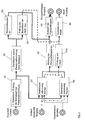
- FIG. 3 shows a signal flow diagram UML representation of an algorithm that is set up to carry out the method according to the invention.
- the algorithm provides the local flow temperature TV, the flow rate of the pump 5 as well as the switch-on state of the pump. The latter can only accept the pump on / off states. Using these input variables, the algorithm is able to determine the operating mode and to specify the output variables. There are two output variables “nominal delivery height" and "pump release”. With the target delivery height of the setpoint for the delivery of the centrifugal pump 5 is set. The pump enable is the enable signal that is sent to the centrifugal pump 5 to turn it on or off. Like the switch-on state, it assumes only the values "on" and "off”.
- the on state at the input is checked. If this signal is true (pump on), the determination of operating mode S7, S8 takes place. If it is wrong (pump off), a first waiting block S2 for the automatic pump activation S3, S4 is activated.
- the power-up state is "off", and thus the first power-up pump-on-waiting block S2 is activated.
- a second waiting block S1 upstream of the operating mode determination S7, S8 is skipped at the beginning of the method because the pump 5 is initially switched off.
- the first waiting block S2 provides that nothing happens for the duration of a first waiting time T1.
- the first waiting time T1 is for example 5 minutes, but can be changed manually or automatically. For this purpose, it is stored as a parameter in the algorithm. It makes sense to increase the wait time for the night mode, for example to 15 minutes, so that the algorithm does not switch to the mode check too often.
- the centrifugal pump 5 "sleeps" quasi and thus consumes no energy. For this reason, it does not supply a flow and can not be detected when the operating mode is changing or when a heating or cooling request is in the form of opening valves 11a-11d. Nevertheless, the centrifugal pump 5 must be reactivated at intervals to find out if there is a heating or cooling request or the mode has been switched and to service the request.
- the pump release is set to "on” via the algorithm, block S3, and the target delivery height is set to 100%, block S4.
- the maximum delivery head has been set to check the operating mode. At maximum delivery height, the maximum volume flow is established and it is thus checked whether there is a volume flow. In addition, the mixing of the flow temperature is faster.
- these are combined with a nominal delivery height coming from the operating mode determination S7, S8 and a likewise derived pump release, which may be "pump off", blocks S5, S6 ,
- the algorithm is constructed so that only one head can be present at a time.
- the head is selected in block S6.
- different delivery levels come in the block S6. Due to the different temperature limit ranges and the release signal, only the delivery height desired values 100% and 0%, 50% and 0%, 25% and 0% or 0% and 0% from the blocks S4 or S7 or S8 can be present at a time. In doing so, the higher value from the two present values is always assumed for the delivery amount.
- the higher priority is at the pump enable value "on”. The two signals for the pump release are therefore only ORED.
- the waiting time T2 is incorporated as a parameter and can be set individually.
- the pre-set second waiting time T2 is 1 minute, but can also be significantly less.
- This check may suitably be delayed in addition to the second waiting time, for example between 3 and 30 seconds, since there is a time difference between the pump release signal to the pump 5 and the feedback of the on-state of the pump 5. If this block S1 were omitted, the algorithm would switch immediately after the pump connection in S3, S5 in the operating mode determination S7, S8 and immediately turn off the pump 5 again immediately, because the mode determination still detects no flow. This is because, due to the delay in the pump 5, no volume flow can be present in such a short time.
- the second waiting time T2 ensures that a possible volume flow and the correct flow temperature can be set.
- the algorithm enters the two blocks S7, S8 for determining the operating mode.
- the first block S7 is for the detection of the operating mode "cooling”
- the second block S8 for the detection of the operating mode "heating”. Due to the different limit temperatures Tu.
- Tu To for the local flow temperature TV, only one of the two blocks S7, S8 can be active at a particular time. This is achieved in that the signal of the flow temperature in both blocks S7, S8 goes. Since each block S7, S8 considers its own temperature range, and these also do not overlap, only one of the two blocks S7, S8 can be active at a time, or neither.
- the two signals coming from the test blocks S9, S10 are passed on again and are now connected to the signals for the nominal delivery height from block S4 and the pump release from block S3 to the automatic pump activation. This is done in blocks S5, and S6. Also in block S6, only one target conveying height can be present at a time, which is guaranteed as described above. During pump release, priority is also given here to the "on" signal.
- the end signals for the pump release and nominal delivery height coming from blocks S5 and S6 form the outputs of the algorithm.
- FIG. 4 shows a flowchart illustrating the stepwise flow of the inventive method. Since the procedure differs in individual points, provides FIG. 4 in parts an alternative method variant to the signal flow diagram in FIG. 3 represents.
- the method according to FIG. 4 goes from the on state, block 30, to the algorithm FIG. 3 Input is.
- a check of the switch-on state first takes place as to whether the centrifugal pump 5 is switched on. This is not the case at the beginning of the method, so that it continues with the waiting block 34, which is the block S2 in FIG. 3 equivalent.
- the method then waits for a set first waiting time T1 which is here is also set at 5 minutes, and then proceeds to the automatic pump setting in block 36. Again, the first waiting time can be significantly shorter than 5 minutes.
- the centrifugal pump 5 is turned on. This corresponds -analog to FIG. 3 - setting the parameter "pump enable" to the state "on", which is indicated in block S3 in FIG. 3 he follows.
- the centrifugal pump 5 starts up and returns its on state, so that the parameter "on state” changes its value to "on". Since this does not take place immediately, the inquiry of the switch-on state in step 32 must not be continued immediately after the automatic pump switch-on 36. Because this would mean that the switch-on state may not have changed yet again and the no-branch of the case distinction 32 is passed through to the first wait block 34.
- the second waiting block 38 is present, which has a second waiting time T2 of one minute or significantly less, as in the algorithm according to FIG. 3 , owns.
- the second waiting block 38 corresponds to the waiting block S1 in FIG. 3 , As described above, the first and second waiting times T1, T2 can be changed, in particular manually or automatically.
- the operating mode detection leads to the determination of whether the operating mode "heating”, block 44, or the operating mode "cooling”, block 45, is present or whether the pump is switched off for lack of clear heating or cooling operation for energy saving can, block 46 operating mode "off". After the operation identifier, the process is continued again at block 30, ie repeated.
- the pump 5 is switched off by setting the pump enable to "off".
- the switch-on state confirmed by the pump 5 changes as a result. Since switching off the pump takes place relatively quickly, there is no need to wait for a waiting time in order to prevent the method from reentering the operating mode identifier 40. Instead, after switching off the pump (pump release off), the switch-on state immediately changes to "off", so that the case distinction 32 leads to the no branch. If the change of the "switch-on state" does not take place quickly, then the second wait block 38 can be set before the case distinction 42. This causes the second waiting time T2 to be waited for both when switching on and off the centrifugal pump 5, until the process is continued.
- the service identifier 40 may be implemented as follows. First follows a check of the flow temperature TV. For this purpose, in a case distinction 42 it is checked whether the flow temperature TV is greater than or equal to an upper limit temperature To, which is 30 ° C. by way of example here. If this is the case, heating mode is present, block 44. The pump 5 then remains switched on, but its setpoint delivery height Hsetpoint is set to 25% of the maximum delivery height Hmax of the centrifugal pump 5 in order to save energy.
- an upper limit temperature To which is 30 ° C. by way of example here. If this is the case, heating mode is present, block 44.
- the pump 5 then remains switched on, but its setpoint delivery height Hsetpoint is set to 25% of the maximum delivery height Hmax of the centrifugal pump 5 in order to save energy.
- a further case distinction 43 follows in the method, in which it is checked whether the flow temperature TV is less than a lower limit temperature Tu, which is 17 ° C here by way of example. If this is the case, cooling mode is present, block 45.
- the pump then likewise remains switched on, but its setpoint delivery height Hsetpoint is set to 50% of the maximum delivery height Hmax of the centrifugal pump 5.
- the flow temperature TV is not less than or equal to the lower limit temperature Tu, it follows in conjunction with the previous query in step 42 that the Flow temperature TV is obviously between the lower limit temperature Tu and the upper limit temperature To. As explained above, in this case, neither cooling nor heating is required, so that it is changed to the "off" mode, block 46.
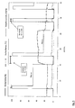
- FIG. 5 shows a diagram with curves for the head, the flow temperature TV, the flow rate and the pump release, which indicate the operating mode.
- the curves were taken during the operation of the algorithm or method.
- the heating / cooling ceilings 2a, 2b, 2c, 2d are in cooling mode.
- the flow temperature TV at the beginning of the test is 15 ° C.
- the algorithm does not start until the second auto-pump wait block, which lasts 5 minutes.
- T1 5min
- the pump release is set to "on” and the delivery height setpoint to maximum. This is done for the duration T2 of one minute.
- the check detects the "Cooling" operating mode and the pump control switches to cooling mode.
- the head Hsoll is lowered to 50% of the maximum head.
- the desired room temperatures of the zones 2a, 2b, 2c, 2d are increased and the heating / cooling ceilings change to the heating mode.
- the algorithm recognizes that the ceiling system 2 is no longer in cooling mode and the pump 5 is turned off or turns itself off.
- the operating mode is reset again from “heating” to “cooling” by setting lower setpoint temperatures for the zones 2a, 2b, 2c, 2d.
- the sequence with automatic pump activation and the operation mode check take place again.
- FIG. 5 shows that it is possible with the method to detect the operating mode of the consumer branch 1a by the flow temperature and thus automatically adjust the delivery height of the consumer-side centrifugal pump 5.
- the pump 5 can be switched off upon detection of the "off" mode and resume operation after a waiting time.
Landscapes
- Engineering & Computer Science (AREA)
- Mechanical Engineering (AREA)
- General Engineering & Computer Science (AREA)
- Physics & Mathematics (AREA)
- Thermal Sciences (AREA)
- Chemical & Material Sciences (AREA)
- Combustion & Propulsion (AREA)
- Control Of Non-Positive-Displacement Pumps (AREA)
Claims (16)
- Procédé de commande d'une pompe centrifuge (5) à vitesse variable d'un système de chauffage/refroidissement combiné (1) pouvant fonctionner en mode de chauffage et en mode de refroidissement et comprenant au moins un consommateur (2, 2a-2d), sachant que la pompe centrifuge (5) transporte un fluide issu d'un générateur de chaleur et de froid (3, 4) centralisé, caractérisé en ce que la pompe centrifuge (5) assume, à partir d'une température (TV, TR) du fluide, le mode de fonctionnement du système de chauffage/refroidissement (1) et adapte sa régulation en fonction de ce mode de fonctionnement assumé, sachant que la régulation de la pompe centrifuge (5) en mode de refroidissement se fait en fonction d'une première courbe caractéristique et en mode de chauffage à partir d'une seconde courbe caractéristique et que la valeur nominale de courbe caractéristique de la seconde courbe caractéristique est inférieure à la valeur nominale de courbe caractéristique de la première courbe caractéristique et sachant qu'un équipement commute sur la courbe caractéristique correspondante en fonction du mode de fonctionnement assumé.
- Procédé selon la revendication 1, caractérisé en ce que la pompe assume que le système est en mode de chauffage si la température (TV, TR) du fluide dépasse un seuil supérieur de température (To).
- Procédé selon la revendication 2, caractérisé en ce que le seuil supérieur de température (To) est dans une plage allant de 28°C à 32°C, particulièrement autour des 30°C.
- Procédé selon l'une des revendications précédentes, caractérisé en ce que la pompe assume que le système est en mode de refroidissement si la température (TV, TR) du fluide passe en dessous d'un seuil inférieur de température (Tu).
- Procédé selon l'une des revendications précédentes, caractérisé en ce que la température est la température d'aller (TV) ou la température de retour (TR) locale d'au moins un consommateur (2, 2a-2d).
- Procédé selon les revendications 4 ou 5, caractérisé en ce que le seuil inférieur de température (Tu) est dans une plage allant de 13°C à 17°C, particulièrement autour des 15°C.
- Procédé selon l'une des revendications précédentes, caractérisé en ce que, lorsque la pompe assume que le système est en mode de refroidissement, la hauteur manométrique nominale de la pompe centrifuge (5) est réduite à une valeur située entre 40% et 60% de la hauteur manométrique maximale, particulièrement autour des 50% de la hauteur manométrique maximale.
- Procédé selon l'une des revendications précédentes, caractérisé en ce que, lorsque la pompe assume que le système est en mode de chauffage, la hauteur manométrique nominale de la pompe centrifuge (5) est réduite à une valeur située entre 20% et 30% de la hauteur manométrique maximale, particulièrement autour des 25% de la hauteur manométrique maximale.
- Procédé selon l'une des revendications précédentes, caractérisé en ce que, lorsque la pompe assume que le système est en mode de chauffage, la hauteur manométrique nominale de la pompe centrifuge (5) destinée au mode de refroidissement est réduite selon un ratio de hauteur manométrique préréglable par rapport au mode de chauffage, particulièrement selon un ratio de 2:1.
- Procédé selon l'une des revendications 2 ou 3, renvoyant aux revendications 4 ou 5, caractérisé en ce que la pompe centrifuge (5) est arrêtée lorsque la température (TV, TR) du fluide est entre les seuils de température inférieur et supérieur (To, Tu).
- Procédé selon la revendication 10, caractérisé en ce que la pompe centrifuge (5) est arrêtée pendant un premier délai (T1) puis redémarrée après écoulement de ce premier délai.
- Procédé selon l'une des revendications précédentes, caractérisé en ce que la détermination du mode de fonctionnement après le démarrage de la pompe centrifuge (5) se fait après écoulement d'un second délai (T2).
- Procédé selon l'une des revendications précédentes, caractérisé en ce que la pompe centrifuge (5) pendant la détermination du mode de fonctionnement fonctionne à hauteur manométrique maximale.
- Pompe centrifuge (5) à vitesse variable pour un système de chauffage/refroidissement combiné (1) pouvant fonctionner en mode de chauffage et en mode de refroidissement, caractérisée en ce qu'elle présente un équipement (12) de mesure de la température (TV) du fluide qu'elle transporte et qu'elle est configurée pour assumer le mode de fonctionnement du système de chauffage/refroidissement (1) à partir de cette température (TV, TR) pour adapter de façon autonome sa régulation en fonction du mode de fonctionnement assumé, sachant que la régulation de la pompe centrifuge (5) en mode de refroidissement se fait en fonction d'une première courbe caractéristique et en mode de chauffage à partir d'une seconde courbe caractéristique et que la valeur nominale de courbe caractéristique de la seconde courbe caractéristique est inférieure à la valeur nominale de courbe caractéristique de la première courbe caractéristique et sachant que l'équipement (12) est configuré pour commuter sur la courbe caractéristique correspondante en fonction du mode de fonctionnement assumé.
- Pompe centrifuge selon la revendication 14, caractérisée en ce qu'elle présente un dispositif de détermination de son débit de transport et est configurée pour s'arrêter, au moins pendant une période déterminée, lorsque le débit de transport passe en-dessous d'un certain seuil.
- Pompe centrifuge selon les revendications 14 ou 15 caractérisée en ce qu'elle est configurée pour l'exécution du procédé selon l'une des revendications 1 à 13.
Applications Claiming Priority (1)
| Application Number | Priority Date | Filing Date | Title |
|---|---|---|---|
| DE102014019401.9A DE102014019401A1 (de) | 2014-12-31 | 2014-12-31 | Verfahren zur Steuerung einer drehzahlgeregelten Kreiselpumpe in einem kombinierten Heiz-Kühlsystem |
Publications (2)
| Publication Number | Publication Date |
|---|---|
| EP3040558A1 EP3040558A1 (fr) | 2016-07-06 |
| EP3040558B1 true EP3040558B1 (fr) | 2019-10-30 |
Family
ID=54849743
Family Applications (1)
| Application Number | Title | Priority Date | Filing Date |
|---|---|---|---|
| EP15003526.9A Active EP3040558B1 (fr) | 2014-12-31 | 2015-12-11 | Procédé de commande d'une pompe centrifuge à régulation de régime dans un système combiné refroidissement/chauffage et pompe centrifuge |
Country Status (2)
| Country | Link |
|---|---|
| EP (1) | EP3040558B1 (fr) |
| DE (1) | DE102014019401A1 (fr) |
Families Citing this family (1)
| Publication number | Priority date | Publication date | Assignee | Title |
|---|---|---|---|---|
| DE102017124916A1 (de) * | 2017-10-25 | 2019-04-25 | Miele & Cie. Kg | Steuereinheit für eine Fluidfördervorrichtung |
Family Cites Families (4)
| Publication number | Priority date | Publication date | Assignee | Title |
|---|---|---|---|---|
| JP3298026B2 (ja) * | 1993-03-02 | 2002-07-02 | 矢崎総業株式会社 | 冷温水ポンプの運転装置 |
| JP4699285B2 (ja) * | 2006-05-29 | 2011-06-08 | 株式会社 長谷川電気工業所 | 空調設備における冷温水ポンプの運転制御方法 |
| DE102010016344A1 (de) * | 2010-04-07 | 2011-10-13 | Wolf Gmbh | Wärmepumpenanlage und Verfahren zur Regelung einer Wärmepumpenanlage |
| DE202013002275U1 (de) * | 2013-03-11 | 2014-06-12 | Stiebel Eltron Gmbh & Co. Kg | Wärmepumpeneinrichtung |
-
2014
- 2014-12-31 DE DE102014019401.9A patent/DE102014019401A1/de not_active Withdrawn
-
2015
- 2015-12-11 EP EP15003526.9A patent/EP3040558B1/fr active Active
Non-Patent Citations (1)
| Title |
|---|
| AQUATHERM: "Sistemi innovativi in polipropilene fusiolen Sistemi di riscaldamento e raffrescamento a parete e a soffitto 800-259925", 1 March 2010 (2010-03-01), www.Aquatherm.de, pages 1 - 4, XP055434549, Retrieved from the Internet <URL:http://www.aquatherm-pipesystems.com/fileadmin/_migrated/content_uploads/Catalogo_climasystem.pdf> [retrieved on 20171212] * |
Also Published As
| Publication number | Publication date |
|---|---|
| EP3040558A1 (fr) | 2016-07-06 |
| DE102014019401A1 (de) | 2016-06-30 |
Similar Documents
| Publication | Publication Date | Title |
|---|---|---|
| EP2871423B1 (fr) | Procédé de régulation pour un système de chauffage et/ou de refroidissement comprenant au moins un circuit de charge et dispositif de distribution pour un système de chauffage et/ou de refroidissement | |
| DE102012002941B4 (de) | Verfahren zum Betrieb einer Heizungs- oder Kühlanlage sowie Heizungs- und Kühlanlage | |
| EP3593055B1 (fr) | Procédé pour faire fonctionner une installation de chauffage | |
| EP3443228B1 (fr) | Ensemble pompe centrifuge et procédé de réglage de son fonctionnement | |
| EP2087291A1 (fr) | Système d'équilibrage pour un ensemble d'apport de température voulue par le sol | |
| EP2645018A2 (fr) | Appareil de réfrigération et/ou de congélation | |
| EP4259978A1 (fr) | Procédé de fonctionnement d'une pompe à chaleur | |
| EP2871539B1 (fr) | Procédé de diagnostic pour le diagnostic du fonctionnement correct d'un système de chauffage et/ou de refroidissement | |
| EP3473939B1 (fr) | Procédé de fonctionnement d'une installation de chauffage et installation de chauffage | |
| DE102015114474A1 (de) | Wärmepumpenanlage und Verfahren zum Betrieb einer Wärmepumpenanlage | |
| EP2871424B1 (fr) | Procédé de régulation pour un système de chauffage et/ou de refroidissement et dispositif de distribution pour un système de chauffage et/ou de refroidissement | |
| EP3924670B1 (fr) | Procédé pour réguler une pompe de circulation et pompe de circulation | |
| EP3040558B1 (fr) | Procédé de commande d'une pompe centrifuge à régulation de régime dans un système combiné refroidissement/chauffage et pompe centrifuge | |
| EP2413047B2 (fr) | Unité de chauffage d'eau potable | |
| EP3800403B1 (fr) | Procédé de fonctionnement d'un dispositif de chauffage, dispositif de chauffage | |
| DE10259279B3 (de) | Versorgungssystem für Heiz-oder Kühlwasser sowie Verfahren zum Betreiben desselben | |
| DE102010056301B4 (de) | Verfahren zur automatischen Optimierung einer Aufheizphase eines Heizsystems sowie ein Heizsystem | |
| EP0195255A2 (fr) | Procédé et dispositif de régulation de température de locaux | |
| EP3062026B1 (fr) | Systeme de regulation de la temperature | |
| EP3023709B1 (fr) | Procede de chauffage d'un fluide dans un reservoir dans une installation de chauffage et installation de chauffage associee | |
| EP1003089B2 (fr) | Régulation en fonction de la demande pour un dispositif de transfert de chaleur | |
| EP3467316A1 (fr) | Procédé de démarrage d'une pompe de circulation et pompe de circulation associée | |
| EP2905671A2 (fr) | Procédé de synchronisation d'une installation thermique avec un système thermique | |
| EP2863135A1 (fr) | Optimisation de température de consigne pour une partie en attente dans des installations de chauffage, en particulier pour le chauffage d'eau potable | |
| EP4563909A1 (fr) | Procédé de récupération d'énergie améliorée dans des échangeurs de chaleur d'air d'admission et d'échappement de systèmes composites à circulation pour des installations de climatisation et de ventilation |
Legal Events
| Date | Code | Title | Description |
|---|---|---|---|
| PUAI | Public reference made under article 153(3) epc to a published international application that has entered the european phase |
Free format text: ORIGINAL CODE: 0009012 |
|
| AK | Designated contracting states |
Kind code of ref document: A1 Designated state(s): AL AT BE BG CH CY CZ DE DK EE ES FI FR GB GR HR HU IE IS IT LI LT LU LV MC MK MT NL NO PL PT RO RS SE SI SK SM TR |
|
| AX | Request for extension of the european patent |
Extension state: BA ME |
|
| 17P | Request for examination filed |
Effective date: 20160728 |
|
| RBV | Designated contracting states (corrected) |
Designated state(s): AL AT BE BG CH CY CZ DE DK EE ES FI FR GB GR HR HU IE IS IT LI LT LU LV MC MK MT NL NO PL PT RO RS SE SI SK SM TR |
|
| STAA | Information on the status of an ep patent application or granted ep patent |
Free format text: STATUS: EXAMINATION IS IN PROGRESS |
|
| 17Q | First examination report despatched |
Effective date: 20171219 |
|
| GRAP | Despatch of communication of intention to grant a patent |
Free format text: ORIGINAL CODE: EPIDOSNIGR1 |
|
| STAA | Information on the status of an ep patent application or granted ep patent |
Free format text: STATUS: GRANT OF PATENT IS INTENDED |
|
| INTG | Intention to grant announced |
Effective date: 20190603 |
|
| GRAS | Grant fee paid |
Free format text: ORIGINAL CODE: EPIDOSNIGR3 |
|
| GRAA | (expected) grant |
Free format text: ORIGINAL CODE: 0009210 |
|
| STAA | Information on the status of an ep patent application or granted ep patent |
Free format text: STATUS: THE PATENT HAS BEEN GRANTED |
|
| AK | Designated contracting states |
Kind code of ref document: B1 Designated state(s): AL AT BE BG CH CY CZ DE DK EE ES FI FR GB GR HR HU IE IS IT LI LT LU LV MC MK MT NL NO PL PT RO RS SE SI SK SM TR |
|
| REG | Reference to a national code |
Ref country code: GB Ref legal event code: FG4D Free format text: NOT ENGLISH |
|
| REG | Reference to a national code |
Ref country code: CH Ref legal event code: EP |
|
| REG | Reference to a national code |
Ref country code: AT Ref legal event code: REF Ref document number: 1196438 Country of ref document: AT Kind code of ref document: T Effective date: 20191115 |
|
| REG | Reference to a national code |
Ref country code: DE Ref legal event code: R096 Ref document number: 502015010768 Country of ref document: DE |
|
| REG | Reference to a national code |
Ref country code: IE Ref legal event code: FG4D Free format text: LANGUAGE OF EP DOCUMENT: GERMAN |
|
| REG | Reference to a national code |
Ref country code: LT Ref legal event code: MG4D |
|
| PG25 | Lapsed in a contracting state [announced via postgrant information from national office to epo] |
Ref country code: NL Free format text: LAPSE BECAUSE OF FAILURE TO SUBMIT A TRANSLATION OF THE DESCRIPTION OR TO PAY THE FEE WITHIN THE PRESCRIBED TIME-LIMIT Effective date: 20191030 Ref country code: SE Free format text: LAPSE BECAUSE OF FAILURE TO SUBMIT A TRANSLATION OF THE DESCRIPTION OR TO PAY THE FEE WITHIN THE PRESCRIBED TIME-LIMIT Effective date: 20191030 Ref country code: LV Free format text: LAPSE BECAUSE OF FAILURE TO SUBMIT A TRANSLATION OF THE DESCRIPTION OR TO PAY THE FEE WITHIN THE PRESCRIBED TIME-LIMIT Effective date: 20191030 Ref country code: PL Free format text: LAPSE BECAUSE OF FAILURE TO SUBMIT A TRANSLATION OF THE DESCRIPTION OR TO PAY THE FEE WITHIN THE PRESCRIBED TIME-LIMIT Effective date: 20191030 Ref country code: NO Free format text: LAPSE BECAUSE OF FAILURE TO SUBMIT A TRANSLATION OF THE DESCRIPTION OR TO PAY THE FEE WITHIN THE PRESCRIBED TIME-LIMIT Effective date: 20200130 Ref country code: BG Free format text: LAPSE BECAUSE OF FAILURE TO SUBMIT A TRANSLATION OF THE DESCRIPTION OR TO PAY THE FEE WITHIN THE PRESCRIBED TIME-LIMIT Effective date: 20200130 Ref country code: FI Free format text: LAPSE BECAUSE OF FAILURE TO SUBMIT A TRANSLATION OF THE DESCRIPTION OR TO PAY THE FEE WITHIN THE PRESCRIBED TIME-LIMIT Effective date: 20191030 Ref country code: PT Free format text: LAPSE BECAUSE OF FAILURE TO SUBMIT A TRANSLATION OF THE DESCRIPTION OR TO PAY THE FEE WITHIN THE PRESCRIBED TIME-LIMIT Effective date: 20200302 Ref country code: GR Free format text: LAPSE BECAUSE OF FAILURE TO SUBMIT A TRANSLATION OF THE DESCRIPTION OR TO PAY THE FEE WITHIN THE PRESCRIBED TIME-LIMIT Effective date: 20200131 Ref country code: LT Free format text: LAPSE BECAUSE OF FAILURE TO SUBMIT A TRANSLATION OF THE DESCRIPTION OR TO PAY THE FEE WITHIN THE PRESCRIBED TIME-LIMIT Effective date: 20191030 |
|
| REG | Reference to a national code |
Ref country code: NL Ref legal event code: MP Effective date: 20191030 |
|
| PG25 | Lapsed in a contracting state [announced via postgrant information from national office to epo] |
Ref country code: HR Free format text: LAPSE BECAUSE OF FAILURE TO SUBMIT A TRANSLATION OF THE DESCRIPTION OR TO PAY THE FEE WITHIN THE PRESCRIBED TIME-LIMIT Effective date: 20191030 Ref country code: IS Free format text: LAPSE BECAUSE OF FAILURE TO SUBMIT A TRANSLATION OF THE DESCRIPTION OR TO PAY THE FEE WITHIN THE PRESCRIBED TIME-LIMIT Effective date: 20200229 Ref country code: RS Free format text: LAPSE BECAUSE OF FAILURE TO SUBMIT A TRANSLATION OF THE DESCRIPTION OR TO PAY THE FEE WITHIN THE PRESCRIBED TIME-LIMIT Effective date: 20191030 |
|
| PG25 | Lapsed in a contracting state [announced via postgrant information from national office to epo] |
Ref country code: AL Free format text: LAPSE BECAUSE OF FAILURE TO SUBMIT A TRANSLATION OF THE DESCRIPTION OR TO PAY THE FEE WITHIN THE PRESCRIBED TIME-LIMIT Effective date: 20191030 |
|
| PG25 | Lapsed in a contracting state [announced via postgrant information from national office to epo] |
Ref country code: CZ Free format text: LAPSE BECAUSE OF FAILURE TO SUBMIT A TRANSLATION OF THE DESCRIPTION OR TO PAY THE FEE WITHIN THE PRESCRIBED TIME-LIMIT Effective date: 20191030 Ref country code: ES Free format text: LAPSE BECAUSE OF FAILURE TO SUBMIT A TRANSLATION OF THE DESCRIPTION OR TO PAY THE FEE WITHIN THE PRESCRIBED TIME-LIMIT Effective date: 20191030 Ref country code: RO Free format text: LAPSE BECAUSE OF FAILURE TO SUBMIT A TRANSLATION OF THE DESCRIPTION OR TO PAY THE FEE WITHIN THE PRESCRIBED TIME-LIMIT Effective date: 20191030 Ref country code: EE Free format text: LAPSE BECAUSE OF FAILURE TO SUBMIT A TRANSLATION OF THE DESCRIPTION OR TO PAY THE FEE WITHIN THE PRESCRIBED TIME-LIMIT Effective date: 20191030 Ref country code: DK Free format text: LAPSE BECAUSE OF FAILURE TO SUBMIT A TRANSLATION OF THE DESCRIPTION OR TO PAY THE FEE WITHIN THE PRESCRIBED TIME-LIMIT Effective date: 20191030 |
|
| REG | Reference to a national code |
Ref country code: CH Ref legal event code: PL Ref country code: DE Ref legal event code: R097 Ref document number: 502015010768 Country of ref document: DE |
|
| REG | Reference to a national code |
Ref country code: BE Ref legal event code: MM Effective date: 20191231 |
|
| PG25 | Lapsed in a contracting state [announced via postgrant information from national office to epo] |
Ref country code: SM Free format text: LAPSE BECAUSE OF FAILURE TO SUBMIT A TRANSLATION OF THE DESCRIPTION OR TO PAY THE FEE WITHIN THE PRESCRIBED TIME-LIMIT Effective date: 20191030 Ref country code: MC Free format text: LAPSE BECAUSE OF FAILURE TO SUBMIT A TRANSLATION OF THE DESCRIPTION OR TO PAY THE FEE WITHIN THE PRESCRIBED TIME-LIMIT Effective date: 20191030 Ref country code: SK Free format text: LAPSE BECAUSE OF FAILURE TO SUBMIT A TRANSLATION OF THE DESCRIPTION OR TO PAY THE FEE WITHIN THE PRESCRIBED TIME-LIMIT Effective date: 20191030 |
|
| PLBE | No opposition filed within time limit |
Free format text: ORIGINAL CODE: 0009261 |
|
| STAA | Information on the status of an ep patent application or granted ep patent |
Free format text: STATUS: NO OPPOSITION FILED WITHIN TIME LIMIT |
|
| 26N | No opposition filed |
Effective date: 20200731 |
|
| PG25 | Lapsed in a contracting state [announced via postgrant information from national office to epo] |
Ref country code: LU Free format text: LAPSE BECAUSE OF NON-PAYMENT OF DUE FEES Effective date: 20191211 Ref country code: IE Free format text: LAPSE BECAUSE OF NON-PAYMENT OF DUE FEES Effective date: 20191211 |
|
| PG25 | Lapsed in a contracting state [announced via postgrant information from national office to epo] |
Ref country code: CH Free format text: LAPSE BECAUSE OF NON-PAYMENT OF DUE FEES Effective date: 20191231 Ref country code: LI Free format text: LAPSE BECAUSE OF NON-PAYMENT OF DUE FEES Effective date: 20191231 Ref country code: BE Free format text: LAPSE BECAUSE OF NON-PAYMENT OF DUE FEES Effective date: 20191231 Ref country code: SI Free format text: LAPSE BECAUSE OF FAILURE TO SUBMIT A TRANSLATION OF THE DESCRIPTION OR TO PAY THE FEE WITHIN THE PRESCRIBED TIME-LIMIT Effective date: 20191030 |
|
| PG25 | Lapsed in a contracting state [announced via postgrant information from national office to epo] |
Ref country code: CY Free format text: LAPSE BECAUSE OF FAILURE TO SUBMIT A TRANSLATION OF THE DESCRIPTION OR TO PAY THE FEE WITHIN THE PRESCRIBED TIME-LIMIT Effective date: 20191030 |
|
| PG25 | Lapsed in a contracting state [announced via postgrant information from national office to epo] |
Ref country code: MT Free format text: LAPSE BECAUSE OF FAILURE TO SUBMIT A TRANSLATION OF THE DESCRIPTION OR TO PAY THE FEE WITHIN THE PRESCRIBED TIME-LIMIT Effective date: 20191030 Ref country code: HU Free format text: LAPSE BECAUSE OF FAILURE TO SUBMIT A TRANSLATION OF THE DESCRIPTION OR TO PAY THE FEE WITHIN THE PRESCRIBED TIME-LIMIT; INVALID AB INITIO Effective date: 20151211 |
|
| REG | Reference to a national code |
Ref country code: AT Ref legal event code: MM01 Ref document number: 1196438 Country of ref document: AT Kind code of ref document: T Effective date: 20201211 |
|
| PG25 | Lapsed in a contracting state [announced via postgrant information from national office to epo] |
Ref country code: AT Free format text: LAPSE BECAUSE OF NON-PAYMENT OF DUE FEES Effective date: 20201211 |
|
| PG25 | Lapsed in a contracting state [announced via postgrant information from national office to epo] |
Ref country code: TR Free format text: LAPSE BECAUSE OF FAILURE TO SUBMIT A TRANSLATION OF THE DESCRIPTION OR TO PAY THE FEE WITHIN THE PRESCRIBED TIME-LIMIT Effective date: 20191030 |
|
| PG25 | Lapsed in a contracting state [announced via postgrant information from national office to epo] |
Ref country code: MK Free format text: LAPSE BECAUSE OF FAILURE TO SUBMIT A TRANSLATION OF THE DESCRIPTION OR TO PAY THE FEE WITHIN THE PRESCRIBED TIME-LIMIT Effective date: 20191030 |
|
| P01 | Opt-out of the competence of the unified patent court (upc) registered |
Effective date: 20230615 |
|
| PGFP | Annual fee paid to national office [announced via postgrant information from national office to epo] |
Ref country code: DE Payment date: 20251126 Year of fee payment: 11 |
|
| PGFP | Annual fee paid to national office [announced via postgrant information from national office to epo] |
Ref country code: GB Payment date: 20251120 Year of fee payment: 11 |
|
| PGFP | Annual fee paid to national office [announced via postgrant information from national office to epo] |
Ref country code: IT Payment date: 20251119 Year of fee payment: 11 |
|
| PGFP | Annual fee paid to national office [announced via postgrant information from national office to epo] |
Ref country code: FR Payment date: 20251120 Year of fee payment: 11 |