EP3040596A1 - Beinverriegelungsvorrichtung für ein dreibeinstativ - Google Patents
Beinverriegelungsvorrichtung für ein dreibeinstativ Download PDFInfo
- Publication number
- EP3040596A1 EP3040596A1 EP15002395.0A EP15002395A EP3040596A1 EP 3040596 A1 EP3040596 A1 EP 3040596A1 EP 15002395 A EP15002395 A EP 15002395A EP 3040596 A1 EP3040596 A1 EP 3040596A1
- Authority
- EP
- European Patent Office
- Prior art keywords
- buckle
- leg
- cam
- buckle base
- locking device
- Prior art date
- Legal status (The legal status is an assumption and is not a legal conclusion. Google has not performed a legal analysis and makes no representation as to the accuracy of the status listed.)
- Withdrawn
Links
Images



Classifications
-
- F—MECHANICAL ENGINEERING; LIGHTING; HEATING; WEAPONS; BLASTING
- F16—ENGINEERING ELEMENTS AND UNITS; GENERAL MEASURES FOR PRODUCING AND MAINTAINING EFFECTIVE FUNCTIONING OF MACHINES OR INSTALLATIONS; THERMAL INSULATION IN GENERAL
- F16B—DEVICES FOR FASTENING OR SECURING CONSTRUCTIONAL ELEMENTS OR MACHINE PARTS TOGETHER, e.g. NAILS, BOLTS, CIRCLIPS, CLAMPS, CLIPS OR WEDGES; JOINTS OR JOINTING
- F16B7/00—Connections of rods or tubes, e.g. of non-circular section, mutually, including resilient connections
- F16B7/10—Telescoping systems
- F16B7/14—Telescoping systems locking in intermediate non-discrete positions
- F16B7/1454—Telescoping systems locking in intermediate non-discrete positions with a clamp locking the telescoping members by swinging a handle provided with a locking cam
-
- A—HUMAN NECESSITIES
- A63—SPORTS; GAMES; AMUSEMENTS
- A63C—SKATES; SKIS; ROLLER SKATES; DESIGN OR LAYOUT OF COURTS, RINKS OR THE LIKE
- A63C11/00—Accessories for skiing or snowboarding
- A63C11/22—Ski-sticks
- A63C11/221—Ski-sticks telescopic, e.g. for varying the length or for damping shocks
-
- F—MECHANICAL ENGINEERING; LIGHTING; HEATING; WEAPONS; BLASTING
- F16—ENGINEERING ELEMENTS AND UNITS; GENERAL MEASURES FOR PRODUCING AND MAINTAINING EFFECTIVE FUNCTIONING OF MACHINES OR INSTALLATIONS; THERMAL INSULATION IN GENERAL
- F16B—DEVICES FOR FASTENING OR SECURING CONSTRUCTIONAL ELEMENTS OR MACHINE PARTS TOGETHER, e.g. NAILS, BOLTS, CIRCLIPS, CLAMPS, CLIPS OR WEDGES; JOINTS OR JOINTING
- F16B7/00—Connections of rods or tubes, e.g. of non-circular section, mutually, including resilient connections
- F16B7/10—Telescoping systems
- F16B7/14—Telescoping systems locking in intermediate non-discrete positions
- F16B7/1472—Telescoping systems locking in intermediate non-discrete positions with a clamping screw perpendicular to the axis of the telescoping members
-
- F—MECHANICAL ENGINEERING; LIGHTING; HEATING; WEAPONS; BLASTING
- F16—ENGINEERING ELEMENTS AND UNITS; GENERAL MEASURES FOR PRODUCING AND MAINTAINING EFFECTIVE FUNCTIONING OF MACHINES OR INSTALLATIONS; THERMAL INSULATION IN GENERAL
- F16M—FRAMES, CASINGS OR BEDS OF ENGINES, MACHINES OR APPARATUS, NOT SPECIFIC TO ENGINES, MACHINES OR APPARATUS PROVIDED FOR ELSEWHERE; STANDS; SUPPORTS
- F16M11/00—Stands or trestles as supports for apparatus or articles placed thereon ; Stands for scientific apparatus such as gravitational force meters
- F16M11/20—Undercarriages with or without wheels
- F16M11/24—Undercarriages with or without wheels changeable in height or length of legs, also for transport only, e.g. by means of tubes screwed into each other
- F16M11/26—Undercarriages with or without wheels changeable in height or length of legs, also for transport only, e.g. by means of tubes screwed into each other by telescoping, with or without folding
- F16M11/32—Undercarriages for supports with three or more telescoping legs
-
- F—MECHANICAL ENGINEERING; LIGHTING; HEATING; WEAPONS; BLASTING
- F16—ENGINEERING ELEMENTS AND UNITS; GENERAL MEASURES FOR PRODUCING AND MAINTAINING EFFECTIVE FUNCTIONING OF MACHINES OR INSTALLATIONS; THERMAL INSULATION IN GENERAL
- F16M—FRAMES, CASINGS OR BEDS OF ENGINES, MACHINES OR APPARATUS, NOT SPECIFIC TO ENGINES, MACHINES OR APPARATUS PROVIDED FOR ELSEWHERE; STANDS; SUPPORTS
- F16M13/00—Other supports for positioning apparatus or articles; Means for steadying hand-held apparatus or articles
- F16M13/02—Other supports for positioning apparatus or articles; Means for steadying hand-held apparatus or articles for supporting on, or attaching to, an object, e.g. tree, gate, window-frame, cycle
-
- F—MECHANICAL ENGINEERING; LIGHTING; HEATING; WEAPONS; BLASTING
- F16—ENGINEERING ELEMENTS AND UNITS; GENERAL MEASURES FOR PRODUCING AND MAINTAINING EFFECTIVE FUNCTIONING OF MACHINES OR INSTALLATIONS; THERMAL INSULATION IN GENERAL
- F16M—FRAMES, CASINGS OR BEDS OF ENGINES, MACHINES OR APPARATUS, NOT SPECIFIC TO ENGINES, MACHINES OR APPARATUS PROVIDED FOR ELSEWHERE; STANDS; SUPPORTS
- F16M2200/00—Details of stands or supports
- F16M2200/02—Locking means
- F16M2200/025—Locking means for translational movement
- F16M2200/027—Locking means for translational movement by friction
Definitions
- the present application relates to a leg locking device for a tripod, which falls into the technical field of accessories for photographic equipments.
- the leg buckle assembly of the existing photographic tripod is mostly locked by assembling with a buckle through screw arbor and screw thread.
- this locking structure can achieve the locking function, it has disadvantages: the locking structure is so bulky and heavy that it makes the overall size and weight of the tripod not convenient to carry; in addition, the locking process is neither convenientnor easy to operate.
- the present application in order to conquer the shortcomings in the prior art, provides a leg locking device for a tripod.
- the leg locking device for a tripod further comprises an adjustment structure that is fixed on the buckle base, with one end of the adjustment structure pressed on the leg, to adjust the locking extent;
- the specific structure of the adjustment structure is as following: the adjustment structure comprises a compact and an adjustment screw; the compact is placed between the buckle base and the leg; the adjustment screw is turned to penetrate the buckle base and is pressed onto the compact; through turning the adjustment screw to adjust the force of the compact on the leg, the degree of tightness of the whole locking device is adjusted.
- the cam is connected to the buckle base through an inserting shaft.
- the advantageous effects of the present application is: in the present utility mode, a buckle shaft is connected to one end of the buckle through shaft, and the steel belt is fixed at the other end reversely after rounding the cam of the buckle; by using of the principle of cam rotation, the cam gradually increases the pulling force on the steel belt during rotation, so that the buckle base is deformed and compressed on the leg; when the cam is rotated to the maximum distance, the cam is still continuously rotated to make the pinch plate pressed onto the buckle base under the reaction force of the steel belt, so that the leg is rapidly locked.
- the present application is of simple structure, small size, light weight, easy carrying, easy operation, and wide applicability.
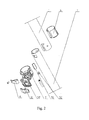
- a leg locking device for a tripod in this embodiment comprises a buckle base 2 that telescopes a leg 1, a buckle 3, a steel belt 4 and an adjustment structure 5; the leg 1 is telescoped with an opening finger 6 inside; a leg connecting tube 7 is telescoped in the opening finger 6 and can be pulled freely inside the opening finger 6; the buckle base 2 is in a form of a circular ring and is arranged with an opening; the buckle 3 comprises a cam 31 and a pinch plate 32; the cam 31 is, through an inserting shaft, connected to one end of the buckle base 2; one end of the pinch plate 32 is fixed on the cam 31, and the other end of the pinch plate 32 bends into an arc inward along the buckle base 2; the steel belt 4 rounds the cam 31 and is fixed at the other end of the buckle base 2 reversely with the pinch plate 32; the adjustment structure 5 is fixed on the buckle base 2, with one end of the adjustment structure 5 pressed on the leg 1.
- the leg connecting tube 7 is connected with the leg 1 through the opening finger 6, which can prevent the leg connecting tube 7 from being damaged by pressure when the leg 1 is deformed under the pressure of the buckle base; the adjustment structure 5 is mainly used to adjust the degree of tightness of the whole locking device.
- the buckle 3 is, through shaft, connected to one end of the buckle base 2; by using of the principle of cam rotation, the cam 31 gradually increases the pulling force on the steel belt 4 during rotation, so that the buckle base 2 is deformed and compressed on the leg 1; when the cam 31 is rotated to the maximum distance, under the reaction force of the steel belt 4, the cam 31 is continuously rotated to make the pinch plate 32 of the buckle 3 pressed onto the buckle base 2, so that the leg is rapidly locked, as the status shown by Figure 1 .
- the specific structure of the adjustment structure 5 is as following: the adjustment structure 5 comprises a compact 51 and an adjustment screw 52, wherein the compact 51 is placed between the buckle base 2 and the leg 1, and the adjustment screw 52 is turned to penetrate the buckle base 2 and pressed onto the compact 51; through turning the adjustment screw 52 to adjust the force of the compact 51 on the leg 1, the degree of tightness of the whole locking device is adjusted.
- the adjustment structure 5 can also adopt other structures, as far as it can realize the function of adjusting the tightness of the whole locking device.
Landscapes
- Engineering & Computer Science (AREA)
- General Engineering & Computer Science (AREA)
- Mechanical Engineering (AREA)
- Accessories Of Cameras (AREA)
Applications Claiming Priority (1)
| Application Number | Priority Date | Filing Date | Title |
|---|---|---|---|
| CN201420843756.8U CN204387598U (zh) | 2014-12-25 | 2014-12-25 | 三脚架脚管锁紧装置 |
Publications (1)
| Publication Number | Publication Date |
|---|---|
| EP3040596A1 true EP3040596A1 (de) | 2016-07-06 |
Family
ID=53360317
Family Applications (1)
| Application Number | Title | Priority Date | Filing Date |
|---|---|---|---|
| EP15002395.0A Withdrawn EP3040596A1 (de) | 2014-12-25 | 2015-08-12 | Beinverriegelungsvorrichtung für ein dreibeinstativ |
Country Status (3)
| Country | Link |
|---|---|
| US (1) | US20160186791A1 (de) |
| EP (1) | EP3040596A1 (de) |
| CN (1) | CN204387598U (de) |
Families Citing this family (11)
| Publication number | Priority date | Publication date | Assignee | Title |
|---|---|---|---|---|
| US9713759B2 (en) * | 2015-02-02 | 2017-07-25 | Andrew D. Liebner | Ski pole accessories |
| CN106264383A (zh) * | 2015-06-11 | 2017-01-04 | 慈溪市博生塑料制品有限公司 | 一种用于平板拖的手压旋转式拖把杆 |
| CN105423075B (zh) * | 2015-12-24 | 2017-08-29 | 中山宝益五金塑胶制品有限公司 | 一种偏心圆转动锁紧结构 |
| CN108006416B (zh) * | 2017-11-24 | 2024-07-12 | 陈小鸣 | 一种肩托式摄影支架 |
| CN110115619B (zh) * | 2018-02-07 | 2024-05-03 | 北京纳通医疗科技控股有限公司 | 一种凸轮锁紧机构 |
| CN108843936A (zh) * | 2018-08-10 | 2018-11-20 | 浙江智合精图地理信息科技有限公司 | 测绘用三脚架的快速锁紧机构 |
| CN109578952A (zh) * | 2019-01-22 | 2019-04-05 | 王赵健 | 固定架 |
| US11698092B2 (en) * | 2020-06-22 | 2023-07-11 | Unger Marketing International | Telescopic pole for a cleaning implement |
| CN215861166U (zh) * | 2021-04-01 | 2022-02-18 | 乐清市创意影视器材有限公司 | 一种脚管锁紧机构及三脚架 |
| CN217130877U (zh) * | 2022-04-14 | 2022-08-05 | 中山市科曼摄影器材有限公司 | 紧凑型摄影支架 |
| US11988322B2 (en) * | 2022-06-03 | 2024-05-21 | Braden Hourigan | Tripod design and manufacture |
Citations (3)
| Publication number | Priority date | Publication date | Assignee | Title |
|---|---|---|---|---|
| FR683058A (fr) * | 1929-10-10 | 1930-06-05 | Fermeture pour colliers de serrage pour tuyauteries | |
| US5074600A (en) * | 1989-10-30 | 1991-12-24 | Karl Weinhold | Device for connecting the end of a hose to a connecting spigot |
| AU2014101295A4 (en) * | 2013-10-23 | 2014-11-20 | Chervon (Hk) Limited | Locking Device, Telescopic Rod And Mower Including The Locking Device |
Family Cites Families (8)
| Publication number | Priority date | Publication date | Assignee | Title |
|---|---|---|---|---|
| US2653836A (en) * | 1948-09-04 | 1953-09-29 | Marman Products Company Inc | Reinforced v-band clamp |
| US3820831A (en) * | 1973-02-20 | 1974-06-28 | J Swedelius | Coupling for connecting aligned tubes |
| US4761092A (en) * | 1984-10-05 | 1988-08-02 | Koma Nakatani | Lock for telescoping tubular leg |
| US6142699A (en) * | 1998-04-21 | 2000-11-07 | Asia Link Co., Ltd. | Telescopic rod |
| US6322027B1 (en) * | 2000-06-26 | 2001-11-27 | Ching-Tien Hsu | Adjustable sprinkler stand |
| JP2002089779A (ja) * | 2000-09-12 | 2002-03-27 | Nippon Berubon Seiki Kogyo Kk | ストッパ具および伸縮装置 |
| US7320485B2 (en) * | 2003-10-16 | 2008-01-22 | Breeze-Torca Products, Llc | V insert edge contour |
| WO2010085905A1 (de) * | 2009-01-29 | 2010-08-05 | Lekisport Ag | Längenverstellbarer stock und klemmvorrichtung dafür |
-
2014
- 2014-12-25 CN CN201420843756.8U patent/CN204387598U/zh not_active Expired - Fee Related
-
2015
- 2015-07-02 US US14/790,327 patent/US20160186791A1/en not_active Abandoned
- 2015-08-12 EP EP15002395.0A patent/EP3040596A1/de not_active Withdrawn
Patent Citations (3)
| Publication number | Priority date | Publication date | Assignee | Title |
|---|---|---|---|---|
| FR683058A (fr) * | 1929-10-10 | 1930-06-05 | Fermeture pour colliers de serrage pour tuyauteries | |
| US5074600A (en) * | 1989-10-30 | 1991-12-24 | Karl Weinhold | Device for connecting the end of a hose to a connecting spigot |
| AU2014101295A4 (en) * | 2013-10-23 | 2014-11-20 | Chervon (Hk) Limited | Locking Device, Telescopic Rod And Mower Including The Locking Device |
Also Published As
| Publication number | Publication date |
|---|---|
| US20160186791A1 (en) | 2016-06-30 |
| CN204387598U (zh) | 2015-06-10 |
Similar Documents
| Publication | Publication Date | Title |
|---|---|---|
| EP3040596A1 (de) | Beinverriegelungsvorrichtung für ein dreibeinstativ | |
| US8146879B2 (en) | Umbrella holder | |
| US10724671B2 (en) | Quick release connection structures, support structures, and remote controllers | |
| US20170089375A1 (en) | Telescoping Pipe Fitting | |
| US7581703B1 (en) | Radial tripod stabilizer | |
| US7007909B2 (en) | Locking device for a telescopic tube assembly | |
| US20150353215A1 (en) | Membrane strapping apparatus | |
| NZ602624A (en) | Drive system | |
| AU2013286648B2 (en) | Wrench with grip enhancing apparatus | |
| HK1217460A1 (zh) | 锻炼装置 | |
| AU2014393342B2 (en) | Telescopic rod for hand tool | |
| CN207747963U (zh) | 夹持装置 | |
| CN109083904A (zh) | 一种搭扣 | |
| CN224079924U (zh) | 一种伸缩支脚、多脚支架及拍摄支架 | |
| CN203703526U (zh) | 锁紧定位装置 | |
| AU2010214665B2 (en) | Umbrella Holder | |
| CN203532444U (zh) | 一种活动式快拆装置 | |
| KR101693298B1 (ko) | 휴대기기 홀더 | |
| KR101504086B1 (ko) | 봉의 회전방지 및 길이 조절이 용이한 셀프 카메라용 모노포드 | |
| CN204387637U (zh) | 支架结构以及采用该支架结构的遥控器 | |
| GB2489549B (en) | Annular clamp | |
| CN204921674U (zh) | 一种提拉式角度调节快锁机构 | |
| CN207523518U (zh) | 一种便携式可伸缩公交拉环 | |
| CN207644533U (zh) | 固定支架 | |
| CN108953955A (zh) | 一种旋转调节和宽度调节的两级手机夹具 |
Legal Events
| Date | Code | Title | Description |
|---|---|---|---|
| PUAI | Public reference made under article 153(3) epc to a published international application that has entered the european phase |
Free format text: ORIGINAL CODE: 0009012 |
|
| AK | Designated contracting states |
Kind code of ref document: A1 Designated state(s): AL AT BE BG CH CY CZ DE DK EE ES FI FR GB GR HR HU IE IS IT LI LT LU LV MC MK MT NL NO PL PT RO RS SE SI SK SM TR |
|
| AX | Request for extension of the european patent |
Extension state: BA ME |
|
| STAA | Information on the status of an ep patent application or granted ep patent |
Free format text: STATUS: THE APPLICATION IS DEEMED TO BE WITHDRAWN |
|
| 18D | Application deemed to be withdrawn |
Effective date: 20170110 |