EP3040799B1 - Liquid flow control device - Google Patents
Liquid flow control device Download PDFInfo
- Publication number
- EP3040799B1 EP3040799B1 EP15192942.9A EP15192942A EP3040799B1 EP 3040799 B1 EP3040799 B1 EP 3040799B1 EP 15192942 A EP15192942 A EP 15192942A EP 3040799 B1 EP3040799 B1 EP 3040799B1
- Authority
- EP
- European Patent Office
- Prior art keywords
- piece
- liquid flow
- flow control
- control device
- liquid
- Prior art date
- Legal status (The legal status is an assumption and is not a legal conclusion. Google has not performed a legal analysis and makes no representation as to the accuracy of the status listed.)
- Active
Links
Images


Classifications
-
- G—PHYSICS
- G05—CONTROLLING; REGULATING
- G05D—SYSTEMS FOR CONTROLLING OR REGULATING NON-ELECTRIC VARIABLES
- G05D7/00—Control of flow
- G05D7/01—Control of flow without auxiliary power
- G05D7/0106—Control of flow without auxiliary power the sensing element being a flexible member, e.g. bellows, diaphragm, capsule
- G05D7/012—Control of flow without auxiliary power the sensing element being a flexible member, e.g. bellows, diaphragm, capsule the sensing element being deformable and acting as a valve
Definitions
- the present invention refers to a liquid flow control device in shower-hose single-lever tap cartridges, handsets, shower sprayers, etc.
- the device of the invention is, firstly, capable of maintaining a constant outlet flow despite variations in the liquid pressure and, secondly, capable of minimizing the noise level produced by the flow of said liquid at its outlet.
- control device of the invention is highly versatile, being also applicable to other devices and apparatuses that are not taps, where there is a liquid passage and the device of the invention may be mounted.
- control devices usually give rise to clogging problems as a consequence of the systems employed to achieve said control, normally based on the existence of multiple micro-holes which become clogged with elements reacting to pressure increases, so that water impurities end up clogging them, thus leaving them inoperative.
- the invention proposes a liquid control device intended to be installed in a liquid passage to maintain a constant flow of said liquid.
- It comprises at least a first liquid flow control piece containing a through orifice with a controllable passage section of the liquid flow, wherein the controllable passage section varies based on the water pressure affecting a deformable tubular extension that defines said controllable passage section that comprises the through orifice.
- the pressure difference of the circulating liquid on an inner surface and outer surface of the tubular extension modifies the controllable passage section maintaining a constant flow of the liquid; the device being coupled to a support body.
- the first piece is manufactured with an elastomeric material.
- said support body is a single-lever tap cartridge.
- the through orifice of the first piece contains an end stretch constituting the controllable passage section composed of the tubular extension.
- the exterior of said tubular extension is defined by an external annular channel that is flooded with liquid. An increase in the liquid pressure within the external annular channel bends and deforms the circular extension inwards, thus reducing the passage of circulating liquid.
- the external annular channel of the first piece contains angular cross section in angular shape with a vertex, as a bottom, that is rounded.
- the tubular extension of the first piece contains a tapered configuration, whose minor annular base composes a tapered mouth in inverted position which converges inwards to the through orifice of the first piece.
- the through orifice of the first piece features a tapered configuration with an inner generatrix that is a curved line convergent towards the direction of the entrance of the liquid.
- the device of the invention also comprises a second piece that dampens the noise level of the liquid flow circulating through the first piece and the second piece, both pieces being located respectively in the first box and in a second box, both located in the support body.
- the second piece maintains the position of the first piece placed upstream the second piece.
- incorporation of an additional first piece is considered, which is placed in the opposite place of the second piece with respect to the first piece.
- the second piece contains an open cavity for the passage of water that incorporates in its interior some reliefs which reduce the sound level of the liquid circulation, wherein said open cavity is defined by a bottom and an encasing lateral side.
- said reliefs comprise aligned tapered lugs which are arranged from the bottom of the open cavity of the second piece, wherein said tapered lugs are joined to the bottom through their bigger bases, whereas their smaller bases are composed of curved-convex surfaces.
- the reliefs comprise a gear tooth pattern located in an inner part of the encasing lateral side of the open cavity.
- the reliefs comprise prismatic lugs aligned progressively based on their height which are arranged from the bottom of the open cavity of the second piece; wherein said prismatic lugs are joined to the bottom of the open cavity through some of their bases, whereas the opposite bases are composed of inclined planes, being the highest prismatic lug joined to the innermost part of the encasing lateral side of the open cavity.
- the second piece holds a T-shaped cross section structure, in the vertical crossbar of which the open cavity is formed.
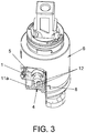
- the liquid flow control device comprises a first water flow control piece (1) manufactured with an elastomeric material, preferably silicone, which contains a through orifice (2) with a controllable passage section (2a) of the water flow that varies based on the water pressure affecting a tubular extension (3) that defines said controllable passage section (2a) comprising the through orifice (2).
- a first water flow control piece (1) manufactured with an elastomeric material, preferably silicone, which contains a through orifice (2) with a controllable passage section (2a) of the water flow that varies based on the water pressure affecting a tubular extension (3) that defines said controllable passage section (2a) comprising the through orifice (2).
- the device of the invention is complemented with a second piece (4) that minimizes and dampens the noise level of the water flow while circulating through the controllable passage section (2a) of the first piece (1) and through the second piece (4).
- the first piece (1) is adjusted within the first box (5) of a single-lever tap cartridge (6) and the second piece (4) is adjusted within a second box (8) of that same cartridge (6), so that the second piece (4), apart from performing its specific function of minimizing the noise level of the water, also performs the function of maintaining the first piece (1) within its first box (5). It is worth noting that the first box (5) is located in a position more inside the cartridge than the second box (8).
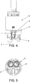
- the first piece (1) for the liquid flow control has the through orifice (2) through which the water flow circulates, so that said through orifice (2) comprises an end stretch constituting the controllable passage section (2a) composed of the tubular extension (3), the exterior of which is defined by an external annular channel (10) that is flooded with water.
- An increase in the pressure of said water within the external annular channel (10) bends and deforms the tubular extension (3) inwards of the first piece (1), choking the passage of water while circulating through the controllable passage section (2a) of the first piece (1).
- the water flow circulating through the controllable passage section (2a) of the first piece (1) is always kept constant, both when there is pressure difference between the external annular channel (10) and the controllable passage section (2a), and when the pressures are balanced in both areas (2a, 10), in such a way that in this case the tubular extension (3) remains stable without bending or deforming.
- the device of the invention is complemented with the second piece (4) acting as a lid (4), which apart from helping to maintain the first piece (1) in its place as it has been previously referred to, in the body of the single-lever tap cartridge (6), said second piece (4) is provided with an internal geometry that minimizes the noise level caused in the outlet of the first flow control piece (1), in such a way that the water circulates through the first piece (1) and also through the second piece (4).
- the external annular channel (10) of the first piece (1) contains a cross section in an angular shape with a vertex, as a bottom (10a), that is rounded.
- the tubular extension (3) of said first piece (1) features a hollow tapered configuration.
- the generatrix of the outer surface of the tubular extension (3) is a straight line that is simultaneously part of the external annular channel (10).
- the generatrix of the inner surface of the tubular extension (3) is a curved line convergent towards the direction of the entrance of liquid.
- Both the inner and outer surfaces are joined with a minor annular base (3a) that composes a tapered mouth in an inverted position with respect to the entrance of liquid.
- the first piece (1) is composed of a flat base (1a) which leans against the second piece (4), in order to maintain the first piece (1) for the water flow control.
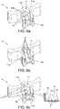
- the second piece (4) holds a T-shaped structure, in the vertical cross-bar (4a) of which an open cavity (11) is formed for water passage containing reliefs inside according to the three embodiments shown in the figures 6a, 6b and 6c depending on the noise level to be reduced.
- Said open cavity (11) is defined by a closed bottom (11a) and an encasing lateral side (11b) that is open by the free end of the vertical crossbar (4a).
- the reliefs comprise aligned tapered lugs (12) which are arranged from the bottom (11a) of the open cavity (11) of the second piece (4). Said tapered lugs (12) are joined to the bottom (11a) through their bigger bases (12a), whereas their smaller bases are rounded.
- the reliefs comprise a gear tooth pattern (9) located in an inner part of the encasing lateral side (11b) of the open cavity (11).
- the reliefs comprise prismatic lugs (7) progressively aligned based on their height which are arranged from the bottom (11a) of the open cavity (11) of the second piece (4).
- These prismatic lugs (7) are joined to the bottom (11a) of the open cavity (11) through some of their bases, whereas the opposite bases are composed of inclined planes (7a).
- the highest prismatic lug (7) is joined to the innermost part of the encasing lateral side (11b) of the open cavity (11), confluence of the two bars forming the "T" shape.
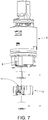
- an additional first piece (1') has been considered, having an external circular shape placed in the opposite side of the second piece (4) with respect to the first piece (1), such that in this embodiment the first piece (1) is placed upstream the second piece (4) and an additional first piece (1') is placed downstream said second piece (4) controlling the noise level of the water.
- the internal structure of the additional first piece (1') is the same as the internal structure of the first piece (1).
- the reliefs of the second piece (4) may have geometries and distributions different from those shown in the Figures, depending on the application of the product and the flow needed to be achieved, such that said flow restricts both the diameter of the through orifice (2) of the first piece (1) and the size thereof; thus forcing the redesign of the reliefs of the second piece (4) until the maximum reduction of noise is attained.
Landscapes
- Physics & Mathematics (AREA)
- General Physics & Mathematics (AREA)
- Engineering & Computer Science (AREA)
- Automation & Control Theory (AREA)
- Details Of Valves (AREA)
- Pipe Accessories (AREA)
- Flow Control (AREA)
- Structures Of Non-Positive Displacement Pumps (AREA)
- Hydraulic Turbines (AREA)
- Domestic Plumbing Installations (AREA)
Priority Applications (1)
| Application Number | Priority Date | Filing Date | Title |
|---|---|---|---|
| PL15192942T PL3040799T3 (pl) | 2014-12-30 | 2015-11-04 | Urządzenie sterujące przepływem cieczy |
Applications Claiming Priority (1)
| Application Number | Priority Date | Filing Date | Title |
|---|---|---|---|
| ES201431692U ES1135597Y (es) | 2014-12-30 | 2014-12-30 | Dispositivo controlador de caudal de un fluido liquido |
Publications (2)
| Publication Number | Publication Date |
|---|---|
| EP3040799A1 EP3040799A1 (en) | 2016-07-06 |
| EP3040799B1 true EP3040799B1 (en) | 2020-01-01 |
Family
ID=52355314
Family Applications (1)
| Application Number | Title | Priority Date | Filing Date |
|---|---|---|---|
| EP15192942.9A Active EP3040799B1 (en) | 2014-12-30 | 2015-11-04 | Liquid flow control device |
Country Status (3)
| Country | Link |
|---|---|
| EP (1) | EP3040799B1 (pl) |
| ES (2) | ES1135597Y (pl) |
| PL (1) | PL3040799T3 (pl) |
Families Citing this family (1)
| Publication number | Priority date | Publication date | Assignee | Title |
|---|---|---|---|---|
| ES2960259B2 (es) * | 2022-08-02 | 2024-09-30 | Tucai Sa | Base de entrada de agua para un grifo monomando |
Family Cites Families (4)
| Publication number | Priority date | Publication date | Assignee | Title |
|---|---|---|---|---|
| GB699446A (en) * | 1951-09-06 | 1953-11-04 | Gen Electric | Improvements in and relating to flow control devices |
| US4161965A (en) * | 1977-02-25 | 1979-07-24 | Merritt Thurman L | Water-flow control device |
| US5209265A (en) * | 1990-04-14 | 1993-05-11 | Matsushita Electric Works, Ltd. | Flow control device with restrictor |
| ITVI20100302A1 (it) * | 2010-11-12 | 2012-05-13 | Arno Drechsel | Dispositivo irrigatore a getto a flusso variabile |
-
2014
- 2014-12-30 ES ES201431692U patent/ES1135597Y/es not_active Expired - Fee Related
-
2015
- 2015-11-04 EP EP15192942.9A patent/EP3040799B1/en active Active
- 2015-11-04 PL PL15192942T patent/PL3040799T3/pl unknown
- 2015-11-04 ES ES15192942T patent/ES2777278T3/es active Active
Non-Patent Citations (1)
| Title |
|---|
| None * |
Also Published As
| Publication number | Publication date |
|---|---|
| PL3040799T3 (pl) | 2020-07-13 |
| ES1135597U (es) | 2015-01-27 |
| EP3040799A1 (en) | 2016-07-06 |
| ES1135597Y (es) | 2015-04-17 |
| ES2777278T3 (es) | 2020-08-04 |
Similar Documents
| Publication | Publication Date | Title |
|---|---|---|
| US8566975B1 (en) | Faucet control structure | |
| US9377128B2 (en) | Flow-volume regulator | |
| US9353509B2 (en) | Elongate continuous flow controller with web-shaped or string-shaped flow restrictor | |
| EP3015611B1 (en) | Lavatory drain | |
| US20170185090A1 (en) | Sanitary insertion unit | |
| US20180345179A1 (en) | Hose line, and filter screen for a hose line | |
| CA2647104C (en) | Spout including a stream straightener | |
| US9038927B2 (en) | Plumbing spout device | |
| CN103764924B (zh) | 流量调节器 | |
| US11213835B2 (en) | Water-saving nozzle | |
| US11213172B2 (en) | Drain fixture | |
| US10022734B2 (en) | Variable dual flow fitting | |
| EP3040799A1 (en) | Liquid flow control device | |
| CN101815828B (zh) | 射流调节器 | |
| US8408231B2 (en) | Pressure balance valve | |
| JP6001700B2 (ja) | シャワーヘッドのシャワー吐水部構造 | |
| US10415219B2 (en) | Fluid restriction nozzle for hand washing | |
| US10907639B2 (en) | Suction pipe inlet device for centrifugal pump | |
| EP3394357B1 (en) | A flushing apparatus | |
| KR101737023B1 (ko) | 유량 균등형 다단 분기식 절수 수전구 | |
| KR101794926B1 (ko) | 유량 균등형 급수 시스템 | |
| JP2015175166A (ja) | 吐水装置 | |
| JP2016104930A (ja) | 散水板構造およびシャワーヘッド | |
| NL2035598B1 (en) | Flow regulating device | |
| JP6017196B2 (ja) | バキュームブレーカ |
Legal Events
| Date | Code | Title | Description |
|---|---|---|---|
| PUAI | Public reference made under article 153(3) epc to a published international application that has entered the european phase |
Free format text: ORIGINAL CODE: 0009012 |
|
| AK | Designated contracting states |
Kind code of ref document: A1 Designated state(s): AL AT BE BG CH CY CZ DE DK EE ES FI FR GB GR HR HU IE IS IT LI LT LU LV MC MK MT NL NO PL PT RO RS SE SI SK SM TR |
|
| AX | Request for extension of the european patent |
Extension state: BA ME |
|
| STAA | Information on the status of an ep patent application or granted ep patent |
Free format text: STATUS: REQUEST FOR EXAMINATION WAS MADE |
|
| 17P | Request for examination filed |
Effective date: 20161223 |
|
| RBV | Designated contracting states (corrected) |
Designated state(s): AL AT BE BG CH CY CZ DE DK EE ES FI FR GB GR HR HU IE IS IT LI LT LU LV MC MK MT NL NO PL PT RO RS SE SI SK SM TR |
|
| REG | Reference to a national code |
Ref country code: DE Ref legal event code: R079 Ref document number: 602015044556 Country of ref document: DE Free format text: PREVIOUS MAIN CLASS: G05D0007010000 Ipc: F16K0011000000 |
|
| RIC1 | Information provided on ipc code assigned before grant |
Ipc: G05D 7/01 20060101ALI20190619BHEP Ipc: F16K 11/00 20060101AFI20190619BHEP |
|
| GRAP | Despatch of communication of intention to grant a patent |
Free format text: ORIGINAL CODE: EPIDOSNIGR1 |
|
| STAA | Information on the status of an ep patent application or granted ep patent |
Free format text: STATUS: GRANT OF PATENT IS INTENDED |
|
| INTG | Intention to grant announced |
Effective date: 20190906 |
|
| RIN1 | Information on inventor provided before grant (corrected) |
Inventor name: TRES CASAS, DANIEL |
|
| GRAS | Grant fee paid |
Free format text: ORIGINAL CODE: EPIDOSNIGR3 |
|
| GRAA | (expected) grant |
Free format text: ORIGINAL CODE: 0009210 |
|
| STAA | Information on the status of an ep patent application or granted ep patent |
Free format text: STATUS: THE PATENT HAS BEEN GRANTED |
|
| AK | Designated contracting states |
Kind code of ref document: B1 Designated state(s): AL AT BE BG CH CY CZ DE DK EE ES FI FR GB GR HR HU IE IS IT LI LT LU LV MC MK MT NL NO PL PT RO RS SE SI SK SM TR |
|
| REG | Reference to a national code |
Ref country code: GB Ref legal event code: FG4D |
|
| REG | Reference to a national code |
Ref country code: CH Ref legal event code: EP Ref country code: AT Ref legal event code: REF Ref document number: 1220180 Country of ref document: AT Kind code of ref document: T Effective date: 20200115 |
|
| REG | Reference to a national code |
Ref country code: IE Ref legal event code: FG4D |
|
| REG | Reference to a national code |
Ref country code: DE Ref legal event code: R096 Ref document number: 602015044556 Country of ref document: DE |
|
| REG | Reference to a national code |
Ref country code: NL Ref legal event code: MP Effective date: 20200101 |
|
| REG | Reference to a national code |
Ref country code: LT Ref legal event code: MG4D |
|
| PG25 | Lapsed in a contracting state [announced via postgrant information from national office to epo] |
Ref country code: CZ Free format text: LAPSE BECAUSE OF FAILURE TO SUBMIT A TRANSLATION OF THE DESCRIPTION OR TO PAY THE FEE WITHIN THE PRESCRIBED TIME-LIMIT Effective date: 20200101 Ref country code: FI Free format text: LAPSE BECAUSE OF FAILURE TO SUBMIT A TRANSLATION OF THE DESCRIPTION OR TO PAY THE FEE WITHIN THE PRESCRIBED TIME-LIMIT Effective date: 20200101 Ref country code: NO Free format text: LAPSE BECAUSE OF FAILURE TO SUBMIT A TRANSLATION OF THE DESCRIPTION OR TO PAY THE FEE WITHIN THE PRESCRIBED TIME-LIMIT Effective date: 20200401 Ref country code: RS Free format text: LAPSE BECAUSE OF FAILURE TO SUBMIT A TRANSLATION OF THE DESCRIPTION OR TO PAY THE FEE WITHIN THE PRESCRIBED TIME-LIMIT Effective date: 20200101 Ref country code: LT Free format text: LAPSE BECAUSE OF FAILURE TO SUBMIT A TRANSLATION OF THE DESCRIPTION OR TO PAY THE FEE WITHIN THE PRESCRIBED TIME-LIMIT Effective date: 20200101 Ref country code: PT Free format text: LAPSE BECAUSE OF FAILURE TO SUBMIT A TRANSLATION OF THE DESCRIPTION OR TO PAY THE FEE WITHIN THE PRESCRIBED TIME-LIMIT Effective date: 20200527 Ref country code: NL Free format text: LAPSE BECAUSE OF FAILURE TO SUBMIT A TRANSLATION OF THE DESCRIPTION OR TO PAY THE FEE WITHIN THE PRESCRIBED TIME-LIMIT Effective date: 20200101 |
|
| REG | Reference to a national code |
Ref country code: ES Ref legal event code: FG2A Ref document number: 2777278 Country of ref document: ES Kind code of ref document: T3 Effective date: 20200804 |
|
| PG25 | Lapsed in a contracting state [announced via postgrant information from national office to epo] |
Ref country code: IS Free format text: LAPSE BECAUSE OF FAILURE TO SUBMIT A TRANSLATION OF THE DESCRIPTION OR TO PAY THE FEE WITHIN THE PRESCRIBED TIME-LIMIT Effective date: 20200501 Ref country code: BG Free format text: LAPSE BECAUSE OF FAILURE TO SUBMIT A TRANSLATION OF THE DESCRIPTION OR TO PAY THE FEE WITHIN THE PRESCRIBED TIME-LIMIT Effective date: 20200401 Ref country code: GR Free format text: LAPSE BECAUSE OF FAILURE TO SUBMIT A TRANSLATION OF THE DESCRIPTION OR TO PAY THE FEE WITHIN THE PRESCRIBED TIME-LIMIT Effective date: 20200402 Ref country code: SE Free format text: LAPSE BECAUSE OF FAILURE TO SUBMIT A TRANSLATION OF THE DESCRIPTION OR TO PAY THE FEE WITHIN THE PRESCRIBED TIME-LIMIT Effective date: 20200101 Ref country code: LV Free format text: LAPSE BECAUSE OF FAILURE TO SUBMIT A TRANSLATION OF THE DESCRIPTION OR TO PAY THE FEE WITHIN THE PRESCRIBED TIME-LIMIT Effective date: 20200101 Ref country code: HR Free format text: LAPSE BECAUSE OF FAILURE TO SUBMIT A TRANSLATION OF THE DESCRIPTION OR TO PAY THE FEE WITHIN THE PRESCRIBED TIME-LIMIT Effective date: 20200101 |
|
| REG | Reference to a national code |
Ref country code: DE Ref legal event code: R097 Ref document number: 602015044556 Country of ref document: DE |
|
| PG25 | Lapsed in a contracting state [announced via postgrant information from national office to epo] |
Ref country code: DK Free format text: LAPSE BECAUSE OF FAILURE TO SUBMIT A TRANSLATION OF THE DESCRIPTION OR TO PAY THE FEE WITHIN THE PRESCRIBED TIME-LIMIT Effective date: 20200101 Ref country code: RO Free format text: LAPSE BECAUSE OF FAILURE TO SUBMIT A TRANSLATION OF THE DESCRIPTION OR TO PAY THE FEE WITHIN THE PRESCRIBED TIME-LIMIT Effective date: 20200101 Ref country code: SK Free format text: LAPSE BECAUSE OF FAILURE TO SUBMIT A TRANSLATION OF THE DESCRIPTION OR TO PAY THE FEE WITHIN THE PRESCRIBED TIME-LIMIT Effective date: 20200101 Ref country code: EE Free format text: LAPSE BECAUSE OF FAILURE TO SUBMIT A TRANSLATION OF THE DESCRIPTION OR TO PAY THE FEE WITHIN THE PRESCRIBED TIME-LIMIT Effective date: 20200101 Ref country code: SM Free format text: LAPSE BECAUSE OF FAILURE TO SUBMIT A TRANSLATION OF THE DESCRIPTION OR TO PAY THE FEE WITHIN THE PRESCRIBED TIME-LIMIT Effective date: 20200101 |
|
| PLBE | No opposition filed within time limit |
Free format text: ORIGINAL CODE: 0009261 |
|
| STAA | Information on the status of an ep patent application or granted ep patent |
Free format text: STATUS: NO OPPOSITION FILED WITHIN TIME LIMIT |
|
| REG | Reference to a national code |
Ref country code: AT Ref legal event code: MK05 Ref document number: 1220180 Country of ref document: AT Kind code of ref document: T Effective date: 20200101 |
|
| 26N | No opposition filed |
Effective date: 20201002 |
|
| PG25 | Lapsed in a contracting state [announced via postgrant information from national office to epo] |
Ref country code: AT Free format text: LAPSE BECAUSE OF FAILURE TO SUBMIT A TRANSLATION OF THE DESCRIPTION OR TO PAY THE FEE WITHIN THE PRESCRIBED TIME-LIMIT Effective date: 20200101 |
|
| PG25 | Lapsed in a contracting state [announced via postgrant information from national office to epo] |
Ref country code: SI Free format text: LAPSE BECAUSE OF FAILURE TO SUBMIT A TRANSLATION OF THE DESCRIPTION OR TO PAY THE FEE WITHIN THE PRESCRIBED TIME-LIMIT Effective date: 20200101 |
|
| PG25 | Lapsed in a contracting state [announced via postgrant information from national office to epo] |
Ref country code: MC Free format text: LAPSE BECAUSE OF FAILURE TO SUBMIT A TRANSLATION OF THE DESCRIPTION OR TO PAY THE FEE WITHIN THE PRESCRIBED TIME-LIMIT Effective date: 20200101 |
|
| REG | Reference to a national code |
Ref country code: CH Ref legal event code: PL |
|
| GBPC | Gb: european patent ceased through non-payment of renewal fee |
Effective date: 20201104 |
|
| PG25 | Lapsed in a contracting state [announced via postgrant information from national office to epo] |
Ref country code: LU Free format text: LAPSE BECAUSE OF NON-PAYMENT OF DUE FEES Effective date: 20201104 |
|
| REG | Reference to a national code |
Ref country code: BE Ref legal event code: MM Effective date: 20201130 |
|
| PG25 | Lapsed in a contracting state [announced via postgrant information from national office to epo] |
Ref country code: CH Free format text: LAPSE BECAUSE OF NON-PAYMENT OF DUE FEES Effective date: 20201130 Ref country code: LI Free format text: LAPSE BECAUSE OF NON-PAYMENT OF DUE FEES Effective date: 20201130 |
|
| PG25 | Lapsed in a contracting state [announced via postgrant information from national office to epo] |
Ref country code: IE Free format text: LAPSE BECAUSE OF NON-PAYMENT OF DUE FEES Effective date: 20201104 |
|
| PG25 | Lapsed in a contracting state [announced via postgrant information from national office to epo] |
Ref country code: GB Free format text: LAPSE BECAUSE OF NON-PAYMENT OF DUE FEES Effective date: 20201104 |
|
| PG25 | Lapsed in a contracting state [announced via postgrant information from national office to epo] |
Ref country code: TR Free format text: LAPSE BECAUSE OF FAILURE TO SUBMIT A TRANSLATION OF THE DESCRIPTION OR TO PAY THE FEE WITHIN THE PRESCRIBED TIME-LIMIT Effective date: 20200101 Ref country code: MT Free format text: LAPSE BECAUSE OF FAILURE TO SUBMIT A TRANSLATION OF THE DESCRIPTION OR TO PAY THE FEE WITHIN THE PRESCRIBED TIME-LIMIT Effective date: 20200101 Ref country code: CY Free format text: LAPSE BECAUSE OF FAILURE TO SUBMIT A TRANSLATION OF THE DESCRIPTION OR TO PAY THE FEE WITHIN THE PRESCRIBED TIME-LIMIT Effective date: 20200101 |
|
| PG25 | Lapsed in a contracting state [announced via postgrant information from national office to epo] |
Ref country code: MK Free format text: LAPSE BECAUSE OF FAILURE TO SUBMIT A TRANSLATION OF THE DESCRIPTION OR TO PAY THE FEE WITHIN THE PRESCRIBED TIME-LIMIT Effective date: 20200101 Ref country code: AL Free format text: LAPSE BECAUSE OF FAILURE TO SUBMIT A TRANSLATION OF THE DESCRIPTION OR TO PAY THE FEE WITHIN THE PRESCRIBED TIME-LIMIT Effective date: 20200101 |
|
| PG25 | Lapsed in a contracting state [announced via postgrant information from national office to epo] |
Ref country code: BE Free format text: LAPSE BECAUSE OF NON-PAYMENT OF DUE FEES Effective date: 20201130 |
|
| PGFP | Annual fee paid to national office [announced via postgrant information from national office to epo] |
Ref country code: PL Payment date: 20220929 Year of fee payment: 8 Ref country code: FR Payment date: 20220907 Year of fee payment: 8 |
|
| PGFP | Annual fee paid to national office [announced via postgrant information from national office to epo] |
Ref country code: IT Payment date: 20221111 Year of fee payment: 8 Ref country code: DE Payment date: 20221123 Year of fee payment: 8 |
|
| P01 | Opt-out of the competence of the unified patent court (upc) registered |
Effective date: 20230527 |
|
| REG | Reference to a national code |
Ref country code: DE Ref legal event code: R119 Ref document number: 602015044556 Country of ref document: DE |
|
| PG25 | Lapsed in a contracting state [announced via postgrant information from national office to epo] |
Ref country code: DE Free format text: LAPSE BECAUSE OF NON-PAYMENT OF DUE FEES Effective date: 20240601 |
|
| PG25 | Lapsed in a contracting state [announced via postgrant information from national office to epo] |
Ref country code: FR Free format text: LAPSE BECAUSE OF NON-PAYMENT OF DUE FEES Effective date: 20231130 |
|
| PG25 | Lapsed in a contracting state [announced via postgrant information from national office to epo] |
Ref country code: FR Free format text: LAPSE BECAUSE OF NON-PAYMENT OF DUE FEES Effective date: 20231130 Ref country code: DE Free format text: LAPSE BECAUSE OF NON-PAYMENT OF DUE FEES Effective date: 20240601 |
|
| PG25 | Lapsed in a contracting state [announced via postgrant information from national office to epo] |
Ref country code: IT Free format text: LAPSE BECAUSE OF NON-PAYMENT OF DUE FEES Effective date: 20231104 |
|
| PG25 | Lapsed in a contracting state [announced via postgrant information from national office to epo] |
Ref country code: IT Free format text: LAPSE BECAUSE OF NON-PAYMENT OF DUE FEES Effective date: 20231104 |
|
| PG25 | Lapsed in a contracting state [announced via postgrant information from national office to epo] |
Ref country code: PL Free format text: LAPSE BECAUSE OF NON-PAYMENT OF DUE FEES Effective date: 20231104 |
|
| PGFP | Annual fee paid to national office [announced via postgrant information from national office to epo] |
Ref country code: ES Payment date: 20251201 Year of fee payment: 11 |