EP3041394B1 - Brush for cleaning equipment - Google Patents
Brush for cleaning equipment Download PDFInfo
- Publication number
- EP3041394B1 EP3041394B1 EP14790313.2A EP14790313A EP3041394B1 EP 3041394 B1 EP3041394 B1 EP 3041394B1 EP 14790313 A EP14790313 A EP 14790313A EP 3041394 B1 EP3041394 B1 EP 3041394B1
- Authority
- EP
- European Patent Office
- Prior art keywords
- bristles
- movement mechanism
- brush
- bristle
- lever
- Prior art date
- Legal status (The legal status is an assumption and is not a legal conclusion. Google has not performed a legal analysis and makes no representation as to the accuracy of the status listed.)
- Active
Links
- 238000004140 cleaning Methods 0.000 title claims description 21
- 230000007246 mechanism Effects 0.000 claims description 85
- 239000004744 fabric Substances 0.000 description 6
- 239000000428 dust Substances 0.000 description 4
- 230000008901 benefit Effects 0.000 description 3
- 230000004913 activation Effects 0.000 description 2
- 230000000694 effects Effects 0.000 description 2
- 238000009434 installation Methods 0.000 description 2
- 239000000463 material Substances 0.000 description 2
- 239000002245 particle Substances 0.000 description 2
- 229920000642 polymer Polymers 0.000 description 2
- 239000002023 wood Substances 0.000 description 2
- 230000003213 activating effect Effects 0.000 description 1
- 238000007792 addition Methods 0.000 description 1
- 239000006227 byproduct Substances 0.000 description 1
- 239000000919 ceramic Substances 0.000 description 1
- 230000001419 dependent effect Effects 0.000 description 1
- 238000009408 flooring Methods 0.000 description 1
- 239000011521 glass Substances 0.000 description 1
- 239000004579 marble Substances 0.000 description 1
- 230000013011 mating Effects 0.000 description 1
- 230000004048 modification Effects 0.000 description 1
- 238000012986 modification Methods 0.000 description 1
- 229920005989 resin Polymers 0.000 description 1
- 239000011347 resin Substances 0.000 description 1
- 229920002994 synthetic fiber Polymers 0.000 description 1
Images


Classifications
-
- A—HUMAN NECESSITIES
- A47—FURNITURE; DOMESTIC ARTICLES OR APPLIANCES; COFFEE MILLS; SPICE MILLS; SUCTION CLEANERS IN GENERAL
- A47L—DOMESTIC WASHING OR CLEANING; SUCTION CLEANERS IN GENERAL
- A47L9/00—Details or accessories of suction cleaners, e.g. mechanical means for controlling the suction or for effecting pulsating action; Storing devices specially adapted to suction cleaners or parts thereof; Carrying-vehicles specially adapted for suction cleaners
- A47L9/02—Nozzles
- A47L9/06—Nozzles with fixed, e.g. adjustably fixed brushes or the like
- A47L9/0633—Nozzles with fixed, e.g. adjustably fixed brushes or the like with retractable brushes, combs, lips or pads
- A47L9/064—Nozzles with fixed, e.g. adjustably fixed brushes or the like with retractable brushes, combs, lips or pads actuating means therefor
- A47L9/0653—Nozzles with fixed, e.g. adjustably fixed brushes or the like with retractable brushes, combs, lips or pads actuating means therefor with mechanical actuation, e.g. using a lever
-
- A—HUMAN NECESSITIES
- A47—FURNITURE; DOMESTIC ARTICLES OR APPLIANCES; COFFEE MILLS; SPICE MILLS; SUCTION CLEANERS IN GENERAL
- A47L—DOMESTIC WASHING OR CLEANING; SUCTION CLEANERS IN GENERAL
- A47L9/00—Details or accessories of suction cleaners, e.g. mechanical means for controlling the suction or for effecting pulsating action; Storing devices specially adapted to suction cleaners or parts thereof; Carrying-vehicles specially adapted for suction cleaners
- A47L9/02—Nozzles
- A47L9/06—Nozzles with fixed, e.g. adjustably fixed brushes or the like
- A47L9/066—Nozzles with fixed, e.g. adjustably fixed brushes or the like with adjustably mounted brushes, combs, lips or pads; Height adjustment of nozzle or dust loosening tools
Definitions
- the present invention concerns a brush usable as an end accessory on cleaning equipment, such as vacuum cleaners, electric brushes, combined apparatuses to vacuum and wash floors , or centralized domestic vacuum plants.
- the present invention is usable both for cleaning smooth surfaces or surfaces covered by tiles, or parquet made of wood or any of its by-products or substitutes, or with laminate or any other polymer coverings, or for cleaning rugs or fitted carpets or other surfaces covered in fabric, for example cushions or furnishing elements.
- Brushes for generic use are known, suitable for sucking up dust and gathering dirt present on common surfaces, smooth and resistant, such as floors with tiles, laminate floors, floors with resin or polymer layers of various types.
- this type of brush In proximity to the suction apertures, this type of brush generally has one or more rows of plastic bristles, which must be both flexible and resistant and normally have an average hardness.
- Brushes are also known studied specifically for suction on surfaces in fabric, such as for example fitted carpet, rugs or cushions. These brushes can be provided with hard bristles, shorter than those used on the surfaces described above, or, instead of bristles, strips of velvet or other material, or wheels, which allow sliding on the fabric surfaces and/or the electrostatic capture of the dust or other residues of dirt.
- Brushes are also known for exclusive use on delicate surfaces, for example those covered in parquet or the so-called pre-finished wood flooring, or with marble or glass slabs. These brushes have bristles made of natural or synthetic materials characterized by great flexibility and lower rigidity than those brushes used for more resistant surfaces.
- One purpose of the present invention is to make a brush for cleaning equipment that is able to have a plurality of functions, determining high versatility and efficiency of the cleaning equipment to which it is associated, and that allows to reduce the number of accessories needed for cleaning surfaces of different nature and characteristics.
- Another purpose is to make a brush that is at the same time multi-functional, light, simple to make and use, and consisting of a reduced number of components.
- the Applicant has devised, tested and embodied the present invention to overcome the shortcomings of the state of the art and to obtain these and other purposes and advantages.
- a brush for cleaning equipment comprises a containing body, a plurality of bristles, bristle command and movement means able to be selectively activated in order to make the brush assume a first functioning condition in which all the bristles protrude from the containing body, and a second functioning condition in which all the bristles are completely retracted inside the containing body.
- the bristle command and movement means can be selectively activated to make the brush also assume a third functioning condition in which at least a first group of bristles protrudes outside the containing body and at least one group of bristles is completely retracted inside it.
- the brush according to the present invention therefore has the advantage of being able to assume three distinct functioning conditions. This, together with the division of the bristles into groups, gives a greater versatility and flexibility of use of the brush, which can therefore be advantageously used in several situations where there is dirt, whether it is coarse, normal or fine, and for almost all surfaces to be cleaned, whether they are smooth, have grooves, are resistant, delicate or in fabric.
- Another advantage of the present invention is that it allows to reduce the number of accessories for cleaning machines needed by a user, containing a plurality of functions in one brush.
- the amount by which the first group of bristles protrudes from the containing body is greater than the amount by which all the bristles protrude from the containing body in the first functioning condition.
- the present invention also concerns forms of embodiment in which the amount by which the first group of bristles protrudes from the containing body in the third functioning condition is less than or equal to the amount by which all the bristles protrude from the containing body in the first functioning condition.
- the bristle command and movement means comprise at least a first bristle movement mechanism connected to the first group of bristles and a first command lever selectively drivable to make the first bristle movement mechanism assume an activated position, in which the first group of bristles protrudes from the containing body by a desired quantity, and a de-activated position in which the first group of bristles is completely retracted inside the containing body.
- the bristle command and movement means also comprise a second bristle movement mechanism connected to the second group of bristles, and a second command lever selectively drivable to make the first bristle movement mechanism assume a partly activated position and the second bristle movement mechanism simultaneously assume an activated position, in which both the first and the second group of bristles partly protrude from the containing body of the brush, wherein the second bristle movement mechanism is configured to simultaneously move the first group of bristles and the second group of bristles.
- the brush can also comprise a third lever which, whatever the bristle movement mechanism is in the activated position, determines the passage to the de-activated position.
- a brush according to the present invention is indicated in its entirety by the reference number 10 and is configured to be associated as an end accessory to cleaning equipment, such as vacuum cleaners, electric brushes, or other equipment to suck up dust or other particles from a surface.
- cleaning equipment such as vacuum cleaners, electric brushes, or other equipment to suck up dust or other particles from a surface.
- the brush 10 includes a containing body 11 that defines the main structure and the external conformation of the brush 10.
- the containing body 11 can be defined by a single shell, continuous and in a single piece, or by a plurality of parts connected to each other to define a closed body, such as, in the solutions described with reference to the attached drawings, an upper part 111, and a lower part or brush bottom 211, or again a front part and a rear part, or combinations of these solutions.
- the containing body 11 contains two mechanisms configured to move the bristles 14 exiting from and retracting into the containing body 11.
- the reference to the two mechanisms is used in the present description merely as an example of possible movement and command means of the bristles 14, and is not intended to limit the field of protection of the present invention.
- the two mechanisms include a first bristle movement mechanism 12 and a second bristle movement mechanism 13.
- the first bristle movement mechanism 12 is configured to move a first group of bristles 14a and the second bristle movement mechanism 13 is configured to move a second group of bristles 14b.
- first through aperture 15a is made in which a first command lever 16a of the first bristle movement mechanism 12 is inserted so as to partly protrude from the upper part 111.
- a third through aperture 15c is made in the upper part 111 of the containing body 11 and houses a third lever 16c to retract the bristles 14, partly protruding from the upper part 111 and cooperating with both the bristle movement mechanisms 12, 13.
- the first lever 16a, the second lever 16b and the third lever 16c partly protrude from the upper part 111 of the containing body 11 to be selectively driven from the outside by a user, for example manually, before the installation of the brush 10 in the cleaning equipment, or with a foot after the installation of the brush 10 and/or during use of the equipment.
- levers 16a, 16b, 16c are simply an example of a possible form of embodiment of movement and command means of the bristles 14, and is not intended to limit the field of protection of the present invention. Indeed, forms of embodiment are possible in which the brush 10 is provided with a single command lever, or other forms of embodiment in which the brush 10 includes movement and command means which can be driven remotely, without command levers and/or movement mechanisms.
- the selective drive of the first lever 16a, the second lever 16b and the third lever 16c determines the command to activate or de-activate one or both bristle movement mechanisms 12, 13.
- the brush 10 can assume three functioning conditions, depending on the surfaces to be cleaned, as will be described in detail hereafter.
- the containing body 11 conventionally contains a suction pipe 17 that conveys the dust or particles from the surface to be cleaned toward the body of the cleaning equipment.
- a suction mouth 18 is visible that communicates with the suction pipe 17 and represents its aperture toward the surface to be cleaned.
- Fig. 2a is used to schematically describe a first functioning condition of the brush 10, in which all the bristles 14, that is, not only those of the first group of bristles 14a but also those of the second group of bristles 14b, protrude from the brush bottom 211.
- a suction chamber is created which is almost completely closed, since the bristles 14 are positioned both to the front and to the rear with respect to the suction mouth 18.
- Fig. 2b is used to schematically describe a second functioning condition of the brush 10, in which all the bristles 14 are retracted inside the containing body 11, and therefore neither those of the first group of bristles 14a, nor those of the second group of bristles 14b protrude therefrom.
- contact with the surface to be cleaned is established by means of wheels 19, in this case present in correspondence to the rear zone of the brush bottom 211, in proximity to the part of the brush 10 configured to be coupled with the cleaning equipment.
- Fig. 2c is used to schematically describe a third functioning condition of the brush 10, in which only a part of the bristles 14, in this case only those of the first group of bristles 14a, protrudes from the brush bottom 211.
- the first functioning condition ( fig. 2a ) can be adopted for the usual cleaning of smooth floors which are conventionally resistant, for example ceramic tiles;
- the second functioning condition ( fig. 2b ) can be adopted to clean surfaces in fabric, for example fitted carpets or rugs, or surfaces with big grooves;
- the third functioning condition ( fig. 2c ) can be adopted for delicate floors, for example parquet, and/or conditions of coarse dirt.
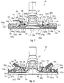
- Figs. 3a and 3b are used to describe forms of embodiment of the first bristle movement mechanism 12, which is configured to move the bristles of the first group of bristles 14a vertically.
- the first bristle movement mechanism 12 is shown in an activated position, that is, with the first group of bristles 14a lowered, while fig. 3b shows a de-activated position, or retraction position of the first group of bristles 14a.
- Figs. 4a and 4b are used to describe forms of embodiment of the second bristle movement mechanism 13, which is configured to move the bristles of the second group of bristles 14b vertically.
- the second bristle movement mechanism 13 is shown in an activated position, or lowered position of the second group of bristles 14b, while fig. 4b shows a de-activated position, or retracted position, of the second group of bristles 14b.
- the first bristle movement mechanism 12 can be connected to the first lever 16a and include a support frame 20a, to which the first group of bristles 14a is attached, a rocker arm 21a and a rod 22a which connects the first lever 16a and the rocker arm 21a.
- the first lever 16a is pivoted on the containing body 11, for example on its upper part 111, in correspondence with its rotation pin 23a, which defines a first axis of rotation X1 around which the first lever 16a rotates in order to make the first bristle movement mechanism 12 pass from the activated position to the de-activated one, and vice versa.
- the rocker arm 21a is provided with a pivoted end 121a, rotatably connected to the containing body 11, for example to its upper part 111, so as to define a second axis of rotation X2.
- the rod 22a can have a first end portion 122a, hinged to the first lever 16a in correspondence to a thrust segment 116a of the latter, and a second end portion 222a, opposite the first end portion 122a, hinged to a connection end 221a of the rocker arm 21a, opposite with respect to the pivoting end 121a of the latter.
- the rod 22a can be C-shaped and the end portions 122a and 222a can be two transverse branches of this conformation.
- the rod 22a is hinged to the first lever 16a by inserting its first end portion 122a in two through holes 24a (only one of which is visible in fig. 3a ) aligned along a first hinging axis Y1, parallel to the first axis of rotation X1.
- the through holes 24a act as first hinging means and are positioned at a first distance H1 from the rotation pin 23a.
- the first distance H1 defines the distance between the first axis of rotation X1 and the first hinging axis Y1.
- the rod 22a is hinged to the rocker arm 21a by inserting its second end portion 222a in a housing hole 25a made through in the connection end 221b of the rocker arm 21a.
- the housing hole 25a acts as second hinging means of the rod 22a along a second hinging axis Y2, parallel to the second axis of rotation X2 and located distanced from the latter at a second distance H2.
- first axis of rotation X1 and the second axis of rotation X2 can be parallel to each other.
- the first lever 16a, the rocker arm 21a and the rod 22a define a kinematism, that can be the articulated quadrilateral type, in which the first lever 16a and the rocker arm 21a are configured to rotate and pivot horizontally respectively around the first axis of rotation X1 and around the second axis of rotation X2, while the rod 22a is configured to translate or perform a roto-translation on a plane orthogonal to the axes of rotation X1, X2 and to the hinging axes Y1 and Y2.
- the first distance H1 can be equal to the second distance H2, and the consequent kinematism can be the articulated parallelogram type.
- the support frame 20a can include one or more guide blocks 26a, which can be defined by an inclined wall, or inclined plane 126a, and a positioning seating 226a, the latter positioned at one end of the inclined plane 126a.
- the frame 20a comprises four guide blocks 26a, one pair of which is positioned in proximity to the first lever 16a, and one pair positioned in proximity to the rocker arm 21a.
- the distance between the two pairs of guide blocks 26a is substantially equal to the length of the rod 22a.
- the guide blocks 26a are disposed so that the inclined planes 126a are all parallel to each other and that the positioning seatings 226a are all located at a same first height Q1 with respect to a base surface 120a of the frame 20a.
- the positioning seatings 226a can typically have a concave or convex shape, and in any case have a homologous shape with respect to the shape of the thrust segment 116a and of the connection end 221a of the rocker arm 21a.
- the thrust segment 116a rests on two corresponding positioning seatings 226a and is housed at least partly inside them.
- connection end 221a of the rocker arm 21a rests on the positioning seatings 226a of the other pair with respect to those on which the thrust segment 116a rests, and is housed at least partly inside them.
- the mating shape of the positioning seatings 226a with respect to the thrust segment 116a and to the connection end 221a allows a firm positioning, even if it is removable, of the first bristle movement mechanism 12 in its activated position.
- the thrust segment 116a and the connection end 221a can be in contact with the corresponding inclined planes 126a ( figs. 3b and 6 ), or can be completely released from the guide blocks 26a ( fig. 5 ).
- the passage of the bristle movement mechanism 12 from the activated position to the de-activated one, and vice versa, is determined by a rotation of the first lever 16a around the first axis of rotation X1.
- the first lever 16a performs a rotation in a clockwise direction with respect to the first axis of rotation X1, making the thrust segment 116a and the connection end 221b exit, in the first part of the clockwise rotation, from the respective positioning seatings 226a.
- the first lever 16a performs a rotation in an anti-clockwise direction with respect to the first axis of rotation X1.
- the first bristle movement mechanism 12 functions as follows, considering a de-activated initial position.
- the rotation of the first lever 16a around the first axis of rotation X1 determines an equal rotation of the thrust segment 116a, which thrusts the connection end 221a of the rocker arm 21a by means of the rod 22a.
- the horizontally pivoting angle of the rocker arm 21a is equal to the angle of rotation of the first lever 16a.
- the positioning of the guide blocks 26a is such that the rotation of the first lever 16a determines a corresponding sliding of the thrust segment 116a on the inclined planes 126a of the corresponding pair of guide blocks 26a. Moreover, the thrust of the rod 22a determines the corresponding sliding of the connection end 221a of the rocker arm 21a on the inclined planes 126a of the corresponding pair of guide blocks 26a.
- the corresponding sliding described above determines an absolute motion with respect to the upper part 111, downward, that is, away from the rotation pin 23a and from the pivoting end 121a, of the support frame 20a.
- the first group of bristles 14a descends, exiting from the brush bottom 211 when the first lever 16a is rotated in an anti-clockwise direction starting from the de-activated position.
- the second bristle movement mechanism 13 is completely analogous to the first bristle movement mechanism 12 and can include the second lever 16b, a support frame 20b, to which the second group of bristles 14b is attached, a rocker arm 21b and a rod 22b that connects the second lever 16b and the rocker arm 21b.
- the second lever 16b is pivoted on the containing body 11, for example on the upper part 111 of the latter, in correspondence to its rotation pin 23b, which defines a third axis of rotation X3 around which the second lever 16b rotates to make the bristle movement mechanism 13 pass from the activated position ( fig. 4a ) to the de-activated one ( fig. 4b ) and vice versa.
- the rod 22b has a first end portion 122b hinged to a thrust segment 116b of the second lever 16b and a second end portion 222b hinged to a connection end 221b of the rocker arm 21b.
- the end portions 122b and 222b are rotatable with respect to a third hinging axis Y3 and a fourth hinging axis Y4, respectively.
- the rocker arm 21b is pivoted to the containing body 11 of the brush 10, for example to its upper part 111, in correspondence to its pivoting end 121b, and is horizontally pivoting with respect thereto around a fourth axis of rotation X4.
- Third axis of rotation X3 and third hinging axis Y3 can be parallel to each other and located at a third distance H3.
- Fourth axis of rotation X4 and fourth hinging axis Y4 can be parallel to each other and located at a fourth distance H4.
- the third axis of rotation X3 and the fourth axis of rotation X4 can be parallel to each other.
- the third distance H3 and the fourth distance H4 can be equal.
- the axes of rotation X1, X2, X3, X4 can all be parallel to each other.
- the hinging axes Y1, Y2, Y3, Y4 can all be parallel to each other.
- the support frame 20b can include one or more guide blocks 26b, for example four, disposed in two pairs positioned one in proximity to the second lever 16b and one in proximity to the rocker arm 21b.
- the guide blocks 26b can each include an inclined plane 126b, on which the thrust segment 116b of the second lever 16b or the connection end 221b of the rocker arm 21b slides.
- Each guide block 26b can also include a positioning seating 226b, positioned at one end of the inclined plane 126b and configured to at least partly house the thrust segment 116b or the connection end 221b.
- the positioning seatings 226b are located at the same second height Q2 with respect to a base surface 120b of the support frame 20b.
- the second height Q2 is less than said first height Q1, which defines the distance of the positioning seatings 226a with respect to the base surface 120a.
- the functioning of the second bristle movement mechanism 13, analogous to that described above of the first bristle movement mechanism 12, provides that a rotation of the second lever 16b in a clockwise direction allows the passage of the second bristle movement mechanism 13 from the de-activated position ( fig. 4b ) to the activated position ( fig. 4a ) and vice versa.
- the thrust segment 116b moves along the inclined planes 126b of the corresponding guide blocks 26b to move, at the end of the rotation, into the positioning seatings 226b.
- connection end 221b of the latter slides in contact with the inclined planes 126b of the corresponding guide blocks 26b to position itself, at the end of the horizontal pivoting described above, in the positioning seatings 226b.
- the support frame 20b moves downward with respect to the containing body 11, that is, it moves away from the rotation pin 23b and from the pivoting end 121b, when the second bristle movement mechanism 13 passes from the de-activated position to the activated one.
- the support frame 20b moves upward with respect to the containing body 11, that is, it moves nearer the rotation pin 23b and to the pivoting end 121b, determining a corresponding vertical translatory motion of the second group of bristles 14b respectively exiting from the brush bottom 211 and retracting into the containing body 11.
- the support frame 20b of the second bristle movement mechanism 13 is positioned above the support frame 20a of the first bristle movement mechanism 12.
- Fig. 5 is used to describe forms of embodiment of the brush 10 in which it is in its first functioning condition.
- the first bristle movement mechanism 12 is in the de-activated position, while the second bristle movement mechanism 13 is in the activated position.
- the activation of the second bristle movement mechanism 13 makes the support frame 20b of the latter enter into contact with the support frame 20a of the first bristle movement mechanism 12, thrusting it downward.
- Fig. 6 is used to describe forms of embodiment of the brush 10 in which it is in its second functioning condition.
- both the first bristle movement mechanism 12 and the second bristle movement mechanism 13 are in the de-activated position.
- Fig. 7 is used to describe forms of embodiment of the brush 10 in which it is in its third functioning condition.
- the first bristle movement mechanism 12 is in the activated position, while the second bristle movement mechanism 13 is in the de-activated position.
- the bristles of the first group of bristles 14a protrude from the brush bottom 211 by about 4 mm.
- the first quantity L1 is equal to about 2.5 mm, that represents about 60% of the value of the second quantity L2, equal to 4 mm.
- Forms of embodiment can be provided in which the first quantity L1 and the second quantity L2 are equal.
- the first quantity L1 is greater than the second quantity L2.
- the second lever 16b can be provided with a prominent part 27, located in correspondence to the thrust segment 116b and protruding toward the central zone of the support frame 20b.
- the passage from the first functioning condition ( fig. 5 ) to the third functioning condition ( fig.7 ) of the brush 10, and vice versa, can occur directly due to the effect of the contact between the prominent part 27 and the connection end 221a of the rocker arm 21a of the first bristle movement mechanism 12.
- the second lever 16b is configured to make the second bristle movement mechanism 13 assume the activated position and at the same time make the first bristle movement mechanism 12 assume the de-activated position.
- first lever 16a can be configured to make the first bristle movement mechanism 12 assume the activated position and at the same time make the second bristle movement mechanism 13 assume the de-activated position.
- the second functioning condition ( fig. 6 ) can be obtained starting from any of the preceding first ( fig. 5 ) and third ( fig. 7 ) functioning conditions by activating the third lever 16c.
- the latter is pivoted to the containing body 11, for example to the upper part 111 of the latter, and is configured to rotate with respect to its axis of rotation Z, incident, for example substantially orthogonal, with respect to the axes of rotation X1 and X2, respectively of the first lever 16a and of the second lever 16b.
- the third lever 16c can be provided with a de-activation protuberance 28, configured to contact a front protrusion 29 of the first lever 16a and a rear projection 30 of the rocker arm 21b.
- the rear projection 30 is located below the de-activation protuberance 28.
- a rotation of the third lever 16c around its axis of rotation determines the contact between its de-activation protuberance 28 and the rear projection 30.
- This contact determines a rotation of the second lever 16b around the third axis of rotation X3, and consequently, by means of the rod 22b, a rotation of the rocker arm 21b around the fourth axis of rotation X4.
- both the second lever 16b and the rocker arm 21b are released from the positioning seatings 226b, allowing to lift the support frame 20a and with it the support frame 20b, with consequent passage of the second bristle movement mechanism 13 to the de-activated position and the brush 10 to the second functioning condition ( fig. 6 ).
- the front protrusion 29 is located below the de-activation protuberance 28.
- a rotation of the third lever 16c around its axis of rotation determines the contact between its de-activation protuberance 28 and the front protrusion 29. This contact determines a rotation of the first lever 16a around the first axis of rotation X1, and consequently, by means of the first rod 22a, of the rocker arm 21a around the second axis of rotation X2.
- both the first lever 16a and the rocker arm 21a are released from the positioning seatings 226a, with consequent passage of the first bristle movement mechanism 12 to the de-activated position and of the brush 10 to the second functioning condition ( fig. 6 ).
- the brush 10 can include elastic return means, such as for example one or more springs 31, helical, gas, cup or other type, configured to constantly exert an upward thrust against one or both support frames 20a, 20b.
- elastic return means such as for example one or more springs 31, helical, gas, cup or other type, configured to constantly exert an upward thrust against one or both support frames 20a, 20b.
- the springs 31 can perform the function of lifting one or both support frames 20a, 20b, even independently from each other, when the respective bristle movement mechanisms 12, 13 are de-activated.
- the springs 31 can perform the function of lifting the support frames 20a and 20b, when the third lever 16c is driven.
- Another function of the springs 31 is to maintain, by means of the thrust force, the thrust segments 116a, 116b and the connection ends 221a, 221b in the respective positioning seatings 226a, 226b when the first bristle movement mechanism 12 and/or the second bristle movement mechanism 13 are in the activated position.
- both a first pair of springs 31a acting on the support frame 20a, and a second pair of springs 31b acting on the support frame 20b are provided.
Landscapes
- Engineering & Computer Science (AREA)
- Mechanical Engineering (AREA)
- Nozzles For Electric Vacuum Cleaners (AREA)
- Brushes (AREA)
- Polishing Bodies And Polishing Tools (AREA)
Applications Claiming Priority (2)
| Application Number | Priority Date | Filing Date | Title |
|---|---|---|---|
| IT000115A ITUD20130115A1 (it) | 2013-09-03 | 2013-09-03 | Spazzola per apparecchiature di pulizia |
| PCT/IB2014/064225 WO2015033277A1 (en) | 2013-09-03 | 2014-09-03 | Brush for cleaning equipment |
Publications (2)
| Publication Number | Publication Date |
|---|---|
| EP3041394A1 EP3041394A1 (en) | 2016-07-13 |
| EP3041394B1 true EP3041394B1 (en) | 2017-11-01 |
Family
ID=49263393
Family Applications (1)
| Application Number | Title | Priority Date | Filing Date |
|---|---|---|---|
| EP14790313.2A Active EP3041394B1 (en) | 2013-09-03 | 2014-09-03 | Brush for cleaning equipment |
Country Status (4)
| Country | Link |
|---|---|
| EP (1) | EP3041394B1 (it) |
| CN (1) | CN105744870B (it) |
| IT (1) | ITUD20130115A1 (it) |
| WO (1) | WO2015033277A1 (it) |
Families Citing this family (1)
| Publication number | Priority date | Publication date | Assignee | Title |
|---|---|---|---|---|
| CN112057002A (zh) * | 2019-06-10 | 2020-12-11 | 康塔有限公司 | 地板清洁设备 |
Family Cites Families (5)
| Publication number | Priority date | Publication date | Assignee | Title |
|---|---|---|---|---|
| US2047677A (en) * | 1933-05-13 | 1936-07-14 | Electrolux Corp | Vacuum cleaner nozzle |
| KR960016448B1 (ko) * | 1994-12-15 | 1996-12-12 | 대우전자 주식회사 | 진공청소기의 보조 흡입구 |
| JP2005296621A (ja) * | 2004-04-13 | 2005-10-27 | Samsung Kwangju Electronics Co Ltd | 吸入ブラシ組立体およびこれを備えた真空掃除機 |
| DE102005041810A1 (de) * | 2005-09-02 | 2007-03-08 | BSH Bosch und Siemens Hausgeräte GmbH | Staubsaugerbodendüse mit Schaltvorrichtung |
| GB2470407A (en) * | 2009-05-22 | 2010-11-24 | Dyson Technology Ltd | Attachment for a vacuum cleaning appliance |
-
2013
- 2013-09-03 IT IT000115A patent/ITUD20130115A1/it unknown
-
2014
- 2014-09-03 CN CN201480060853.2A patent/CN105744870B/zh active Active
- 2014-09-03 WO PCT/IB2014/064225 patent/WO2015033277A1/en not_active Ceased
- 2014-09-03 EP EP14790313.2A patent/EP3041394B1/en active Active
Non-Patent Citations (1)
| Title |
|---|
| None * |
Also Published As
| Publication number | Publication date |
|---|---|
| ITUD20130115A1 (it) | 2015-03-04 |
| WO2015033277A1 (en) | 2015-03-12 |
| CN105744870A (zh) | 2016-07-06 |
| EP3041394A1 (en) | 2016-07-13 |
| CN105744870B (zh) | 2018-03-09 |
Similar Documents
| Publication | Publication Date | Title |
|---|---|---|
| CN104068792B (zh) | 吸尘器地刷及其吸尘器 | |
| EP2453780B1 (en) | A surface treating head | |
| CN104159487B (zh) | 真空吸尘器地面密封物 | |
| GB2453618A (en) | Nozzle unit for a vacuum cleaner | |
| EP2946713A1 (en) | Floor scrubbing machine | |
| JP2014524270A (ja) | 駆動可能な床洗浄機、及び床洗浄機を作動するための方法 | |
| AU2010272317A1 (en) | A surface treating head | |
| EP2453778B1 (en) | A surface treating head | |
| CN105455730A (zh) | 地板吸尘器的吸嘴 | |
| AU2021232679B2 (en) | Cleaning apparatus with combing unit for removing debris from cleaning roller | |
| KR101777177B1 (ko) | 운동화 세척장치 | |
| US8510908B2 (en) | Surface treating head assembly | |
| EP3041394B1 (en) | Brush for cleaning equipment | |
| US7895706B2 (en) | Surface treating head assembly | |
| CN112499328A (zh) | 一种地毯用收起装置 | |
| EP3096665A1 (en) | A head for a surface cleaning device | |
| US8132288B2 (en) | Surface treating head assembly | |
| GB2471920A (en) | A surface treating head | |
| CN207576997U (zh) | 一种椅子生产用的除尘设备 | |
| EP3151711B1 (en) | Nozzle with three settings | |
| ITPN20070041A1 (it) | "apparecchio aspiratore di tipo versatile per la pulizia di superfici di varia natura e durezza" | |
| KR101724153B1 (ko) | 걸레청소용 로봇청소기 | |
| CN101252867A (zh) | 包括可控制的毛刷的吸尘器地板吸嘴 | |
| GB2471919A (en) | A surface treating head | |
| KR20210034964A (ko) | 침대 청소기 |
Legal Events
| Date | Code | Title | Description |
|---|---|---|---|
| PUAI | Public reference made under article 153(3) epc to a published international application that has entered the european phase |
Free format text: ORIGINAL CODE: 0009012 |
|
| 17P | Request for examination filed |
Effective date: 20160330 |
|
| AK | Designated contracting states |
Kind code of ref document: A1 Designated state(s): AL AT BE BG CH CY CZ DE DK EE ES FI FR GB GR HR HU IE IS IT LI LT LU LV MC MK MT NL NO PL PT RO RS SE SI SK SM TR |
|
| AX | Request for extension of the european patent |
Extension state: BA ME |
|
| DAX | Request for extension of the european patent (deleted) | ||
| GRAP | Despatch of communication of intention to grant a patent |
Free format text: ORIGINAL CODE: EPIDOSNIGR1 |
|
| INTG | Intention to grant announced |
Effective date: 20170509 |
|
| GRAS | Grant fee paid |
Free format text: ORIGINAL CODE: EPIDOSNIGR3 |
|
| GRAA | (expected) grant |
Free format text: ORIGINAL CODE: 0009210 |
|
| AK | Designated contracting states |
Kind code of ref document: B1 Designated state(s): AL AT BE BG CH CY CZ DE DK EE ES FI FR GB GR HR HU IE IS IT LI LT LU LV MC MK MT NL NO PL PT RO RS SE SI SK SM TR |
|
| REG | Reference to a national code |
Ref country code: GB Ref legal event code: FG4D |
|
| REG | Reference to a national code |
Ref country code: CH Ref legal event code: EP Ref country code: AT Ref legal event code: REF Ref document number: 941152 Country of ref document: AT Kind code of ref document: T Effective date: 20171115 |
|
| REG | Reference to a national code |
Ref country code: IE Ref legal event code: FG4D |
|
| REG | Reference to a national code |
Ref country code: DE Ref legal event code: R096 Ref document number: 602014016699 Country of ref document: DE |
|
| REG | Reference to a national code |
Ref country code: NL Ref legal event code: MP Effective date: 20171101 |
|
| REG | Reference to a national code |
Ref country code: LT Ref legal event code: MG4D |
|
| REG | Reference to a national code |
Ref country code: AT Ref legal event code: MK05 Ref document number: 941152 Country of ref document: AT Kind code of ref document: T Effective date: 20171101 |
|
| PG25 | Lapsed in a contracting state [announced via postgrant information from national office to epo] |
Ref country code: ES Free format text: LAPSE BECAUSE OF FAILURE TO SUBMIT A TRANSLATION OF THE DESCRIPTION OR TO PAY THE FEE WITHIN THE PRESCRIBED TIME-LIMIT Effective date: 20171101 Ref country code: NL Free format text: LAPSE BECAUSE OF FAILURE TO SUBMIT A TRANSLATION OF THE DESCRIPTION OR TO PAY THE FEE WITHIN THE PRESCRIBED TIME-LIMIT Effective date: 20171101 Ref country code: NO Free format text: LAPSE BECAUSE OF FAILURE TO SUBMIT A TRANSLATION OF THE DESCRIPTION OR TO PAY THE FEE WITHIN THE PRESCRIBED TIME-LIMIT Effective date: 20180201 Ref country code: SE Free format text: LAPSE BECAUSE OF FAILURE TO SUBMIT A TRANSLATION OF THE DESCRIPTION OR TO PAY THE FEE WITHIN THE PRESCRIBED TIME-LIMIT Effective date: 20171101 Ref country code: LT Free format text: LAPSE BECAUSE OF FAILURE TO SUBMIT A TRANSLATION OF THE DESCRIPTION OR TO PAY THE FEE WITHIN THE PRESCRIBED TIME-LIMIT Effective date: 20171101 Ref country code: FI Free format text: LAPSE BECAUSE OF FAILURE TO SUBMIT A TRANSLATION OF THE DESCRIPTION OR TO PAY THE FEE WITHIN THE PRESCRIBED TIME-LIMIT Effective date: 20171101 |
|
| PG25 | Lapsed in a contracting state [announced via postgrant information from national office to epo] |
Ref country code: AT Free format text: LAPSE BECAUSE OF FAILURE TO SUBMIT A TRANSLATION OF THE DESCRIPTION OR TO PAY THE FEE WITHIN THE PRESCRIBED TIME-LIMIT Effective date: 20171101 Ref country code: RS Free format text: LAPSE BECAUSE OF FAILURE TO SUBMIT A TRANSLATION OF THE DESCRIPTION OR TO PAY THE FEE WITHIN THE PRESCRIBED TIME-LIMIT Effective date: 20171101 Ref country code: BG Free format text: LAPSE BECAUSE OF FAILURE TO SUBMIT A TRANSLATION OF THE DESCRIPTION OR TO PAY THE FEE WITHIN THE PRESCRIBED TIME-LIMIT Effective date: 20180201 Ref country code: LV Free format text: LAPSE BECAUSE OF FAILURE TO SUBMIT A TRANSLATION OF THE DESCRIPTION OR TO PAY THE FEE WITHIN THE PRESCRIBED TIME-LIMIT Effective date: 20171101 Ref country code: HR Free format text: LAPSE BECAUSE OF FAILURE TO SUBMIT A TRANSLATION OF THE DESCRIPTION OR TO PAY THE FEE WITHIN THE PRESCRIBED TIME-LIMIT Effective date: 20171101 Ref country code: IS Free format text: LAPSE BECAUSE OF FAILURE TO SUBMIT A TRANSLATION OF THE DESCRIPTION OR TO PAY THE FEE WITHIN THE PRESCRIBED TIME-LIMIT Effective date: 20180301 Ref country code: GR Free format text: LAPSE BECAUSE OF FAILURE TO SUBMIT A TRANSLATION OF THE DESCRIPTION OR TO PAY THE FEE WITHIN THE PRESCRIBED TIME-LIMIT Effective date: 20180202 |
|
| PG25 | Lapsed in a contracting state [announced via postgrant information from national office to epo] |
Ref country code: CZ Free format text: LAPSE BECAUSE OF FAILURE TO SUBMIT A TRANSLATION OF THE DESCRIPTION OR TO PAY THE FEE WITHIN THE PRESCRIBED TIME-LIMIT Effective date: 20171101 Ref country code: DK Free format text: LAPSE BECAUSE OF FAILURE TO SUBMIT A TRANSLATION OF THE DESCRIPTION OR TO PAY THE FEE WITHIN THE PRESCRIBED TIME-LIMIT Effective date: 20171101 Ref country code: EE Free format text: LAPSE BECAUSE OF FAILURE TO SUBMIT A TRANSLATION OF THE DESCRIPTION OR TO PAY THE FEE WITHIN THE PRESCRIBED TIME-LIMIT Effective date: 20171101 Ref country code: CY Free format text: LAPSE BECAUSE OF FAILURE TO SUBMIT A TRANSLATION OF THE DESCRIPTION OR TO PAY THE FEE WITHIN THE PRESCRIBED TIME-LIMIT Effective date: 20171101 Ref country code: SK Free format text: LAPSE BECAUSE OF FAILURE TO SUBMIT A TRANSLATION OF THE DESCRIPTION OR TO PAY THE FEE WITHIN THE PRESCRIBED TIME-LIMIT Effective date: 20171101 |
|
| REG | Reference to a national code |
Ref country code: DE Ref legal event code: R097 Ref document number: 602014016699 Country of ref document: DE |
|
| PG25 | Lapsed in a contracting state [announced via postgrant information from national office to epo] |
Ref country code: RO Free format text: LAPSE BECAUSE OF FAILURE TO SUBMIT A TRANSLATION OF THE DESCRIPTION OR TO PAY THE FEE WITHIN THE PRESCRIBED TIME-LIMIT Effective date: 20171101 Ref country code: SM Free format text: LAPSE BECAUSE OF FAILURE TO SUBMIT A TRANSLATION OF THE DESCRIPTION OR TO PAY THE FEE WITHIN THE PRESCRIBED TIME-LIMIT Effective date: 20171101 Ref country code: PL Free format text: LAPSE BECAUSE OF FAILURE TO SUBMIT A TRANSLATION OF THE DESCRIPTION OR TO PAY THE FEE WITHIN THE PRESCRIBED TIME-LIMIT Effective date: 20171101 |
|
| REG | Reference to a national code |
Ref country code: FR Ref legal event code: PLFP Year of fee payment: 5 |
|
| PLBE | No opposition filed within time limit |
Free format text: ORIGINAL CODE: 0009261 |
|
| STAA | Information on the status of an ep patent application or granted ep patent |
Free format text: STATUS: NO OPPOSITION FILED WITHIN TIME LIMIT |
|
| 26N | No opposition filed |
Effective date: 20180802 |
|
| PG25 | Lapsed in a contracting state [announced via postgrant information from national office to epo] |
Ref country code: SI Free format text: LAPSE BECAUSE OF FAILURE TO SUBMIT A TRANSLATION OF THE DESCRIPTION OR TO PAY THE FEE WITHIN THE PRESCRIBED TIME-LIMIT Effective date: 20171101 |
|
| PG25 | Lapsed in a contracting state [announced via postgrant information from national office to epo] |
Ref country code: MC Free format text: LAPSE BECAUSE OF FAILURE TO SUBMIT A TRANSLATION OF THE DESCRIPTION OR TO PAY THE FEE WITHIN THE PRESCRIBED TIME-LIMIT Effective date: 20171101 |
|
| REG | Reference to a national code |
Ref country code: CH Ref legal event code: PL |
|
| REG | Reference to a national code |
Ref country code: BE Ref legal event code: MM Effective date: 20180930 |
|
| REG | Reference to a national code |
Ref country code: IE Ref legal event code: MM4A |
|
| PG25 | Lapsed in a contracting state [announced via postgrant information from national office to epo] |
Ref country code: LU Free format text: LAPSE BECAUSE OF NON-PAYMENT OF DUE FEES Effective date: 20180903 |
|
| PG25 | Lapsed in a contracting state [announced via postgrant information from national office to epo] |
Ref country code: IE Free format text: LAPSE BECAUSE OF NON-PAYMENT OF DUE FEES Effective date: 20180903 |
|
| PG25 | Lapsed in a contracting state [announced via postgrant information from national office to epo] |
Ref country code: LI Free format text: LAPSE BECAUSE OF NON-PAYMENT OF DUE FEES Effective date: 20180930 Ref country code: CH Free format text: LAPSE BECAUSE OF NON-PAYMENT OF DUE FEES Effective date: 20180930 Ref country code: BE Free format text: LAPSE BECAUSE OF NON-PAYMENT OF DUE FEES Effective date: 20180930 |
|
| PG25 | Lapsed in a contracting state [announced via postgrant information from national office to epo] |
Ref country code: MT Free format text: LAPSE BECAUSE OF NON-PAYMENT OF DUE FEES Effective date: 20180903 |
|
| PG25 | Lapsed in a contracting state [announced via postgrant information from national office to epo] |
Ref country code: TR Free format text: LAPSE BECAUSE OF FAILURE TO SUBMIT A TRANSLATION OF THE DESCRIPTION OR TO PAY THE FEE WITHIN THE PRESCRIBED TIME-LIMIT Effective date: 20171101 |
|
| PG25 | Lapsed in a contracting state [announced via postgrant information from national office to epo] |
Ref country code: PT Free format text: LAPSE BECAUSE OF FAILURE TO SUBMIT A TRANSLATION OF THE DESCRIPTION OR TO PAY THE FEE WITHIN THE PRESCRIBED TIME-LIMIT Effective date: 20171101 |
|
| PG25 | Lapsed in a contracting state [announced via postgrant information from national office to epo] |
Ref country code: MK Free format text: LAPSE BECAUSE OF NON-PAYMENT OF DUE FEES Effective date: 20171101 Ref country code: HU Free format text: LAPSE BECAUSE OF FAILURE TO SUBMIT A TRANSLATION OF THE DESCRIPTION OR TO PAY THE FEE WITHIN THE PRESCRIBED TIME-LIMIT; INVALID AB INITIO Effective date: 20140903 |
|
| PG25 | Lapsed in a contracting state [announced via postgrant information from national office to epo] |
Ref country code: AL Free format text: LAPSE BECAUSE OF FAILURE TO SUBMIT A TRANSLATION OF THE DESCRIPTION OR TO PAY THE FEE WITHIN THE PRESCRIBED TIME-LIMIT Effective date: 20171101 |
|
| PGFP | Annual fee paid to national office [announced via postgrant information from national office to epo] |
Ref country code: FR Payment date: 20210909 Year of fee payment: 8 |
|
| PGFP | Annual fee paid to national office [announced via postgrant information from national office to epo] |
Ref country code: GB Payment date: 20210910 Year of fee payment: 8 |
|
| PGFP | Annual fee paid to national office [announced via postgrant information from national office to epo] |
Ref country code: DE Payment date: 20220907 Year of fee payment: 9 |
|
| GBPC | Gb: european patent ceased through non-payment of renewal fee |
Effective date: 20220903 |
|
| P01 | Opt-out of the competence of the unified patent court (upc) registered |
Effective date: 20230513 |
|
| PG25 | Lapsed in a contracting state [announced via postgrant information from national office to epo] |
Ref country code: FR Free format text: LAPSE BECAUSE OF NON-PAYMENT OF DUE FEES Effective date: 20220930 |
|
| PG25 | Lapsed in a contracting state [announced via postgrant information from national office to epo] |
Ref country code: GB Free format text: LAPSE BECAUSE OF NON-PAYMENT OF DUE FEES Effective date: 20220903 |
|
| REG | Reference to a national code |
Ref country code: DE Ref legal event code: R119 Ref document number: 602014016699 Country of ref document: DE |
|
| PG25 | Lapsed in a contracting state [announced via postgrant information from national office to epo] |
Ref country code: DE Free format text: LAPSE BECAUSE OF NON-PAYMENT OF DUE FEES Effective date: 20240403 |
|
| PGFP | Annual fee paid to national office [announced via postgrant information from national office to epo] |
Ref country code: IT Payment date: 20240912 Year of fee payment: 11 |