EP3041441B1 - Orthese de main pour le maintien du pouce notamment en cas de rhizarthrose - Google Patents
Orthese de main pour le maintien du pouce notamment en cas de rhizarthrose Download PDFInfo
- Publication number
- EP3041441B1 EP3041441B1 EP14759021.0A EP14759021A EP3041441B1 EP 3041441 B1 EP3041441 B1 EP 3041441B1 EP 14759021 A EP14759021 A EP 14759021A EP 3041441 B1 EP3041441 B1 EP 3041441B1
- Authority
- EP
- European Patent Office
- Prior art keywords
- thumb
- hand
- orthosis
- orthosis according
- main part
- Prior art date
- Legal status (The legal status is an assumption and is not a legal conclusion. Google has not performed a legal analysis and makes no representation as to the accuracy of the status listed.)
- Active
Links
Images


Classifications
-
- A—HUMAN NECESSITIES
- A61—MEDICAL OR VETERINARY SCIENCE; HYGIENE
- A61F—FILTERS IMPLANTABLE INTO BLOOD VESSELS; PROSTHESES; DEVICES PROVIDING PATENCY TO, OR PREVENTING COLLAPSING OF, TUBULAR STRUCTURES OF THE BODY, e.g. STENTS; ORTHOPAEDIC, NURSING OR CONTRACEPTIVE DEVICES; FOMENTATION; TREATMENT OR PROTECTION OF EYES OR EARS; BANDAGES, DRESSINGS OR ABSORBENT PADS; FIRST-AID KITS
- A61F5/00—Orthopaedic methods or devices for non-surgical treatment of bones or joints; Nursing devices ; Anti-rape devices
- A61F5/01—Orthopaedic devices, e.g. long-term immobilising or pressure directing devices for treating broken or deformed bones such as splints, casts or braces
- A61F5/0102—Orthopaedic devices, e.g. long-term immobilising or pressure directing devices for treating broken or deformed bones such as splints, casts or braces specially adapted for correcting deformities of the limbs or for supporting them; Ortheses, e.g. with articulations
- A61F5/0104—Orthopaedic devices, e.g. long-term immobilising or pressure directing devices for treating broken or deformed bones such as splints, casts or braces specially adapted for correcting deformities of the limbs or for supporting them; Ortheses, e.g. with articulations without articulation
- A61F5/0118—Orthopaedic devices, e.g. long-term immobilising or pressure directing devices for treating broken or deformed bones such as splints, casts or braces specially adapted for correcting deformities of the limbs or for supporting them; Ortheses, e.g. with articulations without articulation for the arms, hands or fingers
-
- A—HUMAN NECESSITIES
- A61—MEDICAL OR VETERINARY SCIENCE; HYGIENE
- A61F—FILTERS IMPLANTABLE INTO BLOOD VESSELS; PROSTHESES; DEVICES PROVIDING PATENCY TO, OR PREVENTING COLLAPSING OF, TUBULAR STRUCTURES OF THE BODY, e.g. STENTS; ORTHOPAEDIC, NURSING OR CONTRACEPTIVE DEVICES; FOMENTATION; TREATMENT OR PROTECTION OF EYES OR EARS; BANDAGES, DRESSINGS OR ABSORBENT PADS; FIRST-AID KITS
- A61F5/00—Orthopaedic methods or devices for non-surgical treatment of bones or joints; Nursing devices ; Anti-rape devices
- A61F5/01—Orthopaedic devices, e.g. long-term immobilising or pressure directing devices for treating broken or deformed bones such as splints, casts or braces
- A61F5/30—Pressure pads
- A61F5/34—Pressure pads filled with air or liquid
Definitions
- the present invention relates to a thumb orthosis.
- the present invention aims in particular to relieve people suffering from rhizarthrosis.
- Rhizarthrosis is usually treated with drugs and / or orthopedic accessories. Some of these accessories are in the form of rigid orthoses to completely immobilize the joint in question. These orthoses are worn mainly at night. By immobilizing the joint, they suppress the pain when the joint is in crisis. They also avoid some fatigue of the joint by preventing involuntary movements.
- the document FR2822371 discloses a hand orthosis comprising a main piece made of an elastic material and having a first sleeve-shaped portion fitted to a portion of the thumb extending to the fold zone between the thumb and the palm of the hand, a second sleeve-shaped portion fitted to the wrist, and a third portion connecting the first and second portions, shaped to enclose an area of the hand extending along the metacarpal of the thumb between the back and the palm of the hand, and comprising an opening for the passage of the palm of the hand.
- Embodiments relate to a hand orthosis for holding the thumb, the orthosis comprising a main piece made of an elastic material and having: a first sleeve-shaped portion fitted to a portion of the thumb extending to the crease zone between the thumb and palm of the hand, a wrist-shaped second sleeve portion, and a third portion connecting the first and second portions, shaped to enclose an area of the hand extending along the metacarpal of the thumb between the back and the palm of the hand, and having an opening for the passage of the palm of the hand.
- the second part is assembled by a seam line to take the form of a sleeve, and the main part is shaped so as not to not covering the fold zone between the thumb and the palm of the hand and is made of a material having in a direction corresponding to a longitudinal axis of the first part a Young's modulus between 0.5 MPa and 1 MPa.
- the first part is shaped to cover the articulation between the two phalanges of the thumb.
- the main piece comprises two layers of elastic fabric assembled by gluing.
- each of the two layers is made of a fabric comprising between 75 and 85% by weight of polyamide and between 15 and 25% by weight of elastane.
- each of the two layers has a basis weight of 155 g / m 2, and / or a thickness of between 0.5 and 0.7 mm.
- each of the two layers has an elasticity of 85% to 115% in the direction of the warp and 65% to 95% in the weft direction.
- the orthosis comprises a plate made of a material capable of providing a damping function, the plate being fixed inside the second and third parts in an area covering the articulation between the metacarpal of the thumb and wrist.
- the wafer is made of a crosslinked polymer gel.
- the wafer has a thickness of between 0.4 and 1 mm.
- the wafer is adhered to a resilient fabric cover which is assembled with the main piece by a seam so that the wafer is sandwiched between the main piece and the cover piece.
- the plate is sewn with the covering part on the main part.
- the main piece is adjusted by hand and thumb to hold the thumb joints in a hand configuration where all the muscles of the hand are released and in the absence of external forces acting on the hand. the joints of the thumb.
- the main piece is made of a material having a thickness of between 1 mm and 1.4 mm.
- FIGS. 1A, 1B, 1C represent the carpo-metacarpal joints of the thumb and index finger.
- the carpo-metacarpal joints of the MSA thumb comprise an articulation between the metacarpus MP and the trapezium TZ, and a joint between on the one hand the scaphoid SC, and on the other hand, the trapezium TZ and the trapezoid TD.
- the carpo-metacarpal joints of the index include a joint between the metacarp MI of the index and the trapezoid TD and a joint between the trapezoid TD and scaphoid SC.
- Osteoarthritis can affect one and / or the other of the MSA joints, marked by hatching on the Figures 1A and 1B .
- the thumb can also be affected by a subluxation of the MP metacarp with respect to the TZ trapezium, as shown in figure 1C .
- the Figures 2 to 4 and 6 represent an orthosis of thumb, according to one embodiment, for relieving persons suffering from rhizarthrosis or subluxation of the metacarpal of the thumb.
- the figures 2 and 6 represent the orthosis placed on a hand.
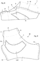
- the figures 3 and 4 respectively represent a portion of the outer face and the inner face of the orthosis.
- the orthosis comprises a main part 1 forming a distal portion 2, a proximal portion 4, and an intermediate portion 3 connecting the parts 2 and 4, delimited on the Figures 2 to 4 by dotted lines and dashes.
- the sleeve-shaped portion 2 is shaped to cover and hold the thumb of the crease zone between the thumb and the palm of the hand at the inter-phalangeal joint of the thumb.
- Part 2 may extend for example to the vicinity of the middle of the distal phalanx of the thumb.
- the Part 4 also in the form of a sleeve, is shaped to cover part of the forearm, the wrist, the carpo-metacarpal joints of the thumb, and a proximal portion of the metacarpus fingers.
- the intermediate portion 3 has an opening 6 extending between the parts 2 and 3, for the passage of the palm of the hand.
- the main piece 1 is made of an elastic material and adjusted to the shape of the hand and thumb to maintain, without exerting too much force of restraint, likely to cause pain, especially in the sensitive area of the carp joints. metacarpal MSA.
- the orthosis can be removed towards the ends of the fingers and the thumb, without significant effort, especially because of the absence of throttling zones.
- the material forming the part 1 has a certain rigidity which combines with a beam effect imparted by the tubular or semi-tubular shape with curved straight section of the orthosis.
- the resulting stiffness of the material and the beam effect makes the orthosis susceptible to supporting the weight of the thumb without sagging.
- the material forming Part 1 has a Young's modulus between 0.5 MPa and 1 MPa, for example substantially equal to 0.7 MPa.
- the beam effect obtained can be characterized by the quadratic moment. This moment is about 3000 mm4 for the sleeve of inch 2, and about half for the intermediate part 3.
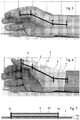
- the ability of the orthosis to support the weight of the thumb is illustrated by the Figures 5 and 6 .
- the Figures 5 and 6 represent the inner face of a hand placed on its edge on a horizontal plane, the muscles of hand being released.
- the axes of the forearm, metacarpal of the thumb and proximal phalanx of the thumb are respectively marked by segments [A, B], [B, C] and [C, D].
- the carpal metacarpal joints MSA and metacarpophalangeal thumb are identified by the points B and C. In the configuration of the hand shown on the figure 5 , it appears that the joints B and C are bent under the effect of the weight of the thumb. The thumb is thus substantially below the level of the index finger of the hand on the figure 5 .
- the hand is in the same configuration as on the figure 5 but is equipped with the orthosis. It appears on the figure 6 that the thumb is one level above the index of the hand.
- the angle ABC appears slightly smaller on the figure 6 that on the figure 5 .
- the BCD angle appears significantly larger (about twenty degrees) on the figure 6 that on the figure 5 .
- the joints B and C of the thumb do not undergo involuntary movements, for example during changes of orientation of the hand relative to gravity, or related to the laws of kinematics.
- This rigidity also makes it possible to reduce the amplitude and duration of involuntary movements such as reflex movements.
- the elasticity of the material forming Part 1 allows the orthosis not to hinder the voluntary movements of the thumb, and thus avoids having to exert significant additional efforts on the diseased joint during such voluntary movements. The user can seize an object with his hand by exerting a minimum additional effort to compensate for the stiffness of the orthosis.
- the orthosis does not cover the crease area between the thumb and the palm of the hand and therefore does not interfere with the pincer function of the hand. Note also that the support effect conferred by the orthosis extends to the metacarpophalangeal joint C of the thumb, this joint can also suffer from osteoarthritis.
- the material in which the piece 1 is formed is made using two layers of an elastic fabric, glued to one another, by a glue layer of about 0, 05 mm thick.
- the adhesive layer may be uniformly distributed between the two layers of fabric, or arranged in uniformly distributed spots.
- the two layers of fabric can be glued together by gluing one of the two layers, and pressing the two layers against each other by means of one or two rollers.
- the fabric forming the two layers may be a polyamide-based fabric (about 80% by weight) and elastane (about 20% by weight), having a basis weight of 155 g / m 2.
- the glue used may be based on polyurethane.
- the entire material formed by the two thicknesses of fabric and the adhesive layer may have a basis weight of 355 g / m 2.
- the fabric forming the two layers may have a thickness of between 0.5 and 0.7 mm.
- the material in which the workpiece 1 is formed may have a thickness of between 1 and 1.4 mm.
- This fabric may have an elasticity of between 85% to 115% in the warp direction and 65% to 95% in the weft direction.
- the orthosis comprises a damping element 5 which also has a certain intrinsic stiffness.
- the damping element 5 has a suitable shape and is arranged on the main part 1 so as to cover the carpo-metacarpal joints of the thumb.
- the damping element has substantially the shape of a crescent whose tips are truncated ( figure 8 ).
- the damping element comprises a wafer 5 made of a viscoelastic material, such as a crosslinked polymer gel, for example a non-adhesive crosslinked silicone gel, which is fixed on the inner face of the part 1.
- a viscoelastic material such as a crosslinked polymer gel, for example a non-adhesive crosslinked silicone gel
- the figure 7 represents a part of the orthosis on which is fixed the plate 5.
- the wafer 5 can be glued to a piece of tissue 52 which is fixed on the inner face of the main part 1 of the orthosis by seams 51, the wafer 5 being sandwiched between the main piece 1 and the piece of 52.
- the figure 7 also shows the two layers 1a, 1b forming the main part 1.
- the main part 1 can be made in one piece 10, some edges are assembled to form the orthosis.
- the figure 8 represents the piece 10 flat, comprising the parts 2, 3, 4.
- the parts 2 and 4 have substantially the shape of a slightly curved band, with a seam line 21, 41 at each end.
- the lines 21 are intended to be secured to each other to form the thumb sleeve 2.
- the lines 41 are attached to each other to form the palm sleeve 4.
- the portion 3 has a trapezoidal shape without seam line.
- the figure 8 also represents the plate 5, most of which is fixed on the part 4, and the remaining parts on the part 3, before the seams 21, 41 are made.
- the piece 10 can be used indifferently for making right and left hand orthoses.
- the hand for which the orthosis is intended is determined by the face on which the plate 5 is fixed.
- the part 10 represented on the figure 8 is intended to achieve a orthosis of left hand.
- the seams 21 and 41 are made by folding the piece 10 towards the external face of the orthosis so as to superimpose the lines 21 to form the sleeve 2, and to superimpose the lines 41 to form the sleeve 4.
- the Figures 9A and 9B represent curves C1, C2, C3, C4 illustrating the performance of the orthosis.
- Curves C1 to C4 show the time variations of the angle ABC formed by the carpo-metacarpal joints of the thumb during a fall on a horizontal plane of the hand, muscles relaxed.
- Curves C1 and C3 correspond to a fall of 5 cm, and curves C2 and C4, a fall of 10 cm.
- C1 and C2 curves on the Figure 9A illustrate the case where the hand does not wear an orthosis and the curves C3 and C4 on the Figure 9B illustrate the case where the hand is wearing the orthosis as shown on the Figures 2 to 4 and 6 .
- the angle ABC reaches a peak at about 167 ° as a result of the shock at the instant 0.22 s, then oscillates between 154 ° and 161 ° in a damped manner.
- the angle ABC reaches a peak at about 173 ° after the shock at the instant 0.25 s, then oscillates between 150 ° and 162 ° in a damped manner.
- the peak reached by the angle ABC is limited to about 157 ° (instead of 163 °) following the shock at the instant 0.21 s, then oscillates between 148 ° and 152 ° in a cushioned way.
- the peak attained by the angle ABC is limited to about 158 ° (instead of 173 °) following the shock at the instant 0.22 s, then oscillates between 146 ° and 152 ° in a cushioned way.
- the curves C1 to C4 show that the movements of the thumb around the MSA joint, resulting from the shock, have amplitudes attenuated thanks to the orthosis. It can also be observed that the oscillations resulting from the shock last less with the orthosis.
- the present invention is capable of various alternative embodiments and various applications.
- the invention is not limited to an orthosis comprising a damping pad.
- the orthosis without the plate ensures perfectly the function of maintaining the carpo-metacarpal joints of the thumb of the joint.
- the oscillations observed on the Figure 9B have lower amplitudes than on the Figure 9A these oscillations also last less.
- the thumb sleeve Neither is it necessary for the thumb sleeve to cover the distal thumb joint. Indeed, the maintenance of the carpo-metacarpal joints is perfectly assured when the orthosis covers the thumb only up to half of the proximal phalanx. Moreover, since the orthosis is made in only a few standard sizes and not made to measure, the part of the thumb covered by the orthosis depends on the morphologies.
Landscapes
- Health & Medical Sciences (AREA)
- Nursing (AREA)
- Orthopedic Medicine & Surgery (AREA)
- Engineering & Computer Science (AREA)
- Biomedical Technology (AREA)
- Heart & Thoracic Surgery (AREA)
- Vascular Medicine (AREA)
- Life Sciences & Earth Sciences (AREA)
- Animal Behavior & Ethology (AREA)
- General Health & Medical Sciences (AREA)
- Public Health (AREA)
- Veterinary Medicine (AREA)
- Orthopedics, Nursing, And Contraception (AREA)
- Professional, Industrial, Or Sporting Protective Garments (AREA)
Description
- La présente invention concerne une orthèse de pouce. La présente invention vise notamment à soulager les personnes souffrant de rhizarthrose.
- Avec l'âge, un grand nombre de personnes souffrent d'arthrose, en particulier de l'articulation entre le pouce et le poignet. Cette affection appelée "rhizarthrose", touche principalement les femmes, et se manifeste par poussées très douloureuses. La nuit, des mouvements aléatoires du pouce peuvent entrainer des douleurs au point de priver de sommeil. Cette affection peut concerner l'articulation entre le trapèze et le métacarpe du pouce et/ou l'articulation entre le scaphoïde et le trapèze et le trapézoïde. Cette affection peut également se traduire par une instabilité ou une subluxation de l'articulation entre le trapèze et le métacarpe du pouce.
- La rhizarthrose est généralement traitée par des médicaments et/ou par des accessoires d'orthopédie. Certains de ces accessoires se présentent sous la forme d'orthèses rigides visant à immobiliser totalement l'articulation en cause. Ces orthèses sont donc portées principalement la nuit. En immobilisant l'articulation, elles suppriment la douleur lorsque l'articulation est en crise. Elles évitent également une certaine fatigue de l'articulation en empêchant des mouvements involontaires.
- Le principal inconvénient de ces orthèses réside dans leur rigidité qui empêche un usage normal du pouce et en particulier de la fonction essentielle de la main qu'est la fonction de pince. Ces orthèses présentent également l'inconvénient de devoir être réalisées sur mesure, par exemple par thermoformage sur la main.
- Il existe également des orthèses élastiques visant également à immobiliser l'articulation. Or il s'avère que la fonction de pince de la main produit une importante démultiplication des efforts dans la chaine articulaire entre le pouce et le poignet. Ainsi, la force exercée par la pince est multipliée par un facteur de douze sur l'articulation carpo-métacarpienne. Il en résulte que ces orthèses doivent appliquer une forte pression de contention à la base du poignet, notamment pour contenir les mouvements liés à une éventuelle subluxation de l'articulation. Ces orthèses doivent donc être également réalisées sur mesure.
- Par ailleurs, il existe des orthèses se présentant sous la forme d'un gantelet, également réalisé sur mesure par thermoformage sur la main.
- Toutes les orthèses précédemment décrites présentent les inconvénients non seulement de devoir être réalisées sur mesure, mais également de couvrir le pli entre le pouce et la paume. Il en résulte que seule l'articulation interphalangienne du pouce n'est pas bloquée.
- Les documents
US6702772 etUS2003/0191421 décrivent des orthèses de main pour le maintien du pouce telles que décrites ci-dessus. - Le document
FR2822371 - Il est souhaitable de réaliser une orthèse de pouce apte à soulager l'articulation carpo-métacarpienne, mais sans entraver la fonction de pince de la main. Il est également souhaitable de réaliser une orthèse de pouce qui ne nécessite pas d'être réalisée sur mesure, mais seulement en quelques tailles standard, sans nécessiter d'ajustement final.
- Des modes de réalisation concernent une orthèse de main pour le maintien du pouce, l'orthèse comprenant une pièce principale réalisée en un matériau élastique et comportant : une première partie en forme de manchon ajustée à une partie du pouce s'étendant jusqu'à la zone de pli entre le pouce et la paume de la main, une seconde partie en forme de manchon ajustée au poignet, et une troisième partie reliant les première et seconde parties, conformée pour envelopper une zone de la main s'étendant le long du métacarpien du pouce entre le dos et la paume de la main, et comportant une ouverture pour le passage de la paume de la main. Selon l'invention, la seconde partie est assemblée par une ligne de couture pour prendre la forme d'un manchon, et la pièce principale est conformée de manière à ne pas couvrir pas la zone de pli entre le pouce et la paume de la main et est réalisée en un matériau présentant dans une direction correspondant à un axe longitudinal de la première partie un module de Young compris entre 0,5 Mpa et 1 Mpa.
- Selon un mode de réalisation, la première partie est conformée pour couvrir l'articulation entre les deux phalanges du pouce.
- Selon un mode de réalisation, la pièce principale comprend deux couches de tissu élastique assemblées par collage.
- Selon un mode de réalisation, chacune des deux couches est réalisée dans un tissu comprenant entre 75 et 85% en poids de polyamide et entre 15 et 25% en poids d'élasthanne.
- Selon un mode de réalisation, chacune des deux couches présente un grammage de 155 g/m2, et/ou une épaisseur comprise entre 0,5 et 0,7 mm.
- Selon un mode de réalisation, chacune des deux couches présente une élasticité de 85% à 115% dans le sens de la chaine et de 65% à 95% dans le sens de la trame.
- Selon un mode de réalisation, l'orthèse comprend une plaquette en un matériau apte à assurer une fonction d'amortissement, la plaquette étant fixée à l'intérieur des seconde et troisième parties en une zone couvrant l'articulation entre le métacarpien du pouce et le poignet.
- Selon un mode de réalisation, la plaquette est réalisée en un gel polymère réticulé.
- Selon un mode de réalisation, la plaquette présente une épaisseur comprise entre 0,4 et 1 mm.
- Selon un mode de réalisation, la plaquette est collée sur une pièce de recouvrement en tissu élastique qui est assemblée avec la pièce principale par une couture, de sorte que la plaquette soit prise en sandwich entre la pièce principale et la pièce de recouvrement.
- Selon un mode de réalisation, la plaquette est cousue avec la pièce de recouvrement sur la pièce principale.
- Selon un mode de réalisation, la pièce principale est ajustée à la main et au pouce pour maintenir les articulations du pouce dans une configuration de la main où tous les muscles de la main sont relâchés et en l'absence de forces extérieures s'exerçant sur les articulations du pouce.
- Selon un mode de réalisation, la pièce principale est réalisée en un matériau présentant une épaisseur comprise entre 1 mm et 1,4 mm.
- Des exemples de réalisation de l'invention seront décrits dans ce qui suit, à titre non limitatif en relation avec les figures jointes parmi lesquelles :
- les
figures 1A, 1B, 1C représentent schématiquement les articulations carpo-métacarpiennes du pouce, subissant différentes affections susceptibles d'être soulagées par l'orthèse selon l'invention, - la
figure 2 représente la face dorsale d'une main munie d'une orthèse selon un mode de réalisation, - la
figure 3 représente une partie de la face externe de l'orthèse, - la
figure 4 représente une partie de la face interne de l'orthèse en configuration retournée, - la
figure 5 représente la face interne d'une main dans une configuration posée sur son tranchant, muscles relâchés, - la
figure 6 représente la face interne de la main dans la configuration présentée sur lafigure 5 , munie de l'orthèse desfigures 2 à 4 , - la
figure 7 est une vue en coupe d'une partie de l'orthèse, selon un mode de réalisation, - la
figure 8 représente la forme d'une pièce à plat à partir de laquelle l'orthèse peut être réalisée, selon un mode de réalisation, - les
figures 9A et 9B sont des courbes en fonction du temps illustrant les performances de l'orthèse. - Les
figures 1A, 1B, 1C représentent les articulations carpo-métacarpiennes du pouce et de l'index. Les articulations carpo-métacarpiennes du pouce MSA comprennent une articulation entre le métacarpe MP et le trapèze TZ, et une articulation entre d'une part le scaphoïde SC, et d'autre part, le trapèze TZ et le trapézoïde TD. Les articulations carpo-métacarpiennes de l'index comprennent une articulation entre le métacarpe MI de l'index et le trapézoïde TD et une articulation entre le trapézoïde TD et le scaphoïde SC. L'arthrose peut affecter l'une et/ou l'autre des articulations MSA, repérées par des hachures sur lesfigures 1A et 1B . Le pouce peut également être affecté d'une subluxation du métacarpe MP par rapport au trapèze TZ, comme illustré sur lafigure 1C . - Les
figures 2 à 4 et6 représentent une orthèse de pouce, selon un mode de réalisation, visant à soulager les personnes souffrant d'une rhizarthrose ou d'une subluxation du métacarpe du pouce. Lesfigures 2 et6 représentent l'orthèse placée sur une main. Lesfigures 3 et4 représentent respectivement une partie de la face externe et de la face interne de l'orthèse. L'orthèse comprend une pièce principale 1 formant une partie distale 2, une partie proximale 4, et une partie intermédiaire 3 reliant les parties 2 et 4, délimitée sur lesfigures 2 à 4 par des lignes en trait mixte à points et tirets. La partie 2 en forme de manchon, est conformée pour couvrir et maintenir le pouce de la zone de pli entre le pouce et la paume de la main, à l'articulation inter-phalangienne du pouce. La partie 2 peut s'étendre par exemple jusqu'au voisinage du milieu de la phalange distale du pouce. La partie 4, également en forme de manchon, est conformée pour couvrir une partie de l'avant-bras, le poignet, les articulations carpo-métacarpiennes du pouce, et une partie proximale des métacarpes des doigts. La partie intermédiaire 3 présente une ouverture 6 s'étendant entre les parties 2 et 3, pour le passage de la paume de la main. - La pièce principale 1 est réalisée dans un matériau élastique et ajustée à la forme de la main et du pouce à maintenir, sans y exercer de force de contention trop intense, susceptible de provoquer des douleurs, en particulier dans la zone sensible des articulations carpo-métacarpiennes MSA. L'orthèse peut s'enlever en direction de l'extrémité des doigts et du pouce, sans effort important, notamment en raison de l'absence de zones d'étranglement.
- Selon un mode de réalisation, le matériau formant la partie 1 présente une certaine rigidité qui se combine à un effet de poutre conféré par la forme tubulaire ou semi tubulaire à section droite courbe de l'orthèse. La rigidité résultante du matériau et de l'effet de poutre rend l'orthèse susceptible de supporter le poids du pouce sans fléchir.
- Selon un mode de réalisation, le matériau formant la partie 1 présente un module de Young compris entre 0,5 MPa et 1 MPa, par exemple sensiblement égal à 0,7 MPa. L'effet de poutre obtenu peut être caractérisé par le moment quadratique. Ce moment est d'environ 3000 mm4 pour le manchon de pouce 2, et d'environ la moitié pour la partie intermédiaire 3.
- La faculté de l'orthèse à supporter le poids du pouce est illustrée par les
figures 5 et 6 . Lesfigures 5 et 6 représentent la face interne d'une main posée sur son tranchant sur un plan horizontal, les muscles de main étant relâchés. Les axes de l'avant-bras, du métacarpe du pouce et de la phalange proximale du pouce sont repérés respectivement par des segments [A,B], [B,C] et [C,D]. Les articulations carpo-métacarpiennes MSA et métacarpo-phalangienne du pouce sont repérées par les points B et C. Dans la configuration de la main montrée sur lafigure 5 , il apparaît que les articulations B et C sont fléchies sous l'effet du poids du pouce. Le pouce se trouve ainsi sensiblement en dessous du niveau de l'index de la main sur lafigure 5 . Sur lafigure 6 , la main se trouve dans la même configuration que sur lafigure 5 , mais est équipée de l'orthèse. Il apparaît sur lafigure 6 que le pouce se trouve à un niveau au dessus de l'index de la main. D'après la configuration des segments [B,C] et [C,D] de lafigure 5 reproduite en trait pointillés sur lafigure 6 , l'angle ABC apparait légèrement plus petit sur lafigure 6 que sur lafigure 5 . L'angle BCD apparait sensiblement plus grand (d'une vingtaine de degrés) sur lafigure 6 que sur lafigure 5 . - Grâce à la rigidité de l'orthèse, les articulations B et C du pouce ne subissent pas de mouvements involontaires, par exemple durant des changements d'orientation de la main par rapport à la gravité, ou liés aux lois de la cinématique. Cette rigidité permet également de diminuer l'amplitude et la durée des mouvements involontaires comme les mouvements réflexes. En revanche, l'élasticité du matériau formant la partie 1 permet à l'orthèse de ne pas entraver les mouvements volontaires du pouce, et évite ainsi d'avoir à exercer des efforts supplémentaires importants sur l'articulation malade pendant de tels mouvements volontaires. L'utilisateur peut ainsi saisir un objet avec sa main en exerçant un effort supplémentaire minimum pour compenser la raideur de l'orthèse. Il est à noter sur les
figures 2 et6 que l'orthèse ne couvre pas la zone de pli entre le pouce et la paume de la main et donc n'entrave pas la fonction de pince de la main. A noter également que l'effet de soutien conféré par l'orthèse s'étend à l'articulation métacarpo-phalangienne C du pouce, cette articulation pouvant également souffrir d'arthrose. - Selon un mode de réalisation, le matériau dans lequel la pièce 1 est formée, est réalisé à l'aide de deux couches d'un tissu élastique, collées l'une sur l'autre, par une couche de colle d'environ 0,05 mm d'épaisseur. La couche de colle peut être uniformément répartie entre les deux couches de tissu, ou bien disposée par points uniformément répartis. Les deux couches de tissu peuvent être collées l'une contre l'autre en enduisant de colle l'une des deux couches, et en pressant les deux couches l'une contre l'autre, au moyen d'un ou deux rouleaux.
- Le tissu formant les deux couches peut être un tissu à base de polyamide (environ 80% en poids) et d'élasthanne (environ 20% en poids), ayant un grammage de 155 g/m2. La colle utilisée peut être à base de polyuréthane. L'ensemble du matériau formé par les deux épaisseurs de tissu et de la couche de colle peut présenter un grammage de 355 g/m2.. Le tissu formant les deux couches peut présenter une épaisseur comprise entre 0,5 et 0,7 mm. Il en résulte que le matériau dans lequel la pièce 1 est formée peut présenter une épaisseur comprise entre 1 et 1,4 mm. Ce tissu peut présenter une élasticité comprise entre 85% à 115% dans le sens de la chaine et de 65% à 95% dans le sens de la trame.
- Selon un mode de réalisation, l'orthèse comprend un élément amortissant 5 qui possède également une certaine raideur intrinsèque. L'élément amortissant 5 présente une forme adaptée et est disposé sur la partie principale 1 de manière à couvrir les articulations carpo-métacarpiennes du pouce. Sur les
figures 2 à 4 , l'élément amortissant présente sensiblement la forme d'un croissant dont les pointes sont tronquées (figure 8 ). - Selon un mode de réalisation, l'élément amortissant comprend une plaquette 5 en un matériau viscoélastique, tel qu'un gel polymère réticulé, par exemple un gel de silicone réticulé, non adhésif, qui est fixé sur la face intérieure de la partie 1.
- La
figure 7 représente une partie de l'orthèse sur laquelle est fixée la plaquette 5. Comme représenté sur lafigure 7 , la plaquette 5 peut être collée sur une pièce de tissu 52 qui est fixée sur la face interne de la partie principale 1 de l'orthèse par des coutures 51, la plaquette 5 étant prise en sandwich entre la pièce principale 1 et la pièce de tissu 52. Lafigure 7 montre également les deux couches 1a, 1b formant la pièce principale 1. - Selon un mode de réalisation, la pièce principale 1 peut être réalisée en une seule pièce 10 dont certains bords sont assemblés pour former l'orthèse. La
figure 8 représente la pièce 10 à plat, comprenant les parties 2, 3, 4. Les parties 2 et 4 présentent sensiblement la forme d'une bande légèrement courbe, avec une ligne de couture 21, 41 à chaque extrémité. Les lignes 21 sont prévues pour être fixées l'une à l'autre pour former le manchon de pouce 2. De même, les lignes 41 sont fixées l'une à l'autre pour former le manchon de paume de main 4. La partie 3 présente une forme trapézoïdale sans ligne de couture. Lafigure 8 représente également la plaquette 5 dont la majeure partie est fixée sur la partie 4, et les parties restantes sur la partie 3, avant la réalisation des coutures 21, 41. - La pièce 10 peut être utilisée indifféremment pour réaliser des orthèses de main droite et de main gauche. La main à laquelle est destinée l'orthèse est déterminée par la face sur laquelle est fixée la plaquette 5. Ainsi, la pièce 10 représentée sur la
figure 8 est destinée à réaliser une orthèse de main gauche. Les coutures 21 et 41 sont réalisées en pliant la pièce 10 vers la face externe de l'orthèse de manière à superposer les lignes 21 pour former le manchon 2, et à superposer les lignes 41 pour former le manchon 4. - Les
figures 9A et 9B représentent des courbes C1, C2, C3, C4 illustrant les performances de l'orthèse. Les courbes C1 à C4 montrent les variations en fonction du temps de l'angle ABC formé par les articulations carpo-métacarpiennes du pouce lors d'une chute sur un plan horizontal de la main, muscles relâchés. Les courbes C1 et C3 correspondent à une chute de 5 cm, et les courbes C2 et C4, une chute de 10 cm. Les courbes C1 et C2 sur lafigure 9A illustrent le cas où la main ne porte pas d'orthèse et les courbes C3 et C4 sur lafigure 9B illustrent le cas où la main porte l'orthèse telle que représentée sur lesfigures 2 à 4 et6 . D'après la courbe C1, l'angle ABC atteint un pic à 167° environ à la suite du choc à l'instant 0,22 s, puis oscille entre 154° et 161° d'une manière amortie. D'après la courbe C2, l'angle ABC atteint un pic à 173° environ à la suite du choc à l'instant 0,25 s, puis oscille entre 150° et 162° d'une manière amortie. D'après la courbe C3, le pic atteint par l'angle ABC est limité à 157° environ (au lieu de 163°) à la suite du choc à l'instant 0,21 s, puis oscille entre 148° et 152° d'une manière amortie. D'après la courbe C4, le pic atteint par l'angle ABC est limité à 158° environ (au lieu de 173°) à la suite du choc à l'instant 0,22 s, puis oscille entre 146° et 152° d'une manière amortie. Les courbes C1 à C4 font apparaître que les mouvements du pouce autour de l'articulation MSA, résultant du choc, présentent des amplitudes atténuées grâce à l'orthèse. Il peut également être observé que les oscillations résultant du choc durent moins longtemps avec l'orthèse. - Il est à noter que ces effets de maintien et d'amortissement sont obtenus sans que l'orthèse ne doive exercer des forces de contention en particulier à la jonction entre le poignet et la main. Il n'est donc pas nécessaire que l'orthèse soit ajustée exactement à la main de chaque personne à soulager. L'orthèse peut donc être fabriquée en quelques tailles standard. Ainsi, trois à cinq tailles standard peuvent être envisagées, sachant que 80% des cas peuvent être pris en compte avec seulement trois tailles standard.
- Il apparaîtra clairement à l'homme de l'art que la présente invention est susceptible de diverses variantes de réalisation et diverses applications. En particulier, l'invention n'est pas limitée à une orthèse comprenant une plaquette d'amortissement. En effet, l'orthèse sans la plaquette assure parfaitement la fonction de maintien des articulations carpo-métacarpiennes du pouce de l'articulation. En outre, il peut être observé que si les oscillations observées sur la
figure 9B présentent des amplitudes moins élevées que sur lafigure 9A , ces oscillations durent également moins longtemps. - Il n'est pas non plus nécessaire de former la partie principale 1 à l'aide de deux couches de tissu élastique collées ensemble. D'autres matériaux peuvent être aisément trouvés pour donner une rigidité suffisante à la partie principale 1 de l'orthèse.
- Il n'est pas non plus nécessaire que le manchon du pouce couvre l'articulation distale du pouce. En effet, le maintien des articulations carpo-métacarpiennes est parfaitement assuré lorsque l'orthèse ne couvre le pouce que jusqu'à la moitié de la phalange proximale. Par ailleurs, comme l'orthèse n'est réalisée qu'en quelques tailles standard et non sur mesure, la partie du pouce couverte par l'orthèse dépend des morphologies.
Claims (13)
- Orthèse de main pour le maintien du pouce, l'orthèse comprenant une pièce principale (1) réalisée en un matériau élastique et comportant :une première partie (2) en forme de manchon ajustée à une partie du pouce s'étendant jusqu'à la zone de pli entre le pouce et la paume de la main,une seconde partie (4) en forme de manchon ajustée au poignet, etune troisième partie (3) reliant les première et seconde parties, conformée pour envelopper une zone de la main s'étendant le long du métacarpien du pouce entre le dos et la paume de la main, et comportant une ouverture (6) pour le passage de la paume de la main,caractérisée en ce que la seconde partie (4) est assemblée par une ligne de couture pour prendre la forme d'un manchon, et la pièce principale (1) est conformée de manière à ne pas couvrir la zone de pli entre le pouce et la paume de la main et est réalisée en un matériau présentant dans une direction correspondant à un axe longitudinal de la première partie un module de Young compris entre 0,5 Mpa et 1 Mpa.
- Orthèse selon la revendication 1, dans laquelle la première partie (2) est conformée pour couvrir l'articulation entre les deux phalanges du pouce.
- Orthèse selon l'une des revendications 1 et 2, dans laquelle la pièce principale (1) comprend deux couches (1a, 1b) de tissu élastique assemblées par collage.
- Orthèse selon la revendication 3, dans laquelle chacune des deux couches (1a, 1b) est réalisée dans un tissu comprenant entre 75 et 85% en poids de polyamide et entre 15 et 25% en poids d'élasthanne.
- Orthèse selon l'une des revendications 3 et 4, dans laquelle chacune des deux couches (1a, 1b) présente un grammage de 155 g/m2, et/ou une épaisseur comprise entre 0,5 et 0,7 mm.
- Orthèse selon l'une des revendications 3 à 5, dans laquelle chacune des deux couches (1a, 1b) présente une élasticité de 85% à 115% dans le sens de la chaine et de 65% à 95% dans le sens de la trame.
- Orthèse selon l'une des revendications 1 à 6, comprenant une plaquette (5) en un matériau apte à assurer une fonction d'amortissement, la plaquette étant fixée à l'intérieur des seconde (4) et troisième (3) parties en une zone couvrant l'articulation entre le métacarpien du pouce et le poignet.
- Orthèse selon la revendication 7, dans laquelle la plaquette (5) est réalisée en un gel polymère réticulé.
- Orthèse selon l'une des revendications 7 et 8, dans laquelle la plaquette (5) présente une épaisseur comprise entre 0,4 et 1 mm.
- Orthèse selon l'une des revendications 7 à 9, dans laquelle la plaquette (5) est collée sur une pièce de recouvrement (52) en tissu élastique qui est assemblée avec la pièce principale (1) par une couture (51), de sorte que la plaquette soit prise en sandwich entre la pièce principale et la pièce de recouvrement.
- Orthèse selon la revendication 10, dans laquelle la plaquette (5) est cousue avec la pièce de recouvrement (52) sur la pièce principale (1).
- Orthèse selon l'une des revendications 1 à 11, dans laquelle la pièce principale est ajustée à la main et au pouce pour maintenir les articulations du pouce dans une configuration de la main où tous les muscles de la main sont relâchés et en l'absence de forces extérieures s'exerçant sur les articulations du pouce.
- Orthèse selon l'une des revendications 1 à 12, dans lequel la pièce principale (1) est réalisée en un matériau présentant une épaisseur comprise entre 1 mm et 1,4 mm.
Priority Applications (1)
| Application Number | Priority Date | Filing Date | Title |
|---|---|---|---|
| PL14759021T PL3041441T3 (pl) | 2013-09-02 | 2014-07-30 | Orteza ręki do podtrzymywania kciuka szczególnie w przypadku rizartrozy |
Applications Claiming Priority (2)
| Application Number | Priority Date | Filing Date | Title |
|---|---|---|---|
| FR1358389A FR3009952A1 (fr) | 2013-09-02 | 2013-09-02 | Orthese de main pour le maintien du pouce notamment en cas de rhizarthrose |
| PCT/FR2014/051980 WO2015028734A1 (fr) | 2013-09-02 | 2014-07-30 | Orthese de main pour le maintien du pouce notamment en cas de rhizarthrose |
Publications (2)
| Publication Number | Publication Date |
|---|---|
| EP3041441A1 EP3041441A1 (fr) | 2016-07-13 |
| EP3041441B1 true EP3041441B1 (fr) | 2017-10-11 |
Family
ID=49816944
Family Applications (1)
| Application Number | Title | Priority Date | Filing Date |
|---|---|---|---|
| EP14759021.0A Active EP3041441B1 (fr) | 2013-09-02 | 2014-07-30 | Orthese de main pour le maintien du pouce notamment en cas de rhizarthrose |
Country Status (13)
| Country | Link |
|---|---|
| US (1) | US11826272B2 (fr) |
| EP (1) | EP3041441B1 (fr) |
| JP (1) | JP6535331B2 (fr) |
| CN (1) | CN105682617B (fr) |
| AU (1) | AU2014314041B2 (fr) |
| BR (1) | BR112016003687B1 (fr) |
| CA (1) | CA2921165C (fr) |
| ES (1) | ES2653695T3 (fr) |
| FR (1) | FR3009952A1 (fr) |
| NO (1) | NO3041441T3 (fr) |
| PL (1) | PL3041441T3 (fr) |
| PT (1) | PT3041441T (fr) |
| WO (1) | WO2015028734A1 (fr) |
Cited By (1)
| Publication number | Priority date | Publication date | Assignee | Title |
|---|---|---|---|---|
| EP3876878B1 (fr) * | 2018-11-07 | 2022-10-05 | Millet Innovation | Orthese souple pour poignet |
Families Citing this family (9)
| Publication number | Priority date | Publication date | Assignee | Title |
|---|---|---|---|---|
| FR3037231A1 (fr) * | 2015-06-10 | 2016-12-16 | Millet Innovation | Ortheses semi-rigides thermoformables |
| FR3043321A1 (fr) * | 2015-11-06 | 2017-05-12 | Millet Innovation | Bande de contention ou de maintien d’une articulation |
| EP3570792B1 (fr) * | 2017-01-23 | 2023-05-17 | Djo, Llc | Orthèse d'articulation carpo-métacarpienne de pouce |
| FR3075596B1 (fr) | 2017-12-21 | 2024-01-05 | Millet Innovation | Orthese de repos d’une articulation |
| KR102007743B1 (ko) * | 2019-01-14 | 2019-08-07 | 주식회사 강한손 | 타이머 기능이 구비된 시각장애인용 손목 밴드 |
| JP7682438B2 (ja) * | 2019-06-28 | 2025-05-26 | アルケア株式会社 | 母指用装具 |
| EP3838233A1 (fr) * | 2019-12-19 | 2021-06-23 | Manometric Holding B.V. | Orthèse de placement sur une main humaine |
| USD1069132S1 (en) * | 2023-06-21 | 2025-04-01 | Manometric Holding B.V. | Hand orthosis |
| USD1121164S1 (en) * | 2025-01-14 | 2026-03-31 | Dongguan Feibu Industrial Co., Ltd. | Thumb brace |
Family Cites Families (28)
| Publication number | Priority date | Publication date | Assignee | Title |
|---|---|---|---|---|
| US1471948A (en) * | 1922-03-13 | 1923-10-23 | Cox Jesse Claude | Thumb protector |
| US4964402A (en) * | 1988-08-17 | 1990-10-23 | Royce Medical Company | Orthopedic device having gel pad with phase change material |
| US4964405A (en) * | 1989-09-01 | 1990-10-23 | E. I. Du Pont De Nemours And Company | Emergency respiration apparatus |
| DE4103383C2 (de) * | 1991-02-05 | 1993-12-09 | Beiersdorf Ag | Ellenbogen-Bandage |
| DE4104930C2 (de) * | 1991-02-18 | 2000-05-04 | Beiersdorf Ag | Sprunggelenk-Bandage |
| DE29610737U1 (de) * | 1996-06-19 | 1996-09-05 | Bort GmbH, 71384 Weinstadt | Orthese, insbesondere Daumen-Sattelgelenk-Orthese |
| JP2001187083A (ja) * | 1999-12-27 | 2001-07-10 | Dm Shokai:Kk | ツーピース構造サポーター |
| US6702772B1 (en) * | 2000-03-06 | 2004-03-09 | Judy C. Colditz | Thumb CMC restriction splint |
| FR2822371B1 (fr) * | 2001-03-26 | 2003-09-26 | Thierry Marc | Orthese pouce-poignet pour le traitement de pathologies relatives a l'articulation trapezo-metacarpienne |
| US6508776B2 (en) * | 2001-05-02 | 2003-01-21 | La Pointique International Ltd. | Compression brace structure and material |
| US7090651B2 (en) * | 2001-05-02 | 2006-08-15 | La Pointique International Ltd. | Compression brace material with spacer fabric inner layer |
| JP2003113511A (ja) * | 2001-10-02 | 2003-04-18 | Mitsuboshi Planning:Kk | サポーター |
| US8657771B2 (en) * | 2002-04-08 | 2014-02-25 | 3M Innovative Properties Company | Orthopedic device for stabilizing the thumb |
| US6845514B1 (en) * | 2002-12-19 | 2005-01-25 | Joseph Yao | Protective device for the median and ulnar nerves |
| EP1811931A4 (fr) * | 2004-10-20 | 2009-04-08 | George Roger Williams | Appareil orthetique ameliore, utilise dans le traitement du syndrome du canal carpien |
| FR2892298B1 (fr) * | 2005-10-20 | 2008-01-18 | Millet Innovation Sa | Manchon elastique a garniture viscoelastique pour la protection ou le soin de doigts ou d'orteils |
| JP2007151663A (ja) * | 2005-12-01 | 2007-06-21 | Alcare Co Ltd | ソフトサポーターおよびソフトサポーター用フレンチパイルの製造方法 |
| TW200738224A (en) * | 2006-04-06 | 2007-10-16 | Su-Chen Lin | Socks with capability of rectifying big toe extroversion |
| US7597671B2 (en) * | 2007-04-03 | 2009-10-06 | Daniel Robert Baumgartner | Low-temperature reusable thermoplastic splint |
| CN101040804B (zh) * | 2007-04-13 | 2010-11-24 | 董纹吉 | 医用手腕部位护理固定器 |
| US7942837B2 (en) * | 2007-04-21 | 2011-05-17 | Prosthotics Functional Systems, Llc | Composite moldable splint and method of forming same |
| JP4541443B1 (ja) * | 2009-06-25 | 2010-09-08 | ディーエムチエーン協同組合 | 袋付き丸編みニット製品 |
| US8968226B2 (en) * | 2010-11-02 | 2015-03-03 | Nick Romcevich | Shrink-tube medical and protective device |
| US20120245503A1 (en) * | 2011-03-21 | 2012-09-27 | Devries Michael | Disposable wrist support |
| WO2012171003A1 (fr) * | 2011-06-10 | 2012-12-13 | Dashamerica, Inc. D/B/A Pearl Izumi Usa, Inc. | Gant rembourré de cyclisme qui réduit la lésion nerveuse |
| WO2013001083A1 (fr) * | 2011-06-30 | 2013-01-03 | Tomtec Nv | Matériau en feuille thermoplastique doté d'une couche support et son utilisation |
| CN102885667A (zh) * | 2012-08-06 | 2013-01-23 | 河南科技大学第一附属医院 | 一种矫正患者前臂旋前的方法 |
| JP3179565U (ja) * | 2012-08-24 | 2012-11-08 | 木原産業株式会社 | 手首サポータ |
-
2013
- 2013-09-02 FR FR1358389A patent/FR3009952A1/fr active Pending
-
2014
- 2014-07-30 US US14/914,111 patent/US11826272B2/en active Active
- 2014-07-30 WO PCT/FR2014/051980 patent/WO2015028734A1/fr not_active Ceased
- 2014-07-30 CN CN201480048146.1A patent/CN105682617B/zh active Active
- 2014-07-30 CA CA2921165A patent/CA2921165C/fr active Active
- 2014-07-30 AU AU2014314041A patent/AU2014314041B2/en active Active
- 2014-07-30 ES ES14759021.0T patent/ES2653695T3/es active Active
- 2014-07-30 NO NO14759021A patent/NO3041441T3/no unknown
- 2014-07-30 BR BR112016003687-5A patent/BR112016003687B1/pt active IP Right Grant
- 2014-07-30 PL PL14759021T patent/PL3041441T3/pl unknown
- 2014-07-30 JP JP2016537357A patent/JP6535331B2/ja active Active
- 2014-07-30 PT PT147590210T patent/PT3041441T/pt unknown
- 2014-07-30 EP EP14759021.0A patent/EP3041441B1/fr active Active
Non-Patent Citations (1)
| Title |
|---|
| None * |
Cited By (1)
| Publication number | Priority date | Publication date | Assignee | Title |
|---|---|---|---|---|
| EP3876878B1 (fr) * | 2018-11-07 | 2022-10-05 | Millet Innovation | Orthese souple pour poignet |
Also Published As
| Publication number | Publication date |
|---|---|
| AU2014314041A2 (en) | 2016-03-24 |
| CN105682617A (zh) | 2016-06-15 |
| EP3041441A1 (fr) | 2016-07-13 |
| PL3041441T3 (pl) | 2018-03-30 |
| CA2921165A1 (fr) | 2015-03-05 |
| CA2921165C (fr) | 2021-01-19 |
| FR3009952A1 (fr) | 2015-03-06 |
| JP6535331B2 (ja) | 2019-06-26 |
| NO3041441T3 (fr) | 2018-03-10 |
| AU2014314041A1 (en) | 2016-03-17 |
| BR112016003687B1 (pt) | 2022-04-19 |
| CN105682617B (zh) | 2018-04-17 |
| PT3041441T (pt) | 2017-12-29 |
| AU2014314041B2 (en) | 2018-11-15 |
| BR112016003687A2 (fr) | 2017-08-01 |
| US11826272B2 (en) | 2023-11-28 |
| US20160206464A1 (en) | 2016-07-21 |
| WO2015028734A1 (fr) | 2015-03-05 |
| JP2016533828A (ja) | 2016-11-04 |
| ES2653695T3 (es) | 2018-02-08 |
Similar Documents
| Publication | Publication Date | Title |
|---|---|---|
| EP3041441B1 (fr) | Orthese de main pour le maintien du pouce notamment en cas de rhizarthrose | |
| EP0143132B1 (fr) | Appareillage externe pour handicapés moteurs d'au moins un membre supérieur | |
| EP2996642B1 (fr) | Orthese proprioceptive assurant le maintien d'une articulation | |
| EP3727217B1 (fr) | Orthese de repos d'une articulation | |
| EP0073772B1 (fr) | Matériau pour la fabrication de gouttières et minerves | |
| EP2453849A1 (fr) | Orthese pour le traitement de la rhizarthrose | |
| EP1378217B1 (fr) | Immobilisateur dynamique élastique pour doigts ou orteils | |
| EP2677976A1 (fr) | Orthèse pour le traitement des troubles musculaires du coude | |
| EP3621563B1 (fr) | Orthèse de main | |
| WO2002080826A1 (fr) | Orthese trapezo-metacarpienne | |
| EP3876878B1 (fr) | Orthese souple pour poignet | |
| EP4247310B1 (fr) | Orthese de main flexible pour prevenir ou traiter le syndrome du canal carpien et/ou du canal de guyon | |
| FR2854564A1 (fr) | Orthese pouce poignet pour le traitement des pathologies relatives a l'articulation trapezo-metacarpienne | |
| FR3139461A1 (fr) | Orthese pour poignet | |
| FR3060971A1 (fr) | Orthese de poignet et main | |
| WO2018224922A1 (fr) | Orthèse assurant le maintien d'une articulation |
Legal Events
| Date | Code | Title | Description |
|---|---|---|---|
| PUAI | Public reference made under article 153(3) epc to a published international application that has entered the european phase |
Free format text: ORIGINAL CODE: 0009012 |
|
| 17P | Request for examination filed |
Effective date: 20160210 |
|
| AK | Designated contracting states |
Kind code of ref document: A1 Designated state(s): AL AT BE BG CH CY CZ DE DK EE ES FI FR GB GR HR HU IE IS IT LI LT LU LV MC MK MT NL NO PL PT RO RS SE SI SK SM TR |
|
| AX | Request for extension of the european patent |
Extension state: BA ME |
|
| DAX | Request for extension of the european patent (deleted) | ||
| GRAP | Despatch of communication of intention to grant a patent |
Free format text: ORIGINAL CODE: EPIDOSNIGR1 |
|
| INTG | Intention to grant announced |
Effective date: 20170120 |
|
| GRAJ | Information related to disapproval of communication of intention to grant by the applicant or resumption of examination proceedings by the epo deleted |
Free format text: ORIGINAL CODE: EPIDOSDIGR1 |
|
| GRAP | Despatch of communication of intention to grant a patent |
Free format text: ORIGINAL CODE: EPIDOSNIGR1 |
|
| INTC | Intention to grant announced (deleted) | ||
| INTG | Intention to grant announced |
Effective date: 20170508 |
|
| GRAS | Grant fee paid |
Free format text: ORIGINAL CODE: EPIDOSNIGR3 |
|
| GRAA | (expected) grant |
Free format text: ORIGINAL CODE: 0009210 |
|
| AK | Designated contracting states |
Kind code of ref document: B1 Designated state(s): AL AT BE BG CH CY CZ DE DK EE ES FI FR GB GR HR HU IE IS IT LI LT LU LV MC MK MT NL NO PL PT RO RS SE SI SK SM TR |
|
| REG | Reference to a national code |
Ref country code: GB Ref legal event code: FG4D Free format text: NOT ENGLISH |
|
| REG | Reference to a national code |
Ref country code: CH Ref legal event code: EP |
|
| REG | Reference to a national code |
Ref country code: IE Ref legal event code: FG4D Free format text: LANGUAGE OF EP DOCUMENT: FRENCH |
|
| REG | Reference to a national code |
Ref country code: AT Ref legal event code: REF Ref document number: 935372 Country of ref document: AT Kind code of ref document: T Effective date: 20171115 |
|
| REG | Reference to a national code |
Ref country code: DE Ref legal event code: R096 Ref document number: 602014015732 Country of ref document: DE |
|
| REG | Reference to a national code |
Ref country code: PT Ref legal event code: SC4A Ref document number: 3041441 Country of ref document: PT Date of ref document: 20171229 Kind code of ref document: T Free format text: AVAILABILITY OF NATIONAL TRANSLATION Effective date: 20171219 |
|
| REG | Reference to a national code |
Ref country code: NL Ref legal event code: FP |
|
| REG | Reference to a national code |
Ref country code: SE Ref legal event code: TRGR |
|
| REG | Reference to a national code |
Ref country code: ES Ref legal event code: FG2A Ref document number: 2653695 Country of ref document: ES Kind code of ref document: T3 Effective date: 20180208 |
|
| REG | Reference to a national code |
Ref country code: LT Ref legal event code: MG4D Ref country code: NO Ref legal event code: T2 Effective date: 20171011 |
|
| PG25 | Lapsed in a contracting state [announced via postgrant information from national office to epo] |
Ref country code: LT Free format text: LAPSE BECAUSE OF FAILURE TO SUBMIT A TRANSLATION OF THE DESCRIPTION OR TO PAY THE FEE WITHIN THE PRESCRIBED TIME-LIMIT Effective date: 20171011 |
|
| PG25 | Lapsed in a contracting state [announced via postgrant information from national office to epo] |
Ref country code: HR Free format text: LAPSE BECAUSE OF FAILURE TO SUBMIT A TRANSLATION OF THE DESCRIPTION OR TO PAY THE FEE WITHIN THE PRESCRIBED TIME-LIMIT Effective date: 20171011 Ref country code: IS Free format text: LAPSE BECAUSE OF FAILURE TO SUBMIT A TRANSLATION OF THE DESCRIPTION OR TO PAY THE FEE WITHIN THE PRESCRIBED TIME-LIMIT Effective date: 20180211 Ref country code: RS Free format text: LAPSE BECAUSE OF FAILURE TO SUBMIT A TRANSLATION OF THE DESCRIPTION OR TO PAY THE FEE WITHIN THE PRESCRIBED TIME-LIMIT Effective date: 20171011 Ref country code: LV Free format text: LAPSE BECAUSE OF FAILURE TO SUBMIT A TRANSLATION OF THE DESCRIPTION OR TO PAY THE FEE WITHIN THE PRESCRIBED TIME-LIMIT Effective date: 20171011 Ref country code: BG Free format text: LAPSE BECAUSE OF FAILURE TO SUBMIT A TRANSLATION OF THE DESCRIPTION OR TO PAY THE FEE WITHIN THE PRESCRIBED TIME-LIMIT Effective date: 20180111 |
|
| REG | Reference to a national code |
Ref country code: GR Ref legal event code: EP Ref document number: 20170403587 Country of ref document: GR Effective date: 20180518 |
|
| REG | Reference to a national code |
Ref country code: DE Ref legal event code: R097 Ref document number: 602014015732 Country of ref document: DE |
|
| REG | Reference to a national code |
Ref country code: FR Ref legal event code: PLFP Year of fee payment: 5 |
|
| PG25 | Lapsed in a contracting state [announced via postgrant information from national office to epo] |
Ref country code: DK Free format text: LAPSE BECAUSE OF FAILURE TO SUBMIT A TRANSLATION OF THE DESCRIPTION OR TO PAY THE FEE WITHIN THE PRESCRIBED TIME-LIMIT Effective date: 20171011 Ref country code: CZ Free format text: LAPSE BECAUSE OF FAILURE TO SUBMIT A TRANSLATION OF THE DESCRIPTION OR TO PAY THE FEE WITHIN THE PRESCRIBED TIME-LIMIT Effective date: 20171011 Ref country code: SK Free format text: LAPSE BECAUSE OF FAILURE TO SUBMIT A TRANSLATION OF THE DESCRIPTION OR TO PAY THE FEE WITHIN THE PRESCRIBED TIME-LIMIT Effective date: 20171011 Ref country code: EE Free format text: LAPSE BECAUSE OF FAILURE TO SUBMIT A TRANSLATION OF THE DESCRIPTION OR TO PAY THE FEE WITHIN THE PRESCRIBED TIME-LIMIT Effective date: 20171011 |
|
| PLBE | No opposition filed within time limit |
Free format text: ORIGINAL CODE: 0009261 |
|
| STAA | Information on the status of an ep patent application or granted ep patent |
Free format text: STATUS: NO OPPOSITION FILED WITHIN TIME LIMIT |
|
| PG25 | Lapsed in a contracting state [announced via postgrant information from national office to epo] |
Ref country code: RO Free format text: LAPSE BECAUSE OF FAILURE TO SUBMIT A TRANSLATION OF THE DESCRIPTION OR TO PAY THE FEE WITHIN THE PRESCRIBED TIME-LIMIT Effective date: 20171011 Ref country code: SM Free format text: LAPSE BECAUSE OF FAILURE TO SUBMIT A TRANSLATION OF THE DESCRIPTION OR TO PAY THE FEE WITHIN THE PRESCRIBED TIME-LIMIT Effective date: 20171011 |
|
| 26N | No opposition filed |
Effective date: 20180712 |
|
| PG25 | Lapsed in a contracting state [announced via postgrant information from national office to epo] |
Ref country code: MT Free format text: LAPSE BECAUSE OF FAILURE TO SUBMIT A TRANSLATION OF THE DESCRIPTION OR TO PAY THE FEE WITHIN THE PRESCRIBED TIME-LIMIT Effective date: 20171011 |
|
| PG25 | Lapsed in a contracting state [announced via postgrant information from national office to epo] |
Ref country code: SI Free format text: LAPSE BECAUSE OF FAILURE TO SUBMIT A TRANSLATION OF THE DESCRIPTION OR TO PAY THE FEE WITHIN THE PRESCRIBED TIME-LIMIT Effective date: 20171011 |
|
| PG25 | Lapsed in a contracting state [announced via postgrant information from national office to epo] |
Ref country code: MC Free format text: LAPSE BECAUSE OF FAILURE TO SUBMIT A TRANSLATION OF THE DESCRIPTION OR TO PAY THE FEE WITHIN THE PRESCRIBED TIME-LIMIT Effective date: 20171011 |
|
| REG | Reference to a national code |
Ref country code: AT Ref legal event code: UEP Ref document number: 935372 Country of ref document: AT Kind code of ref document: T Effective date: 20171011 |
|
| REG | Reference to a national code |
Ref country code: IE Ref legal event code: MM4A |
|
| PG25 | Lapsed in a contracting state [announced via postgrant information from national office to epo] |
Ref country code: IE Free format text: LAPSE BECAUSE OF NON-PAYMENT OF DUE FEES Effective date: 20180730 |
|
| PG25 | Lapsed in a contracting state [announced via postgrant information from national office to epo] |
Ref country code: TR Free format text: LAPSE BECAUSE OF FAILURE TO SUBMIT A TRANSLATION OF THE DESCRIPTION OR TO PAY THE FEE WITHIN THE PRESCRIBED TIME-LIMIT Effective date: 20171011 |
|
| PG25 | Lapsed in a contracting state [announced via postgrant information from national office to epo] |
Ref country code: MK Free format text: LAPSE BECAUSE OF NON-PAYMENT OF DUE FEES Effective date: 20171011 Ref country code: CY Free format text: LAPSE BECAUSE OF FAILURE TO SUBMIT A TRANSLATION OF THE DESCRIPTION OR TO PAY THE FEE WITHIN THE PRESCRIBED TIME-LIMIT Effective date: 20171011 Ref country code: HU Free format text: LAPSE BECAUSE OF FAILURE TO SUBMIT A TRANSLATION OF THE DESCRIPTION OR TO PAY THE FEE WITHIN THE PRESCRIBED TIME-LIMIT; INVALID AB INITIO Effective date: 20140730 |
|
| PG25 | Lapsed in a contracting state [announced via postgrant information from national office to epo] |
Ref country code: AL Free format text: LAPSE BECAUSE OF FAILURE TO SUBMIT A TRANSLATION OF THE DESCRIPTION OR TO PAY THE FEE WITHIN THE PRESCRIBED TIME-LIMIT Effective date: 20171011 |
|
| PGFP | Annual fee paid to national office [announced via postgrant information from national office to epo] |
Ref country code: NL Payment date: 20250728 Year of fee payment: 12 Ref country code: LU Payment date: 20250704 Year of fee payment: 12 |
|
| PGFP | Annual fee paid to national office [announced via postgrant information from national office to epo] |
Ref country code: FI Payment date: 20250725 Year of fee payment: 12 Ref country code: ES Payment date: 20250929 Year of fee payment: 12 Ref country code: PT Payment date: 20250723 Year of fee payment: 12 |
|
| PGFP | Annual fee paid to national office [announced via postgrant information from national office to epo] |
Ref country code: DE Payment date: 20250825 Year of fee payment: 12 |
|
| PGFP | Annual fee paid to national office [announced via postgrant information from national office to epo] |
Ref country code: NO Payment date: 20250725 Year of fee payment: 12 Ref country code: GR Payment date: 20250725 Year of fee payment: 12 |
|
| PGFP | Annual fee paid to national office [announced via postgrant information from national office to epo] |
Ref country code: IT Payment date: 20250725 Year of fee payment: 12 Ref country code: PL Payment date: 20250701 Year of fee payment: 12 |
|
| PGFP | Annual fee paid to national office [announced via postgrant information from national office to epo] |
Ref country code: GB Payment date: 20250729 Year of fee payment: 12 Ref country code: BE Payment date: 20250728 Year of fee payment: 12 |
|
| PGFP | Annual fee paid to national office [announced via postgrant information from national office to epo] |
Ref country code: AT Payment date: 20250725 Year of fee payment: 12 Ref country code: FR Payment date: 20250730 Year of fee payment: 12 |
|
| PGFP | Annual fee paid to national office [announced via postgrant information from national office to epo] |
Ref country code: CH Payment date: 20250801 Year of fee payment: 12 Ref country code: SE Payment date: 20250728 Year of fee payment: 12 |